

Philips blw80 DATASHEETS

DISCRETE SEMICONDUCTORS
DATA SH EET
BLW80
UHF power transistor
Product specification
March 1993

Philips Semiconductors Product specification
UHF power transistor BLW80
1
DESCRIPTION
N-P-N silicon planar epitaxial
transistor intended for transmitting
applications in class-A, B or C in the
u.h.f. and v.h.f. range for nominal
supply voltages up to 13,5 V.
The resistance stabilization of the
transistor provides protection against
device damage at severe load
mismatch conditions.
QUICK REFERENCE DATA
R.F. performance up to T
=25°C in an unneutralized common-emitter class-circuit.
h
The transistor is housed in a
capstan envelope with a ceramic cap.
⁄4"
MODE OF OPERATION V
c.w. 12,5 470 4 > 8,0 > 60 2,1 + j2,3 57 − j56
c.w. 12,5 175 4 typ. 15,0 typ. 60 2,0 − j2,2 51−j48
PIN CONFIGURATION
handbook, halfpage
Fig.1 Simplified outline. SOT122A.
CE
V
Top view
f
MHz
P
W
L
G
p
dB
%
η
z
i
Ω
Y
mS
L
PINNING - SOT122A.
PIN DESCRIPTION
1 collector
2 emitter
4
31
2
MBK187
3 base
4 emitter
PRODUCT SAFETY This device incorporates beryllium oxide, the dust of which is toxic. The device is entirely
safe provided that the BeO disc is not damaged.
March 1993 2
Philips Semiconductors Product specification
UHF power transistor BLW80
RATINGS
Limiting values in accordance with the Absolute Maximum System (IEC 134)
Collector-emitter voltage (V
peak value V
Collector-emitter voltage (open base) V
Emitter-base voltage (open collector) V
Collector current (d.c.) I
Collector current (peak value); f > 1 MHz I
Total power dissipation (d.c. and r.f.) up to T
Storage temperature T
Operating junction temperature T
BE
=0)
CESM
CEO
EBO
C
CM
=25°CP
mb
tot
stg
j
−65 to +150 °C
max 200 °C
max 36 V
max 17 V
max 4 V
max 1 A
max 3 A
max 17 W
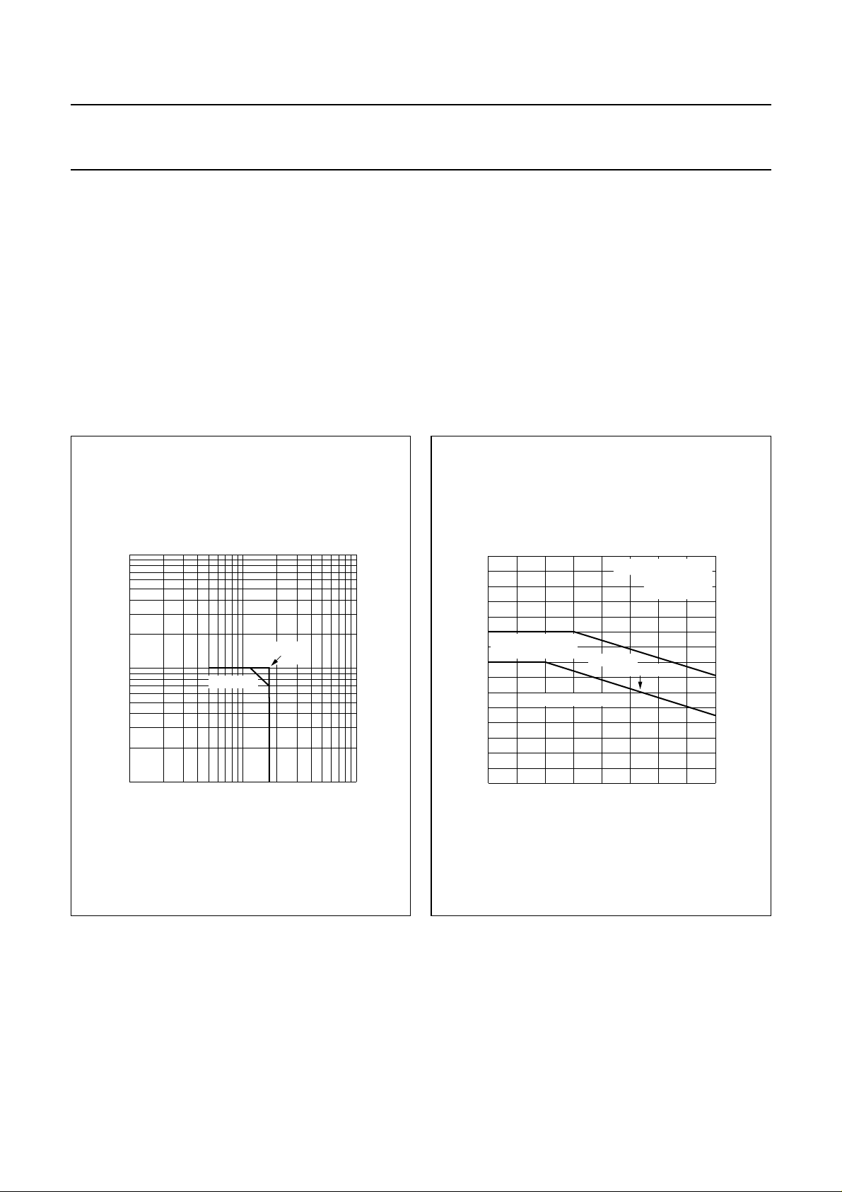
10
handbook, halfpage
I
C
(A)
1
−1
10
11010
Th = 70 °C
Fig.2 D.C. soar.
THERMAL RESISTANCE
MGP938
T
= 25 °C
mb
VCE (V)
2
30
handbook, halfpage
P
rf
(W)
20
short time operation
during mismatch
10
0
0 50 100
r.f. power dissipation
derate by
0.092 W/K
continuous operation
Th (°C)
MGP939
VCE ≤ 16.5 V
f > 1 MHz
Fig.3 R.F. power dissipation.
From junction to mounting base R
From mounting base to heatsink R
March 1993 3
th j-mb
th mb-h
= 10,3 K/W
= 0,6 K/W

Philips Semiconductors Product specification
UHF power transistor BLW80
CHARACTERISTICS
T
=25°C
j
Breakdown voltages
Collector-emitter voltage
=0;IC=10mA V
V
BE
Collector-emitter voltage
open base; I
=50mA V
C
Emitter-base voltage
open collector; IE= 4 mA V
Collector cut-off current
= 0; VCE=17V I
V
BE
D.C. current gain
(1)
IC= 0,5 A; VCE=5V h
Collector-emitter saturation voltage
(1)
IC= 1,5 A; IB= 0,3 A V
Transition frequency at f = 500 MHz
(1)
IC= 0,5 A; VCE= 12,5 V f
I
= 1,5 A; VCE= 12,5 V f
C
Collector capacitance at f = 1 MHz
IE=Ie= 0; VCB= 12,5 V C
Feedback capacitance at f = 1 MHz
IC= 40 mA; VCE= 12,5 V C
Collector-stud capacitance
(BR)CES
(BR)CEO
(BR)EBO
CES
FE
CEsat
T
T
c
re
C
cs
> 36 V
> 17 V
> 4V
< 4mA
> 10
typ 35
typ 0,75 V
typ 1,75 GHz
typ 1,25 GHz
typ 14 pF
typ 7,1 pF
typ 1,2 pF
Note
1. Measured under pulse conditions: t
≤ 200 µs; δ≤0,02.
p
March 1993 4
 Loading...