

Philips BLW77 Datasheet

DISCRETE SEMICONDUCTORS
DATA SH EET
BLW77
HF/VHF power transistor
Product specification
August 1986

Philips Semiconductors Product specification
HF/VHF power transistor BLW77
DESCRIPTION
N-P-N silicon planar epitaxial
transistor intended for use in class-AB
or class-B operated high power
transmitters in the h.f. and v.h.f.
mismatch conditions. Transistors are
delivered in matched h
groups.
FE
The transistor has a1⁄2" flange
envelope with a ceramic cap. All
leads are isolated from the flange.
bands. The transistor presents
excellent performance as a linear
amplifier in the h.f. band. It is
resistance stabilized and is
guaranteed to withstand severe load
QUICK REFERENCE DATA
R.F. performance up to T
MODE OF OPERATION V
s.s.b. (class-AB) 28 0,1 1,6 − 28 15 − 130
= 25 °C
h
V
CE
I
C(ZS)
A
f
MHz
P
W
L
G
p
dB
> 12 > 37,5
%
η
(1)
<−30
(P.E.P.)
c.w. (class-B) 28 − 87,5 130 typ. 7,5 typ. 75 −
Note
1. At 130 W P.E.P.
d
dB
3
PIN CONFIGURATION
PINNING - SOT121B.
PIN DESCRIPTION
handbook, halfpage
43
1 collector
2 emitter
3 base
4 emitter
21
MLA876
Fig.1 Simplified outline. SOT121B.
PRODUCT SAFETY This device incorporates beryllium oxide, the dust of which is toxic. The device is entirely
safe provided that the BeO disc is not damaged.
August 1986 2
Philips Semiconductors Product specification
HF/VHF power transistor BLW77
RATINGS
Limiting values in accordance with the Absolute Maximum System (IEC 134)
Collector-emitter voltage (V
peak value V
Collector-emitter voltage (open base) V
Emitter-base voltage (open collector) V
Collector current (average) I
Collector current (peak value); f > 1 MHz I
R.F. power dissipation (f > 1 MHz;); T
Storage temperature T
Operating junction temperature T
BE
= 0)
CESM
CEO
EBO
C(AV)
CM
= 25 °CP
mb
rf
stg
j
max. 70 V
max. 35 V
max. 4 V
max. 12 A
max. 30 A
max. 245 W
−65 to + 150 °C
max. 200 °C
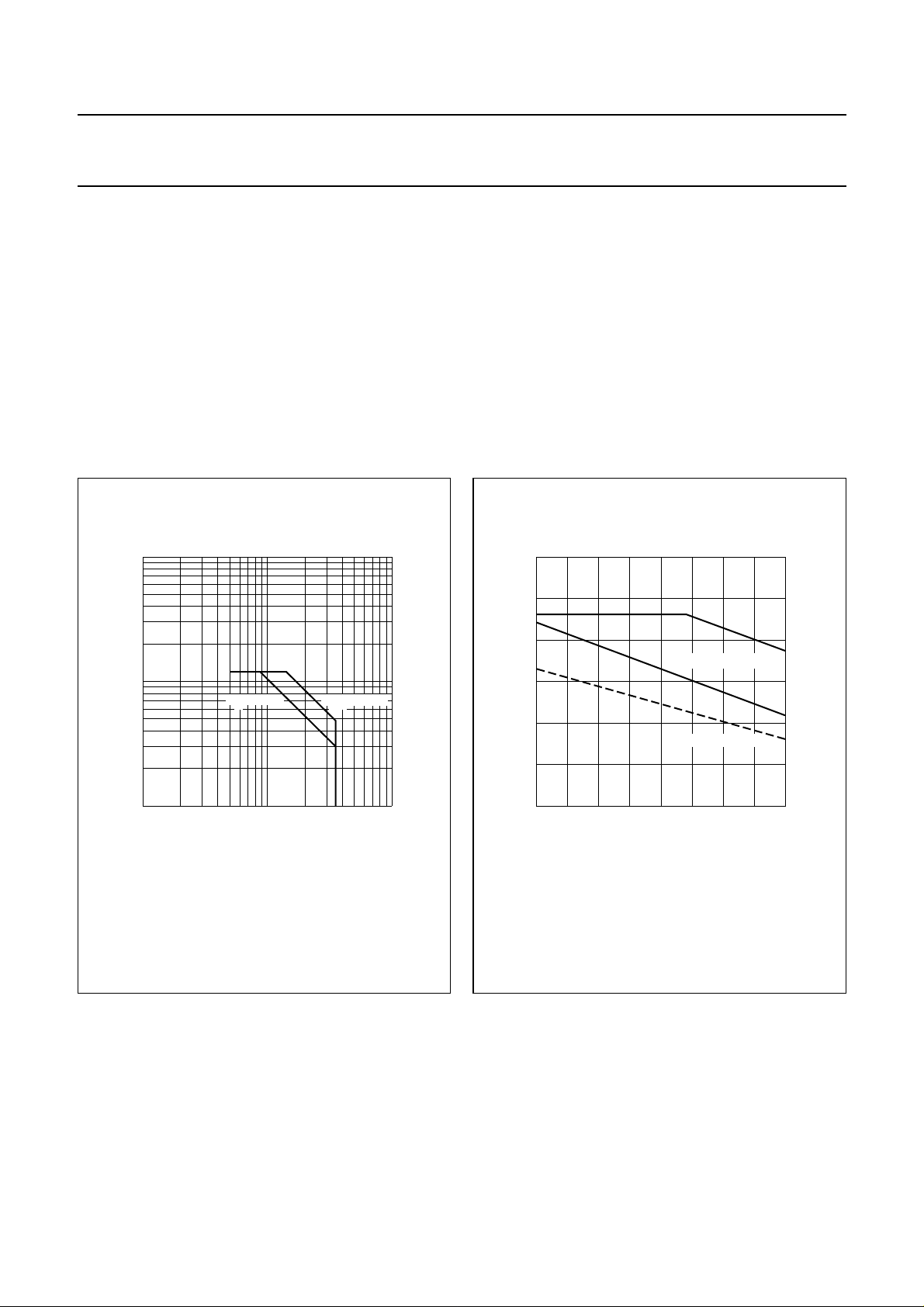
2
10
handbook, halfpage
I
C
(A)
10
1
11010
Th = 70 °C
Fig.2 D.C. SOAR.
Tmb = 25 °C
VCE (V)
MGP521
2
300
handbook, halfpage
P
rf
(W)
200
100
0
0
I Continuous d.c. operation
II Continuous r.f. operation
III Short-time operation during mismatch
ΙΙΙ
ΙΙ
Ι
derate by 1.11 W/K
derate by 0.82 W/K
50 100
Th (°C)
MGP522
Fig.3 R.F. power dissipation; VCE≤ 28 V; f ≥ 1 MHz.
THERMAL RESISTANCE
(dissipation = 100 W; T
=90°C, i.e. Th=70°C)
mb
From junction to mounting base (d.c. dissipation) R
From junction to mounting base (r.f. dissipation) R
From mounting base to heatsink R
August 1986 3
th j-mb(dc)
th j-mb(rf)
th mb-h
= 1,03 K/W
= 0,71 K/W
= 0,2 K/W
Philips Semiconductors Product specification
HF/VHF power transistor BLW77
CHARACTERISTICS
T
=25°C unless otherwise specified
j
Collector-emitter breakdown voltage
V
= 0; IC= 50 mA V
BE
Collector-emitter breakdown voltage
open base; IC= 100 mA V
Emitter-base breakdown voltage
open collector; IE= 20 mA V
Collector cut-off current
VBE= 0; VCE= 35 V I
D.C. current gain
(1)
IC= 7 A; VCE=5 V h
D.C. current gain ratio of matched devices
(1)
IC= 7 A; VCE=5 V h
Collector-emitter saturation voltage
(1)
IC= 20 A; IB=4 A V
Transition frequency at f = 100 MHz
(2)
−IE= 7 A; VCB= 28 V f
−I
= 20 A; VCB= 28 V f
E
Collector capacitance at f = 1 MHz
I
= 0; VCB= 28 V C
E=Ie
Feedback capacitance at f = 1 MHz
IC= 100 mA; VCE= 28 V C
Collector-flange capacitance C
(BR) CES
(BR) CEO
(BR)EBO
CES
FE
FE1/hFE2
CEsat
T
T
c
re
cf
> 70 V
> 35 V
> 4V
< 20 mA
15 to 80
< 1,2
typ. 2 V
typ. 320 MHz
typ. 300 MHz
typ. 255 pF
typ. 175 pF
typ. 3 pF
Notes
1. Measured under pulse conditions: t
≤ 300 µs; δ≤0,02.
p
2. Measured under pulse conditions: tp≤ 50 µs; δ≤0,01.
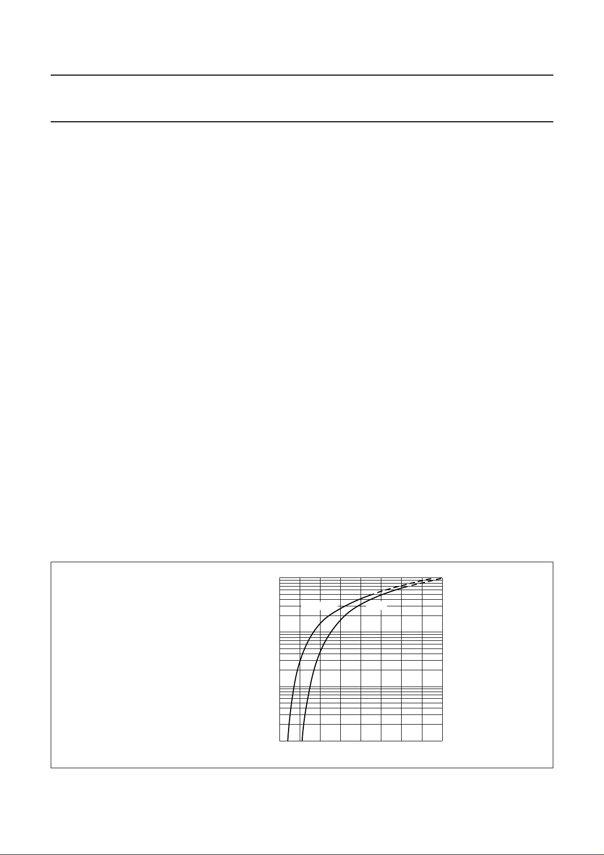
10
handbook, halfpage
I
C
(A)
1
−1
10
−2
10
Fig.4 Typical values; VCE= 20 V.
August 1986 4
Th = 70 °C
25 °C
VBE (V)
MGP523
1.50.5 1
Philips Semiconductors Product specification
HF/VHF power transistor BLW77
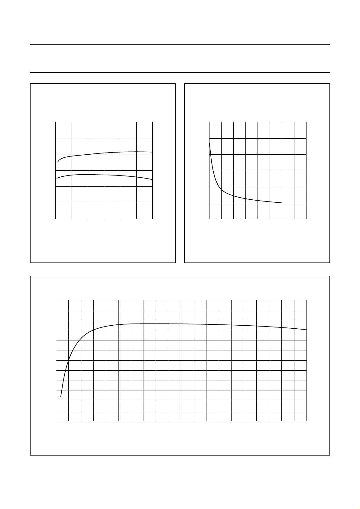
75
handbook, halfpage
h
FE
50
25
0
0 10 20 30
VCE = 28 V
5 V
IC (A)
Fig.5 Typical values; Tj=25°C.
MGP524
1500
handbook, halfpage
C
c
(pF)
1000
500
0
0
Fig.6 IE=Ie= 0; f = 1 MHz; Tj= 25 °C.
typ
20 40
VCB (V)
MGP525
400
handbook, full pagewidth
f
T
(MHz)
200
0
05 15
Fig.7 VCB= 28 V; f = 100 MHz; Tj=25°C.
August 1986 5
MGP526
typ
10
−IE (A)
20

Philips Semiconductors Product specification
HF/VHF power transistor BLW77
APPLICATION INFORMATION
R.F. performance in s.s.b. class-AB operation (linear power amplifier)
V
= 28 V; Th= 25 °C; f1= 28,000 MHz; f2= 28,001 MHz
CE
OUTPUT POWER G
15 to 130 (P.E.P.) > 12 > 37,5 < 6,2 <−30 <−30 0,1
handbook, full pagewidth
50 Ω
p
ηdt(%) IC(A) d
3
d
5
I
C(ZS)
W dB at 130 W P.E.P. dB dB A
C1
C13
C2
C3
BD443
L1
R3
C5
R1 R4
R6
C7
BD228
C6
L5
T.U.T.
C8
+V
CC
L3
C9
C10
L4
C11
R7
L2
C14
C12
50 Ω
C15
C4 R2 R5
MGP527
Fig.8 Test circuit; s.s.b. class-AB.
August 1986 6
 Loading...