

Philips BLW34 Datasheet

DISCRETE SEMICONDUCTORS
DATA SH EET
BLW34
UHF linear power transistor
Product specification
August 1986

Philips Semiconductors Product specification
UHF linear power transistor BLW34
DESCRIPTION
N-P-N silicon planar epitaxial
transistor primarily intended for use in
linear u.h.f. amplifiers for television
transmitters and transposers. The
excellent d.c. dissipation
properties for class-A operation are
area. The combination of optimum
thermal design and the application of
gold sandwich metallization
realizes excellent reliability
properties.
1
The transistor has a
⁄4" capstan
envelope with ceramic cap.
obtained by means of diffused emitter
ballasting resistors and a multi-base
structure, providing an optimum
temperature profile on the crystal
QUICK REFERENCE DATA
R.F. performance
MODE OF OPERATION f
vision
MHz
V
CE
V
I
C
mA
T
°C
h
(1)
d
im
P
dB
o sync
W
(1)
G
dB
p
class-A; linear amplifier 860 25 600 70 −60 > 1,8 > 9
860 25 600 25 −60 typ. 2,15 typ. 10,2
Note
1. Three-tone test method (vision carrier −8 dB, sound carrier −7 dB, sideband signal−16 dB), zero dB corresponds to
peak sync level.
PIN CONFIGURATION
PINNING - SOT122A.
PIN DESCRIPTION
1 collector
2 emitter
Top view
4
31
2
MBK187
3 base
4 emitter
handbook, halfpage
Fig.1 Simplified outline. SOT122A.
PRODUCT SAFETY This device incorporates beryllium oxide, the dust of which is toxic. The device is entirely
safe provided that the BeO disc is not damaged.
August 1986 2
Philips Semiconductors Product specification
UHF linear power transistor BLW34
RATINGS
Limiting values in accordance with the Absolute Maximum System (IEC 134)
Collector-emitter voltage
(peak value); V
open base V
Emitter-base voltage (open collector) V
Collector current
d.c. or average I
(peak value); f > 1 MHz I
Total power dissipation at T
Storage temperature T
Operating junction temperature T
=0 V
BE
=25°CP
mb
CESM
CEO
EBO
C
CM
tot
stg
j
max. 50 V
max. 30 V
max. 4 V
max. 2,25 A
max. 3,5 A
max. 31 W
−65 to +150 °C
max. 200 °C
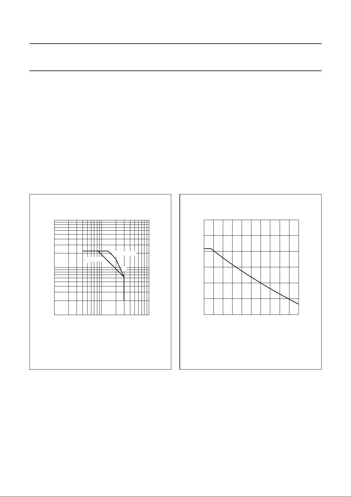
10
handbook, halfpage
I
C
(A)
Tmb = 25 °C
Th = 70 °C
1
−1
10
1 10 10
(1) Second breakdown limit (independent of temperature).
(1)
VCE (V)
Fig.2 D.C. SOAR.
THERMAL RESISTANCE (see Fig.4)
MGP454
40
handbook, halfpage
P
tot
(W)
30
20
2
10
0
50
Th (°C)
MGP455
100
Fig.3 Power derating curve vs. temperature.
From junction to mounting base
(dissipation = 15 W; Tmb=79°C; i.e. Th=70°C) R
From mounting base to heatsink R
August 1986 3
th j-mb
th mb-h
= 6,2 K/W
= 0,6 K/W
Philips Semiconductors Product specification
UHF linear power transistor BLW34
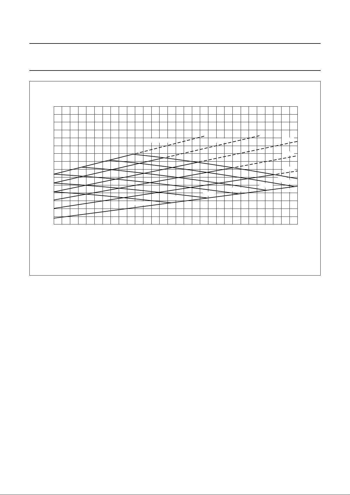
10
handbook, full pagewidth
R
th j-h
(K/W)
8
6
4
0
75 °C
Th = 125 °C
100 °C
125 °C
100 °C
2010
150 °C
175 °C
P
(W)
tot
MGP456
75 °C
50 °C
25 °C
T
=
j
200
0 °C
Fig.4 Maximum thermal resistance from junction to heatsink as a function of power dissipation, with heatsink
and junction temperature as parameters. (R
th mb-h
= 0,6 K/W.)
°C
30
Example
Nominal class-A operation: V
Fig.4 shows: R
Typical device: R
T
T
th j-h
j
th j-h
j
= 25 V; IC= 600 mA; Th=70°C.
CE
max. 6,75 K/W
max. 170 °C
typ. 5,45 K/W
typ. 152 °C
August 1986 4
 Loading...