

Philips BLU99-SL, BLU99 Datasheet
DISCRETE SEMICONDUCTORS
DATA SH EET
BLU99
BLU99/SL
UHF power transistor
Product specification
March 1993
Philips Semiconductors Product specification
UHF power transistor
DESCRIPTION
N-P-N silicon planar epitaxial
transistor primarily intended for use in
mobile radio transmitters in the u.h.f.
band. The transistor is also very
suitable for application in the
900 MHz mobile radio band.
QUICK REFERENCE DATA
R.F. performance at T
MODE OF OPERATION
narrow band; c.w.
=25°C in a common-emitter class-B circuit.
h
BLU99
BLU99/SL
FEATURES
• multi-base structure and diffused
emitter-ballasting resistors for an
optimum temperature profile;
• gold metallization ensures
excellent reliability.
The BLU99 has a 4-lead stud
envelope with a ceramic cap
(SOT122A). All leads are isolated
from the stud. The BLU99/SL is a
studless version (SOT122D).
V
CE
V
12,5 470 5 > 10,5 > 60
12,5 900 4 typ. 7,0 typ. 60
f
MHz
P
W
L
G
p
dB
η
C
%
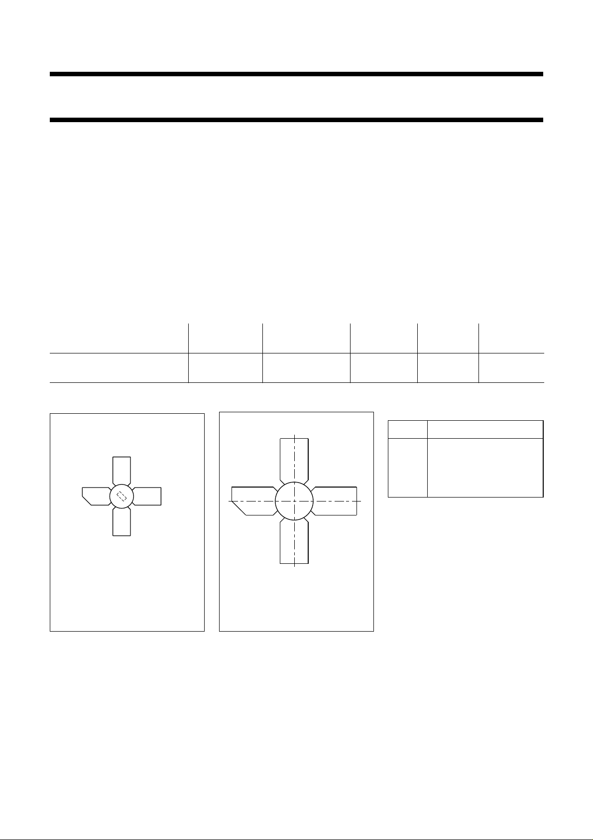
PIN CONFIGURATION
PINNING - SOT122A; SOT122D
PIN DESCRIPTION
page
ge
4
31
4
1 collector
2 emitter
31
3 base
4 emitter
2
Top view
Fig.1 Simplified outline.
SOT122A
(BLU99).
MBK187
2
MSB055
Fig.2 Simplified outline.
SOT122D
(BLU99/SL).
PRODUCT SAFETY This device incorporates beryllium oxide, the dust of which is toxic. The device is entirely
safe provided that the BeO disc is not damaged.
March 1993 2
Philips Semiconductors Product specification
UHF power transistor
RATINGS
Limiting values in accordance with the Absolute Maximum System (IEC 134)
Collector-base voltage (open emitter) V
Collector-emitter voltage (open base) V
Emitter-base voltage (open collector) V
Collector current
d.c. or average I
peak value; f > 1 MHz I
D.C. power dissipation up to T
=50°CP
mb
R.F. power dissipation
f > 1 MHz; T
=25°CP
mb
Storage temperature T
Operating junction temperature T
MDA372
I
(A)
1
C
handbook, halfpage
Tmb = 50 °C
Th = 70 °C
CBO
CEO
EBO
C;IC(AV)
CM
tot (d.c.)
tot (r.f.)
stg
j
28
handbook, halfpage
P
tot
(W)
20
BLU99
BLU99/SL
max. 36 V
max. 16 V
max. 3 V
max. 0,8 A
max. 2,5 A
max. 12,5 W
max. 19 W
−65 to + 150 °C
max. 200 °C
MDA373
III
12
−1
R
10
th mb-h
1
= 0,6 K/W.
10 10
VCE (V)
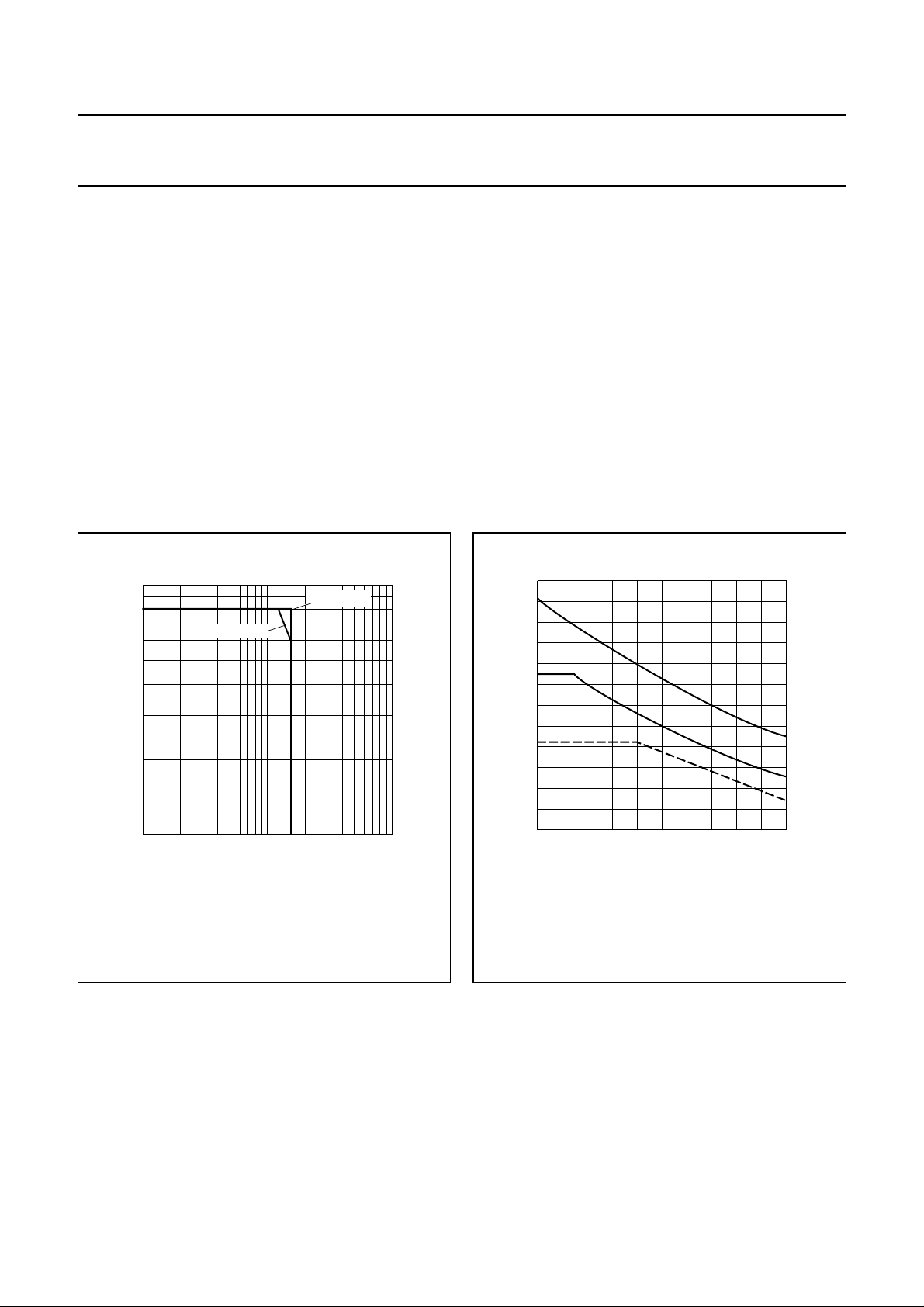
2
I Continuous d.c. operation
II Continuous r.f. operation (f > 1 MHz).
III Short-time r.f. operation during mismatch (f > 1 MHz).
Fig.3 D.C. SOAR.
THERMAL RESISTANCE
(dissipation = 9 W; T
=25°C)
mb
From junction to mounting base
(d.c. dissipation) R
From junction to mounting base
(r.f. dissipation) R
From mounting base to heatsink R
II
I
4
0
20
40 60 80
Th (°C)
100
Fig.4 Power/temperature derating curves.
th j-mb(dc)
th j-mb(rf)
th mb-h
= 10 K/W
= 7,5 K/W
= 0,6 K/W
March 1993 3

Philips Semiconductors Product specification
UHF power transistor
CHARACTERISTICS
T
=25°C unless otherwise specified
j
Collector-base breakdown voltage
open emitter; I
Collector-emitter breakdown voltage
open base; IC= 20 mA V
Emitter-base breakdown voltage
open collector; IE= 1 mA V
Collector cut-off current
VBE= 0; VCE= 16 V I
Second breakdown energy; L = 25 mH; f = 50 Hz
R
=10Ω E
BE
D.C. current gain
IC= 0,6 A; VCE= 10 V h
Transition frequency at f = 500 MHz
IC= 0,6 A; VCE= 12,5 V f
Collector capacitance at f = 1 MHz
I
= 0; VCB= 12,5 V C
E=Ie
Feedback capacitance at f = 1 MHz
I
= 0; VCE= 12,5 V C
C
Collector-stud capacitance C
= 10 mA V
C
(2)
(1)
(BR)CBO
(BR)CEO
(BR)EBO
CES
SBR
FE
T
c
re
cs
BLU99
BLU99/SL
> 36 V
> 16 V
> 3V
< 5mA
> 1mJ
>
typ.25100
typ. 4,0 GHz
typ. 7,5 pF
typ. 5 pF
typ. 1,2 pF
Notes
1. Measured under pulse conditions: t
=50µs; δ<0,01.
p
2. Measured under pulse conditions: tp= 300 µs; δ<0,01.
March 1993 4
Philips Semiconductors Product specification
UHF power transistor
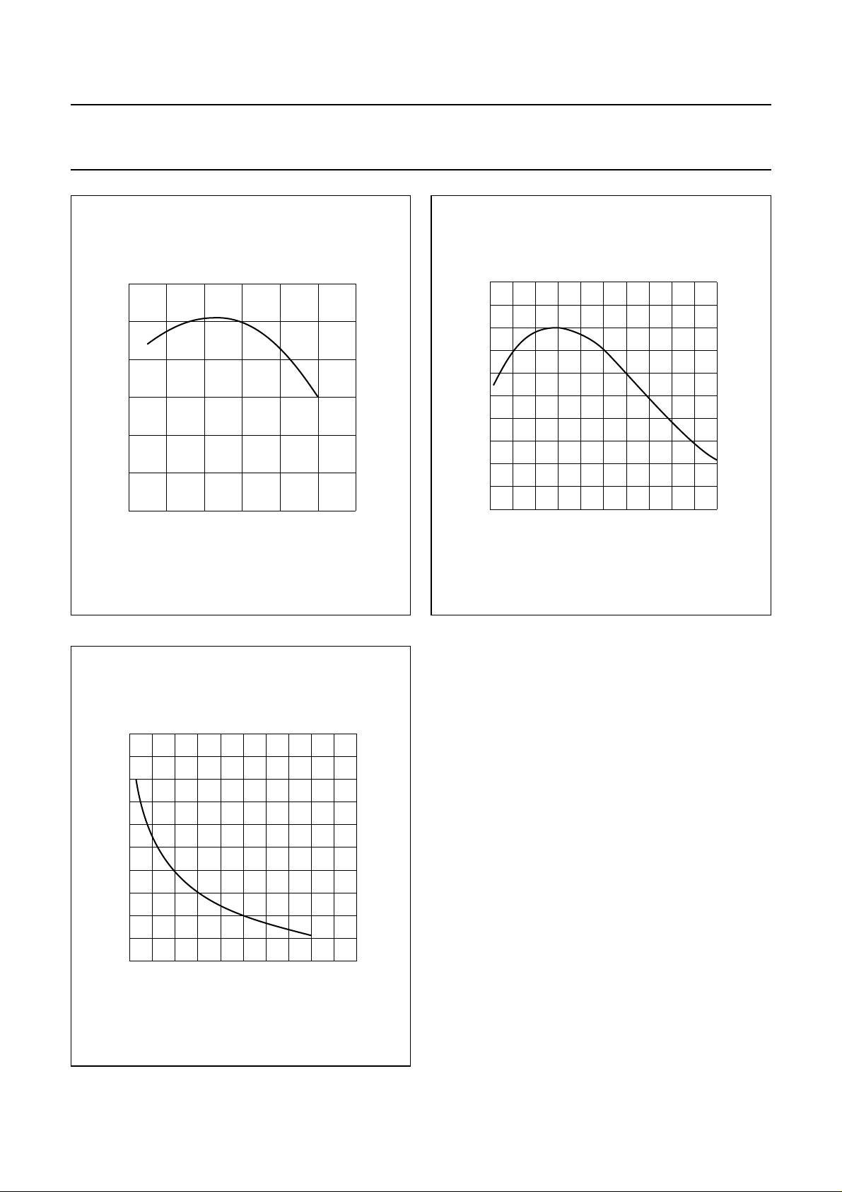
120
handbook, halfpage
h
FE
80
40
0
0
0.8
MDA374
1.6 2.4
IC (A)
handbook, halfpage
5
f
T
(GHz)
4
3
2
1
0
02
0.4 0.8 1.2
BLU99
BLU99/SL
MDA375
1.6
IE (A)
Fig.5 VCE= 10 V; Tj=25°C; typ. values.
16
handbook, halfpage
C
c
(pF)
14
12
10
8
6
020
4812
16
VCB (V)
Fig.6 VCB= 12,5 V; f = 500 MHz; Tj=25°C;
typ. values.
MDA376
Fig.7 IE=ie= 0; f = 1 MHz; typ. values.
March 1993 5
Philips Semiconductors Product specification
UHF power transistor
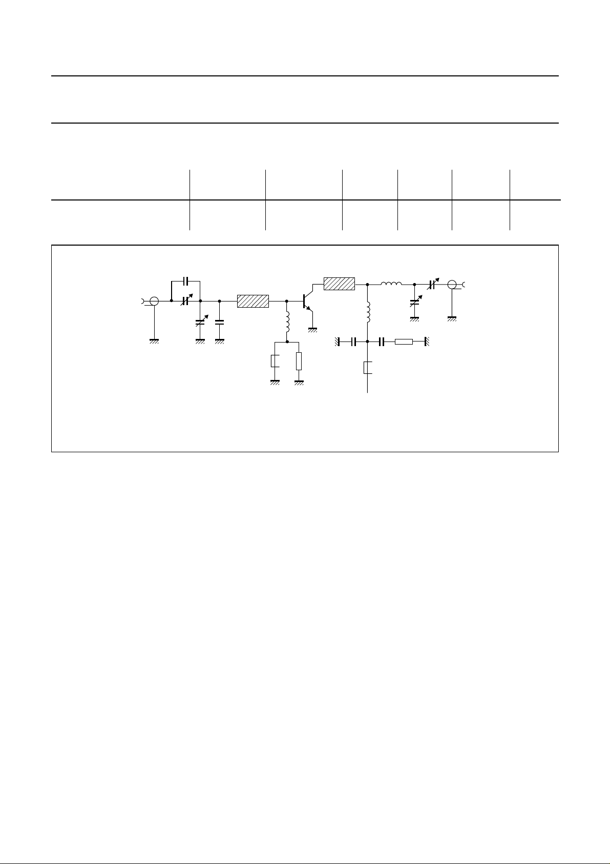
APPLICATION INFORMATION (part I) R.F. performance in c.w. operation (common-emitter class-B circuit) at f = 470 MHz; T
V
MODE OF OPERATION
CE
V
narrow band; c.w. 12,5 5
handbook, full pagewidth
50 Ω
C1
C2
C4
L1
C3
L3 R1
P
L
W
P
S
W
< 0,45 > 10,5 < 0,665 > 60
typ. 0,32 typ. 12 typ. 0,60 typ. 66
T.U.T.
L6
L2
C5 C6
L4
+V
L7
L5
R2
CC
h
G
dB
MDA365
=25°C.
p
C8
C7
BLU99
BLU99/SL
I
C
A
50 Ω
η
C
%
Fig.8 Class-B test circuit at f = 470 MHz.
List of components:
C1 = 2,7 pF multilayer ceramic chip capacitor
(1)
C2 = C7 = C8 = 1,4-5,5 pF film dielectric trimmer (cat.no. 2222 809 09001)
C3 = 7,5 pF multilayer ceramic chip capacitor
(1)
C4 = 2-9 pF film dielectric trimmer (cat.no. 2222 809 09002)
C5 = 100 pF multilayer ceramic chip capacitor (cat. no. 2222 852 13101)
C6 = 100 nF metallized film capacitor (cat. no. 2222 352 45104)
L1 = stripline, 22,5 mm × 6,0 mm
L2 = 1 turn Cu-wire (1,0 mm), int. dia. 5,5 mm, leads 2 × 5 mm
L3 = L4 = Ferroxcube wideband h.f. choke, grade 3B (cat. no. 4312 020 36642)
L5 = 4 turns enamelled Cu-wire (1,0 mm), int. dia. 6 mm, length 7,5 mm, leads 2 × 5 mm
L6 = stripline, 10,0 mm × 6,0 mm
L7 = 1 turn Cu-wire (1,0 mm), int. dia. 5 mm, leads 2 × 5 mm
R1 = R2 = 10 Ω metal film resistor, 0,25 W
L1 and L6 are striplines on a double Cu-clad printed circuit board with P.T.F.E. fibre-glass dielectric (εr= 2,74) and a
thickness of1⁄16 inch.
Note
1. American Technical Ceramics capacitor type 100 A or capacitor of same quality.
March 1993 6
 Loading...