

Philips BGR69 Datasheet
DISCRETE SEMICONDUCTORS
DATA SH EET
ook, halfpage
M3D252
BGR69
Hybrid CATV amplifier module
Objective specification 2000 Apr 26
Philips Semiconductors Objective specification
Hybrid CATV amplifier module BGR69
FEATURES
• Extremely low noise
• Excellent linearity
• Silicon nitride passivation
• Rugged construction
• Gold metallization ensures excellent reliability.
APPLICATIONS
• Reverse amplifier in two-way CATV systems operating
in the frequency range of 5 to 65 MHz.
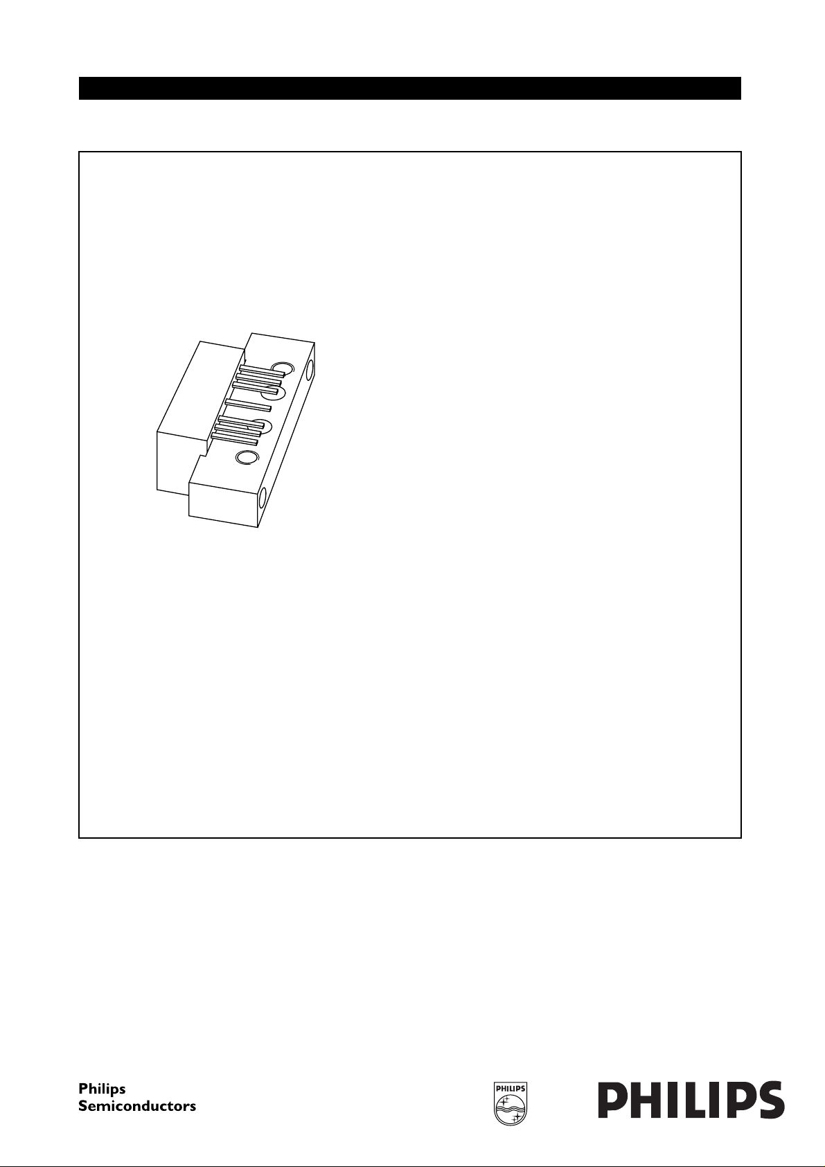
DESCRIPTION
The BGR69is a high performance amplifier operating at a
voltage supply of 24 V in a SOT115J package.
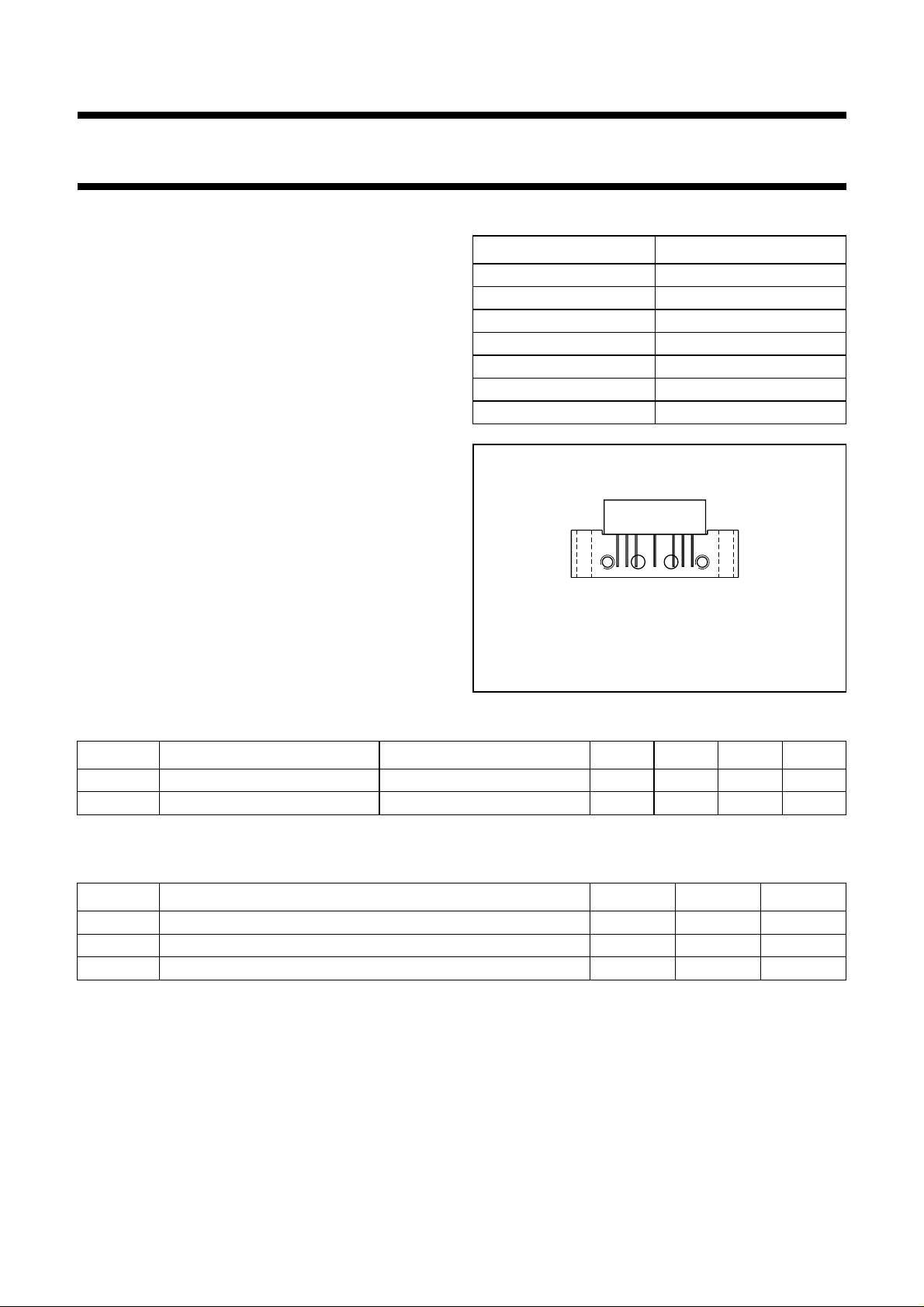
PINNING SOT115J
PIN DESCRIPTION
1 input
2 common
3 common
5+V
7 common
8 common
9 output
handbook, halfpage
Side view
Fig.1 Simplified outline.
B
2
789
351
MSA319
QUICK REFERENCE DATA
SYMBOL PARAMETER CONDITIONS MIN. TYP. MAX. UNIT
G
p
I
tot
power gain f = 5 MHz 34.5 35 35.5 dB
total current consumption DC value; VB=24V −−220 mA
LIMITING VALUES
In accordance with the Absolute Maximum Rating System (IEC 60134).
SYMBOL PARAMETER MIN. MAX. UNIT
V
i
T
mb
T
stg
RF input voltage − 65 dBmV
operating mounting base temperature −20 +100 °C
storage temperature −40 +100 °C
2000 Apr 26 2
Philips Semiconductors Objective specification
Hybrid CATV amplifier module BGR69
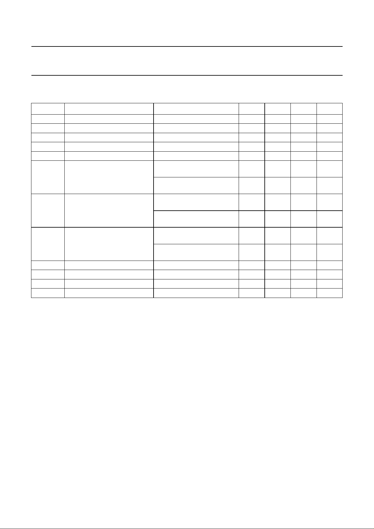
CHARACTERISTICS
Bandwidth 5 to 65 MHz; VB=24V; Tmb=30°C; ZS=ZL=75Ω.
SYMBOL PARAMETER CONDITIONS MIN. TYP. MAX. UNIT
G
p
SL slope straight line f = 5 to 65 MHz 0 − 0.5 dB
FL flatness of frequency response f = 5 to 65 MHz −−±0.2 dB
s
11
s
22
CTB composite triple beat 6 chs flat; V
X
mod
CSO composite second order
d
2
d
3
F noise figure f = 65 MHz −−4dB
I
tot
power gain f = 5 MHz 34.5 35 35.5 dB
input return losses f = 5 to 65 MHz 20 −−dB
output return losses f = 5 to 65 MHz 20 −−dB
= 50 dBmV;
o
−−−73 dB
measured at 37.25 MHz
10 chs flat; V
= 50 dBmV;
o
−−−57 dB
measured at 61.25 MHz
cross modulation 6 chs flat; Vo= 50 dBmV;
−−−66 dB
measured at 37.25 MHz
10 chs flat; V
= 50 dBmV;
o
−−−57 dB
measured at 61.25 MHz
distortion
6 chs flat; V
measured at 24 or 38.5 MHz
10 chs flat; V
= 50 dBmV;
o
= 50 dBmV;
o
−−−68 dB
−−−65 dB
measured at 24 or 62.5 MHz
second order distortion note 1 −−−70 dB
third order distortion note 2 −−−80 dB
total current consumption note 3 −−220 mA
Notes
1. f
= 25.25 MHz; Vp= 50 dBmV; fq= 37.25 MHz; Vq= 50 dBmV; measured at f
p
= 62.5 MHz.
(p+q)
2. fp= 7.25 MHz; Vp= 50 dBmV; fq= 19.25 MHz; Vq= 50 dBmV; fr= 37.25 MHz; Vr= 50 dBmV; measured at
fp+fq+fr= 63.75 MHz.
3. The module normally operates at VB= 24 V, but is able to withstand supply transients up to 30 V.
2000 Apr 26 3
 Loading...