

Page 1
Colour Monitor Commercial Type Number
BDS4241V/00
BDH4241V/00
BDH5021V/00
G_16680_000.eps
150906
Contents Page
1 Specification 5
2 Engineering Specification 8
3 Block Diagram 32
4 Circuit 33
5 Exploded View 47
6 Calibration Methods 58
7 Inspection Methods 63
8 Firmware Upgrade Method 95
9 Serial Control Protocols 97
10 Trouble Shooting 101
11 PDP Module Service Manual 109
12 Spare Parts List 186
©
Copyright 2006 Philips Consumer Electronics B.V. Eindhoven, The Netherlands.
All rights reserved. No part of this publication may be reproduced, stored in a
retrieval system or transmitted, in any form or by any means, electronic,
mechanical, photocopying, or otherwise without the prior permission of Philips.
Published by MW 0669 BG CD Customer Service Printed in the Netherlands Subject to modification EN 3122 785 16680
Note:
Repair of these products may only be performed by BDS authorised
workshops.
Page 2

2/185
DISCLAIMER
WoosungNextier Corp. shall not be liable for technical or omissions contained
herein: nor for
incidental or consequential damages resulting from the furnishing, performance,
or use of this material.
WoosungNextier Corp. reserves the right to change any or all specifications
without notice.
Information in this document may change without notice.
CONFIDENTIALITY
All material contained within this document is proprietary information and the
sole
property of WoosungNextier Corp. #821~3, Byucksan Digital ValleyⅡ, 481-10,
gasan-dong, Geumcheon-Gu, Seoul-city, Korea.
No part of this document may be copied, reproduced, or transmitted by any
means, for any purpose without prior written permission from WoosungNextier
Corp.
Page 3
3/185
Service Manual Revision
Date Description By Approved
2006.06.16 1st edit (for philips, EU)
2006.08.08 Exploded view modify (for philips, EU)
2006.09. 15 Spare Parts BOM added incl. 12ncs
Page 4

4/185
C O N T E N T S
◆ SPECIFICATION----------------------------------------5
◆ ENGINEERING SPECIFICATION------------------8
◆ BLOCK DIAGRAM-------------------------------------32
◆ CIRCUIT --------------------------------------------------33
◆ BOM
-------------------------See Separate Document
◆ EXPLODED VIEW--------------------------------------47
◆ CALIBRATION METH
◆ INSPECTION METH
◆ FIRMWARE UPGRADE
ODS--------------------------58
ODS-----------------------------63
METHOD-----------------95
◆ SERIAL CONTROL PROTOCOLS------------------97
◆ TROUBLE SHOOTING-------------------------------
101
◆ PDP MODULE SERVICE MANUAL---------------
109
Page 5

Specifications for PDP Monitor (Plilps Europe)
5/185
Model : BDS4241V/00, BDH4241V/00, BDH5021V/00
Main Features
● Pixelworks DNX™ (Digital Natural Expression) technology including
Pixelworks DNX™ (Digital Natural Expression) technology
dramatically enhances the quality of video images
by combining multiple Pixelworks video processing technologies
to deliver clear,natural-looking standard and high-definition video images.
DNX technology
advanced scaling,motion-adaptive deinterlacing,noise reduction,
dynamic edge enhancement,and smoothing of moving lines to deliver a lifelike picture.
● High Brightness and High Contrast Ratio
● Dual HDMI Input (Option)
● Built in Speakers (Option)
● HDMI(High Definition Multimedia Interface) Support Up to 720p,1080i,1280x1024/60 Hz(SXGA)
● DVI(Digital Visual Interface) Support Up to 720p , 1080i , 1280 x 1024 / 60 Hz (SXGA)
● HDCP(High-bandwidth Digital Content Protection) Supported
● Multi-Standard RGB(PC) Monitor Support Up to 720p , 1080i , 1280 x 1024 / 60 Hz (SXGA)
● Multi-Standard Component Signal Compatibility : 480i , 576i , 480p , 576p , 720p , 1080i
● Multi-Standard Video System Supported : NTSC , PAL , SECAM
● Multi-screen display : Normal , PiP/PBP(Option)
● Variable Image size : Auto,Fill All(16:9),Fill Aspect,Zoom,Anamorphic,Wide
● Variable Picture control : Brightness , Contrast , Sharpness , Color , Tint
● Variable Audio control : Volume , Mute , Bass , Treble , Balance
● Video Enhancement features including
• DCTI(Digital Chroma Transient) / DLTI(Digital Luminance Transient Improvement)
• Digital luminance peaking and Horizontal Peaking
• Enhanced sharpness controls
• Advanced Noise Reduction including progressive sources
• Flesh Tone Correction (FTC)
• Chroma Upsampling Error (CUE) correction
• Improved White and Black-level expansion
• Digital 3D Comb-filter (Option)
• Digital brightness, contrast, hue, and saturation control
• PixelBoost™(Pixelworks) overdrive technology for video format
• Improved scaler and filters for sharper images
• Improved multi-region, anamorphic scaling for 4:3<->16:9 aspect ratio conversion
• Independent vertical and horizontal scalers
• True 10-bit(1 billion color) processing (Option)
● Deinterlacing features including
• Improved deinterlacer, supporting SDTV and HDTV, for standard NTSC/PAL/SECAM,1080i
• Per-pixel motion-compensated deinterlacing
• Improved Low-Angle Interpolation
• Film mode for 3:2/2:2 pull-down materials, including 1080i sources
● Audio Enhancement features including
• Automatic Volume Correction (AVC)
• Audio Delay for "Lip Sync" (Option)
• Spatial Effects
• Pseudo Stereo
● Multi-Language On Screen Display (OSD)
● Still image function
● Image Sticking Minimum Function
● Sleep Timer
● TeleText support one thousands of pages (1K page)
● Quiet Fanless Operation
● Ultra slim & light design
combines sophisticated digital video processing techniques,
(Option)
Page 6
(9 pin)
g
p
g
p
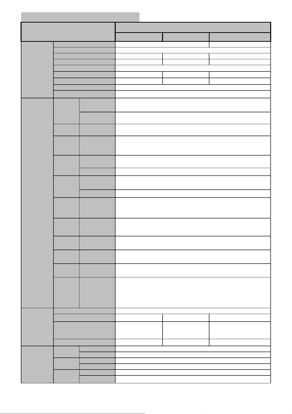
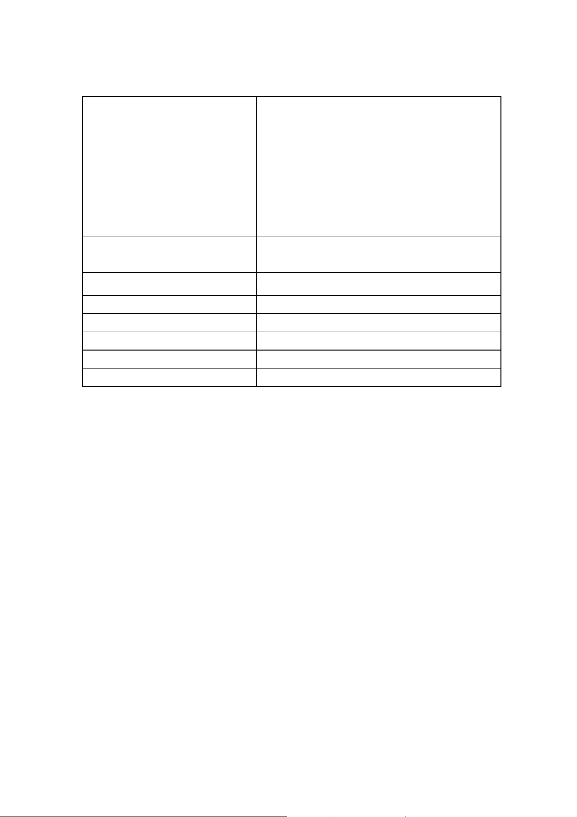
PDP Monitor
6/185
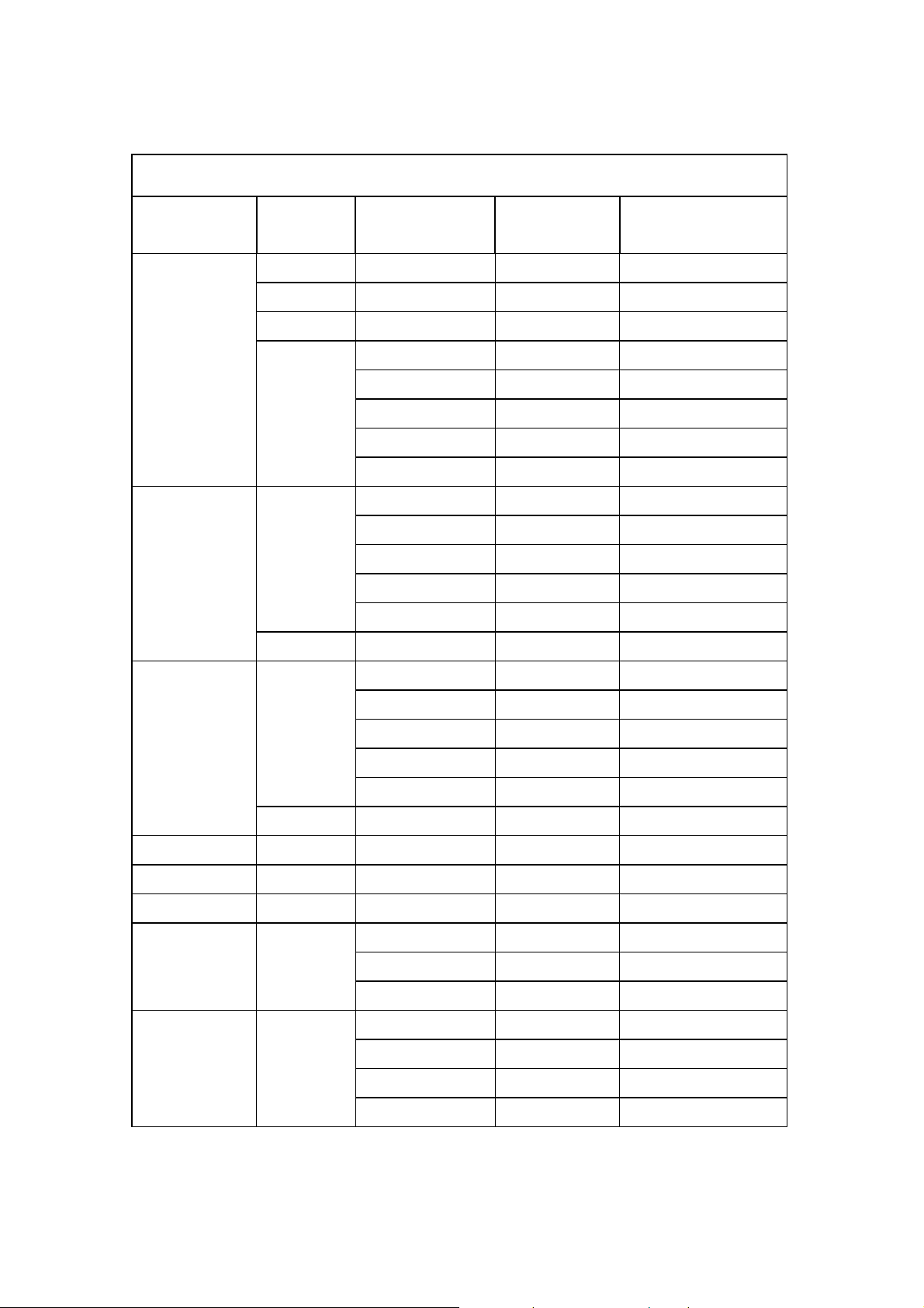
Item
BDS4241V/00 BDH4241V/00
Screen Size(Active Area)
Aspect ratio
Number of Pixels
Pixel Pitch
Display
Displayable Colors
Brightness
Contrast Ratio
Color Temperature
Viewing Angle
Internal Speaker
Speaker
Output
RS-232C
HDMI
Input
(Option)
DVI
Input
RGB
Input
(Option)
External Speaker
(Option)
D-Sub Jack x 1
HDMI Jack x 2
(Type A)
DVI Jack x 1
(24 pin)
RCA Jack x 1
D-Sub Jack x 1
(15 pin)
RCA Jack x 1
In / Out
Terminals
Component
Input
Digital Audio
Output
(Option)
Monitor
Output
S-Video
Input
Video
Input
Scart 1 , 2
RCA Jack x 1
Optical Jack x 1
RCA Jack x 1
Mini DIN Jack x1
(4 pin)
RCA Jack x 1
Scart Jack x 2
(21 pin)
[Full x 1, Half x 1]
or
RCA Jack x 2
Power Supply
Power Consumption (Typical)
General
Dimensions (Without Stand)
[ W mm x H mm x D mm ]
Weight (Without Stand)
Operational
e
Stora
erational
O
e
Stora
erational
O
Storage
Environment
Condition
Temperature
Humidity
Pressure
* The specifications are subject to change without notice
852 (H) x 480 (V)
1.080(H) x 1.080(V) [mm] 0.900(H) x 0.676(V) [mm]
1500 cd/㎡ 1200 cd/㎡
10W(L) + 10W(R) [RMS] / 8 Ω
2 Way 2 Speaker(A,B,C,D) or 2 Way 4 Speaker (E)
10W(L) + 10W(R) [RMS] / 8 Ω
2 Way 4 Speaker System
TXD + RXD (1:1)
Digital RGB : TMDS (Video + Audio)
MAX : Video - 720p , 1080i , 1280 x 1024 / 60 Hz (SXGA)
Audio - 48kHz / 2 Channel (L + R)
Digital RGB : TMDS
MAX : 720p , 1080i , 1280 x 1024 / 60 Hz (SXGA)
Audio : 0.5V[rms](Normal) / 2 Channel (L+R)
Analog RGB : 0.7V[p-p](75Ω), H/CS/V : TTL (2.2 kΩ), SOG : 1V[p-p](75Ω)
MAX : 720p , 1080i , 1280 x 1024 / 60 Hz (SXGA)
Audio : 0.5V[rms](Normal) / 2 Channel (L+R)
Y:1V[p-p](75Ω) , Pb/Cb:0.7V[p-p](75Ω) , Pr/Cr:0.7V[p-p](75Ω)
480i , 576i , 480p , 576p , 720p , 1080i
Audio : 0.5V[rms](Normal) / 2 Channel (L+R)
3V[p-p] ( 75 Ω)
48kHz Sampling ( 4 Hz ~ 22 KHz)
Video : 1V[p-p] ( 75 Ω)
Audio : 0.5V[rms](Normal) / 2 Channel (L + R)
Y: 1V[p-p] ( 75 Ω) , C: 0.286V[p-p] ( 75 Ω) [NTSC]
Y: 1V[p-p] ( 75 Ω) , C: 0.300V[p-p] ( 75 Ω) [PAL / SECAM]
Video : 1V[p-p] ( 75 Ω) [ NTSC / PAL / SECAM]
Audio : 0.5V[rms](Normal) / 2 Channel (L + R)
Video : 1V[p-p] ( 75 Ω)
Y : 1V[p-p] ( 75 Ω) , C: 0.3V[p-p] ( 75 Ω)
RGB : 0.7V[p-p] ( 75 Ω)
Audio : 0.5V[rms](Normal) / 2 Channel (L+R)
290W
1028 x 625 x 89.8 (A)
1028 x 625 x 107.4 (B)
1194 x 655 x 105.3 (E)
29 kg(A,B) / 31 kg(E)
Specifications
42" (920.1(H) x 518.4(V)±0.5mm)
1024 (H) x 768 (V)
1 billion (Option)
10000:1
20 ~ 80% RH (No condensation)
10 ~ 90% RH (NO condensation)
800 ~ 1100 hPa (Altitude : 0 ~ 2,000 m)
700 ~ 1100 hPa (Altitude : 0 ~ 3,000 m)
8000:1
Over 160 degrees
AC 100V ~ 240V, 50/60Hz
350W
1028 x 625 x 107.4 (B)
1194 x 655 x 105.3 (E)
31 kg(B) / 33 kg(E)
BDH5012V/00
50" (1106.5(H) x 622.1(V)±0.5mm)
16:9
1366 (H) x 768 (V)
0.810(H) x 0.810(V) [mm]
1000 cd/㎡
8000:1
9500 K
450W
1205 x 721 x 114.3 (C)
1205 x 721 x 114.3 (D)
43 kg
0 ~ 40 ℃
-20 ~ 60 ℃
Page 7
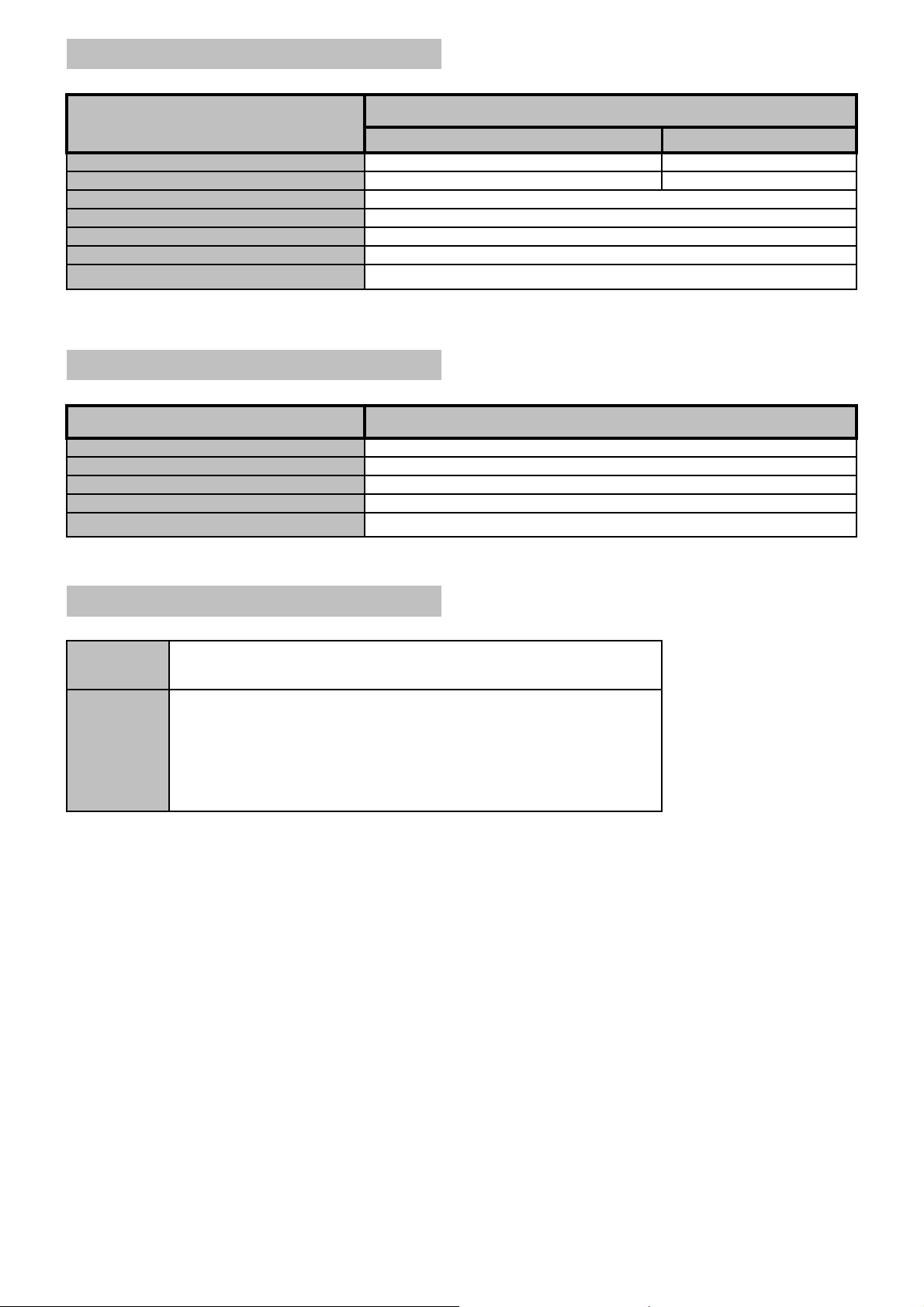
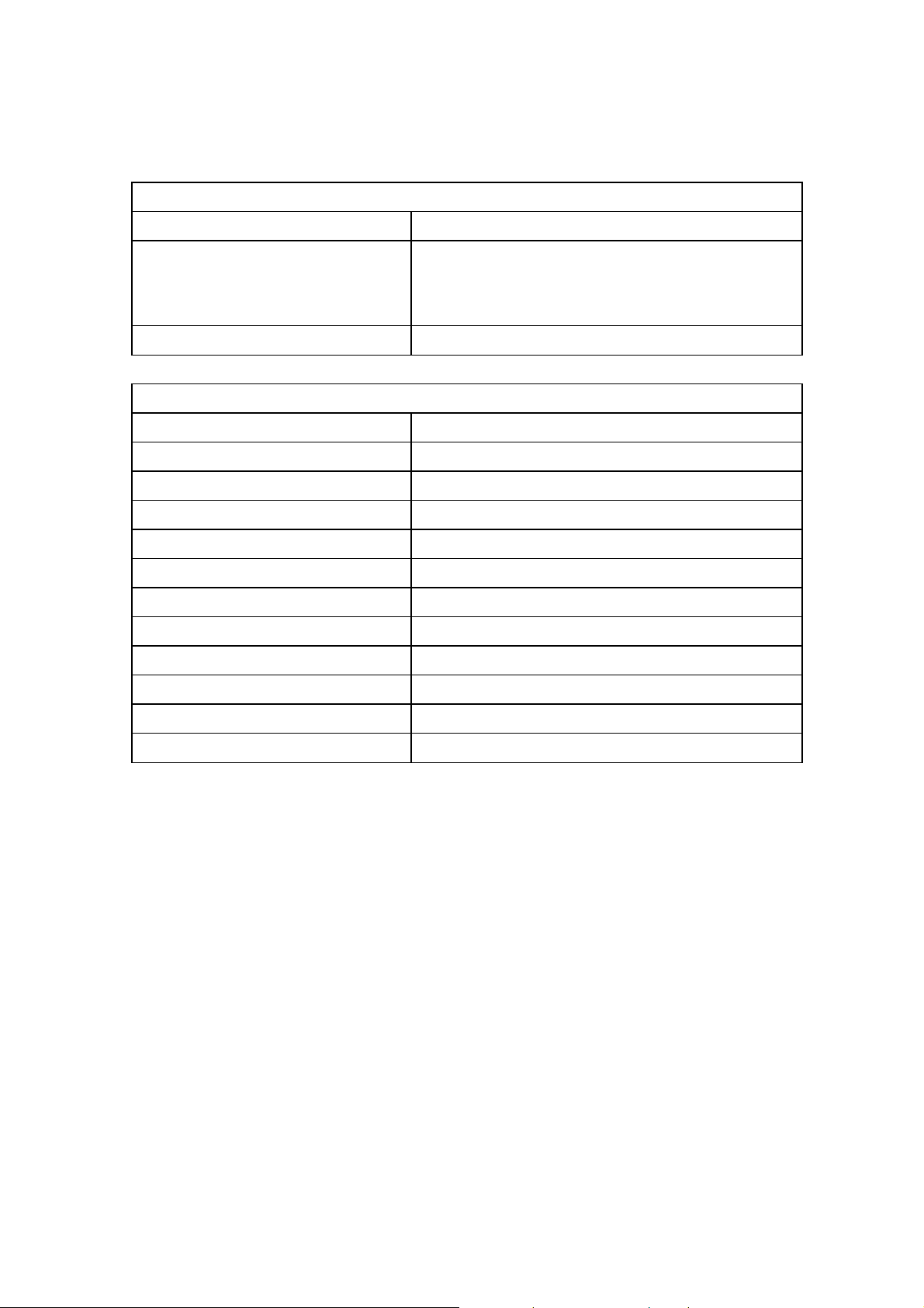
External Speaker (Option)
m
7/185
Item
BDS4241V/00, BDH4241V/00
Dimensions (W x H x D)
Weight
Type
Input
Impedence
Output Sound Pressure
Frequency Response
* The specifications are subject to change without notice
113 mm x 626.6 mm x 82.2 mm
Internal Speaker (Option)
Item
Type
Input
Impedence
Output Sound Pressure
Frequency Response
* The specifications are subject to change without notice
Specifications
BDH5021V/00
90 mm x 721 mm x 68 m
5 kg ( L + R )
2 Way 4 Speaker System
10 W ( RMS)
8 Ω
87 dB/W/M
45 Hz ~ 20 KHz
3 kg ( L + R )
Specifications
2 Way 2 Speaker(A,B,C,D) or 2 Way 4 Speaker (E)
10 W ( RMS)
8 Ω
88 dB/W/M
140 Hz ~ 10 KHz
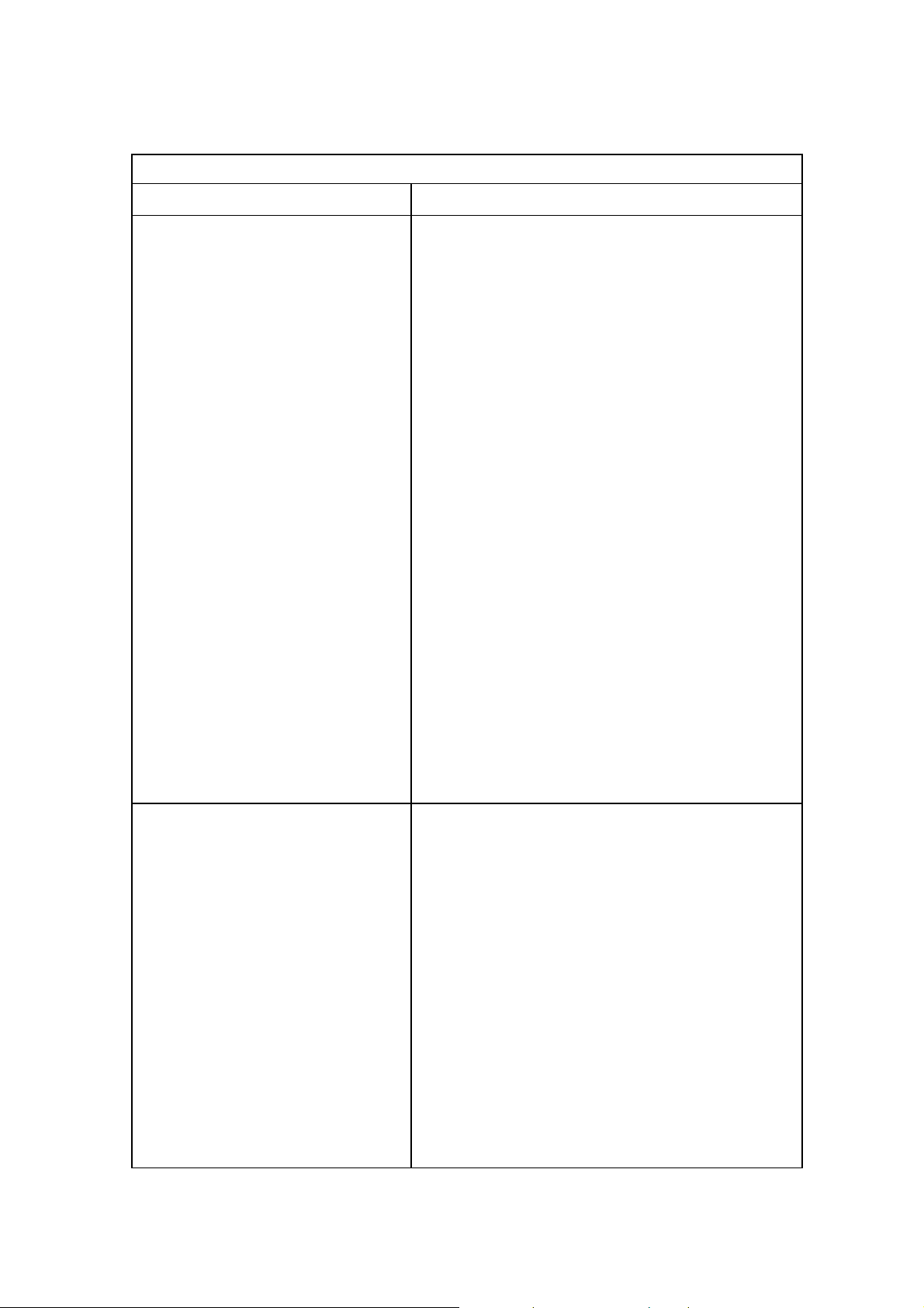
Accessories
Standard
Option
* The specifications are subject to change without notice
Owner's Instruction , Remote Controller/AAA Batteries , Power Cord
Foot Stand , Table-Top stand , Wall-Mount Bracket , Ceiling-Mount Bracket ,
Internal Speaker System , External Speaker System ,
DVI Cable , VGA(D-SUB) Cable , Audio Cable , Component Cable ,
RCA Video Cable , RCA Audio Cable , S-Video Cable , Scart Cable,
HDMI Cable , Optical Cable , Speaker Cable
Page 8

8/185
WoosungNextier Corp.
------------------------------------------------------------------------------------------------------------
Engineering Product Specification
MODEL
(BDS4241V/00, BDH4241V/00, BDH5021V/00)
PDP – MONITOR
Approved
WOOSUNG NEXTIER Corp .
DATE :
DATE :
Page 9

9/185
DISCLAIMER
WoosungNextier Corp. shall not be liable for technical or omissions contained
herein: nor for
incidental or consequential damages resulting from the furnishing, performance,
or use of this material.
WoosungNextier Corp. reserves the right to change any or all specifications without notice.
Information in this document may change without notice.
CONFIDENTIALITY
All material contained within this document is proprietary information and the sole
property of WoosungNextier Corp. #821~3, Byucksan Digital ValleyⅡ, 481-10, gasandong, Geumcheon-Gu, Seoul-city, Korea. No part of this document may be copied,
reproduced, or transmitted by any means, for any purpose without prior written
permission from WoosungNextier Corp.
Page 10

10/185
TABLE OF CONTENTS
1. SCOPE
1.1 Introduction.
1.2 Product Definition.
1.3 Mass Production Release.
1.4 Change Control.
1.5 Service.
2. GENERAL SPECIFICATION
2.1 General Spec.
2.2 Input / Output Terminal.
3. INPUT SIGNAL INTERFACE
3.1 DVI Signal Interface.
3.2 RGB Signal Interface.
3.3 DVI / RGB Mode Table.
3.4 Component Signal Interface.
3.5 Component Mode Table.
3.6 S-Video Signal Interface.
3.7 Composite Signal Interface.
3.8 SCART Signal Interface.
4. POWER
4.1 Power Supply.
5. CONTROLS AND INDICATORS
5.1 Hardware Control.
5.2 Remote control.
5.3 Menu Control
Page 11

6. PLASMA DISPLAY PANEL(PDP) Specifications
11/185
6.1 42”SD Specifications
6.2 42”HD Specifications
6.3 50”HD Specifications
7. DISPLAY CELL DEFECT SPECIFICATION
7.1 42”SD Cell Defect Specifications
7.2 42”HD Cell Defect Specifications
7.3 50”HD Cell Defect Specifications
8. MECHANICAL
8.1 Fan.
8.2 Dimension.(without stand)
8.3 Weight.
9. ENVIRONMENTAL
9.1 42”SD Environmental Conditions.
9.2 42”HD Environmental Conditions.
9.3 50”HD Environmental Conditions.
10. PACKAGING
10.1 Packaging Specifications.
10.2 Vibration.
10.3 Drop.
11. AUDIO SYSTEM
11.1 Internal Speaker System.
Page 12
1. SCOPE
12/185
1.1 Introduction
Product configuration
Plasma Displays
1.2 Product Definition
Top Level Assembly
This specification defines the configuration and performance
requirements for the following Plasma Displays.
Product Name : PDP-MONITOR
Display Type : 42” SD / 42” HD / 50” HD
Model Name :
BDS4241V/00, BDH4241V/00, BDH5021V/00
The top level assembly shall contain :
1. Plasma Display :
BDS4241V/00, BDH4241V/00, BDH5021V/00
2. Power Cord
3. Remote Control Unit
4. “AA” Batteries N=2
5. Owner’s Instructions
6. DVI & RGB(VGA) Cable
7. Foot Stand
8. Internal Speaker System
1.3 Mass Production Release
Mass Production Approval
Component Approvals
Mass Production shall not begin until Woosung
Nextier Corp. has issued a Mass Production
Release.
All exterior plastic components, screen printed components,
labels, shipping cartons, protective foam, and printed
materials require approvel by WoosungNextier Corp. prior to
Mass production Release.
Page 13
1.4 Change Control
13/185
All Engineering changes to the product shall be made in
ECR/ECN
1.5 Service
Documentation / Service Manual
accordance with the WoosungNextier Corp. ECR/ECN
Procedure
Complete Spare Parts List, Schematic, Service Manual, and
Assembly Drawings shall be provided within one month of
Mass Production Release.
Page 14
2. GENERAL SPECIFICATION
14/185
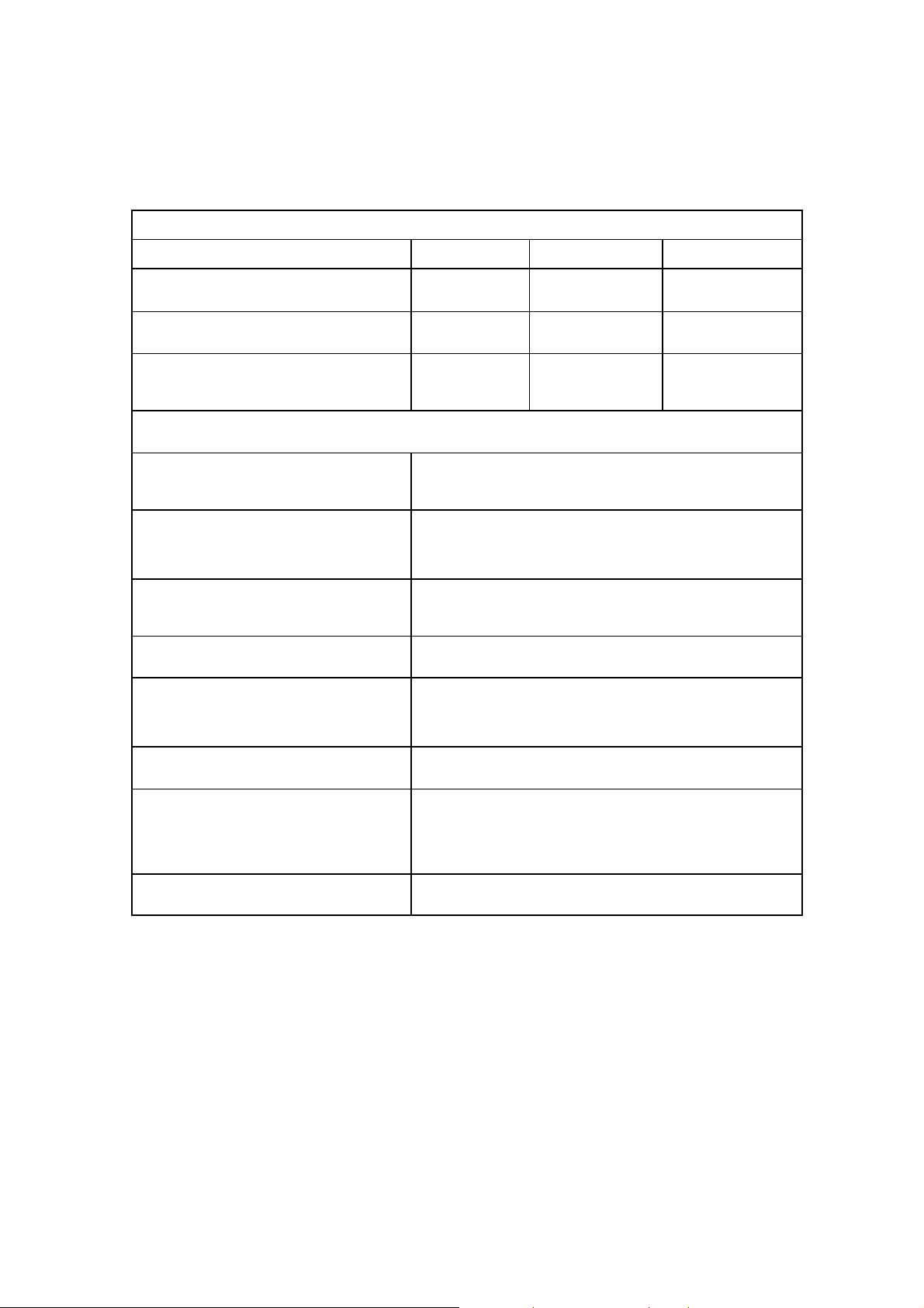
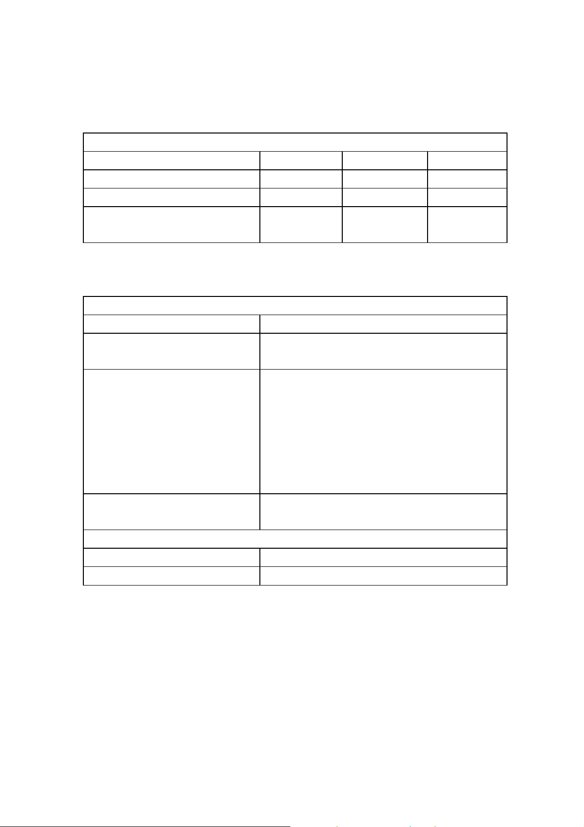
2.1 General Spec.
Display Type 42”SD 42”HD 50”HD
Model Name
Native Resolution & Frequency
BDS4241V/00 BDH4241V/00 BDH5021V/00
852 X 480 @ 60Hz 1024 X 768 @ 60Hz 1366 X 768 @ 60Hz
AC100V ~ 240V,
AC100V ~ 240V,
Input Voltage
50/60Hz
2.2 Input/Output Terminal
DVI Input
RGB Input
Component Input
S-Video Input Mini DIN S-terminal × 1
Composite Input RCA Jack × 1
DVI_D 24-pin Jack × 1
RCA Jack(L+R) × 1
D-Sub 15-pin Jack ×1
RCA Jack(L+R) × 1
RCA(YPbPr/YCbCr) Jack × 1
RCA(L+R) Jack × 1
50/60Hz
AC100V ~ 240V,
50/60Hz
SCART Input/Output or Scart 21-pin Jack × 2 (Full×1, Half×1)
Monitor Output RCA Jack × 1
RS-232C D-Sub 9-pin Jack × 1
Page 15
3. INPUT SIGNAL INTERFACE
15/185
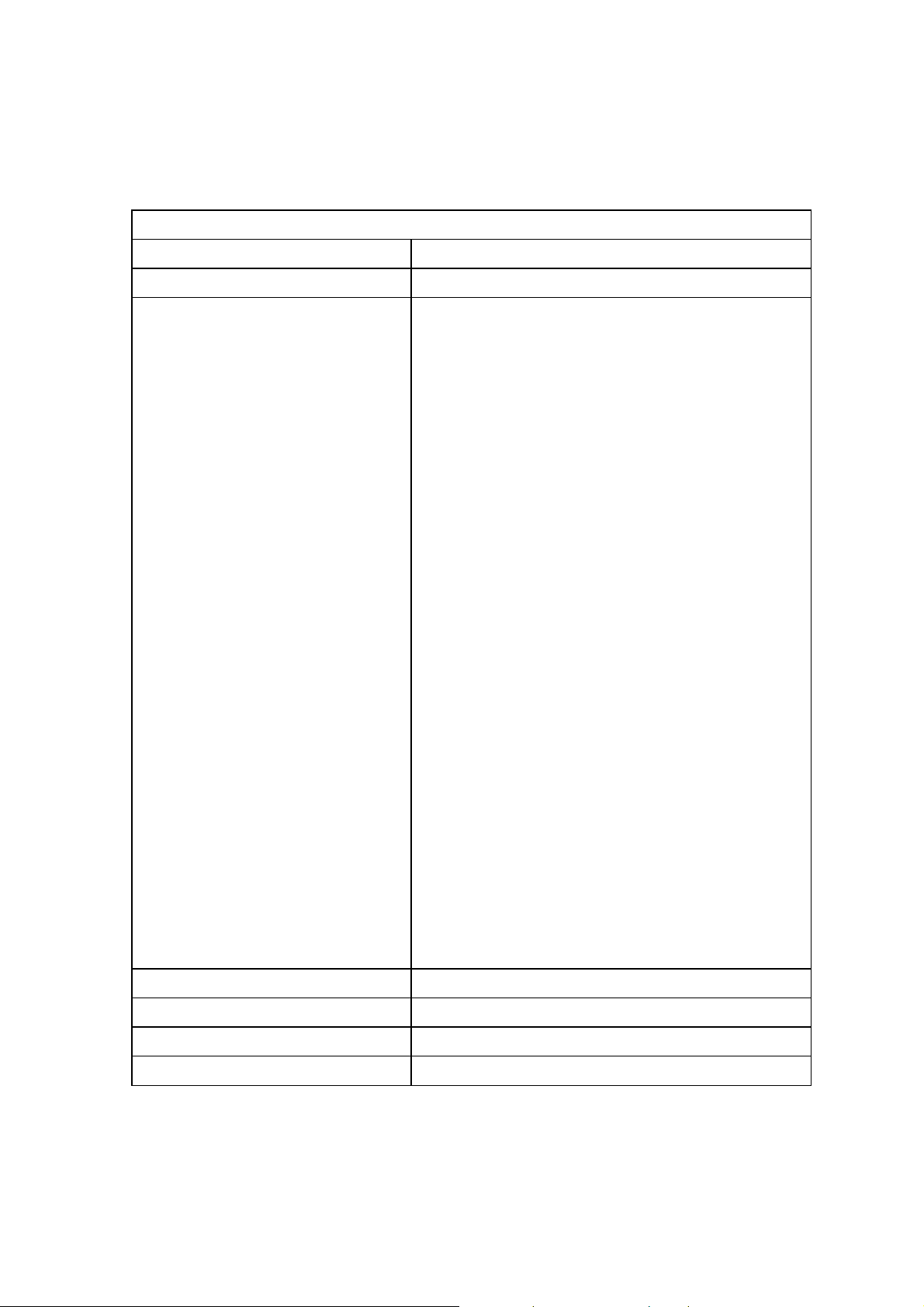
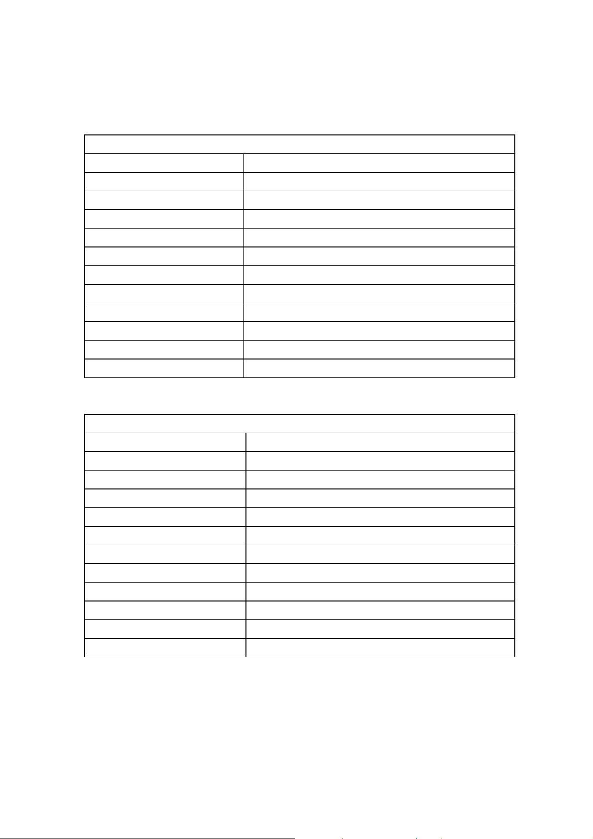
3.1 DVI Interface
DVI Input Connector DVI-D Female Contacts
Audio Input Connector RCA (L+R) Jack
DVI Video Cable Connector Pin out Pin 1 TMDS Data 2-
Pin 2 TMDS Data 2+
Pin 3 TMDS Data 2/4 Shield
Pin 4 TMDS Data 4Pin 5 TMDS Data 4+
Pin 6 DDC Clock
Pin 7 DDC Data
Pin 8 NC
Pin 9 TMDS Data 1Pin 10 TMDS Data 1+
Pin 11 TMDS Data 1/3 Shield
Pin 12 TMDS Data 3Pin 13 TMDS Data 3+
Pin 14 +5V Power
Pin 15 Ground (+5V)
Pin 16 Hot Plug Detect
Pin 17 TMDS Data 0Pin 18 TMDS Data 0+
Pin 19 TMDS Data 0/5 Shield
Pin 20 TMDS Data 5Pin 21 TMDS Data 5+
Pin 22 TMDS Clock Shield
Pin 23 TMDS Clock -
Pin 24 TMDS Clock +
Sync Signals Digital, Differential type (TMDS)
DVI Audio Input Level 0.5V[rms] (L+R)
DVI Signal Impedance
DDC 1/2B Ver. 1.3
Page 16
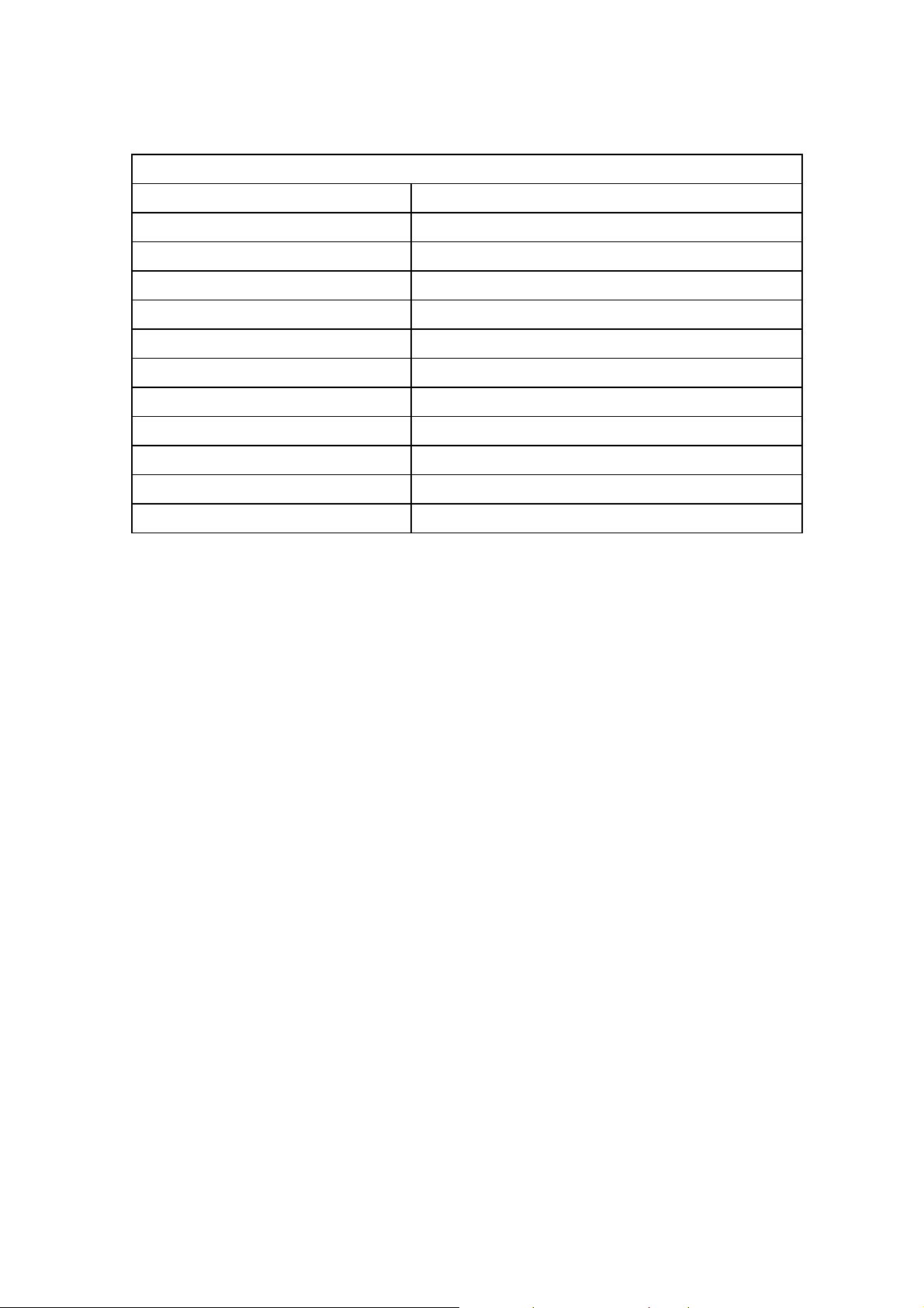
3.2 RGB Interface
16/185
RGB Input Connector D-Sub 15-Pin Jack (Female)
Audio Input Connector RCA (L+R) Jack
D-Sub 15-Pin Cable Connector Pin out
Pin 1 Red analog Signal
Pin 2 Green analog Signal
Pin 3 Blue analog Signal
Pin 4 GND
Pin 5 GND
Pin 6 GND for Red signal
Pin 7 GND for Green signal
Pin 8 GND for Blue signal
Pin 9 NC
Pin 10 GND
Pin 11 GND
Pin 12 SDA (Input only)
Pin 13 H-Sync or composited H/V Sync Signal
Pin 14 V-Sync
Pin 15 SCL (Input only)
RGB Signals 700 mV full scale
RGB Signal Impedance 75 Ohms
RGB Audio Input Level 0.5V[rms] (L+R)
RGB Audio Output Level 0.5V[rms] (L+R)
RGB Sync Signals TTL 2.2k ohm internal pull-up resistors.
DDC 1/2B VER 1.3(Option)
Page 17
3.3 DVI / RGB Mode Table
17/185
Mode Resolution Horizontal
Frequency(kHz)
VGA
SVGA
640 x 350 31.460 70.000 25.170
640 x 400 37.861 85.000 31.500
720 x 400 31.469 70.000 28.320
640 x 480
800 x 600
832 x 624 49.720 75.000 57.280
31.460 50.000 25.170
31.500 60.000 25.175
37.700 72.000 31.500
37.500 75.000 31.500
43.300 85.000 36.000
35.100 56.000 36.000
37.900 60.000 40.000
48.100 72.000 50.000
46.900 75.000 49.500
53.700 85.000 56.250
Vertical
Frequency (Hz)
Pixel Clock Frequency
(MHz)
XGA
SXGA 1280 x 1024 64.000 60.000 108.000
SDTV 480p 720 x 480 31.470 59.940 27.000
SDTV 575p 720 x 576 31.250 50.000 27.000
HDTV 720p 1280 x 720
HDTV 1080i 1920 x 1080
1024 x 768
1152 x 870 68.680 75.000 100.000
48.400 60.000 65.000
56.500 70.000 75.000
60.000 75.000 78.750
64.000 80.000 85.500
68.300 85.000 94.500
45.000 60.000 74.250
44.960 59.940 74.180
37.500 50.000 74.250
33.750 30.000 74.250
33.720 29.970 74.180
31.250 25.000 74.250
28.125 25.000 74.250
Page 18

18/185
3.4 Component Interface
Component Input Connector RCA(YPbPr/YCbCr) Jack
Audio Input Connector RCA(L+R) Jack
Component Signal Y : 1V[p-p]
Pb/Cb : 0.7V[p-p]
Pr/Cr : 0.7V[p-p]
Component Signal Impedance 75 Ohms
Audio Input 0.5[rms] (L+R)
Audio Input Impedance 470K Ohms
Component Signal Type EDTV : 525i(480i), 625i(576i)
SDTV : 625p(576p), 525p(480p)
HDTV : 750p(720p), 1125i(1035i, 1080i)
3.5 Component Mode Table
Mode Resolution Horizontal
Frequency
(kHz)
EDTV 480i 720 x 480 15.730 29.970 13.5000
EDTV 575i 720 x 576 15.630 25.000 13.5000
SDTV 480p 720 x 480 31.470 59.940 27.000
SDTV 575p 720 x 576 31.250 50.000 27.000
HDTV 720p 1280 x 720
HDTV 1080i 1920 x 1080
45.000 60.000 74.250
44.960 59.940 74.180
37.500 50.000 74.250
33.750 30.000 74.250
33.720 29.970 74.180
31.250 25.000 74.250
28.125 25.000 74.250
Vertical
Frequency
(Hz)
Pixel Clock Frequency
(MHz)
Page 19
19/185
3.6 S-Video Interface
S-Video Input Connector Mini DIN4-pin
S-Video Signal Y : 1V[p-p]
C : 0.286V[p-p] (NTSC)
C : 0.3V[p-p] (PAL/SECAM)
S-Video Signal Impedance 75 Ohms
3.7 Composite Interface
Composite Input Connector RCA(Video) Jack
Composite Output Connector RCA(Video) Jack
Audio Input Connector RCA(L+R) Jack
Audio Output Connector RCA(L+R) Jack
Composite Input Signal V : 1V[p-p]
Composite Output Signal V : 1V[p-p]
Composite Audio Input Level 0.5[rms] (L+R)
Composite Audio Output Level 0.5[rms] (L+R)
Composite Input Signal Impedance 75 Ohms
Composite Output Signal Impedance 75 Ohms
Composite Audio Input Impedance 470K Ohms
Composite Audio Output Impedance 220K Ohms
Page 20
3.8 Scart Interface
20/185
Scart Input Connector Scart 21-pin Jack
Scart1 21-Pin Cable Connector Pin out Pin 1 Audio R Out
Pin 2 Audio R In
Pin 3 Audio L (or Mono) Out
Pin 4 Audio Ground
Pin 5 RGB Ground Blue
Pin 6 Audio L (or Mono) In
Pin 7 RGB Blue In
Pin 8 FUNCTION SWITCHING
Pin 9 RGB Ground Green
Pin 10 N.C
Pin 11 RGB Green In
Pin 12 N.C
Pin 13 RGB Ground Red
Pin 14 Ground Data
Pin 15 RGB Red In / Chrominance In
Pin 16 Blanking Signal
Pin 17 Ground Composite signal
Pin 18 Ground Blanking Signal
Pin 19 Composite Video Out
Pin 20 Composite Video In / Luminance In
Pin 21 Ground / Shiled
Scart2 21-Pin Cable Connector Pin out Pin 1 Audio R Out
Pin 2 Audio R In
Pin 3 Audio L (or Mono) Out
Pin 4 Audio Ground
Pin 5 RGB Ground Blue
Pin 6 Audio L (or Mono) In
Pin 7 N.C
Pin 8 FUNCTION SWITCHING
Pin 9 RGB Ground Green
Pin 10 N.C
Pin 11 N.C
Pin 12 N.C
Pin 13 Chrominance Ground
Page 21
Pin 14 Ground Data
21/185
Pin 15 Chrominance In
Pin 16 N.C
Pin 17 Ground Luminance
Pin 18 Ground
Pin 19 Composite Video Out
Pin 20 Composite Video In / Luminance In
Pin 21 Ground / Shiled
Scart1 Input Signal
V : 1V[p-p]
RGB : 0.7V[p-p]
Scart2 Input Signal V : 1V[p-p]
Scart Output Signal V : 1V[p-p]
Scart Audio Input / Output Level 0.5[rms] (L+R)
Scart Input / Output Signal Impedance 75 Ohms
Scart Audio Input Impedance 470K Ohms
Scart Audio Output Impedance 220K Ohms
Page 22
4. power
22/185
4.1 Power Supply
Model Name BDS4241V/00 BDH4241V/00 BDH5021V/00
Input Voltage Range AC 100 ~ 240V AC 100 ~ 240V AC 100 ~ 240V
Input Frequency Range 50/60 Hz 50/60 Hz 50/60 Hz
Power Consumption Tpy : 290W
Standby : 7 W
Tpy : 350W
Standby : 7 W
5. CONTROLS AND INDICATORS
5.1 Hardware Controls
Main Power Switch None
LED Power / Standby : Red
Operation Lamp : Green
Controls Switch Input
Menu
VOL-
VOL+
CH-
CH+
Power
Tpy : 450W
Standby : 7 W
Infrad Receiver Arrival Distance : Min 7m
Resonance Frequency : 38 KHz
5.2 Remote Control
Distance 7 m
Angle 30 degrees angle on each side of the sensor
Page 23

5.3 Menu Controls
23/185
SCART /
Video /
S-Video
Input
Component
Input
RGB
Input
DVI
Input
Image Brightness, Contrast, Sharpness, Color, Tint, Image Preset
Screen Size, Freeze, Sticking Minimum
Setup Language, Sleep Timer, OSD Settings(Transparency, Timeout)
Audio Volume, Treble, Bass, Balance, Mute, Audio Preset
Image Same above
Screen Same above
Setup Same above
Audio Same above
Image Brightness, Contrast, Phase, Frequency, Sharpness, Image Preset
Screen Size, H Position, V Position, Auto, Freeze, Sticking Minimum
Setup Same above
Audio Same above
Image Brightness, Contrast, Sharpness, Image Preset
Screen Size, Freeze, Sticking Minimum
Setup Same above
Audio Same above
Page 24
6. PLASMA DISPLAY PANEL (PDP) SPECIFICATIONS
24/185
6.1 42” SD Specifications
Panel Type 42V7
Number of Pixels
Pixel Pitch
Cell Pitch
Display Area
Outline Dimension
Pixel Type RGB Closed type
Number of Gradations
Aspect Ratio 16:9
Peak Brightness
Contrast Ratio(in Dark Room) Typical 10,000:1
Life-time More than 60,000 Hours of continuous operation
6.2 42” HD Specifications
Panel Type 42X3
Number of Pixels
852(H) × 480(V) pixels (1pixel = 3 RGB cells)
1.080 mm (H) × 1.080 mm (V)
0.320 mm (H) × 1.080mm (V)
920.1mm (H) × 518.4mm (V) ± 0.5mm
1005(H) × 597(V) × 60.6(D) ± 1mm
(R)1024 × (G)1024 × (B)1024
Typical 1,500cd/㎡
1024(H) × 768(V) (1pixel=3 RGB cells)
Pixel Pitch
Cell Pitch
Display Area
Outline Dimension
Pixel Type RGB Closed type
Number of Gradations
Aspect Ratio 16:9
Peak Brightness
Contrast Ratio(in Dark Room) Typical 8,000:1
Expected Life-time More than 60,000 Hours of continuous operation
0.900 mm (H) × 0.676 mm (V)
0.300 mm (H) × 0.676 mm (V)(Green Cell basis)
921.5mm (H) × 519.0mm (V) ± 0.5mm
1005(H) × 597(V) × 60.7(D) ± 1mm
(R)1024 × (G)1024 × (B)1024
Typical 1,200cd/㎡
Page 25
6.3 50” HD Specifications
25/185
Panel Type 50X3
Number of Pixels
Pixel Pitch
Cell Pitch
Display Area
Outline Dimension
1366(H) × 768(V) (1pixel=3 RGB cells)
0.810 mm (H) × 0.810 mm (V)
0.270 mm (H) × 0.810 mm (V)(Green Cell basis)
1106.5mm (H) × 622.1mm (V) ± 0.5mm
1190(H) × 700(V) × 58(D) ± 1mm
Pixel Type RGB Closed (Well)type
Number of Gradations
(R)1024 × (G)1024 × (B)1024
Aspect Ratio 16:9
Peak Brightness
Typical 1,000cd/㎡
Contrast Ratio(in Dark Room) Typical 8,000:1
Expected Life-time More than 60,000 Hours of continuous operation
Page 26

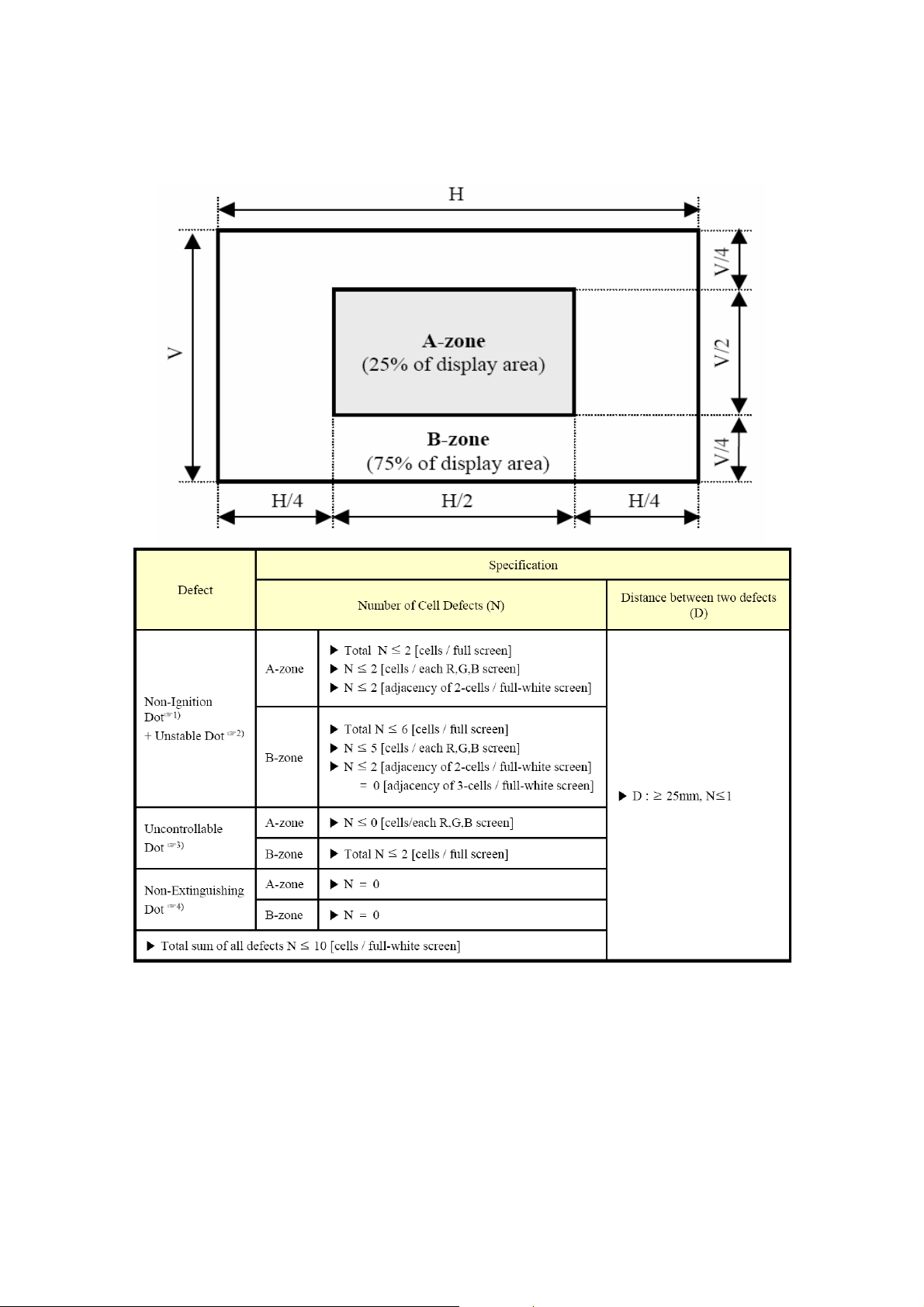
7. Display Cell Defect Specification
26/185
7.1 42” SD Cell Defect Specifications
☞1) Non-Ignition Dot(Dark Defect) is defined as “A cell of which more than 50% area is not ignited”
☞2) Unstable Dot (Flickering) is defined as “A cell which repeats On and Off”
☞3) Uncontrollable Dot is defined as “A cell which is distinctly brighter or darker than other cells around it” and/or
“A cell of which color is distinctly different from that of other cells around it”
☞4) Non-Extinguishing Dot (brightness defect) is defined as “A cell of which more than 50% area is always ON”
☞5) Stain is defined as “A blob due to local color contamination in white or simple color pattern”
*The decision distance is 3H away from the panel, intensity of illumination is between 100 Lux and 200 Lux.
Page 27
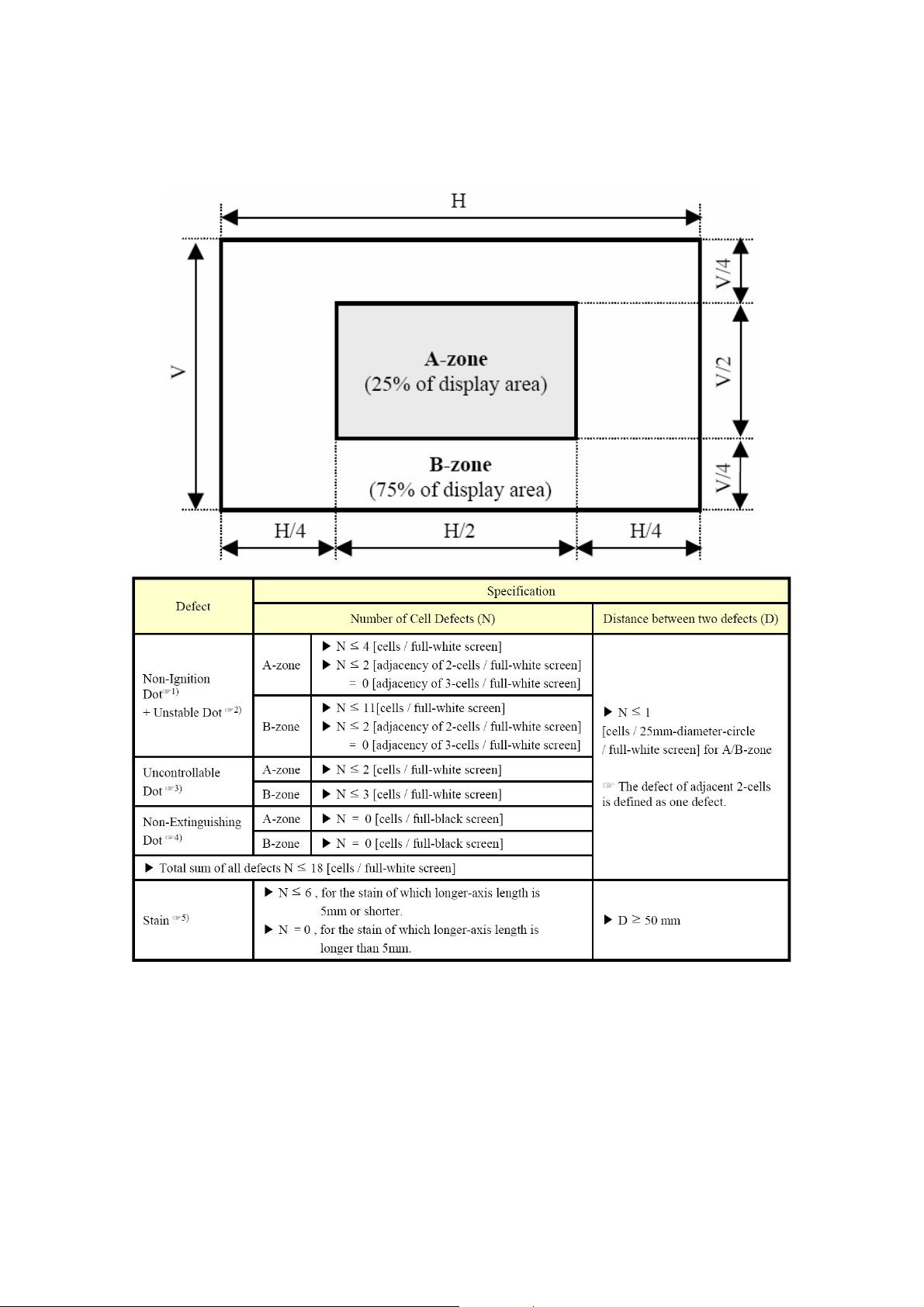
7.2 42” HD Cell Defect Specifications
27/185
☞1) Non-Ignition Dot(Dark Defect) is defined as “A cell of which more than 50% area is not ignited”
☞2) Unstable Dot (Flickering) is defined as “A cell which repeats On and Off”
☞3) Uncontrollable Dot is defined as “A cell which is distinctly brighter or darker than other cells around it” and/or
“A cell of which color is distinctly different from that of other cells around it”
☞4) Non-Extinguishing Dot (brightness defect) is defined as “A cell of which more than 50% area is always ON”
* The decision distance is 3H away from the panel, intensity of illumination is between 100 Lux and 200 Lux.
Page 28
7.3 50” HD Cell Defect Specifications
28/185
☞1) Non-Ignition Dot(Dark Defect) is defined as “A cell of which more than 50% area is not ignited”
☞2) Unstable Dot (Flickering) is defined as “A cell which repeats On and Off”
☞3) Uncontrollable Dot is defined as “A cell which is distinctly brighter or darker than other cells around it” and/or
“A cell of which color is distinctly different from that of other cells around it”
☞4) Non-Extinguishing Dot (brightness defect) is defined as “A cell of which more than 50% area is always ON”
☞5) Stain is defined as “A blob due to local color contamination in white or simple color pattern”
Page 29
8. MECHANICAL
29/185
8.1 Fan
Fans N/A (No Fans are used in the unit)
8.2 Dimensions (without stand)
Model Name BDS4241V/00 BDH4241V/00 BDH5021V/00
Width
Height
Depth
1028mm 1028mm 1206.7mm
625mm 625mm 721mm
89.8mm 107.4mm 117.3mm
8.4 Weight(without stand)
Model Name BDS4241V/00 BDH4241V/00 BDH5021V/00
Net Weight 28Kg 30Kg 42Kg
9. ENVIRONMENTAL
9.1 42”SD Environmental Conditions
Operating Temperature Range 0°C to +55°C
Storage Temperature -20°C to 60°C (Packing condition)
Operating Relative Humidity 20% to 80% (Non-Condensing)
Storage Relative Humidity 10% to 90% (Non-Condensing)
Operating Atmospheric Pressure 800~1100hpa (Altitude : 0 ~ 2,000 m)
Storage Atmospheric Pressure 700~1100hpa (Altitude : 0 ~ 3,000 m)
9.2 42”HD Environmental Conditions
Operating Temperature Range 0°C to +40°C
Storage Temperature -20°C to 60°C (Packing condition)
Operating Relative Humidity 20% to 80% (Non-Condensing)
Storage Relative Humidity 10% to 90% (Non-Condensing)
Operating Atmospheric Pressure 800~1100hpa (Altitude : 0 ~ 2,000 m)
Storage Atmospheric Pressure 700~1100hpa (Altitude : 0 ~ 3,000 m)
Page 30

9.3 50”HD Environmental Conditions
30/185
Operating Temperature Range 0°C to +40°C
Storage Temperature -20°C to 60°C (Packing condition)
Operating Relative Humidity 20% to 80% (Non-Condensing)
Storage Relative Humidity 10% to 90% (Non-Condensing)
Operating Atmospheric Pressure 800~1100hpa (Altitude : 0 ~ 2,000 m)
Storage Atmospheric Pressure 700~1100hpa (Altitude : 0 ~ 3,000 m)
10. PACKAGING
10.1 Package Specifications
Model Name BDS4241V/00 BDH4241V/00 BDH5021/00
Ink The ink shall not rub off after a suitable drying time.
Shipping Carton Type One Piece Construction
Carton Material Double Wall
Handle Cartons shall incorporate four holes on sides sides for
Width TBD TBD TBD
Height TBD TBD TBD
Depth TBD TBD TBD
Gross Weight TBD TBD TBD
Vertical Flute
16 kg/cm2 burst strength.
handling.
10.2 Vibration
Bottom Back and Sides
Vibration Frequency 5-30Hz 30-50Hz 5-50Hz
Acceleration 1.1G 0.7G 0.7G
Duration 15minutes / 1 cycle 15minutes / 1 cycle
Test Time 75minutes 15minutes
Vibration Test Data
10.3 Drop
Bottom 30cm
Four Bottom Edges (one side support) 40cm (another side edge support at 15cm height )
Drop Test Data
Page 31

11. AUDIO SYSTEM
31/185
11.1 Internal Speaker System
Type 2 Way 2 Speaker System
Input 10 W (RMS)
Impedence 8 ohm
Output Sound Pressure 88 dB/W/M
Frequency Response 140 Hz ~ 10 KHz
Page 32

BLOCK DIAGRAM
32/185
Model :
Philips Europe
Ver.03
2006.04.04
Control Board
MenuInput
- VOL +
-CH +
LED
IR
RS-232C
DVI Input
RGB Input
Componet
Input
RXD
TXD
EEPROM
1K Byte
Audio_DVI
EEPROM
1K Byte
HV
RGB
Audio_RGB
YPbPr1
Audio_C1
TMDS_DVI
74ACT08A
MAX232
Transmitter
/Receiver
RXD_u
TXD_u
RGB_Scart
SC1[V] (SOG)
YC_out2
TMDS_DVI
YPbPr1
HV
RGB
SDRAM
16Mbit
PW2300-10
PW3300-10
Flash ROM
8M Bit
PW318-10
DDR SDRAM
256Mbit
RXD_u
TXD_u
EEPROM
32K Byte
Main Board
PDP
&
LCD
Module
Power
Regulator
Monitor
Output
S-Video Input
Video Input
Scart 2
(YC)
Scart 1
(RGB)
V_out1
LR_Out
V1,SV1,L1,R1
V_out1
SC1_LR_Out
SC2[V(Y),C,L,R]
V_out2
SC2_LR_Out
SC1[V,L,R]
RGB_Scart
SDRAM
16Mbit
YC_out1
TA8851
V_out1
V_out1
YC_out2
V_out2
V_out2
Audio_C1
V1,SV1,L1,R1
V2,SV2,L2,R2
SC1[V,L,R]
SC2[V(Y),C,L,R]
SC2[V(Y),C,L,R]
SC1[V,L,R]
RGB_Scart
V1,SV1,L1,R1
RGB_Scart
SC1[V,L,R]
V1,SV1,L1,R1
SC2[V(Y),C,L,R]
LR_out1
LR_out2
Audio_DVI
Audio_PC
LR_Out
SC1_LR_Out
LR_Out
SC1_LR_Out
SC2_LR_Out
SC2_LR_Out
MSP4450G
I2S
SC1_LR_Out
SC2_LR_Out
Loud_LR_Out
LR_Out
TA2024B
Rmain
Lmain
Phone JACK
Rext
Lext
Rint
Lint
Rint
Lint
Internal
Speaker
Output
R
L
Rext
Lext
External
Speaker
Output
R
L
Sub Board
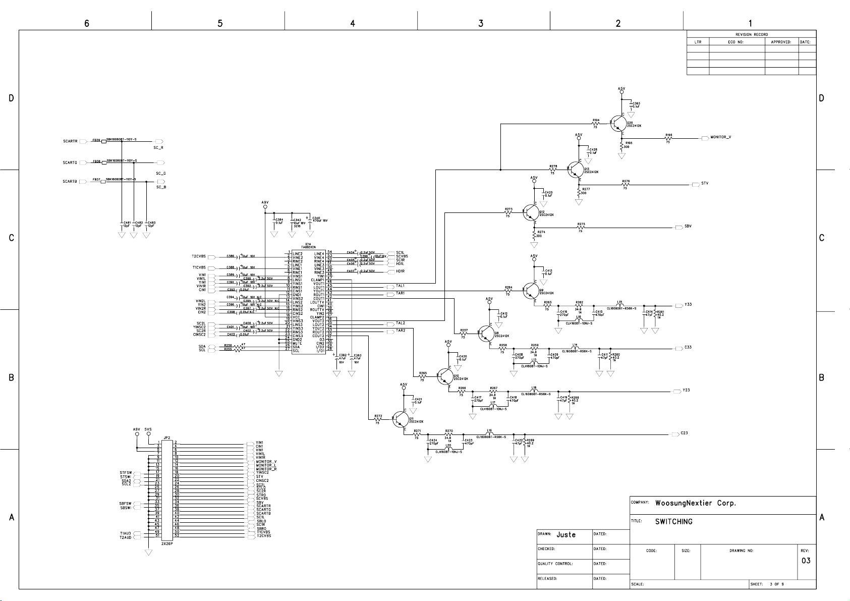
Page 33
NP-42S4-Main-03(06.04.03).sch-1 - Tue Apr 04 15:44:58 2006
33/185
Page 34

NP-42S4-Main-03(06.04.03).sch-2 - Tue Apr 04 15:44:58 2006
34/185
Page 35

NP-42S4-Main-03(06.04.03).sch-3 - Tue Apr 04 15:45:01 2006
35/185
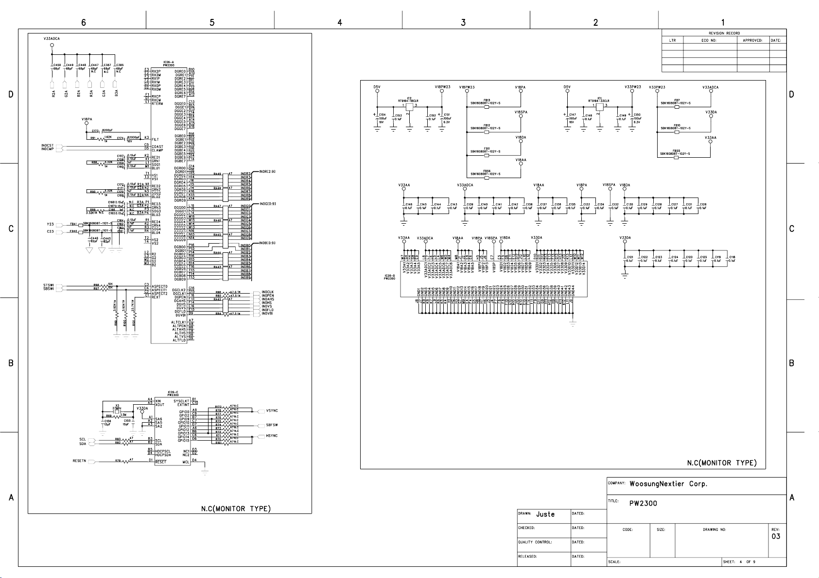
Page 36
NP-42S4-Main-03(06.04.03).sch-4 - Tue Apr 04 15:45:07 2006
36/185
Page 37
NP-42S4-Main-03(06.04.03).sch-5 - Tue Apr 04 15:45:09 2006
37/185
Page 38

NP-42S4-Main-03(06.04.03).sch-6 - Tue Apr 04 15:45:25 2006
38/185
Page 39

NP-42S4-Main-03(06.04.03).sch-7 - Tue Apr 04 15:45:46 2006
39/185
Page 40

NP-42S4-Main-03(06.04.03).sch-8 - Tue Apr 04 15:45:49 2006
40/185
Page 41

NP-42S4-Main-03(06.04.03).sch-9 - Tue Apr 04 15:45:59 2006
41/185
Page 42

NP-42S4-Main-03(06.04.03).sch-10 - Tue Apr 04 15:45:59 2006
42/185
Page 43

43/185
Page 44

NP-42S4-SUB-03(20060213).sch-2 - Tue Apr 04 15:48:23 2006
44/185
Page 45

NP-42S4-Control-02.sch-2 - Tue Apr 04 15:49:57 2006
45/185
Page 46

NP-42S4-Control-02.sch-1 - Tue Apr 04 15:49:57 2006
46/185
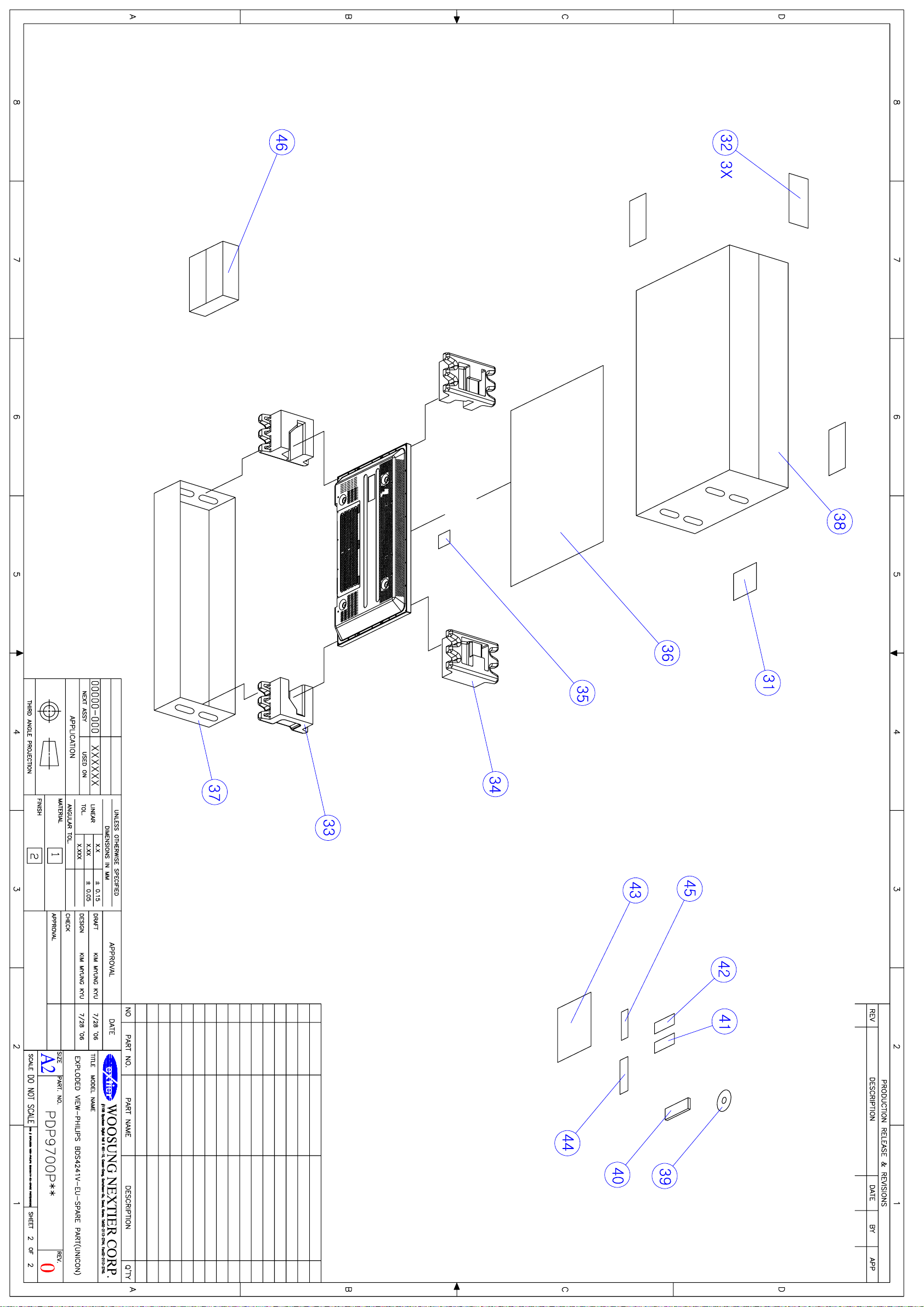
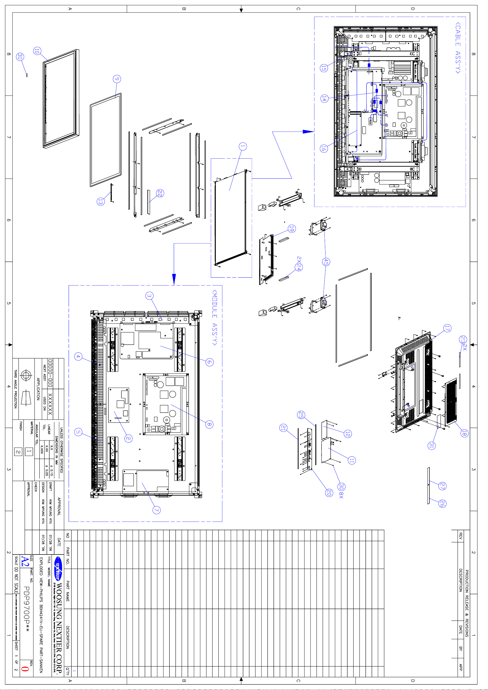
Page 47

47/185
EXPLODED VIEW
1. BDS4241V/00(CRS1.1(PCB 02/ PCB 02P, UNICON PSU))---48
2. BDH5021V/00(CRS1.1(PCB 02P, UNICON PSU))----------50
3. BDS4241V/00(CRS2.0(PCB 03, SEM PSU))--------------52
4. BDH4241V/00(CRS2.0(PCB 03, SANKEN PSU))----------54
5. BDH5021V/00(CRS2.0(PCB 03, LG PSU))---------------56
Page 48

48/185
Page 49
49/185
Page 50

50/185
Page 51

51/185
Page 52

52/185
Page 53

53/185
Page 54
54/185
Page 55

55/185
Page 56

56/185
Page 57

57/185
Page 58

58/185
CALIBRATION METHODS
1. Application limits
This test is applied to PDP 42” or PDP 50” production of WoosungNextier Corp.
2. Application Model : BDS4241V/00,BDH4241V/00,BDH5021V/00
3. The General
3.1 All of adjustments is applied in this test of adjustment but for exceptional
condition.
3.2 This test of inspection can be modified according to transition of production
And the alteration can be dependent upon judgment of production Team & R&D Team.
4. The Conditional :
This inspection is tested in 20 C of standard temperature, the additional 65%
Standard humidity.
5. The additional :
This test can be questioned to R&D department if you have question.
Registered Date ( )Team Opinion
Distributor
• Must no distributing
Whole words
• Cover Distributor
WoosungNextier Corp.
Page 59

6. Calibration
59/185
6.1 PSU Test of adjustment
1) Audio Voltage Test of adjustment
(1) Checking that the Audio Voltage Selection switch is selected to 240V.
If it is selected to 30V please switch to 24V.
2) PSU Driving Method Test
(1) Please check that PSU Driving Method Switch of PSU must be selected to
“Normal”
Page 60

6.2 TV Tuner Setting
60/185
1) Model of One Tuner Setting [Depend on Model]
(1) TV Input can be added up through processing below method.
(2) Please keep pushing [Power] + [CH+] button in 7 ~ 8 second after pushing
[Power] button.
(3) Please operate adjustment and inspection by selecting TV Input after
Checking that TV Input was added up by pushing [INPUT] button.
(4) TV Input can be deleted through processing below method.
(5) Please keep pushing [Power] + [CH-] button in 7 ~ 8 second after pushing
[Power] button.
(6) Please check that TV input was gone by pushing [Input] button.
And then select the Scart1 input for operating adjustment and inspection
2) Model of Two Tuner Setting [Depend on Model]
(1) Main/Sub TV Tuner can be added up through processing below method.
(2) Please keep pushing [Power] + [CH+] button in 7 ~ 8 second after pushing
[Power] button.
(3) Please Check that Main TV Input was added up by pushing [INPUT] button.
(4) Please keep pushing [Power] + [VOL+] button in 7 ~ 8 second after pushing
[Power] button.
(5) Please excel PIP or PBP screen by pushing [SPLIT] button
(6) Please select Sub screen by pushing [S.SELECT] in remote control
(7) Please check that Sub TV input was added in sub input by pushing
[Input] button.
And then select the TV input for operating adjustment and inspection
(8) Sub TV Input can be deleted through processing below method.
(9) Please keep pushing [Power] + [VOL-] button in 7 ~ 8 second after pushing
[Power] button.
(10) Please select Sub screen by pushing [S.SELECT] in remote control
(11) Please check that Sub TV input was deleted in sub input by pushing
[Input] button.
And then select the Scart1 Input for operating adjustment and inspection
Page 61

61/185
3) Monitor Setting without TV Tuner.[Depend on Model]
(1) Please delete TV Tuner in Monitor Setting through processing below method
(2) Please keep pushing [Power] + [CH-] button in 7 ~ 8 second after pushing
[Power] button.
(3) Please check that TV input was gone by pushing [Input] button.
And then select the Scart1 input for operating adjustment and inspection
6.3 Panel Selection[Depend on Panel]
(1) Value of Panel Selection can be changed as like below through
Pushing [VOL+], [CH-] and [CH+] then [Panel Select] OSD is shown.
(2) Push [VOL-] or [VOL+] button to select panel.
000 : 42”SD(Default) panel is selected
001 : 42”HD panel is selected
002 : 50”HD panel is selected
003 : LCD panel is selected
(2) Pease push power button off and power button on after OSD menu is placed
In the middle of screen by pushing [MENU] button – That means panel choice
Is selected in right.
(3) If OSD Menu is not placed in the middle of screen return to No.(1) as
Pushing [VOL+], [CH-] and [CH-] button at the same time.
(4) Please check the correct panel by viewing OSD Menu after Power On.
Page 62

6.4 Calibration
62/185
1) RGB Calibration
(1) Please connect RGB Input to 15 Pin D-sub cable
(Video Signal Output: Digital Video Generator VG-848 (ASTRO))
(2) Please adjust Timing of output (Video signal) to 640 x 480 / 75Hz
(3) Please adjust pattern (Video signal Output) to 16-Gray
(GRAY Direct Key of ASTRO REMOTE BOX)
(4) Please push [MENU] + [VOL-] + [VOL+] at the same time after Power On
(5) After operating RGB Calibration please adjust output pattern of video signal
to 64-gray + RGBW color bar and then check the extent of saturation of RGB
color and the difference of RGB color and unnecessary chrominance signal came
up in screen. If calibration is wrong after that please return to No.(3).
2) Component Calibration
(1) Please connect Component Input to RCA cable
(Video Signal Output : Digital Video Generator VG-848 (ASTRO))
(2) Please adjust Timing (Video signal out) to 720 x 576 / 50Hz (576p)
(3) Please adjust Pattern (Video signal out) to SMPTE Color Bar.
(4) Please push [MENU] + [VOL-] + [VOL+] at the same time after Power On.
(5) After operating RGB Calibration please adjust output pattern of video signal to
64-gray + RGBW color bar and then check the extent of saturation of RGB color
and the difference of RGB color and unnecessary chrominance signal came up in
screen. If calibration is wrong after that please return to No.(3).
Page 63

Image Board Inspection Methods
63/185
1. Application Limits
This instruction is applied to the inspection of PDP Products.
2. Application Model: BDS4241V/00, BDH4241V/00, BDH5021V/00
3. The General
3.1 This test of Inspection is applied to set which is adjusted accurately according to the
Inspection of BDS4241V/00, BDH4241V/00, BDH5021V/00
3.2 This test of Inspection can be modified according to transition of production Team and R &D
department.
4. The Conditional :
This inspection is tested in 20℃ standard temperature, 65% standard humidity.
5. The additional :
This inspection can be tested in normal temperature and normal humidity.(15~35℃, 45~85%)
The Registered date ( )team Opinion
Distributor
• No distributing
Whole words
• Cover distributor
WoosungNextier Corp.
Page 64

6. Inspection Items
64/185
6.1 General Specification
1) In/Out Terminals Spec.
2) Speaker Output Spec.
6.2 Inspection of Standardization
1) Pattern
2) Speaker Output
3) Input/Output
6.3 Inspection of the function of electric circuit
1) LED On/Off Test
2) KEY PAD / REMOTE CONTROLER Test
3) SCART 1,2 Input
4) VIDEO Input
5) Monitor Output
6) S-VIDEO Input
7) COMPONENT Input
8) RGB Input
9) DVI Input
10) RS232C Control TEST
11) Image Menu
12) Screen Menu
13) Setup Menu
14) Sound Menu
15) Remote controller
Function Key Test :
Mute, Locate, SIZE, SWAP(Swap), A.SWAP(Audio Swap),
Split Screen, S.SELECT, Input (Input choice),
Auto(Auto default), I.SIZE(choice of screen size),
FREEZE(Screen), Recall(Input),
Sleep(Reservation of Sleep)
Page 65
65/185
6.4 Out Going Specification
1) Menu Mode Selection.
7.1 The test of Inspection
1) In/Out Terminals Spec.
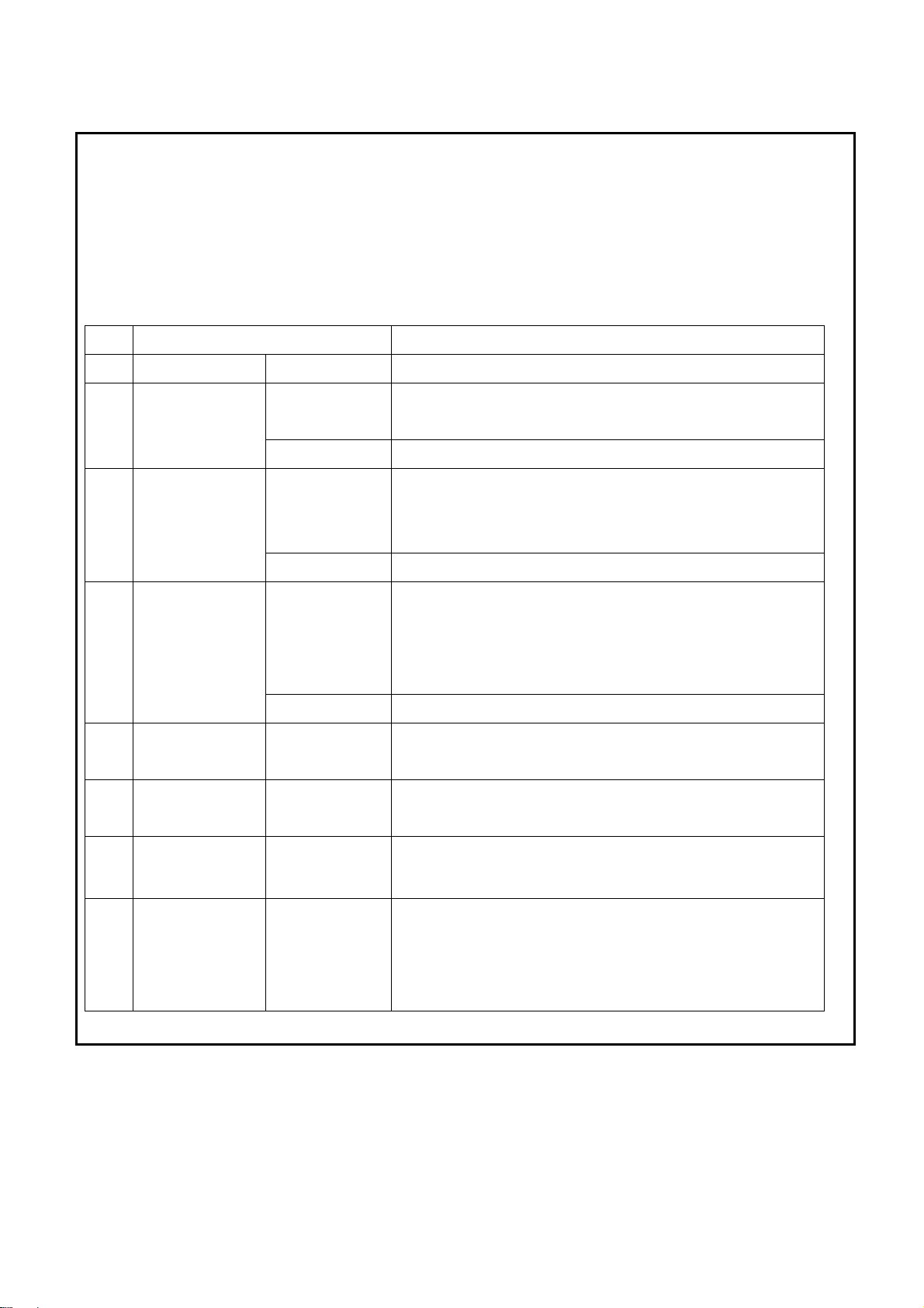
NO. ITEM SPECIFICATION
1 RS-232C
2
DVI
Input
3
RGB
Input
4
Component
Input
5
Monitor Output
6
S-Video Input
D-Sub 9-pin x 1
DVI Jack x 1
(24 Pin)
RCA Jack x 1
D-Sub Jack x 1
(15 Pin)
RCA Jack x 1
RCA Jack x 1
RCA Jack x 1
RCA Jack x 1
Mini DIN Jack x 1
(4 pin)
TXD/RXD(1:1)
Digital RGB : TMDS
MAX : 720p , 1080i , 1280 x 1024 / 60 Hz (SXGA)
Audio : 0.5V[rms](Normal)/2 Channel (L+R)
Analog RGB : 0.7V[p-p](75Ω), H/CS/V:TTL(2.2 kΩ),
SOG:1V[p-p](75Ω)
MAX : 720p, 1080i,1280 x 1024 / 60 Hz(SXGA)
Audio : 0.5V[rms](Normal)/2 Channel (L+R)
Y:1V[p-p](75Ω)
Pb/Cb:0.7V[p-p](75Ω),
Pr/Cr:0.7V[p-p](75Ω)
EDTV : 480i, 576i, 576p, 480p, 720p, 1080i
Audio : 0.5V[rms](Normal)/2 Channel (L+R)
Video : 1V[p-p] (75 Ω)
Audio : 0.5V[rms](Normal)/2 Channel (L+R)
Y: 1V[p-p] (75 Ω), C: 0.286V[p-p] (75 Ω)[NTSC]
Y: 1V[p-p] (75 Ω), C: 0.300V[p-p] (75 Ω)[PAL/SECAM]
7
Video Input
8 Scart 1,2
RCA Jack x 1
Scart Jack x 2
(21 pin)
[Full x 1,
Half x 1]
Video : 1V[p-p] (75 Ω)[NTSC/PAL/SECAM]
Audio : 0.5V[rms](Normal)/2 Channel (L+R)
Video : 1V[p-p] ( 75 Ω)
Y : 1V[p-p] ( 75 Ω), C : 0.3V[p-p] ( 75 Ω)
RGB : 0.7V[p-p] ( 75 Ω)
Audio : 0.5V[rms](Normal)/2 Channel (L+R)
Page 66

66/185
2) Speaker Output Spec.
(1)Internal speaker
NO. ITEM SPECIFICATION UNIT REMARK
1 Freq. Response 0.14 ~ 10 KHz Speaker Output
2 T.H.D Max. : 5 % 400Hz 10W
3 Output 10 + 10 W RMS
4 Impedance 8 + 8 Ω
5 Output sound pressure 88 dB/W/M
7.2 Inspection of Standardization
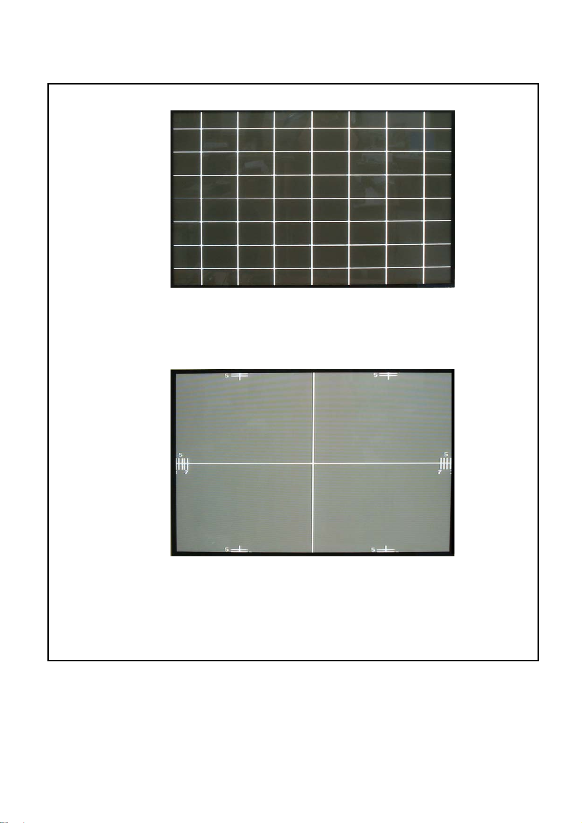
1) TEST PATTERN
(1) MONO SCOPE
Item Condition Standard Value
Resolution
More than 400 (H)
Standard Mode
OVER SHOOT Same as above Can be recognized
PRE SHOOT ″ ″
Horizontal ±120lines ~ ±480lines
Frequency Sync. Range MONOSCOPE
Vertical - 15lines - 9lines
MONOSCOPE
MONOSCOPE
Horizontal Less than +10%
The half of
OVER SCAN
Bright.
Vertical Less than +10%
Contrast Max.
ON SCREEN Remarking
MONOSCOPE Should not be cut in a picture
Position
The central cross line of RETMA PATTERN PDP
Vertical CENTER
RETMA PATTERN
Should match the Panel of mechanical CENTER
Adjustment
(Clear Screen)
Vertical CENTER ±5mm
Horizontal CENTER
The Central vertical line of RETMA PATTER
Same as above
Adjustment
Should balance in left/right. CENTER ±10mm
Page 67

<MONO SCOPE>
67/185
(2) Stair 10-Steps
- Checking the extent of saturation of left & right black & white pattern
- It Should be saturated less than black 2 step, white 2 step in left & right
- Checking unnecessary chrominance signal came up except black & white sync.
- Checking distortion and noise in a screen
< Stair 10-Steps>
(3) Color Bar
- Checking the reiterations of contacting side in each color bar
- Checking the difference of color in each color bar
- Checking the distortion and noise in screen
White
Cyan
Yellow
Green
Red
Green
Magenta
Black
<PAL, PAL-M, PAL-N> <NTSC,NTSC-4.43MHz>
<Full Color Bar>
White
Cyan
Yellow
Green
Red
Magenta
blue
Page 68

68/185
(4) Multi Burst
- Checking the range of Frequency Response
- Checking the distortion and noise in screen
< Multi burst>
Color System NTSC, NTSC-4.43MHz PAL, PAL-M, PAL-N, SECAM
Multi-Burst
0.5-1.0-2.0-3.0-3.58-4.2MHz 0.5-1.0-2.0-3.0-4.0-4.8MHz
Frequency
Frequency
Within 1.0dB Within 1.0dB
characteristic
Setup 0% 7.5%NTSC only 0%
White REF Signal 714.3mV 714.3mV 700.0mV
Multi-Burst
357.2mV 384.0mV 385.0mV
pedestal
Black level 0mV 53.6mV 0mV
Page 69

69/185
(5) Cross Pattern
- Checking something dropped out of horizontal, vertical line
- Checking the same interval between Crosshatch
- Checking the distortion and Noise
< Cross Pattern 16:9>
Line
system
Black Level 0%setup NTSC only 53.6 mV
NO. of horizontal crosshatch 17 23
No. of vertical crosshatch 13 13
Pulse width
Horizontal
Vertical
Crosshatch width
Horizontal
Vertical 525system
625system
Aspect ratio
4:3 16:9
White Level 0%setup 525 625 525 625
White Level 0%setup 714.3mV 700.0mV 714.3mV 700.0mV
NTSC only 714.3mV 714.3mV
Black Level 0%setup 0 mV 0 mV 0 mV 0 mV
53.6mV
296ns±100ns
2.96us±0.3us
2 lines
2.22us±0.3us
36 lines
44 lines
296ns±100ns
2 lines
36 lines
44 lines
Page 70

70/185
(6) 64-gradation block gray
- Checking the saturation of between splinter
- Seeing the difference of Brightness/Contrast
- Checking the distortion and noise in screen
<64-Gradation Block Gray>
(7) Crosshatch & circle & gray
<Crosshatch & Circle & Gray>
Page 71

71/185
- Checking that it is something dropped out of in horizontal, vertical line of crosshatch
- Checking that the interval between crosshatch line is equal
- Checking that printing-out of exact circle shape is right
- Checking brightness, contrast through gray pattern
- Checking that the distortion and noise is in screen
(8) Crosstalk
- Checking that Burst line is clear
- Checking that there is no distortion and noise
< Crosstalk>
(9) 8-black Crosshatch
- Checking that it is something dropped out of in horizontal, vertical line of crosshatch
- Checking that the interval between line is equal
- Checking that there is no distortion and noise
Page 72
72/185
<8-black Crosshatch>
(10) Display Position
< Display position>
- Checking the balance of left & right & top & bottom in a base of vertical line of center.
- Checking that the horizontal line of center should match the mechanical center of PDP Panel.
- Checking that there is no distortion and noise
Page 73

(11) SMPTE RP-133
73/185
- Checking that it is something dropped out of in horizontal, vertical line of crosshatch
- Checking that there is no problem of handling high frequency Sync.
- Checking Multi-bust Signal Frequency
- Checking that there is no distortion and noise
]
< SMPTE RP-133>
(12) 256Gray+RGBW Color Bar
- Checking the reiterations of contacting side In each color bar
- Checking that the printing-out of color is right
- Checking the range if Saturation
- Checking that there is no distortion and noise
<256gray+RGBW color bar>
Page 74

※(1)~(5) Pattern is the standard of ShibaSoku (TG-19CC) Signal
74/185
and (1) ~(5) Pattern is applied to VIDEO and S-VIDEO Input.
※(6)~(12) Pattern is the standard of ASTRODESIGN(VG-848) Signal
and (6) ~ (12) Pattern is applied to RGB, DVI, Component Input.
※(6)~(12) Pattern is the standard of MASTER(MSPG-1025S) signal
and (6)~(12) pattern is applied to SCART1,2 Input.
2) Speaker Output
Item Condition of Inspection Standard
Signal/Noise
Ratio
Signal/Buzz
Ratio
Max. Audio
output
Sound : 1KHz, more than 30% MODULATION
Picture : Black
50mW
Sound : 1KHz, more than 30% MODULATION
Picture : COLOR BAR
50mW
Sound : 1KHz, 100% MODULATION
Volume : Max.
More than 37dB
More than 35dB
More than 9 W
8Ω Resistance
Page 75

75/185
3) Input/Output
Input Condition standard
Video Input Video No any distortion & noise in Screen
Y,C No any distortion & noise in Screen S-Video Input
Audio No any noise in audio
Video No any distortion & noise in Screen
Monitor Output
Audio
No any distortion & noise in Audio
(L + R)
Y, Pb(Cb), Pr(Cr) No any distortion & noise in Screen
Component Input
Audio No any distortion & noise in Audio
Analog RGB No any distortion & noise in Screen
R,G,B Input
Audio No any distortion & noise in Audio
Digital RGB No any distortion & noise in Screen
DVI Input
Audio No any distortion & noise in Audio
RGB, CVBS Input No any distortion & noise in Screen
SCART1 Input
Audio No any distortion & noise in Audio
Y/C, CVBS Input No any distortion & noise in Screen
SCART2 Input
Audio No any distortion & noise in Audio
※ Video Signal Cross-Talk Level
- Should not be hindered by other signal input when signal inputs all inputs of signal
Page 76

76/185
7.3 Test of function of electric circuit
1) LED 0n/Off Test
(1) Checking that the stand-by signal –red- is lighting on
(2) Checking that working condition(power on) –green- is lighting on
2) KEY / REMOCON Test
(1) Push MENU key of front or remote control and check adjustment like below Box.
MENU
Move[-VOL+] Select[-CH+] EXIT[Menu]
Page 77

3) SCART 1,2 Input
77/185
(1) Please connect DVD Player to one side SCART input as SCART Cable
(2) Please connect Test of output to other side of SCART as SCART Cable.
(3) Pleas power on by pushing [POWER]key or front or remote controller
(4) Please select SCART 1,2 through [-VOL+], [-CH+] key after pushing [INPUT]key
INPUT
SCART1
SCART2
.
(5) Please select RGB, COMPOSITE Out Mode from SETUP MENU of DVD player.
(6) Please check the video signal in each mode is good in screen
(7) Please check that the Video & Audio signal in other side of SCART is well-being.
(8
) Please check that Sound is working well by pushing [-VOL+]key of front or remote controller
* SCART1 : The mode of RGB, Composite input are tested in all because of Full Scart.
* SCART2 : The mode of Y/C, Composite input is tested because of Half Scart.
4) VIDEO Input
(1) Please connect the signal of VIDEO Input to VIDEO Input as RCA Cable
(2) Please power on by pushing [POWER]key of front or remote controller
(3) Please select VEDEO Input by using [-VOL+] and [-CH+]key after pushing [INPUT]key
INPUT
SCART1
SCART2
VIDEO
.
(4) Please check that the video signal in each mode is working well
(5)
Please check that Sound is working well by pushing [-VOL+]key of front or remote controller
Page 78

78/185
5) Monitor Output
(1) Please connect VIDEO Input signal to VIDEO Input as RCA Cable
(2) Please connect the output of test installation to Monitor output as RCA Cable
(3) After connecting 8 Ω dummy resistance to speaker output in reft, right please connect
Multi-Meter to in each edge of dummy resistance
(4) Please power on by pushing [POWER]key of front or remote controller
(5) Please select VIDEO through [-VOL+] and [-CH+]key after pushing [INPUT]key
INPUT
.
VIDEO
.
(6) Please check that All in-coming video signal is working well
(7) Please check that Video signal is appearing in Monitor Output
(8) Please adjust Audio sound with max through [–VOL+]key of owner’s remote controller
(9) Please check that the maximum of incoming Audio signal is more than 8.8V[rms]
(10) Please check 8 Ω in left & right of speaker output and Multi-Meter
(11) Please check that audio sound is good by pushing [-VOL+]key
(12) Please check that Video signal(V) and Audio signal(R+L) is having right output
Page 79

79/185
6) S-VIDEO Input
(1) Please connect S-VIDEO terminal as S-Video Cable to S-VIDEO output
(2) Please connect Audio input terminal as RCA Audio Cable to Audio output
(3) Please power on by pushing [POWER]key of front or remote controller
(4) Please select S-VIDEO by pushing [-VOL+] and [-CH+]key after [INPUT]key
INPUT
.
S-VIDEO
.
.
(5) Please check all video signal in each mode is having good input in screen
(6) Please check the sound is voiced well by pushing [-VOL+]key
7) COMPONENT Input
(1) Please connect Video & Audio signal to COMPONENT terminal as COMPONENT Cable
(2) Please power on by pushing [POWER]key of front or remote controller
(3) Please select COMPONENT by using [-VOL+] and [-CH+]key after [INPUT]key
INPUT
.
COMPONENT
.
.
(4) Please check video signal is appearing in screen well
(5) Please check that Audio sound is coming out well by pushing [-VOL+]key
(Please check signal of Component Mode Table)
Page 80

80/185
Horizontal Frequency
Vertical Frequency
Pixel Clock
Mode
Resolution
(kHz)
(Hz)
Frequency (MHz)
EDTV 480i 720 x 480 15.730 29.970 13.5000
EDTV 576i 720 x 576 15.630 25.000 13.5000
SDTV 480p 720 x 480 31.470 59.940 27.000
SDTV 576p 720 x 576 31.250 50.000 27.000
HDTV 720p 1280 x 720
45.000 60.000 74.250
44.960 59.940 74.180
37.500 50.000 74.250
HDTV 1080i 1920 x 1080
33.750 30.000 74.250
33.720 29.970 74.180
31.250 25.000 74.250
28.125 25.000 74.250
<Component Mode Table >
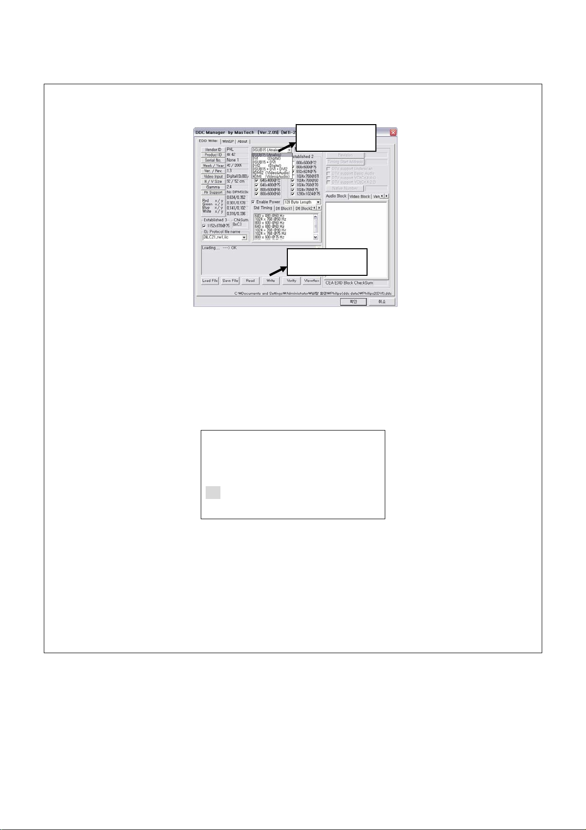
8) RGB Input(DDC DATA WRITE is optional per Buyer)
(1) Please connect the Parallel Port of DDC WRITER and the Parallel Port of PC to Cable.
(2) Please connect the ANALOG Port of DDC WRITER and the RGB Port of MAIN BOARD
to RGB Cable.
(3) Please send for RGB DDC FILE by pushing LOAD FILE after excelling the
DDC WRITE PROGRAM of PC.
DDC DATA File Load
Page 81

(4) Write Please choose Write Port(DSUB 15(Analog))
81/185
(5) Please change DDC DATA to Write format by pushing "Write" button.
WRITE PORT
White Button
(6) Please check DDC DATA by reading.
(7) Connect the out-coming of RGB Video signal to RGB input as 15 Pin D-Sub
(8) Connect the out-coming of RGB Audio signal to RGB Audio input as RCA Audio Cable
(9) Please power on by pushing front KEY or “POWER” of REMOCON
(10) Please select “RGB”terminal by using “-VOL+”,“-CH+”key after Input key of REMOCON
INPUT
SCART 1
.
RGB
(11) Please check that RGB Video signal is appearing in screen well after switching to
RGB Mode (Check the signal of DVI/RGB Mode Table)
(12) Please connect the RGB PORT of PC and the RGB PORT of MAIN BOARD to
15Pin D-SUB CABLE.
(13) Please check that the function of frame lock is normal by using the SCROLL KEY in KEY
BOARD and by controlling moving speed after excelling BLIT program of PC.
(The range of Frequency o Frame lock is 57Hz < Vsync < 61Hz)
* Frame lock working condition : Screen should not disappear when the screen be movable.
(14) Please check the Sound is good by pushing CONTROL KEY or “-VOL+”KEY of REMOCON
Page 82

Mode Resolution
82/185
640 x 350 31.460 70.000 25.170
640 x 400 37.861 85.000 31.500
720 x 400 31.469 70.000 28.320
Horizontal Frequency
(kHz)
Vertical Frequency
(Hz)
Pixel Clock Frequency
(MHz)
VGA
SVGA
XGA
31.460 50.000 25.170
31.500 60.000 25.175
640 x 480
37.700 72.000 31.500
37.500 75.000 31.500
43.300 85.000 36.000
35.100 56.000 36.000
37.900 60.000 40.000
800 x 600
48.100 72.000 50.000
46.900 75.000 49.500
53.700 85.000 56.250
832 x 624 49.720 75.000 57.280
48.400 60.000 65.000
56.500 70.000 75.000
1024 x 768
60.000 75.000 78.750
64.000 80.000 85.500
68.300 85.000 94.500
1152 x 870 68.680 75.000 100.000
SXGA 1280 x 1024 64.000 60.000 108.000
< DVI/RGB Mode Table >
Page 83

Mode Resolution
83/185
Horizontal Frequency
(kHz)
SDTV 480p 720 x 480 31.470 59.940 27.000
SDTV 576p 720 x 576 31.250 50.000 27.000
45.000 60.000 74.250
Vertical Frequency
(Hz)
Pixel Clock Frequency
(MHz)
HDTV 720p 1280 x 720
HDTV 1080i 1920 x 1080
44.960 59.940 74.180
37.500 50.000 74.250
33.750 30.000 74.250
33.720 29.970 74.180
31.250 25.000 74.250
28.125 25.000 74.250
< DVI/RGB Mode Table >
9) DVI Input
(1) Please connect the Parallel Port of DDC WRITER and the Parallel Port of PC to Cable.
(2) Please connect the DVI Port1 of DDC WRITER and the DVI Port of MAIN BOARD to DVI Cable.
(3) Please send for DVI DDC FILE by pushing LOAD FILE after excelling
the DDC WRITE PROGRAM of PC.
DDC DATA File Load
Page 84
(4) Please choose Write Port(DVI(Digital)) or DVI2(Digital))
84/185
(5) Please change DDC DATA to Write format by pushing "Write" button.
WRITE PORT
White Button
(6) Please check DDC DATA by reading.
(7) Connect ASTRO VG-848H of DVI output to DVI Video input
(8) Connect Audio out- coming of ASTRO VG-848H of DVI to DVI audio input
(9) Please power on PDP TV by pushing front key or “POWER” KEY of REMOCON
(10)Please select DVI Input by using “-VOL+”, “-CH+”key after pushing front KEY or
INPUT of REMOCON
INPUT
.
RGB
DVI
(11) Check DVI video signal is appearing well in screen after moving to DVI Input
(Check the signal of DVI/RGB Mode Table)
Page 85

85/185
(12) Please connect the DVI PORT of PC and the DVI PORT of MAIN BOARD to DVI CABLE.
(13) Please check that the function of frame lock is normal by using the SCROLL KEY in KEY
BOARD and by controlling moving speed after excelling BLIT program of PC.
(The range of Frequency o Frame lock is 57Hz < Vsync < 61Hz)
* Frame lock working condition : Screen should not disappear when the screen be movable.
(14) Check the sound is good after pushing the front key or “-VOL+”KEY of REMOCON
(15) Please connect the Serial Port of PC and the RS232C Port of Main Board to 9 Pin D-SUB
Cable
(16) Please execute the PWKeyLoader program
(17) Please click Setup tap and check the configuration of PWKeyLoader
(18) Please click Load. Then the HDCP key would be written
(19) Please connect the DVI output(with HDCP) of DVD Player and DVI input of Main Board
to DVI Cable
(20) Please check that video signal of HDCP is appearing rightly in screen
(21) Please check that Sound is good by pushing [-VOL+]key of front or remote control
Page 86

86/185
10)RS232C Control TEST
(1) Please connect the Serial Port of PC and the RS232C Port of Main Board
to 9 Pin D-SUB Cable
(2) Please execute the Docklight.exe
(3) Please choose Hardware Protocol as below.
- Baud rate : 19,200 bps
- Data bits : 8 bit
- Parity bits : NONE
- Stop bits : 1 bit
- Parity Error Character : Don’t care
Page 87

87/185
(4) Please check that RS232C CONTROL works well by putting the HEX MODE in program of Serial
Test through referring to Serial Control Protocols Manual.
ex) MUTE ON/OFF TEST (PDP ID : 01)
Mute : m (0x6d)
▶ To Control Mute On/Off
(1) Transmission
[0x57][m][ ][Display ID][ ][Data][CR][LF]
Data = 0(00h) : Off -----Æ57 6D 20 01 20 00 0D 0A
Data = 1(01h) : On -----Æ57 6D 20 01 20 01 0D 0A
(2) OK Ack
[0x06]
(3) Error Ack
[0x15]
▶ Read Mute Status
(1) Transmission
[0x57][m][ ][PDP ID][ ][0xFF][CR] -----Æ57 6D 20 01 20 FF 0D 0A
(2) OK Ack
[Data]
Data = 0(00h) : Off Status
Data = 1(01h) : On Status
(3) Error Ack
[0x15]
(5) Please check Command for [Operation Time] and [Reversal Image]
(Working at only RS232C CONTROL mode)
- [Operation Time] : Check operation time of PDP
- [Reversal Image] – ON : Check image is reversed
- OFF : Check image is defaulted
Page 88

14) Image Menu
88/185
(1) Please enter into Image MENU by pushing front key or MENU of REMOCON
Image
Brightness
Contrast
Sharpness
Color
Tint
Image Preset
(2) Checking that adjustment can be possible for whatever user want to adjust by pushing
front key or “-CH+”,“-VOL+”KEY of REMOCON
- Brightness : Resolution
- Contrast : Contrast
- Sharpness : Clearance
- Color : the tone of color
- Tint : the depth of color
- Image Preset: Image Mode first default
15) Screen
(1) enter into Screen MENU by pushing front key or MENU of REMOCON
(2) Please check following function can be working after selecting what function you want by
Pushing front KEY or “- VOL +”,“- CH +”key of REMOCON
Screen
Size
Freeze
Sticking Minimum
- Size : AUTO,FILL ALL, FILL ASPECT, ZOOM, ANAMORPHIC, WIDE,
- Freeze: Screen still
- Sticking Minimum : Panel Burn-in Protection
(When it is on the working Sticking Minimum function prevents Panel Burn-in
by moving screen as the left, the right or Up and down in a interval.)
Page 89

16) Setup Menu
89/185
(1) Please enter into Image MENU by pushing front key or MENU of REMOCON
(2) Check that adjustment can be possible for whatever user want to adjust by pushing
Setup
Language
Sleep Timer
OSD Settings
Transparency
Timeout
Color Temp
[-CH+] and [-VOL+]key
- Language : Each country language (This is optional by buyer)
- Sleep Timer : Reservation of sleep time
- OSD Settings
* Transparency : OSD the degree of clearness adjustment
* Timeout : OSD Time adjustment
- Color Temp : Choice color temperature(WARM/NORMAL/COOL)
17) Sound Menu
(1) Please check the volume of sound is adjustable by pushing front key or “-VOL+”KEY
of REMOCON
(2) Please enter into Sound MENU by pushing front KEY or MENU KEY of REMOCON
Sound
Volume
Treble
Bass
Balance
Mute
Audio Preset
(3) Checking that adjustment can be possible for whatever user want to adjust by pushing
Page 90

- Volume :
90/185
- Treble : High sound of Volume
- Bass : Low sound of Volume
- Balance : Sound balance
- Mute : Quiet
- Audio Preset: returning to Audio first Mode
18) Remote controller
Function Key Test
(1) Checking following details by pushing function key of REMOCON
- Mute(Quietly) : Once pushed at one time sound is dead. Once pushed again return to
the originated mode.
- Input : It help you see the input mode
- Auto(Auto setting) : It can help H.V position/Phase/Frequency searching automatically
in RGB Input
- I.SIZE(Screen size) : It can help screen size change like AUTO,FILL ALL, FILL ASPECT,
ZOOM, ANAMORPHIC, WIDE
- FREEZE(Screen freeze) : Once a time screen is frozen and Once pushed again it
return to default
- Recall(Input expression) : It help viewing in present input signal
- Sleep(sleep timer) : It can reserve the sleeper time whenever you push button
( OFF -> 30Minute -> 60Minute -> 90 Minute -> 120 Minute -> 150 Minute -> 180 Minute)
Page 91

91/185
- Split Screen : Picture is changed like below when user push Split key of Remocon
Main
PBP
PIP
-
< Normal -> PIP -> PBP >
- Locate(Screen Position) : Please move PIP Position from PIP Mode
- SIZE : PIP SCREEN Size is changing in PIP Mode
- SWAP(Swap) : This function has main screen switch off sub screen
- A.SWAP(Audio Swap) : This function has sound of main screen switch off sub screen
- S.SELECT : This function help selecting the each screen from Split Screen
Page 92

92/185
7.4 Out Going Specification
1) Menu Mode설정.
(1) Scart, Video, S-Video, Component Input
NO. Menu Function Default REMARK
1 Image Menu Brightness
Contrast
Sharpness
Color
Tint
Image Preset
2 Screen Menu Size
Freeze
Sticking Minimum
3 Setup Menu Language
Sleep Timer
OSD Settings
Transparency
Timeout
Color Temp
4 Audio Menu Volume
Treble
050
050
002
050
050
[-VOL+]to Preset Image
AUTO
OFF
OFF
Option by buyer
000
000
020
NORMAL
30
050
Bass
Balance
Mute
050
050
OFF
Audio Preset
< Table 1 >
※ Image, Screen, Setup, Audio Menu is the same as < Table 1>
Page 93

(2) RGB Input
93/185
NO. Menu Function Default REMARK
1 Image Menu Brightness
Contrast
Phase
Frequency
Sharpness
Image Preset
2 Screen Menu Size
H Position
V Position
Auto
Freeze
Sticking Minimum
3 Setup Menu Language
Sleep Timer
OSD Settings
Transparency
Timeout
050
050
002
AUTO
OFF
ON
Option by buyer
000
000
020
4 Audio Menu Volume
Color Temp
Treble
Bass
Balance
Mute
Audio Preset
< Table 2 >
NORMAL
30
050
050
050
OFF
Page 94

(3) DVI Input
94/185
NO. Menu Function Default REMARK
1 Image Brightness
Contrast
Sharpness
Image Preset
2 Screen Size
Freeze
Sticking Minimum
3 Setup Language
Sleep Timer
OSD Settings
Transparency
Timeout
Color Temp
4 Audio Volume
Treble
Bass
Balance
050
050
002
AUTO
OFF
ON
Option by buyer
000
000
020
NORMAL
30
050
050
050
Mute
OFF
Audio Preset
< Table 3 >
Page 95

Woosung Nextier Corp.
95/185
WOOSUNGNEXTIER CORP. EI NO.
USER FOR DISTRIBUTION DATE 07 / 22 / 2005
REVISION DATE DRAFTER REVISION
0 Initial
1
(1) Connect PC and PDP with RS-232C Cable (1:1 Serial cable).
(2) Remove AC Power Cord from PDP for Power off.
(2) Run "C:\......\FlashUpgrader.exe".
(3) Click "Flash" button.
07/22/2005
SUBJECT : Firmware Upgrade Manual
ENGINEERING INSTRUCTION
J.U-Lee 1.0
PAGE
NO:
1/1 Page
(4) Connect AC Power Cord of PDP.
(5) Right after connecting AC Power Cord, automatically up-grading.
(6) After finishing Up-grade, click " Close " button to end program.
(7) Remove RS-232C Cable ( 1:1 Serial Cable).
(8) Remove and reconnect AC Power Cord of PDP.
(9) Turn on PDP and Check the Panel Selection.
(10) If Panel Selection not corrected, Check whether appropriate panel is selected or not in
OSD Menu opened in a screen after Power On.
(12) Panel Selection can be changed by pushing down [VOL+], [CH-] and [CH+] button at the same time
as like below.
42” SD(Default) Æ 42” HD Æ 50” HD Æ LCD
(13) First Power Off and then Power On by Pushing down [Power] button if OSD Menu is stationed
in the middle of screen
(14) Check whether appropriate panel is selected or not in OSD Menu opened in a screen after Power On.
-The End-
- 1 -
Page 96
96/185
Serial Control Protocols
● How to connect a external equipment
Connect COM Port (9Pin D-Sub Port) of PC and RS-232C of PDP with
RS-232C Cable(1:1 Serial cable)
● Hardware Protocol
Baud rate : 19,200 bps
Data bits : 8 bit
2005,11,22 Ver.03
Parity bits : NONE
Stop bits : 1 bit
Handshake : NONE
● Transmission Formats
This is the format that the computer will send to the display to execute commands (such as Mute on,
Mute off, etc.). The format for this command transmission is as follows:
[Manufacturer ID ][Command][ ][PDP ID][ ][Data][CR]
Name Description ACSII code
Manufacturer ID The ID of the Manufacturer 0x57
Command The command to control the PDP
[ ] Space 0x20
PDP ID The ID of the PDP, from [001~254] 0x01~ 0xFE
[ ] Space 0x20
Data The data to be transmitted with the command
CR Carriage Return 0x0D
Page 97

97/185
● OK Acknowledgement
The acknowledgement will be sent by the display to the computer to verify that the command has been
successfully received and executed. This format for this acknowledgement is as follows:
[0x06]
● Error Acknowledgement
The Error Values will be sent by the display to the computer to verify that the command has been
successfully received and executed. This format for this Error Values is as follows:
[0x15]
● ASCII code
(American Standard Code for Information Interchange)
0 1 2 3 4 5 6 7 8 9 A B C D E F
*
0
NUL SOH STX ETX EOT ENQ ACK BEL BS TAB LF VT FF CR SO SI
1
DLE DC1 DC2 DC3 DC4 NAK SYN ETB CAN EM SUB ESC FS GS RS US
2
3
4
5
6
7
! " # $ % & ' ( ) * + , - . /
0 1 2 3 4 5 6 7 8 9 : ; < = > ?
@ A B C D E F G H I J K L M N O
P Q R S T U V W X Y Z [ \ ] ^ _
` a b c d e f g h i j k l m n o
p q r s t u v w x y z { | } ~
Example 1: ‘A’ character = 4th row, 1st column => Hex : 0x41 , Decimal : 65
Page 98

98/185
● HOW to Choose PDP ID number.
The adjustment range of Set ID is 001 ~ 255.
▶ To Choose PDP ID
(1) Transmission
[0x57][?][ ][0x00][ ][Data][CR]
Data = 001(01h)
number
.
.
Data = 128(80h)
.
.
Data = 254(FEh)
(2) OK Ack
[0x06]
(3) Error Ack
[0x15]
▶ Read PDP ID
(1) Transmission
[0x57][?][ ][0x00][ ][0xFF][CR]
(2) OK Ack
[Data]
Data = 001(01h)
number
.
.
Data = 128(80h)
.
.
Data = 254(FEh)
(3) Error Ack
[0x15]
Page 99

99/185
● Command List
Name Command Data(HEX) Name Command Data(HEX)
1. Mute m (0x6d) 00h ~ 01h 2. Power p (0x70) 00h ~ 01h
3. Remote Control Lock r (0x72) 00h ~ 01h 4. Input (Main) i (0x69) 01h ~ 0Eh
5. Keypad Lock k (0x6b) 00h ~ 01h
1. Mute : m (0x6d)
▶ To Control Mute On/Off
(1) Transmission
[0x57][m][ ][PDP ID][ ][Data][CR]
Data = 0(00h) : Off
Data = 1(01h) : On
(2) OK Ack
[0x06]
(3) Error Ack
[0x15]
▶ Read Mute Status
(1) Transmission
[0x57][m][ ][PDP ID][ ][0xFF][CR]
(2) OK Ack
[Data]
Data = 0(00h) : Off Status
Data = 1(01h) : On Status
(3) Error Ack
[0x15]
3. Remote Control Lock : r (0x72)
▶ To Control Remote Control Lock On/Off
(1) Transmission
[0x57][r][ ][PDP ID][ ][Data][CR]
Data = 0(00h) : Off
Data = 1(01h) : On
(2) OK Ack
[0x06]
(3) Error Ack
[0x15]
▶ Read Remote Control Lock Status
(1) Transmission
[0x57][r][ ][PDP ID][ ][0xFF][CR]
(2) OK Ack
[Data]
Data = 0(00h) : Off Status
Data = 1(01h) : On Status
(3) Error Ack
[0x15]
2. Power : p (0x70)
▶ To Control Power On/Off of the PDP TV
(1) Transmission
[0x57][p][ ][PDP ID][ ][Data][CR]
Data = 0(00h) : Off
Data = 1(01h) : On (PDP ID=[0x00] Fix)
(2) OK Ack
[0x06]:Off , [0xBE..,0xBF..,0xEF..]:On
(3) Error Ack
[0x15]:Off , [X]:On
▶ Read Power Status
(1) Transmission
[0x57][p][ ][PDP ID][ ][0xFF][CR]
(2) OK Ack
[Data]
Data = X(Don’t care) : Off Status
Data = 1(01h) : On Status
(3) Error Ack
[0x15]
4. Input(Main) : i (0x69)
▶ To select Input(Main) of the PDP TV
(1) Transmission
[0x57][i][ ][PDP ID][ ][Data][CR]
Data = 08(08h) : TV (Option)
Data = 11(0Bh) : SCART 1 or VIDEO 1
Data = 12(0Ch) : SCART 2 or VIDEO 2
Data = 01(01h) : VIDEO
Data = 02(02h) : S-VIDEO
Data = 07(07h) : COMPONENT
Data = 14(0Eh) : RGB
Data = 05(05h) : DVI
Data = 03(03h) : HDMI 1 (Option)
Data = 04(04h) : HDMI 2 (Option)
(2) OK Ack
[0x06]
(3) Error Ack
[0x15]
▶ Read Input(Main) Status
(1) Transmission
[0x57][i][ ][PDP ID][ ][0xFF][CR]
(2) OK Ack
[Data]
Data = 08(08h) : TV (Option)
Data = 11(0Bh) : SCART 1 or VIDEO 1
Data = 12(0Ch) : SCART 2 or VIDEO 2
Data = 01(01h) : VIDEO
Data = 02(02h) : S-VIDEO
Data = 07(07h) : COMPONENT
Data = 14(0Eh) : RGB
Data = 05(05h) : DVI
Data = 03(03h) : HDMI 1 (Option)
Data = 04(04h) : HDMI 2 (Option)
(3) Error Ack
[0x15]
Page 100

100/185
5. Keypad Lock : k (0x6b)
▶ To Control Keypad Lock On/Off
(1) Transmission
[0x57][k][ ][PDP ID][ ][Data][CR]
Data = 0(00h) : Off
Data = 1(01h) : On
(2) OK Ack
[0x06]
(3) Error Ack
[0x15]
▶ Read Keypad Lock Status
(1) Transmission
[0x57][k][ ][PDP ID][ ][0xFF][CR]
(2) OK Ack
[Data]
Data = 0(00h) : Off Status
Data = 1(01h) : On Status
(3) Error Ack
[0x15]
 Loading...