

Page 1

Philips
Business
Solutions
G
I
S
E
User Manual
Benützersanleitung
Philips
Business
Solutions
G
I
S
E
TYPE NR. BDS4221
42” Plasma Monitor
Page 2

Important Safety Instructions
WARNING
RISK OF ELECTRIC SHOCK
DO NOT OPEN
WARNING: To reduce the risk of electric shock, do not remove the front or back covers.
No user-serviceable parts inside. Refer servicing to qualified service personnel only.
The lightning flash with arrow-head
within a triangle is intended to inform
the user that parts inside the product
are a risk of electric shock.
The exclamation point within a triangle
is intended to tell the user that important
operating and servicing instructions are
explained.
Special Notices
! Certain programs may be copyrighted and any unauthorized recording in whole or in part may be in violation
of copyright laws in the U.S. and Canada.
! FCC/CSA regulations state that any unauthorized modifications to this display may void user authority to
operate it.
Warnings & Precautions
! To prevent damage which may result in fire or shock hazard, do not expose this product to rain or moisture.
! To prevent electric shock, do not remove cover. No user serviceable parts are inside. Refer servicing to
qualified service personnel only.
! Keep display away from excessive dust, high temperature, moisture or direct sunlight.
! Use in a well-ventilated area and do not cover ventilation openings.
! Unauthorized modifications to this equipment or usage of an unshielded connecting cable may cause
excessive interference.
! When the display is not in use, disconnect it from the electric outlet.
! If the picture displayed is in any way abnormal, turn off the unit and disconnect it from the electric outlet.
Verify your signal wire connections and reconnect the display to the electric outlet.
! Do not place this product on an unstable cart, stand or table. The product may fall, causing serious
damage.
! Do not place the unit on a bed, sofa, rug, or other similar surfaces.
! Never place the unit near or over a radiator or heat source.
! Do not install unit in an enclosed area unless proper ventilation is provided.
! The unit should be operated from the type of power source indicated on the label. If the type of available
power is unknown, consult your dealer or local power company.
! The unit is equipped with a 3-pin grounded plug. The plug will only fit into a grounded power outlet. This is a
safety feature. If you are unable to insert the plug into the outlet, contact your electrician. Do not alter this
plug as this will defeat the safety feature.
! Do not rest objects on the power cord & avoid placing power cord near high traffic areas.
! Do not overload wall outlets and extension cords as this can result in a risk of fire or electric shock.
! Unplug the display from the electric outlet and disconnect the antenna/cable TV system during a lightning
storm or when left unused for long periods of time. This will prevent damage to the display caused by
lightning and power-line surges.
! Avoid overhead power lines. An outdoor antenna system should not be placed in the vicinity of overhead
power lines, electric lights, or power circuits. When installing an outdoor antenna, be careful to not touch
any power lines or circuits as contact with these lines can be fatal.
! Do not insert any foreign objects through the ventilation openings to the display. It may touch dangerous
voltage points or damage parts.
2
Page 3

Important Safety Instructions
! If an outdoor antenna or cable system is connected to the display, be sure the antenna or cable system is
grounded to provide some protection against voltage surges and static charge buildups. Section 810 of the
National Electrical Code, ANSI/NFPA No.70-1984, provides information about proper grounding of the mast
and supporting structure, grounding of the lead-in wire to an antenna discharge unit, size of grounding
conductors, location of antenna discharge unit, connection to grounding electrodes, and requirements for the
grounding electrode.
! If this display is equipped with separate speakers, please remove the speakers prior to moving the display.
Moving the display with the speakers attached may cause damage or injury.
! Disconnect the unit from the main supply and refer servicing to qualified service personnel under the follow-
ing conditions:
- Power cord or plug is damaged or frayed.
- Liquid has been spilled into the product and/or the unit has been exposed to water or moisture.
- Unit does not operate normally when the operating instructions are not followed. Adjust only those
controls that are covered by the operating instructions, improper adjustment of other controls may result
in damage which often requires extensive work by a qualified technician to restore the unit to normal
operation.
- Unit has been dropped or the cabinet has been damaged.
- Unit exhibits a distinct change in performance, indicating a need for service.
Cleaning & Maintenance
! Disconnect from the electric outlet before cleaning. Do not use liquid or aerosol cleaners. Use only a slightly
damp cloth for cleaning.
Special Warranty Information
Cell Defects
! Although the display panels are produced with more than 99% percent active cells, there may be some cells
that do not produce light or remain lit. This is considered normal and not a manufacturer defect.
3
Page 4

Regulatory Notice
FCC Statement
The Federal Communications Commission Radio Frequency Interference Statement includes the following
warning:
This equipment has been tested and found to comply with the limits for a Class B digital device, pursuant to Part
15 of the FCC Rules. These limits are designed to provide reasonable protection against harmful interference in
a residential installation. This equipment generates, uses, and can radiate radio frequency energy and, if not
installed and used in accordance with the instructions, may cause harmful interference to radio
communications. However, there is no guarantee that interference will not occur in a particular installation.
If this equipment does cause harmful interference to radio or television receptions, which can be determined by
turning the equipment off and on, the user is encouraged to try to correct the interference by one or more of the
following measures:
- Reorient or relocate the receiving antenna.
- Increase the separation between the equipment and receiver.
- Connect the equipment into an outlet on a circuit different from that to which the receiver is connected.
- Consult the dealer or an experienced radio/TV technician for help.
Warning
User must use shielded signal interface cables to maintain FCC compliance for the product. Provided with this
display is a detachable power supply cord with IEC320 style terminations. It may be suitable for connection to
any UL Listed personal computer with similar configuration. Before making the connection, make sure the
voltage rating of the computer convenience outlet is the same as the monitor and that the ampere rating
of the computer convenience outlet is equal to or exceeds the monitor voltage rating. For 120 Volt applications,
use only UL Listed detachable power cord with NEMA configuration 5-15P type (parallel blades) plug cap. For
240 Volt applications use only UL Listed Detachable power supply cord with NEMA configuration 6015P type
(tandem blades) plug cap.
IC Compliance Notice
This Class B digital apparatus meets all requirements of the Canadian Interference-Causing Equipment Regulations of ICES-003.
Cet appareil Numerique de classe B respecte toutes les exigences du Reglemont NMB-03 sur les equipements
produisant des interferences au Canada.
Notice de Conformit IC
Cet appareil numerique de classe B respecte toutes les exigences du Reglement ICES-003 sur les equipements
produisant des interferences au Canada.
4
Page 5

Table of Contents
Important Safety Instructions ................................................................................................................... 2
Special Notices ................................................................................................................................ 2
Warnings & Precautions ................................................................................................................... 2
Cleaning & Maintenance ................................................................................................................... 3
Special Warranty Info ....................................................................................................................... 3
Regulatory Notice .................................................................................................................................... 4
Getting to Know Your Display .................................................................................................................. 7
Package Contents ............................................................................................................................ 8
Front Panel Controls ......................................................................................................................... 9
Rear Panel ........................................................................................................................................ 10
Rear Panel Connections ................................................................................................................... 10
Remote Control ................................................................................................................................. 11
Display Connections ............................................................................................................................... 13
Connecting TV or CATV .................................................................................................................... 14
Connecting a VCR ............................................................................................................................ 14
Connecting a DVD ............................................................................................................................. 15
External Audio Connections .............................................................................................................. 16
Connecting a PC .............................................................................................................................. 17
Basic Operations ..................................................................................................................................... 21
Powering On/Off ................................................................................................................................22
Changing Inputs ................................................................................................................................22
Volume Adjustment ........................................................................................................................... 23
On-Screen Display Menu .................................................................................................................. 24
On-Screen Status Display................................................................................................................. 24
Understanding Widescreen Modes .................................................................................................... 25
Picture Controls ...................................................................................................................................... 27
Adjusting Picture Settings ................................................................................................................ 28
Picture-in-Picture / Side-by-Side Picture ........................................................................................... 30
Selecting Color Temperature ............................................................................................................. 33
Fine Tuning RGB Mode ..................................................................................................................... 33
Sound Controls ....................................................................................................................................... 35
Adjusting Sound Settings ................................................................................................................. 36
Built-in Amplification (Speaker) .......................................................................................................... 38
Fixed / Variable Audio Output ........................................................................................................... 38
Advanced Functions ................................................................................................................................39
OSD Menu Language ........................................................................................................................ 40
Power Save Mode ............................................................................................................................. 41
Information Display............................................................................................................................ 42
Using the Teletext ............................................................................................................................. 43
TV Functions........................................................................................................................................... 45
Initial Set Up ..................................................................................................................................... 46
Channel Manual Search .................................................................................................................... 47
Channel Edit ..................................................................................................................................... 48
On-Screen Status Display (TV Mode) ............................................................................................... 49
Changing Channels ........................................................................................................................... 49
Sound Type ...................................................................................................................................... 50
Appendix ................................................................................................................................................. 51
Troubleshooting ................................................................................................................................52
Wall Mount Instructions .................................................................................................................... 53
Specifications ................................................................................................................................... 55
5
Page 6

6
Page 7

Flat Panel Monitor
Getting to Know
Your Display
7
Page 8

Getting to Know Your Display
Package Contents
Flat Panel Display Remote Control
User Manual AC Power CordVGA Cable
Batteries
8
Page 9

Front Panel Controls
Getting to Know Your Display
Status LED
Not Illuminated - No AC Power detected
If the main power switch (rear of panel) is turned off,
this LED will not illuminate.
Orange - Standby (Power OFF) with AC power
detected
The LED will illuminate in orange color if the monitor
is shut-off but the main power cord is plugged into
the back of the unit.
Solid Green - Power ON
Power (Standby) Button
Turns power on/off from standby mode. There is a
wait period between on/off cycles.
Volume Adjustment Buttons
Use these buttons to adjust volume up and down.
These keys also serve as navigation and adjustment keys when On Screen Display menu is
engaged.
Select Buttons
Use these buttons to navigate through the the On
Screen Display menu.
Menu Button
Use this button to engage the On Screen Display
menu.
Input Button
Use this button to switch between available inputs.
9
Page 10

Getting to Know Your Display
Rear Panel
Video Connectors
RGB/Computer Related Connector
Rear Panel Connections
S-Video Inputs
Connect S-Video signals from
external sources such VCRs or DVD players.
Component Video Inputs
Auto-detecting component video inputs (Y/Pb/Pr or
Y/Cb/Cr) for connecting to the component output
jacks of a DVD player or Set-Top Box.
Audio Output
Variable or fixed audio output jacks for connecting
to an external audio amplifier.
Antenna Jack
Connect to TV or CATV antenna.
10
RGB Input
Connect to RGB output of computer or Set-Top box.
RGB Output
Connect to another computer monitor for daisy
chaining applications.
RS-232 Connector
For factory use only
Digital DVI Input
Connects to the digital video signals
from a set top box or PC.
Page 11
Getting to Know Your Display
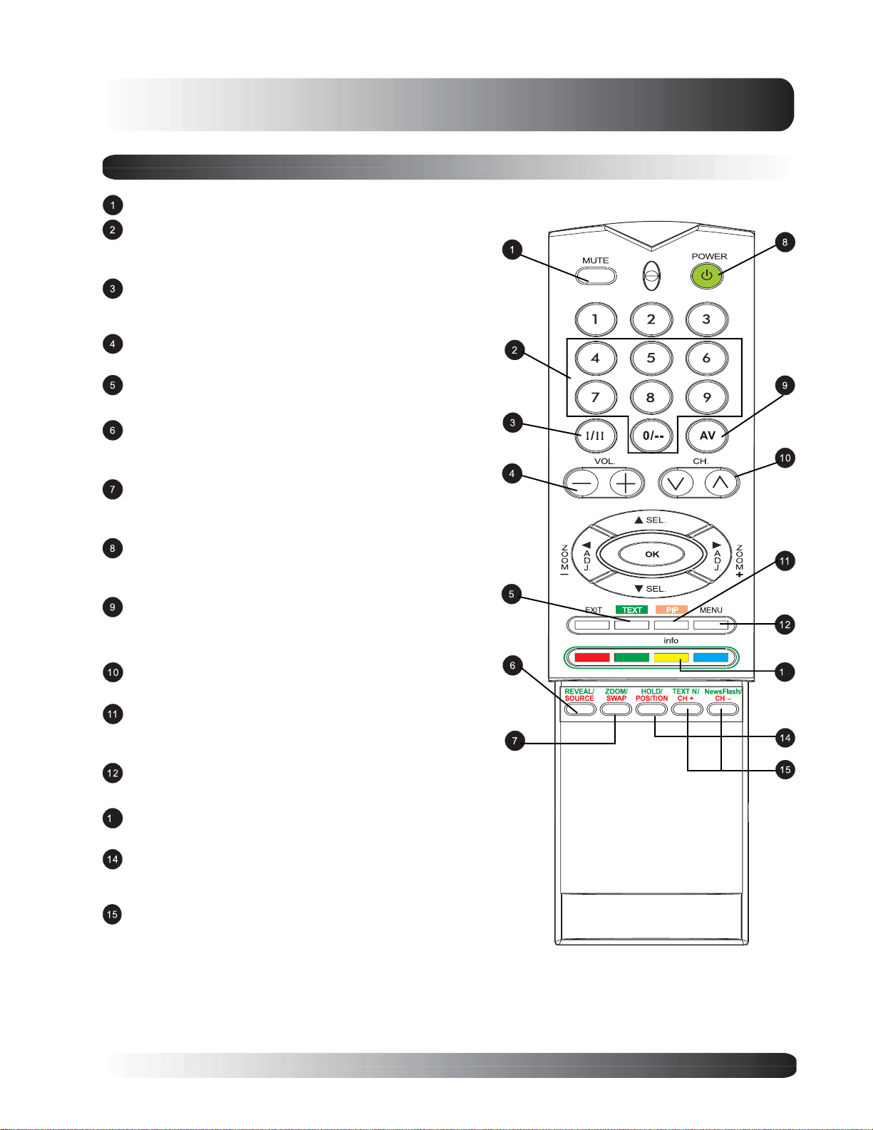
Remote Control
Sound Mute On/Off
Number Keypad
Use number keypad to select the TV channel you want to
watch.
Stereo and Dual
Engages Stereo reception for TV or Dual for second
language.
Volume +/-
Turns volume up or down
Teletext
Press TEXT key to go to TELETEXT mode.
PIP/POP Source
Changes the input source of the PIP or POP sub-window.
(See Page 31)
Swap
This key swaps the main and sub picture windows under
PIP or POP modes. (See Page 32)
Standby Power On/Off
Push this button to turn on the monitor from Standby
mode. Push it again to turn off to Standby mode.
Input Select
Press to select input signal modes sequentially. (See
Page 26)
Channel UP/DOWN
Change TV channels sequentially by pressing +/-.
PIP (Picture-in-Picture Button)
Turns on PIP (Picture-in-Picture) mode and POP (Side-by-
Side) picture mode.
Menu
Engages the OSD menu
3
Info
press to show the status of the monitor.
PIP Position
This key changes the PIP sub-window to 4 different corner
locations. (See Page 32)
Sub-Picture Channel UP/DOWN
3
11
Page 12

Getting to Know Your Display
12
Page 13

Flat Panel Monitor
Display
Connections
13
Page 14

Display Connections
Connecting TV or CATV
Connect the RF cable from the antenna or cable
socket to the RF connector labeled as ANT on
the back of the monitor.
Connecting a VCR
Using SCART (AV) socket input
Connect the SCART socket on the
videorecorder to the SCART socket on the rear
panel of the set.
Connect the videorecorder to the antenna wall
socket or cable box.
Using S-Video Input
Connect the S-Video (4-pin DIN) connector from
the VCR to the S-Video input on the back of
monitor.
Connect the red (R) and white (L) audio jacks
from the VCR to the (R) and (L) audio-in jacks
located next to the S-Video connector.
Using TV Input
Connect the antenna out socket on the
videorecorder to the corresponding socke
(ANT) on the rear panel of the set.
Connect the videorecorder to the antenna wall
socket or cable box.
14
Page 15

Connecting a DVD Player
Using SCART (AV) socket Input
Using SCART (AV) socket input
Connect the SCART socket on the DVD player
to the SCART socket on the rear panel of the
set.
Display Connections
Using component video input
Connect the green-colored (labeled as Y) jack
from the DVD to the green-colored jack of the
monitor.
Connect the red-colored (labed as Pr / Cr) jack
from the DVD to the red-colored Pr/Cr jack of the
monitor.
Connect the blue-colored (labed as Pb / Cb)
jack from the DVD to the blue-colored Pb/Cb
jack of the monitor.
Connect the red (R) and white (L) audio jacks
from the DVD to the R and L audio-in jacks
located next to the Pr/Cr connector.
15
Page 16

Display Connections
Connecting a DVD (con’t)
Using S-Video Input
Connect the S-Video (4-pin DIN) connector from
the DVD to the S-Video input on the back of
monitor.
Connect the red (R) and white (L) audio jacks
from the DVD to the (R) and (L) audio-in jacks
located next to the S-Video connector.
External Audio Connections
Connecting to an External Amplifiers
This monitor can be connected to an external
amplifier using the AUDIO OUT jacks located
on the back of the monitor.
Connect the red (R) and white (L) AUDIO OUT
jacks from right side of the connector panel to
the external amplifier.
Note:
! The AUDIO OUT RCA jacks can be set to
either Fixed or Variable audio output levels.
(See Page 38 for more information)
16
Page 17

Connecting external amplified speakers
Connect the red (R) and white (L) audio out
sockets located to the right of the connector
panel of the set respectively to the right and left
amplified speakers.
Connecting a PC
Using RGB or DVI Video Input
Display Connections
For most PCs, connect the 15-pin D-Sub RGB
connector from the back of the PC to the RGBIN Connector located on the back of the
monitor. If you have a PC that is equipped with
a DVI (Digital Visual Interface), you may
connect the PC DVI connector from the back of
the PC to the DVI-In Connector located on the
back of the monitor.
Connect the red (R) and white (L) audio jacks
from the PC to the R and L jacks located next
to the AUDIO OUTPUT. If you are using a DVI
interface, simply connect the (R) and (L) audio
jacks to the same jacks as RGB.
Note:
! A RGB loop-out labeled RGB Out will allow another RGB monitor to be connected. The RGB loop-out
will display the same signal as the RGB In signal source.
17
Page 18

Display Connections
Connecting a PC (con’t)
Setting Up Your Monitor Using Plug and Play
This monitor adheres to VESA Plug and Play standard to eliminate complicated and time consuming setup of
monitors. This monitor identifies itself to the computer and automatically sends the PC its Extended Display
Identification Data (EDID) using Display Data Channel (DDC) protocols.
How to Set up Your PC for Use with Monitor (Windows)
The display settings for a typical Windows-based computer are shown below; however, actual screens on your
computer will differ depending on the version of Windows and video card equipped with the computer. Even
though the actual screen may look different from example displayed below, basic set-up routine will apply in
most cases.
Go to Window’s CONTROL PANEL by clicking:
START, SETTINGS, CONTROL PANEL. The
CONTROL PANEL Window is displayed. Select
the DISPLAY icon from this window.
The DISPLAY PROPERTIES dialog box is
displayed. Select the SETTINGS tab to display
your computer’s video output settings.
Set the “Screen Resolution” settings to 640x480
PIXELS. For COLOR QUALITY, select 24 BIT
COLOR (might also be expressed as 16 million
colors).
If a vertical-frequency option exists, set the value to
60 or 60 Hz.
Click OK to complete the setting.
Note:
! Both screen position and size will vary, depending on the type of PC graphics card and its resolution
selected. To adjust position and size.
18
Page 19

Connecting a PC (con’t)
Supported Resolutions
This monitor supports the following resolutions
Mode Horizontal Vertical Format Refresh rate
1 31.469 59.940 640×480 (VGA) 60
2 37.861 72.809 640×480 (VGA) 72
3 37.500 75.000 640×480 (VGA) 75
4 43.269 85.008 640×480 (VGA) 85
5 35.156 56.250 800x600 (SVGA) 56
6 37.879 60.317 800x600 (SVGA) 60
7 48.077 72.188 800x600 (SVGA) 72
8 46.875 75.000 800x600 (SVGA) 75
9 53.674 85.061 800x600 (SVGA) 85
10 48.364 60.004 1024x768 (XGA) 60
11 56.476 70.069 1024x768 (XGA) 70
12 60.023 75.029 1024x768 (XGA) 75
13 68.677 84.997 1024x768 (XGA) 85
14 63.981 60.020 1280x1024 (SXGA) 60
15* 79.976 75.025 1280x1024 (SXGA) 75
16* 91.146 85.024 1280x1024 (SXGA) 85
18 31.469 70.087 720x400 (DOS) 70
19 31.469 50.030 640x480 (VGA) 50
20* 45.000 60.000 1280x720p (HDTV) 60
21* 33.750 60.000 1920x1080i (HDTV) 60
22 31.469 70.087 640x350 (VGA) 70
23 31.413 59.835 852x480 (WVGA) 60
24 35.000 66.667 640x480 (Apple) 67
25 49.725 74.550 832x624 (Apple) 75
26 68.681 75.062 1152x870 (Apple) 75
Display Connections
Notes:
Modes 15, 16 are not available with DVI input.
Modes 24, 25 and 26 are for use with Apple Macintosh computers.
19
Page 20

Display Connections
20
Page 21

Flat Panel Monitor
Basic
Operations
21
Page 22

Basic Operations
S-VIDEO
Powering On/Off
Using Front Panel or Remote Control
Make sure the monitor is plugged into the wall outlet and the main AC switch located on the rear of the monitor
is switched to ON position. If the power is plugged in and the AC switch is on, the STATUS LED will illuminate
in orange color.
Press the key on the panel or the remote
control.
The monitor will now turn on after a brief pause.
The STATUS LED will now turn green to
indicate power on status.
To turn power off, simply press the key on
the panel or the remote control once again.
Changing Inputs
Using Front Panel or Remote Control
Press the INPUT key on the panel or the
key on the remote control.
Pressing the INPUT key will cycle the monitor
through all available input signal sources in the
following order:
POWER (Toggle)
Input Select
(Toggle)
22
S-VIDEO
Page 23

Volume Adjustment
Using Front Panel or Remote Control
To turn up sound volume, press VOLUME + on
either the front panel of monitor or on the
remote control.
To turn down sound volume, press VOLUME on either the front panel of monitor or on the
remote control.
Note:
! If the monitor’s built-in speakers are turned
off, then volume controls will not affect
volume generated by the built-in speaker.
Basic Operations
VOLUME +/-
Using MUTE
If you would like to silence the volume on a
temporary basis, simply press the key to
silence the volume. When the monitors volume
is muted, the monitor will display MUTE on the
bottom left corner of the screen.
To disengage the mute mode, simply press the
key again or the volume buttons.
Note:
! If the monitor’s built-in speakers are turned
off, then volume controls will not affect
volume generated by the built-in speaker.
MUTE
23
Page 24

Basic Operations
On-Screen Display Menu
Accessing OSD Menu via Remote Control or Front Panel
The On-Screen Display (OSD) menu allows access to setup various parameters equipped with this display.
To access the OSD menu, press
on the front panel of monitor or press any one of
the four arrow keys located on the remote
control.
Navigation through the OSD Menu can be
accomplished using the arrow keys on the
remote control or using the front panel control
keys.
button
OSD Menu
Navigation
OSD Menu
Access
On-Screen Status Display
Displaying Status
The On-Screen Status Display shows detailed information regarding the operational status of the monitor. The
status display automatically appears whenever there is a change in the state of the monitor such as channel
change or input change. The status display will automatically disappear after a timeout period.
To manually show the Status Display, simply
press the key on the remote control.
AV Mode
PIP
24
AV CVBS Stereo 16:9
Component Mode
Y Cb Cr Stereo 16:9
RGB/DVI Mode
VGA M.21 Stereo 16:9
Input Source
Input Source
Input Source
Signal Format
Page 25

Basic Operations
Understanding Widescreen Modes
This monitor is capable of displaying a widescreen image on the native 16:9 aspect ratio screen. However, not
all available video content fits perfectly in a widescreen (16:9) format resulting in unused screen space. This
monitor is capable of displaying images in various formats that is suitable for various types of content depending
on its size.
For 4:3 (Square) Content
Content from traditional TV, VCR, and some DVD’s are formatted using a “square” 4:3 format. When
viewing content in this “Square” format the following viewing modes are suitable.
4:3 (NORMAL)
In 4:3 mode, the original 4:3 image is preserved but black bars are used to fill
the the extra space on the left and right.
16:9 (FULL)
The original 4:3 image is proportionally stretched to fill the entire screen. This
is the default setting from factory.
CINERAMA
The original 4:3 image is stretched only on the left and right sides to fill the
screen, leaving the center image unchanged.
For Widescreen Content
Depending on the content displayed on this 16:9 monitor, you may notice smaller black bars on top or
bottom of the screen. Use the following zoom modes to elimate black bars.
ZOOM
Zoom is set to stretch 2.35:1 content to full screen eliminating the black
bars.
ZOOM
Zoom is set to show the picture with subtitles.
25
Page 26

Basic Operations
Changing Aspect Ratios
Using Remote Control
All widescreen viewing modes are available by
pressing the key.
Note:
! Under RGB and DVI input modes, only 16:9
WIDE and 4:3 Normal modes are available.
! When displaying Y Pb Pr signals,
Cinerama mode is not available.
Zoom
Key
26
Page 27

Flat Panel Monitor
Picture Controls
27
Page 28

Picture Controls
Adjusting Picture Settings
.
Using OSD Menu
Various picture adjustments can be set using the Picture Adjustment OSD menu.
Press the on the front panel or remote
control. Use to select the PICTURE
option from the menu.
Various picture settings are available from the
PICTURE menu. Use to select the
option that you wish to adjust and press
key
Notes:
! H-Position, H-Size, V-Position, V-Size
adjustments are only available in RGB,
DVI, and Component input with Y Pb/Pr.
! When using Component input with Y Cb/Cr
signals, H-Size, H-Position, V-Position, VSize settings are not available.
Explanation of Various Picture Control Settings
Explanation of each available picture control settings are listed in the table below.
CONTRAST
Adjust Contrast to increase or decrease the level of white in the video picture. Increasing contrast will
make white areas of the video picture brighter. Contrast works in conjuction with Brightness.
28
Page 29

Picture Controls
BRIGHTNESS
Adjust brightness to enhance the level of dark aread in the video priture such as night scenes and
shadow scenes. Increasing brightness will make dark areas more visible.
COLOUR
Use color to adjust the color saturation of the video picture. Increasing color will make the color
more intense. Reducing color setting will make the color less intense.
TINT
Use tint to adjust the color of fleshtones. Increase in the right direction will shift the picture with
more green in appearance. Decreasing setting in left direction will shift the picture with more red in
appearance.
SHARPNESS
Use sharpness to adjust the amount of detail enhancement to the cideo picture. Increasing the
setting will enhance the edges of objucts in the video picture. Decreasing the setting will reduce
enhancement.
TONE
Select the color temperature for white balance. There are three settings to choose from : Cold,
Neutral, Warm.
AUTO FORMAT
Use to turn on the auto format of screen or turn off. System will determine the format according to
the signal when you turn on the auto format, otherwise, the screen will remain in 16:9.
V-SIZE
Use to change vertical size of the picture. Increase to enlarge the picture size in the vertical
direction. Decrease to reduce the picture size in the vertical direction.
V-POSITION
Use to change vertical position of the picture. Increase to shift the picture up. Decrease to shift the
picture down.
H-SIZE
Use to change horizontal size of the picture. Increase to enlarge the picture size in the horizontal
direction. Decrease to redice the picture size in the horizontal direction.
H-POSITION
Use to change horizontal position of the picture. Increase to shift the picture to the right. Decrease
to shift the picture to the left.
CLOCK PHASE
Use clock phase to fine-tune the monitor to perfectly synchronize to the video signal source under
RGB mode.
Notes:
! H-Position, H-Size and V-Position adjustments are only available in RGB, DVI, and Component input modes
higher than 480i.
! When using Component inputs with Y Cb/Cr signals, H-Size, H-Position, V-Size, V-Position settings are not
available.
29
Page 30

Picture Controls
Picture-in-Picture / Side-by-Side Picture
Turning On PIP/Side-by-Side Picture (POP)
PIP and POP modes allow users to view two video input sources simultaneously.
Press the key once on the remote control
to engage in Picture-in-Picture mode. Pressing
the key repeatedly will cycle thru the following
modes:
PIP Key
When engaged in PIP mode, a small window is
displayed in one of the four corners. The OSD
on the bottom left corner will denote the input
selected for main picture (large screen) and the
sub-picture (small screen) displayed.
Note:
! Once PIP is turned off, the next time you
return on PIP mode, the position of the subwindow will start at default position.
If switched to POP mode, the screen will be
split in half. The screen on the left side is the
main picture and the screen on the right is the
sub-picture. The OSD on the bottom left corner
will denote the input signal source for both the
main and sub-pictures.
There are two Side-by-Side picture modes
available in addition to the standard POP mode.
POP (4:3) mode will display both main and subpicture in a 4:3 aspect ratio within the POP
windows. POP (16:9) mode will display both
main and sub-picture in 16:9 aspect ratio within
the POP windows.
PIP Mode
S: AV
M: TV
POP Mode
S: AV
M: TV
POP 4:3 Mode
Main
Picture
Input Source for
Main Picture
Input Source for
Sub Picture
Sub
Picture
Main
Picture
Input Source for
Main Picture
Input Source for
Sub Picture
Sub
Picture
Main
Picture
Sub
Picture
30
POP 16:9 Mode
Main
Picture
Sub
Picture
Page 31

Picture Controls
S-VIDEO
Selecting Signal Source for Sub-Picture
Various signal sources can be displayed within the sub-window under PIP and Side-by-Side picture modes. To
select the input source for sub-window, please follow the steps below.
Once the PIP mode is turned on, you can
change the sub-picture input source by press-
ing the
Pressing the key repeatedly will cycle
through all available inputs for the sub-picture.
key.
Source
Select
S-VIDEO
Selecting Signal Source for Main Picture
Once the PIP mode is turned on, you can
change the main picture input source by
pressing the key.
Input select
31
Page 32

Picture Controls
Picture-in-Picture / Side-by-Side Picture (Con’t)
Main and Sub-Window Swap
You can swap the main picture and sub-picture.
Press the key once to swap. Press the
key once again to switch back.
Picture
Swap
Changing Location of PIP Image
There are four preset positions where the PIP sub-window can be positioned. Once the PIP mode is turned on,
you can switch the PIP sub-picture position to any one of the four corners of the screen.
Press the key to switch positions. Pressing the key repeatedly will cycle through all
four corners of the screen.
Sub-Picture Positions
Default
Position
Changing Channels in PIP Mode
When under PIP or POP modes, if TV mode is in main window, just use the method described below to change
TV channels.
To change main window’s TV channels, simply
press the key to change channels.
Main Window
Channel Up/Down
32
Page 33

Picture Controls
Selecting Color Temperature
This monitor is capable of applying various color temperatures (also known as White Balance) onto the video
signal for display.
Press the on the front panel or remote
control. Use to select the PICTURE
option from the menu.
Various settings are available from the PICTURE menu. Use to select the
TONE option from the menu.
Use to change the setting. Press EXIT to
close the OSD screen or press key
to keep adjusting.
Fine Tuning RGB Mode
Due to various PC video cards and set-top boxes with differing specifications, it is likely that the initial video
picture have subtle noise or imperfections. Please use the following procedures to adjust the picture quality
when using under RGB mode.
Press the on the front panel or remote
control. Use to select the PICTURE
option from the menu.
Use to select CLOCK PHASE option
from the menu.
Use to change the setting so that your
video picture is best fit within the display area of
the monitor. Press EXIT to close the OSD
screen or press to keep adjusting.
33
Page 34

Picture Controls
In certain special cases, users may desire to manually adjust V-Size. To do so, please use the following
procedures:
Due to various PC video cards and set-top boxes with differing specifications, it is likely that the initial picture
may not fit exactly to the size of the monitor. Please use the following procedures to adjust the picture size and
position.
Press the on the front panel or remote
control. Use
option from the menu.
Various settings are available from the PICTURE menu. Use to select V-Size,
V-Position, H-Size, or H-Position from the
menu.
Use to change the setting so that your
video picture is best fit within the display area of
the monitor.
Repeat procedure for V-Size, V-Position, H-Size,
and H-Position settings until video picture is
fully displayed within the monitor’s display area.
to select the PICTURE
34
Page 35

Flat Panel Monitor
Sound Controls
35
Page 36

Sound Controls
Adjusting Sound Settings
.
Using OSD Menu
Various sound adjustments can be set using the Sound Adjustment OSD menu.
Press the on the front panel or remote
control. Use to select the SOUND option
from the menu.
Various SOUND settings are available from the
SOUND menu. Use to select the
option that you wish to adjust.
Use to change the setting. After achiev-
ing desired setting, press EXIT key to close the
OSD screen or press key to keep
adjusting.
36
Page 37

Explanation of Various Sound Control Settings
Explanation of each available sound control settings is listed in the table below.
BASS
Adjusts the BASS level of the sound. For more bass response, increase the BASS level.
TREBLE
Adjusts the TREBLE level of the sound. For more vocal and high frequency response, increase the
TREBLE level.
BALANCE
Adjusts the BALANCE level between LEFT and RIGHT channels.
SPEAKER
Sets the speakers to ON to turn on the speakers or sets the speakers to OFF to turn off. This setting
will not affect AUDIO OUTPUT jacks.
Sound Controls
AUDIO OUTPUT
Sets the type of audio output sent from the audio output jacks located in the rear of monitor. When
set to VARIABLE, audio output is affected by the monitor’s internal volume controls . When set to
FIXED, the audio output bypasses the monitor’s internal audio control so that functions such as bass,
treble and volume controls have no effect.
37
Page 38

Sound Controls
Built-in Amplification (Speaker)
.
.
Turning On Built-in Amplification
This monitor is equipped with a built-in amplication for optional external speakers. You can switch the amplification ON or OFF using the OSD. Because these speakers are general purpose, you may consider switching
them OFF during hi-fidelity playback of movies or other content.
Press the on the front panel or remote
.
control. Use
.
from the menu.
Use to select the INTERN.SPEAKER
option.
Use to change the setting. To turn OFF,
select OFF position. After achieving desired
setting, press EXIT key to close the OSD
screen or press key to keep
adjusting.
to select the SOUND option
Fixed / Variable Audio Output
Setting Output Using OSD Menu
You can set the type of output this monitor outputs from its rear panel audio output jacks. By using OSD menu,
you can easily choose between variable or fixed audio outputs.
Press the on the front panel or remote
control. Use to select the SOUND option
from the menu.
Use to select the AUDIO OUTPUT
option.
Use to change the setting. When set to
VARIABLE, audio output is affected by the
monitor’s internal audio controls. When set to
FIXED, the audio output bypasses the monitor’s
internal audio controls. After achieving desired
setting, press EXIT key to close the OSD screen or
press key to keep adjusting.
38
Page 39

Flat Panel Monitor
Advanced Functions
39
Page 40

Advanced Functions
OSD Menu Language
.
Setting OSD Menu Language
This monitor has multiple OSD Menu languages built-in including: English, French, Spanish, Italian and German.
Press the on the front panel or remote
control. Use to select the OTHER option
from the menu.
Use to select the MENU LANGUAGE
option.
Use to select the desired OSD language.
Available settings are: ENGLISH, FRENCH,
SPANISH, ITALIAN, GERMAN. Press EXIT to
close the OSD screen or press key
to keep adjusting.
40
Page 41

Advanced Functions
Power Save Mode
j
Setting Power Save Mode Using OSD Menu
This monitor is equipped with a Power Save mode under RGB or DVI input modes. When there are no signals
detected by the monitor for 15 minutes, the monitor will automatically go into sleep mode until signal is restored.
Press the on the front panel or remote
control. Use
from the menu.
Use to select the POWER SAVE
option.
Use to turn on the power save function or
turn off. After achieving desired setting, please
press EXIT to close the OSD screen or press
key to keep adjusting.
to select the OTHER option
.
41
Page 42

Advanced Functions
Information Display
The information display sub-menu retains much useful information regarding the status of the monitor. Explanations for each type of information being displayed are listed below.
Accessing Information Display Menu
Press the on the front panel or remote
control. Use
from the menu.
Various information is displayed in the INFO
menu. To exit the INFO menu, press EXIT on
remote control.
to select the OTHER option
Explanation of Information
S/W Version
Shows the monitor’s firmware version number.
42
Page 43

Using the Teletext
The Teletext service is available in many countries under a variety of names (TOP Text, Fastext, FLOF test,
Videotext). It is provided as a free service by some television broadcasters. This service provides a real wealth
of information, available at any time, on weather, sporting results, news, games, etc. The information is presented in pages or organised in topics specified in colour on the screen and you can access this information by
simply pressing the buttons of the same colour on the remote control.
To access the Teletext, press the button on the remote control. Teletext opens on the index page(100).
To display another page, use the buttons to select the next and previous pages, or enter its number
using the numeric buttons.
The page/subpage number appears:
1. In green when the page has not been found yet.
2. In white when the page has been found.
A teletext page contains a header line with page and subpage number, and broadcaster information (date and
time, channel number, etc.).
When enter the main screen of Teletext(index page), there are some options with colour desplayed at the
bottom of the screen and gives direct access to the corresponding pages, just press the relevant buttons on
the remote control.
This unit also provides several Teletext functions:
Hold: freezes the current page, preventing update and subpage display. To select this function, press the
button on the remote control. To cancel, press the button again.
REVEAL: to reveal a hidden page information, just press the button to show the information again.
ZOOM: press the button once to zoom in on the top part of the screen, twice to zoom in on the bottom
part of the screen, and three times to return to normal display.
If you want to show PIP in Teletext, press the button on the remote control first to display PIP screen,
then press the button on the remote control
Newsflash
When access NewsFlash page, Teletext is automatically enabled and displays the new information. If you
want to hide the information screen, just press to conceal the screen, to show, just press again.
TEXT N
You can change the character of Teletext at any time, just press the button and there are 7 Texts can be
chose.
43
Page 44

Using the Teletext
Other useful functions in Teletext
Subtitles
Some channels provide subtitles for some of their programmes through Teletext. The numbers of
the relevant pages are specified on the Teletext index page.
To display the subtitles, enter the number of the relevant page. Once it is found, the subtitles
appear in the TV picture. The header disappear after a couple of seconds. To display them again,
press any button (except EXIT or the volume adjustment buttons) on the remote control.
To return to TV mode, press EXIT.
Alarm page
In some countries (Spain, Benelux, etc.), you can set a time to display certain Teletext pages (alarm
pages).
To do this, display the relevant alarm page and press the
Enter the time instead of the subpage number (e.g. 1435 for 14:35) and press exit. The page will
disappear and will appear again at the set time, as long as you do not change channels or switch off
the set beforehand.
and buttons to enter subpage mode.
Fasttext
If fasttext is available, you can easily access the topic and relevant pages you want by pressing the
red, green, yellow and blue buttons on the remote control.
In Teletext mode, volume controls remain available, but the relevant symbols are not shown on the
screen.
44
Page 45

Flat Panel Monitor
TV Functions
45
Page 46

TV FUNCTIONS
Initial Set Up
When you turn on the TV first time, the
language selection appears, choose one of
them then press key to confirm the
selection.
A list of countries appears, use
key to select the country you are in. If your
country is not in the list, select Other.
The monitor will now search all available
channels. It may take several minutes for the
search to complete. When the search is
complete, the screen will show how many
channels are found then change to the EDITOR
screen.
46
Page 47

TV Functions
Channel Manual Search
You may also make a manual search, in case, some channels are not stored during the initial set up, just key in
all required settings then system would strart searching.
Press the on the front panel or remote
control. Use to select the TV option from
the menu.
Various TV settings are available from the
SETUP menu. Use to select the
MANUAL SEARCH option. Press key to
confirm selection.
Select the “ Standard ” option and choose
signal system first then use to search the
frequency based on the current frequency
showed on the menu. Or you can just key in
the frequency with number key on the remote
control.
When a channel is searched, the “ Save on
CH “ option will be flashing with red color.
Press OK key to confirm the channel which
is searched.
47
Page 48

TV Functions
Channel Edit
Users can swap, delete the channel, even to change the name of channel in EDITOR menu.
Press the on the front panel or remote
control. Use
the menu.
Various TV settings are available from the
SETUP menu. Use to select the
EDITOR option. Press key to confirm
selection.
The EDITOR menu is now displayed. Use
keys to select SWAP, DELETE or
CHANGE CH NAME to do the revelant setting.
to select the TV option from
After adjusting, press OK key to confirm.
48
Page 49

TV Functions
On-Screen Status Display (TV Mode)
Displaying Status
The On-Screen Status Display shows detailed information regarding the operational status of the monitor under
TV mode. The status display automatically appears whenever there is a change in TV channels. The status
display will automatically disappear after a timeout period.
To manually show the Status Display, simply
press the key on the remote control.
.
TV Mode (Single Tuner)
CH 02
Antenna Type/Channel
Changing Channels
Using Remote Control or Front Panel
To change TV channels, users can use either the remote control or the front panel keys.
Switch input to TV. Press button on the
remote control to change channels. To use the
front panel, press SEL UP/DOWN keys to
adjust the TV channels when there is no OSD
on the screen.
CHANNEL
Up/Down
49
Page 50

TV Functions
SOUND TYPE
SOUND TYPE option sets audio reception settings for the TV tuner. This function is also accessible using the
remote control key. Pressing the key will cycle the tuner through all available settings.
Accessing via OSD Menu
Press the on the front panel or remote
control. Use to select the SOUND option
from the menu.
Use to select the SOUND TYPE
option.
Use to change the setting. See the table
for reference about the available options.
After selecting desired setting, press EXIT key
to close the OSD menu or press to
keep adjusting.
Accessing via Remote Control
Press the key on the remote control
repeatedly to cycle through all available audio
modes.
50
Broadcast Options
Mono Mono, Automatic
Stereo Mono, Stereo
Bilingual Sound1, Sound2
NICAM bilingual Sound1, Sound2, Sound3
AV1 or AV2 Stereo, Sound1, Sound2
STEREO,
DUAL KEY
Page 51

Flat Panel Display
Appendix
51
Page 52

Appendix
Troubleshooting
The following table lists possible problems and methods for remedy. Please refer to this table prior to contacting
a service representative.
Symptom
No picture is displayed. 1. The power cord is disconnected.
Poor picture or poor
sound.
Color is abnormal. 1. The signal cable is not connected
Picture is distorted.
Image doesn’t fill up the full
size of the screen.
Sound with no picture. 1. The signal cable is not connected
Picture with no sound.
The remote control buttons
do not work.
Some picture elements do
not light up.
After-Images can be seen
on the monitor after it has
been powered off.
(Examples of still pictures
include logos, video
games, computer images,
and images displayed in 4:
3 format)
Possible Cause Remedy
2. The main power switch on the rear panel
is on the OFF position.
3. The selected input has no connection.
4. The monitor is in standby mode in RGB
mode.
1. Electrical appliances, cars, motorcycles
or fluorescent lights may be nearby.
properly.
1. The signal cable is not connected
properly.
2. The input signal is not supported by the
monitor
1. If under RGB mode, the H-Size and VSize settings are incorrectly set.
properly.
1. The signal cable is not connected
properly.
2. Volume is turned all the way down.
3. The sound is muted.
1. The remote control batteries are flat, or
incorrectly installed.
2. The position of the selection switch does
not correspond to the selected selected
input.
1. Some pixels of the plasma display may
not turn on.
1. A still picture was displayed for an
extended period of time.
1. Plug in the power cord.
2. Put the main power switch on the ON
position.
3. Connect the selected device to the
monitor.
4. Press any key on your keyboard.
1. Move the monitor to another location to
reduce interference.
1. Make sure that the signal cable is
attached firmly to the rear panel of the
monitor.
1. Make sure that the signal cable is
attached firmly.
2. Check that the video signal source is
supported by the monitor (refer to the
specifications section).
1. Use the H-Size and V-Size options in
the PICTURE menu to adjust the size
of the picture.
1. Make sure that both video and sound
inputs are correctly connected.
1. Make sure that both video inputs and
sound inputs are correctly connected.
2. Use the volume adjustment buttons to
adjust sound.
3. Switch MUTE off using the MUTE
button on the remote control.
1. Change the batteries. Please note that
you must then reprogram the remote
control.
2 Put the selection switch on the correct
position.
1. This monitor was manufactured using
an extremely high level of technology;
however, sometimes some pixels of
the monitor may not display. This is
not a malfuction.
1. Do not allow a still image to be
displayed for an extended period of
time as this can cause a permanent
after-image to remain on the screen.
52
Page 53

Wall Mount Instructions
Empty contents of the package.
Make sure the following items are present.
A. Left Wall Angle Module
B. Right Wall Angle Module
C. Horizontal Support
D. Horizontal Support
E. Screws for Fix Angle x 8
F. Screws for Wooden Wall Mounting x 8
G. Screws for Cement Wall Mounting x 8
Attach Horizontal Supports (C and D) to the
Left and Right Wall Angle Module (A and B)
with screws (E).
Appendix
Install the Wall Mount Bracket onto the wall.
Note:
The screws in this package are for mounting
onto a wooden or a cement wall. Different
kind of walls needs different type screws.
Please consult with a qualified installer to
make sure your wall is capable of supporting
this bracket and plasma monitor.
53
Page 54

Appendix
You can adjust the mounting direction and
inclination angle (0, 5, 10, 15 degrees) by
adjusting the screws position on the Wall
Mounting Angle Module.
Remove the pedestal table-top stand on the
unit, install the unit onto the wall mount
bracket.
! Wall mount bracket is an optional
accessory, please contact your local sales
agent for more information.
! This type of equipment is to be installed by
qualified installers, please contact with
authorized dealer for installation.
! Please make sure that your wall is capable
of supporting this wall mount and plasma
monitor which can easily weigh over 120 kg
(265 lbs.).
54
Page 55

Specifications
Display Panel
Screen size 42”
Aspect ratio 16:9
Number of pixels 852 (Horizontal) x 480 (Vertical) pixels
Pixel Pitch 1.08 (Horizontal)mm x 1.08 (Vertical)mm
Luminance 1000 cd/m2, (1/25 white window pattern at center)
Power Source
Input voltage 100 ~ 240Vac, 50 / 60Hz
Input current 3.8A
Inrush current 60A p-p/20ms Max.
Power consumption 380+/-10% Watts (at 110Vac/color bar pattern)
Stand-by 5 Watts Max. (at 110Vac)
Connection
Connector Types Scart socket Cinch sockets for Y/CB/CR and Y/PB/PR
4 pin Din S-terminal for S-Video
9 pin D-SUB for RS-232
15 pin D-SUB for RGB
24 pin DVI
Video/S-Video Signal
Type Analog
Polarity Positive
Amplitude d. Video 1Vp-p (with sync), S-Video Y=1Vp-p C=0.286Vp-p
Frequency H: 15.734KHz V: 60Hz (NTSC)
H: 15.625KHz V: 50Hz (PAL)
Input impedance 75 ohms
Y/CB/CR or Y/PB/PR Signal(Component)
Type Analog
Polarity Positive
Amplitude Y: 1Vp-p (with sync) CB/PB:0.7Vp-p, CR/PR:0.7Vp-p
Frequency
Y/CB/CR H: 15.734KHz V: 60Hz (NTSC)
H: 15.625KHz V: 50Hz (PAL)
Y/PB/PR: HDTV H: 31KHz V: 60Hz (480p)
H: 45KHz V: 60Hz (720p)
H: 37.5Hz V: 50Hz (720p)
H: 33KHz V: 60Hz (1080i)
H: 31.25KHz V: 50Hz (576p)
H: 28.125KHz V: 50Hz (1080i)
RGB Signal
Type TTL
Polarity Positive or Negative
Amplitude RGB: 0.7Vp-p
Frequency H: support to 31K ~ 69KHz
V: support to 50 ~ 85Hz
DVI Signal
Type Digital
Polarity Positive or Negative
Frequency H: support to 31K ~ 63KHz
V: support to 50 ~ 85Hz
Audio Signal Analog 500mV rms/more than 22K ohm
Appendix
55
Page 56

Appendix
Specifications (Con’t)
RR
GG
BB
//
DD
VV
II
FF
oo
rr
VV
EE
SS
AA
SS
tt
aa
nn
dd
aa
rr
R
G
B
/
D
V
I
F
o
r
V
E
S
A
S
RR
GG
BB
//
DD
VV
II
FF
oo
rr
VV
EE
Mode Mode Resolution H-Frequency V-Frequency Dot rate V-Sync H-Sync
No. (KHz) (Hz) Polarity Polarity
1 VGA 640 x 480@60Hz 31.469 59.940 25.175 - -
2 640 x 480@72Hz 37.861 72.809 31.500 - -
3 640 x 480@75Hz 37.500 75.000 31.500 - -
4 640 x 480@85Hz 43.269 85.008 36.000 - -
5 SVGA 800 x 600@56Hz 35.156 56.250 36.000 + +
6 800 x 600@60Hz 37.879 60.317 40.000 + +
7 800 x 600@72Hz 48.077 72.188 50.000 + +
8 800 x 600@75Hz 46.875 75.000 49.500 + +
9 800 x 600@85Hz 53.674 85.061 56.250 + +
10 XGA 1024 x 768@60Hz 48.364 60.004 65.000 - -
11 1024 x 768@70Hz 56.476 70.069 75.000 - -
12 1024 x 768@75Hz 60.023 75.029 78.750 + +
13 1024 x 768@85Hz 68.677 84.977 94.500 + +
14 SXGA 1280 x 1024@60Hz 63.981 60.020 108.000 + +
18 DOS 720 x 400@70Hz 31.469 70.087 28.322 + -
19 VGA 640 x 480@50Hz 31.469 50.030 25.175 - -
20 HDTV 1280 x 720p@60Hz 45.000 60.000 74.250 + +
21 HDTV 1920 x 1080i@60Hz 33.750 60.000 74.250 + +
22 VGA 640 x 350@70Hz 31.469 70.087 25.175 - +
23 WGA 852 x 480@60Hz 31.413 59.835 30.000 - -
24 OTHER 640 x 480@67Hz 35.000 66.667 30.240 - -
25 832 x 624@75Hz 49.725 74.550 57.283 - -
26 1152 x 870@75Hz 68.681 75.062 100.000 - -
t
SS
AA
SS
tt
dd
a
n
d
a
r
d
aa
nn
dd
aa
rr
dd
+/- 0.5KHz +/- 1Hz (MHz) (TTL) (TTL)
Notes:
! Modes 24, 25 and 26 are for use with Apple Macintosh computers.
Modes 15, 16 are not available with DVI input.
56
Page 57

Appendix
Specifications (Con’t)
Pin Assignments For D-SUB connector (in / loop out)
Pin Signal Assignment Pin Signal Assignment Pin Signal Assignment
1 RED 4 GND 7 GREEN GND 10 GND 13 H-SYNC
2 GREEN 5 GND 8 BLUE GND 11 GND 14 V-SYNC
3 BLUE 6 RED GND 9 N.C. 12 SDA 15 SCL
Pin Assignments For 24 Pin DVI connector (digital only)
Pin Signal Assignment Pin Signal Assignment Pin Signal Assignment
1 TMDS Data 2- 9 TMDS Data 1- 17 TMDS Data 02 TMDS Data 2+ 10 TMDS Data 1+ 18 TMDS Data 0+
3 TMDS Data 2/4 Shield 11 TMDS Data 1/3 Shield 19 TMDS Data 0/5 Shield
4 TMDS Data 4- 12 TMDS Data 3- 20 TMDS Data 55 TMDS Data 4+ 13 TMDS Data 3+ 21 TMDS Data 5+
6 DDC Clock 14 +5V Power 22 TMDS Clock Shield
7 DDC Data 15 Ground (For +5V) 23 TMDS Clock +
8 No Connect 16 Hot Plug Detect 24 TMDS Clock -
Y/PB/PR For Component 1 and 2
Mode Resolution Refresh Rate
1 640 x 480p 60
2 1920 x 1080i 60
3 1280 x 720p 60
4 1280 x 720p 50
5 720 x 576p 50
6 1920 x 1080i 50
Maximum Resolution Up to 1280 x 1024
Dimensions & Weight
With/Stand Without/Stand
Without/Speakers Without/Speakers
Width 1081 mm 1081 mm
Height 722 mm 677 mm
Depth 291 mm 95 mm
Weitht 80.5 lbs / 36.5 kg 77.6 lbs/35.2 kgs
Operating
Temperature 0 ~ 40
Relative humidity 20 ~ 80%
Pressure 700 ~ 1114 hpa
Non-Operating
Temperature -5 ~ 50oC
Relative humidity 20 ~ 80%
Pressure 600 ~ 1114 hpa
Vibration X/Y/Z, 0.5G/10 ~ 55Hz(sweep), 10 minutes
o
C (32 ~ 104oF)
57
Page 58

Appendix
Specifications (Con’t)
Acoustics
(IHF A-weighted 1meter) 40dB Max.
Sound
Residual hum (at volume Max.) 500µW Max.
Practical Max. Audio output (at 10% THD Max.) 5W + 5W Max./12 ohm
Sound distortion (at 250 mw 1KHz) 1% Max.
Audio output (input at 1.4Vp-p) >=1.0Vp-p
Reliability Requirement
The MTBF is 20,000 hrs. under operation 25+5oC (Half luminosity, motion picture)
Emission Requirement
The unit shall meet the EMI limits in all screen modes as qualified by FCC class B part 15.
Power Management
Mode H-sync V-sync Video Power dissipation
Normal Pulse Pulse Active Normal power
Stand-by No pulse No pulse No video Power off
Power saving Pulse No pulse B Less than 5 watts
Power saving No pulse Pulse B Less than 5 watts
58
Page 59

Specifications (Con’t)
Preset Timing Chart
Item Description:
A Total time
B Active display area including borders
C Active display area excluding borders
D Left/Top border
E Right/bottom border
F Blanking time
G Front porch
H Sync-width
I Back porch
Appendix
Mode No 1 2 3 4 5 6 7 8 9
H Resolution 640 640 640 640 800 800 800 800 800
V Resolution 480 480 480 480 600 600 600 600 600
Refresh Rate 60 72 75 85 56 60 72 75 85 Hz
Pixel 25.175 31.500 31.500 36.000 36.000 40.000 50.000 49.500 56.250 MHz
Horizontal visible 640 640 640 640 800 800 800 800 800 Dots
Horizontal total 800 832 840 832 1024 1056 1040 1056 1048 Dots
Horizontal front porch 16 24 16 56 24 40 56 16 32 Dots
Horizontal sync 96 40 64 56 72 128 120 80 64 Dots
Horizontal back porch 48 128 120 80 128 88 64 160 152 Dots
Horiz blanking time 160 192 200 192 224 256 240 256 248 Dots
Vertical visible 480 480 480 480 600 600 600 600 600 Lines
Vertical total 525 520 500 509 625 628 666 625 631 Lines
Vertical front porch 10 9 1 1 1 1 37 1 1 Lines
Vertical sync 2 3 3 3 2 4 6 3 3 Lines
Vertical back porch 33 28 16 25 22 23 23 21 27 Lines
Vertical blanking time 45 40 20 29 25 28 66 25 31 Lines
Horizontal frequency 31.469 37.861 37.500 43.269 35.156 37.879 48.077 46.875 53.674 KHz
Vertical frequency 59.940 72.809 75.000 85.008 56.250 60.317 72.188 75.000 85.061 Hz
Vertical sync polarity - - - - +++++TTL
Horiz sync polarity - - - - +++++TTL
59
Page 60

Appendix
Specifications (Con’t)
Mode No 10 11 12 13 14 18 19 20 21
H Resolution 1024 1024 1024 1024 1280 720 640 1280 1920
V Resolution 768 768 768 768 1024 400 480 720p 1080i
Refresh Rate 60 70 75 85 60 70 50 60 60i Hz
Pixel Clock 65.000 75.000 78.750 94.500 108.000 28.322 25.175 74.250 74.250 MHz
Horizontal visible 1024 1024 1024 1024 1280 720 640 1280 1920 Dots
Horizontal total 1344 1328 1312 1376 1688 900 800 1650 2200 Dots
Horizontal front porch 24 24 16 48 48 18 16 70 44 Dots
Horizontal sync 136 136 96 96 112 108 96 40 44 Dots
Horizontal back porch 160 144 176 208 248 54 48 260 192 Dots
Horiz blanking time 320 304 288 352 408 180 160 370 280 Dots
Vertical visible 768 768 768 768 1024 400 480 720 540 Lines
Vertical total 806 806 800 808 1066 449 629 750 562.5 Lines
Vertical front porch 3 3 1 1 1 12 62 5 3 Lines
Vertical sync 6 6 3 3 3 2 2 5 2 Lines
Vertical back porch 29 29 28 36 38 35 85 20 18 Lines
Vertical blanking time 38 38 32 40 42 49 149 30 23 Lines
Horizontal frequency 48.364 56.476 60.023 68.677 63.981 31.469 31.469 45.000 33.750 KHz
Vertical frequency 60.004 70.069 75.029 84.997 60.020 70.087 50.030 60.000 60.000 Hz
Vertical sync polarity - - + + + + - + + TTL
Horiz sync polarity - - + + + - - + + TTL
Mode No 22 23 24 25 26
H Resolution 640 852 640 832 1152
V Resolution 350 480 480 624 870
Refresh Rate 70 60 67 75 75 Hz
Pixel 25.175 30.000 30.240 57.283 100.000 MHz
Horizontal visible 640 852 640 832 1152 Dots
Horizontal total 800 955 864 1152 1456 Dots
Horizontal front porch 16 19 64 32 32 Dots
Horizontal sync 96 48 64 64 128 Dots
Horizontal back porch 48 36 96 224 144 Dots
Horiz blanking time 160 103 224 320 304 Dots
Vertical visible 350 480 480 624 870 Lines
Vertical total 449 525 525 667 915 Lines
Vertical front porch 37 10 3 1 3 Lines
Vertical sync 2 2 3 3 3 Lines
Vertical back porch 60 33 39 39 39 Lines
Vertical blanking time 99 45 45 43 45 Lines
Horizontal frequency 31.469 31.413 35.000 49.725 68.681 KHz
Vertical frequency 70.087 59.835 66.667 74.550 75.062 Hz
Vertical sync polarity - - - - - TTL
Horiz sync polarity + - - - - TTL
60
 Loading...