


Blu-ray Disc Player Model
BDP9000
Service Manual
Contents Pag e
1. About this Manual 2
2. Safety Instructions, Warnings and Notes 3
3. System Overview 5
4. Technical Reference 7
5. Required Equipment List 13
6. Diagnosis and Repair Flowchart 14
Contents Page
7. Software Update and Repair 27
8. Mechanical Instructions 28
9. Circuit Diagrams and PWB Layouts 35
10. Spare Parts List 70
11. Directions for Use 73
©
Copyright 2006 Philips Consumer Electronics B.V. Eindhoven, The Netherlands.
All rights reserved. No part of this publica ion may be reproduced, stored in a
retrieval system or transmitted, in any form or by any means, electronic,
mechanical, photocopying, or o herwise without prior permission of Philips.
Published by Consumer Electronics Printed in the Netherlands
Subject to modification EN 0000 000 00000

EN 2 1. BDP9000
1. About this Manual
1.1. Content of this Manual
About this Manual
Note: The BDP9000 will be serviced on a modular level only. Faulty modules will be identified and replaced. Detailed circuit
1.1.1. What is included in this Manual
• Safety Information
• System Overview
• Basic System Block Diagr
• Parts / Module Identification
• Module Functional Descriptions
• Basic Module Technical Descriptions
• Basic Measuring Point Information
• Basic Fault Finding Strategy
• Module Removal & Replacement Procedures
• Parts List / 12NC Numbers
diagrams and technical information on a component level are therefore not provided in this document.
ams
1.2. Additional Documentation
The following documentation is supplied by Philips and must be kept with this Service Manual.
• BDP9000 User Manual
• RC4380 User M
anual

Safety Instructions, Warnings and Notes
2. Safety Instructions, Warnings and Notes
2.1. Safety Instructions
2.1.1. Safety components
BDP9000 2. EN 3
Replace safety components, indicated by the symbol
substitution (other than original type) may increase risk of fire or electrical shock hazard.
2.1.2. After repair
• Safety regulations require that after a repair, the set must be returned in its original condition.
• Before returning the BDP9000 to the customer always do a safety check. Pay attention to the built-in protective devices, leakage
current and insulation resistance.
2.2. Warnings
2.2.1. General
Never replace modules or other components while the unit is switched “on”.
2.2.2. ESD Protection
All ICs and many other semi-conductors are susceptible to electrostatic discharges (ESD). Careless handling during
repair can reduce life drastically. When repairing, make sure that you are connected with the same potential as the
mass of the set via a wrist wrap with resistance. Keep components and tools also at this potential.
2.3. Notes
, only by components identical to the original ones. Any other component
2.3.1. Handling of the optical pick-up
The laser diode in the optical pick-up may suffer electrical breakdown because of potential static electricity from clothing and your body.
The following method is recommended to prevent damage:
1. Place a conductive sheet on the work bench. You can use the black sheet that is used to wrap repair parts.
2. Place the set on the conductive sheet to ground the chassis to the sheet.
3. Place your hands on the conductive sheet to give them the same ground as the sheet.
4. Remove the optical pick-up block.
5. Perform work on top of the conductive sheet. Be careful not to touch the unit with your clothes or any other static objects.
6. Short the short terminal on the PCB in the pick-up assembly before you lift or remove the pick-up assembly.
7. After replacing the pick-up assembly, open the short terminal on the PCB.
2.3.2. Schematic notes
• All resistor values are in ohms, and the value multiplier is often used to indicate the decimal point location (e.g. 2K2 indicates
2.2 kohm).
• Resistor values with no multiplier may be indicated with either an "E" or an "R" (e.g. 220E or 220R indicates 220 ohm).
• All capacitor values are given in micro-farads (µ = x10
• Capacitor values may also use the value multiplier as the decimal point indication (e.g. 2p2 indicates 2.2 pF).
• An "asterisk" (*) indicates component usage varies. Refer to the diversity tables for the correct values.
• The correct component values are listed in the Spare Parts List. Therefore, always check this list when there is any doubt.
-6
), nano-farads (n = x10-9), or pico-farads (p = x10
-12
).

EN 4 2. BDP9000
2.3.3. Led-free solder
Philips CE is producing lead-free sets (PBF) from 1.1.2005 onwards.
Identification: The bottom line of a type plate gives a 14-digit serial number. Digits 5 and 6 refer to the production year, digits 7 and 8
refer to production week (in example below it is 1991 week 18).
Safety Instructions, Warnings and Notes
Regardless of the special lead-free logo (which is not always indicated), one must treat all sets from this date onwards according to the
rules as described below.
Figure 2.1-2
Due to lead-free technology some rules have to be respected by the workshop during a repair:
• Use only lead-free soldering tin Philips SAC305 with order code 0622 149 00106. If lead-free solder paste is required, please
contact the manufacturer of your soldering equipment. In general, use of solder paste within workshops should be avoided because
paste is not easy to store and to handle.
• Use only adequate solder tools applicable for lead-free soldering tin. The solder tool must be able:
- To reach a solder-tip temperature of at least 400 °C.
- To stabilize the adjusted temperature at the solder-tip.
- To exchange solder-tips for different applications.
• Adjust your solder tool so that a temperature of around 360 °C – 380 °C is reached and stabilized at the solder joint.
Heating time of the solder-joint should not exceed ~ 4 sec.
Avoid temperatures above 400 °C, otherwise wear-out of tips will increase drastically and flux-fluid will be destroyed.
To avoid wear-out of tips, switch “off” unused equipment or reduce heat.
• Mix of lead-free soldering tin/parts with leaded soldering tin/parts is possible but PHILIPS recommends strongly to avoid mixed
regimes. If this cannot be avoided, carefully clean the solder-joint from old tin and re-solder with new tin.
• Use only original spare-parts listed in the Service-Manuals.
Not listed standard material (commodities) has to be purchased at external companies.
• Special information for lead-free BGA ICs: these ICs will be delivered in so-called "dry-packaging" to protect the IC against
moisture. This packaging may only be opened shortly before it is used (soldered). Otherwise the body of the IC gets "wet" inside
and during the heating time the structure of the IC will be destroyed due to high (steam-) pressure inside the body. If the packaging
was opened before usage, the IC has to be heated up for some hours (around 90 °C) for drying (think of ESD-protection!).
Do not re-use BGAs at all!
• For sets produced before 1.1.2005, containing leaded soldering tin and components, all needed spare parts will be available till the
end of the service period. For the repair of such sets nothing changes.
In case of doubt whether the board is lead-free or not (or with mixed technologies), you can use the following method:
- Always use the highest temperature to solder, when using SAC305 (see also instructions below).
- De-solder thoroughly (clean solder joints to avoid mix of two alloys).
Caution: For BGA-ICs, you must use the correct temperature profile, which is coupled to the 12NC. For an overview of these profiles,
visit the website www.atyourservice.ce.philips.com (needs subscription, but is not available for all regions)
You will find this and more technical information within the "Magazine", chapter "Repair downloads".
For additional questions please contact your local repair help desk.
Figure 2.1-1

3. System Overview
3.1. Technical Specification
System - General Connections, front
Power requirements AC 120 V, 60 Hz Card reader CF Type 1
Power consumption 51 W (< 10 W stand-by) MD
Standby/on light Red/blue SM
Weight 9.3 lbs MS Pro
Dimensions (W x D x H) 16.9 x 12.8 x
Operating temperature +41 °F to 104 °F MMC
Operating humidity 10 to 75% (non-condensing) RS-MMC (with adapter)
SD
Optical drive Mini SD (with adapter)
BD
(Blu-ray Disc) 4.917 m/s Video outputs HDMI
DVD
(Digital Versatile Disc) 3.49 - 4.06
135 min. (single side and layer) Audio outputs HDMI
CD: 12 cm
(Compact Disc) 4.8 - 5.6 m/s 5.1-Channel
74 min. Playable discs
CD: 8 cm
(Compact Disc) 4.8 - 5.6 m/s BD-ROM, BD-RE
20 min. DVD-VIDEO, DVD+RW (4.7
Video output
Component video
Composite video
S-Video
HDMI 480p, 720p, 1080i, 1080p HDMI cable
Audio output Component video cable
2-Channel L (1/L), R (2/R) Audio cable
5.1-Channel F/L, F/R, R/L, R/R, C, SubW
HDMI PCM multichannel audio,
Bitstream audio
PCM audio
Digital audio output Optical/Coaxial (S/PDIF)
Frequency response
4 Hz to 22 kHz
4 Hz to 44 kHz
S/N Ratio 110 dB
Dynamic range 100 dB
Total Harmonic Distortion 0.0004%
Reading speed:
Reading speed:
Approx. play time:
Reading speed:
Max. play time:
Reading speed:
Max. play time:
Y:
1.0 Vp-p (
Pr:
0.70 Vp-p (75 Ω load)
Pb:
0.70 Vp-p
I channel:
1.0Vp-p (75 Ω lo
Luminance:
1.0 Vp-p (75 Ω lo
Chrominance:
0.3 Vp-p (75 Ω load)
48 kHz sampling:
96 kHz sampling:
System Overview
3.1
inches MS Duo (with adapter)
Connections, rear
m/s Composite video
75 Ω lo
ad)
oad)
(75 Ω l
ad)
ad)
Component vide
S-Video
Digital audio (S/PDIF)
2-Channel
Types
AUDIO-CD, CD-RW, CD-R
Region codes
A
All or 1
P
layable memory cards CD Type 1, MD, SM, MS PRO,
Accessories
RC4380
Quick Start Guide
BDP9000 User
RC4380 User Manual
Product registrati
Remote Control (with batteries)
BDP9000 3. EN 5
BD:
DVD:
GB), DV
D-RW
DVD+R (4.7 GB), DVD-R (4.7
GB),
CD:
BD:
DVD:
MS Duo (w
RS-MMC (with adapter), SD
Mini SD (with adapter)
Manual
on card
ith adapter), MMC,
o
(4.7 GB),

EN 6 3. BDP9000
3.2. Video output
HDMI connection
Disc type Supported resolutions
BD (with token) 720p, 1080i, 1080p
BD, Image Constraint Token (ICT) 720p, 1080i, 1080p
BD, Digital Only Token (DOT) 720p, 1080i, 1080p
DVD 480p, 720p, 1080i, 1080p
Component video connection
Disc type Supported resolutions
BD (with token) 720p, 1080i
BD, Image Constraint Token (ICT) Not supported
BD, Digital Only Token (DOT) Not supported
DVD 480i, 480p
HDMI connection
Disc type Supported resolutions
BD (with token) Not supported
BD, Image Constraint Token (ICT) Not supported
BD, Digital Only Token (DOT) Not supported
DVD 480p, 720p, 1080i, 1080p
3.3. Audio output
2-Channel analog
Disc type Output
BD 2-Channel
DVD with Dolby Digital 2-Channel
DVD with DTS Mute
5.1-Channel analog
Disc type Output
BD 5.1-Channel
DVD with Dolby Digital 2-Channel (front left, front right)
DVD with DTS Mute
S/PDIF
Disc type Output
BD PCM: 2-Channel; Bitstream: bitstream from disc
DVD with Dolby Digital 2-Channel: (front left, front right
DVD with DTS PCM: Mute; Bitstream: bitstream from disc
HDMI
Disc type Output
BD PCM: 2-Cha
DVD with Dolby Digital 2-Channel: (front left, front right);
DVD with DTS PCM: Mute; Bitstream: bitstream from disc
System Overview
);
Bitstream: bitstream from disc
nnel/
5.1-Channel; Bitstream: bitstream from disc
Bitstream: bitstream from disc
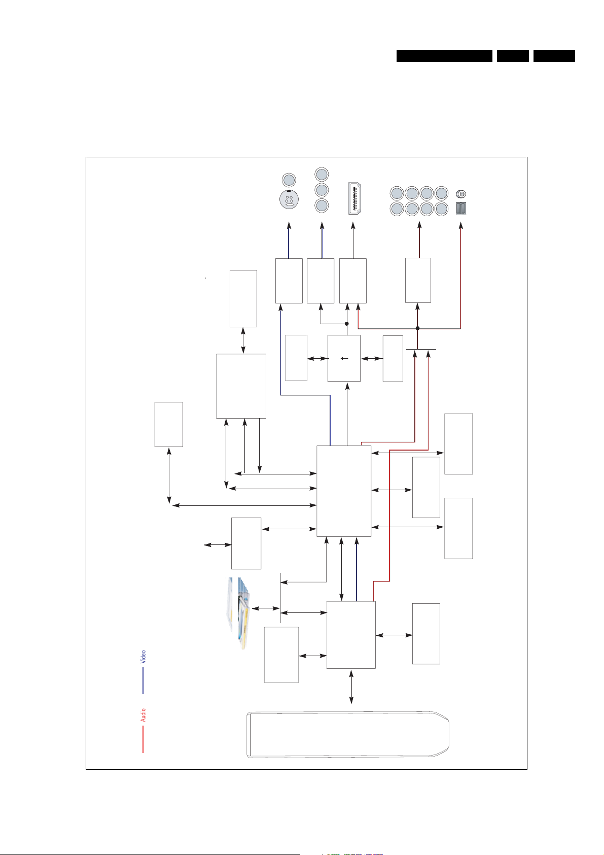
4. Technical Reference
4.1. System
4.1.1. System Block Diagram
Technical Reference
S-V deo / CVBS
YPbPr
BDP9000 4. EN 7
Surr
Front
CT LFE
Down M x 2ch
Flash
Loca Bus
Memory Card
MPEG2
PC Bus
DDR
(64M Byte)
Decoder
MPEG4/VC-1
TS /F
D g ta V deo
Card
Memory
Contro er
DE Bus
V deo DAC
4MB F ash
DE Bus
HDM
V deo DAC
1080p
1080
D g ta V deo
Ana og V deo
Main CPU
BD decoder
UART
D g ta V deo
Transm tter
2S/SPD F
8ch DAC
2S
SPD F
DDR
Tota 320M Byte
From BD Decoder
From DVD Decoder
D g ta Aud o
( 2S/SPD F)
DDR
DDR
DDR
A bus B bus C bus
BD Loader
DDR
(64M Byte)
4MB
DVD
decoder
Flash
Front /F
RC
Figure 4.1-1

EN 8 4. BDP9000
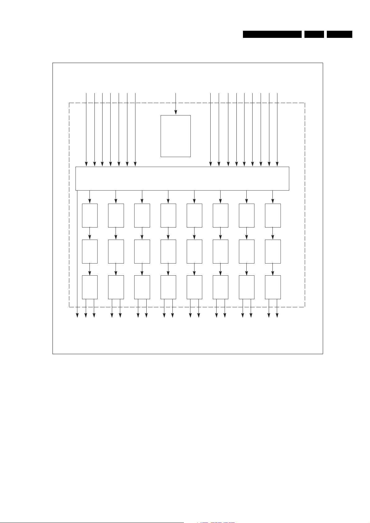
4.1.2. Wiring Diagram
Technical Reference
Figure 4.1-2
4.2. Audio - AK4358 (AIC1)
MCLK
LRCK
BICK
SDTI1
SDTI2
SDTI3
SDTI4
Technical Reference
or I2C
3-wire
Control
Register
DCLK
DSDL1
DSDR1
DSDL2
DSDR2
BDP9000 4. EN 9
DSDL3
DSDR3
DSDL4
DSDR4
I/F
Audio
DATT
PCM
DATT
DATT
DSD
DATT
AK4358
DAC
SCF
DAC
SCF
DZF
LOUT1-
LOUT1+
ROUT1-
ROUT1+
DAC DATT
SCF
LOUT2-
LOUT2+
DAC DATT
SCF
ROUT2-
ROUT2+
Figure 4.2-1
DAC
SCF
LOUT3+
LOUT3-
DAC DATT
SCF
ROUT3-
ROUT3+
DAC DATT
SCF
LOUT4-
LOUT4+
DAC
SCF
ROUT4-
ROUT4+
EN 10 4. BDP9000
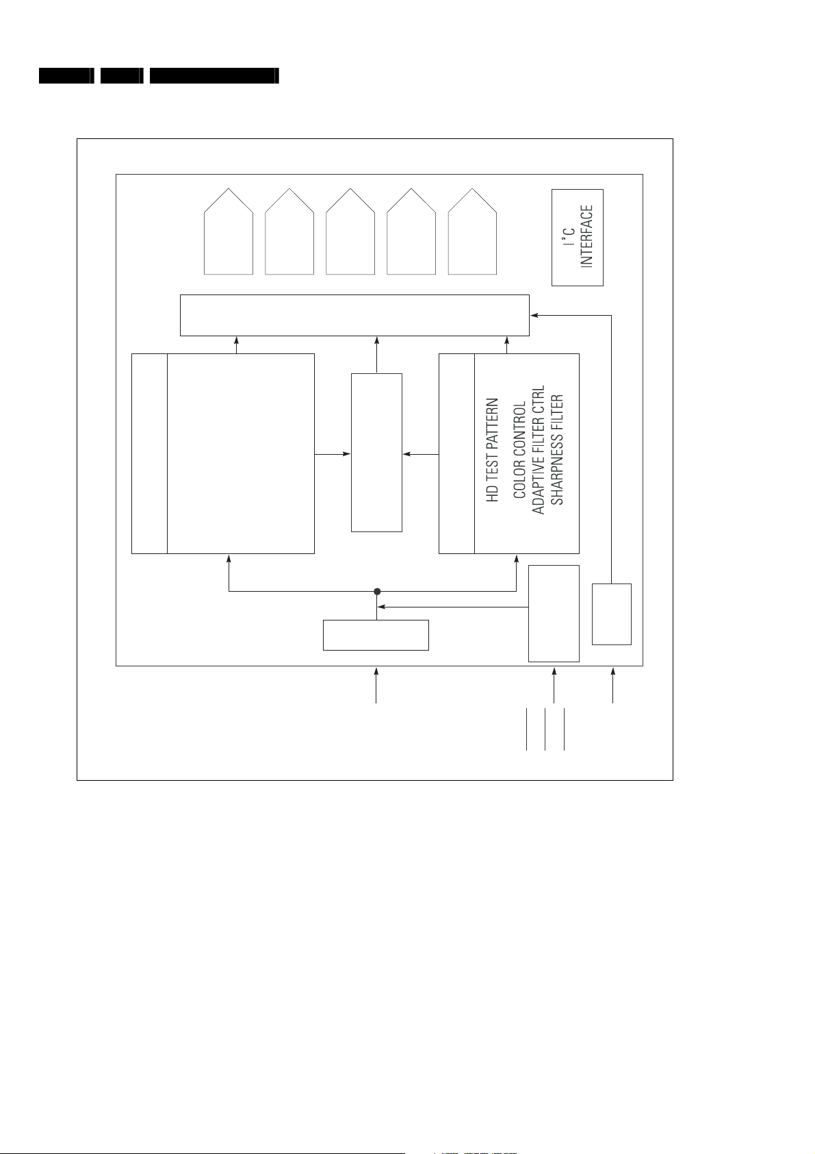
4.3. Video Encoder - ADV7322 (VIC4)
Technical Reference
BRIGHTNESS
COLOR CONTROL
SD CONTROL BLOCK ADV7322
DAC
11-BIT
O
DNR
GAMMA
PROGRAMMABLE
11-BIT
V
FILTERS
DAC
E
R
SD TEST PATTERN
DAC
11-BIT
S
A
M
PROGRAMMABLE
E
D
M
P
RGB MATRIX
U
DAC
11-BIT
I
L
X
DAC
11-BIT
G
N
HD CONTROL BLOCK
TIMING
GENERATOR
PLL
Y7-Y0
C7-C0
S7-S0
Figure 4.3-1
VSYNC
HSYNC
BLANK
CLKIN_B
CLKIN_A
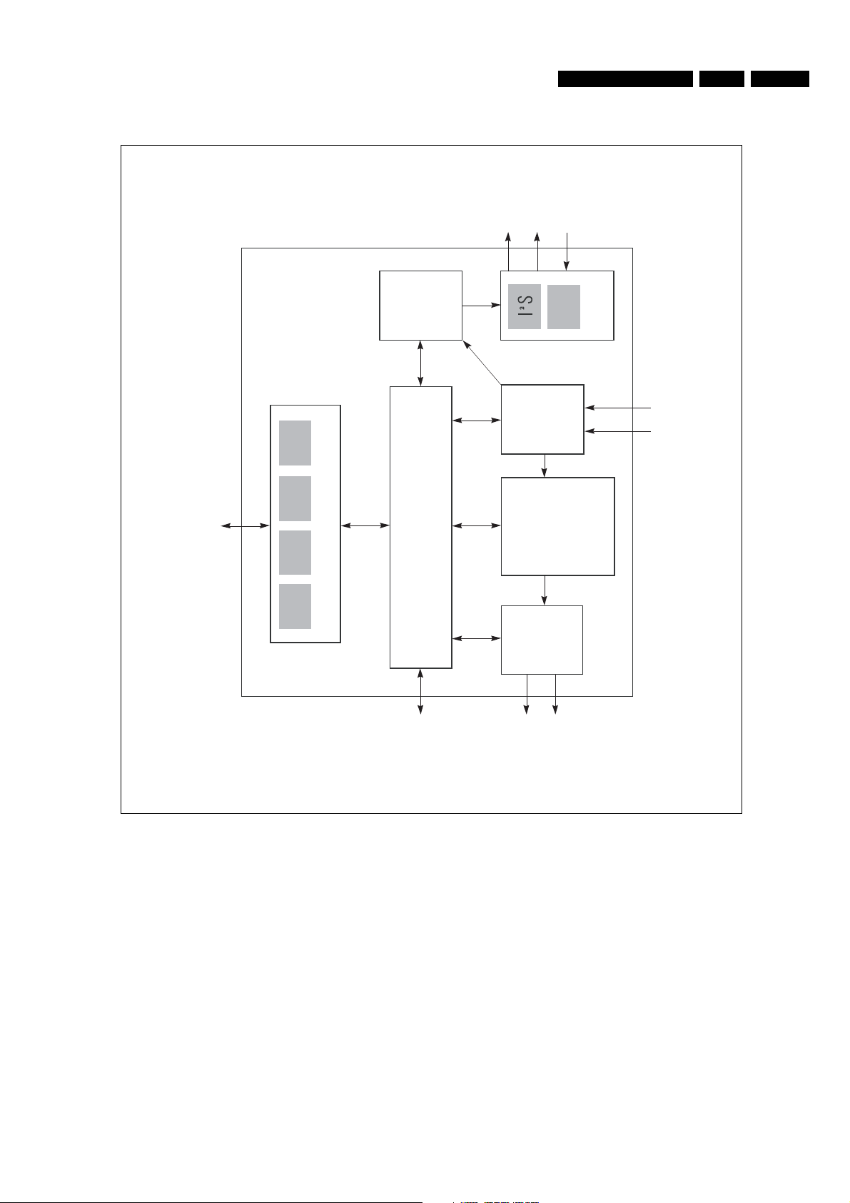
4.4. System Decoder (U1)
Technical Reference
Audio
Out
BDP9000 4. EN 11
Audio In
Gener c
PCI
Control/Status
SPI
GPIO
16-b t
System I/O
Audio
Decoder
Layer
Transport
H.264/VC-1
DDR SDRAM Controller
Post
Video
SPDIF
Aud o /O
Demux
Decoder
/MPEG-2
Proc
Transport/Program/Elementary Stream In
DDR
SDRAM
Digital
Video Out
Figure 4.4-1

EN 12 4. BDP9000
Technical Reference
4.5. Video Driver (SM5302) block diagram (VIC3)
Figure 4.5-1

5. Required Equipment List
Required Equipment List
BDP9000 5. EN 13
Equipment & Facilities
• Remote control
• Stereo Headpho
• External audio a
- audio L/R cinch inputs (x2)
- coaxial SPDIF input
- optical SPDIF input
Cables
• HDMI cable
• S-Video cable
• 2x Audio L/R Chinch cables
• Digital audio coax cable
• Digital audio optical cable
Memor
y Cards / Media
• Compact Flash (C
• Smart Media (SM)
• Secure Digital (SD)
• MultiMedia Card (MMC)
• Memory stick (
• Audio CD
• Video DVD
• Blu-ray disc
(Blu-ray version)
nes (with 6.3 mm Jack Plug)
mplifier with the following connections:
F)
MS)

EN 14 6. BDP9000
Diagnosis and Repair Flowchart
6. Diagnosis and Repair Flowchart
6.1. Overview
Symptom Refer to
No power detected (Standby LED off) Flowchart 1
No digital audio output Flowchart 2
No audio output Flowchart 3
Disc loading error Flowchart 4
Remote control does not work Flowchart 5
No picture Flowchart 6
No Logo screen (HDMI) Flowchart 7
No Logo screen (Component 1080i, 720p, 480p) Flowchart 8
No Logo screen (Component 480i) Flowchart 9
No Logo screen (Video, S-Video) Flowchart 10
BD Flowchart 11
DVD Flowchart 12

Diagnosis and Repair Flowchart
6.2. Flowchart 1: No power detected (Standby LED off)
NO Power Detected
(Stand by LED OFF)
BDP9000 6. EN 15
F01 is normal?
C10 voltage
is normal voltage?
Switching operation
of IC01,IC02 is normal?
Replace IC01, IC02
Yes
Yes
No
No
No
Yes
Change fuse
Change BD01
Check 2st voltage
Figure 6.2-1

EN 16 6. BDP9000
Diagnosis and Repair Flowchart
6.3. Flowchart 2: No digital audio output
There's no Digital Audio Out
Check Current Digital Audio
Setting is PCM.
Yes
Check the Audio Data at
AIC3 pin4 (BD) or
AIC3 pin13 (DVD)
Yes
Check Digital Audio data
at pin 7 of AIC3
(MAIN PCB)
Yes
Check 5V at AIC2 pin14
Yes
No
No
No
No
AUDIO
Check the A/V Receiver
can Decode Current
Bit-Steam
Replace Main PCB
Replace the AIC3
Check the power cable
DATA
Yes
No
Set to Bitstream
Replace the Main PCB
Figure 6.3-1

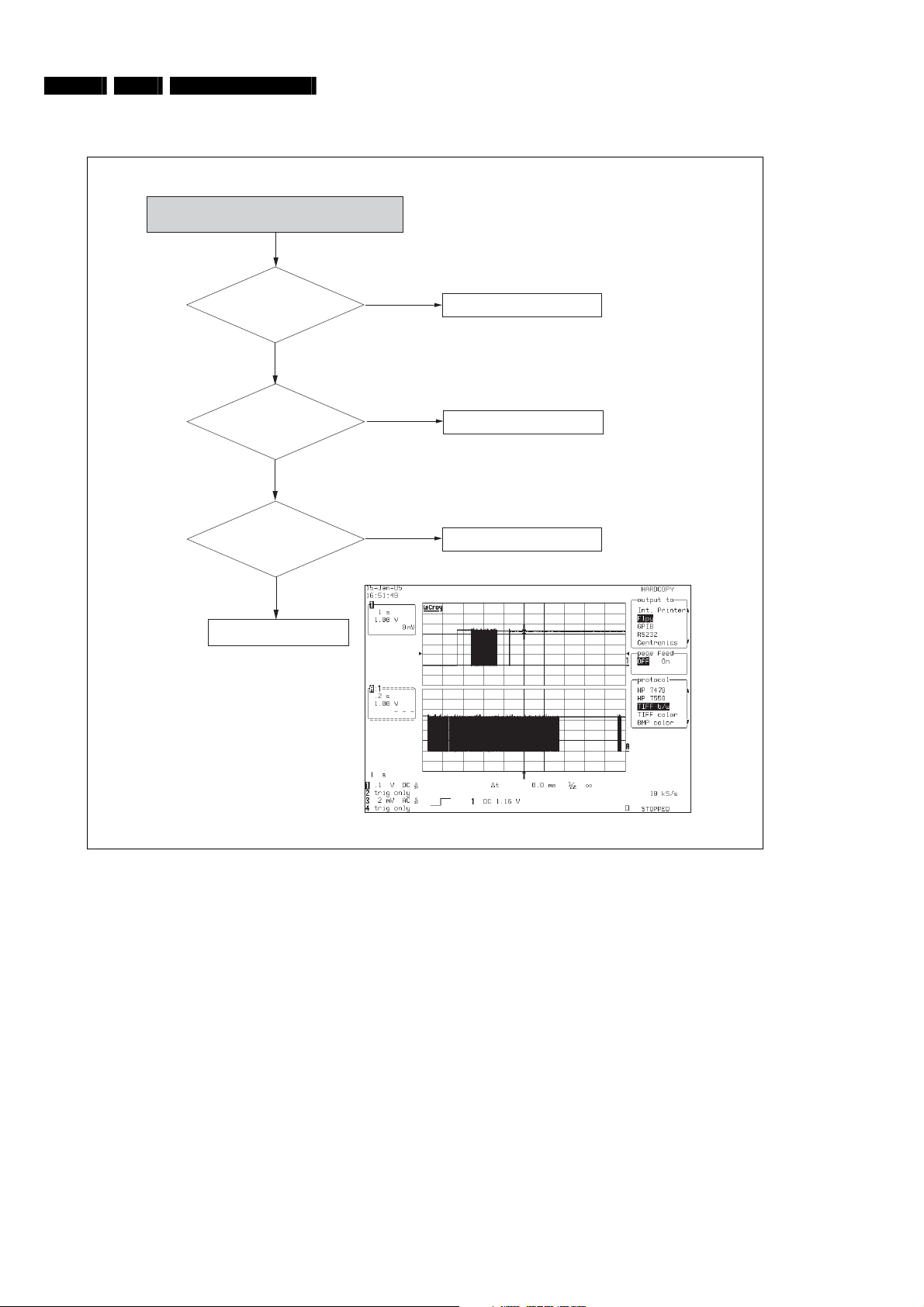
6.4. Flowchart 3: No audio output
There is no Audio Output
Diagnosis and Repair Flowchart
BDP9000 6. EN 17
Check he audio signal
at AIC 6,7,8
No
Check all the signal at
R518,516,514,512
No
Check the audio signal
at pin2,4,6,8, of AIC5
Yes
Check digital clock
at pin 12,14,16,18,of AIC4
Yes
Yes
Yes
No
No
AUDIO DATA
Check the passive parts around
Audio Jack pin
Check the AIC1
Replace Main PCB
Replace MAIN PCB
Check the power cable
Figure 6.4-1
EN 18 6. BDP9000
6.5. Flowchart 4: Disc loading error
Diagnosis and Repair Flowchart
Disc Ioading error
Are Main and deck
power OK?
(5v, 12v)
FFC cable(between main & deck)
Is the 40pin
inserted correctly?
Is the wavefrom
of U10-pin24 normal?
(MAIN PCB)
Change the deck
Yes
Yes
Yes
No
No
No
U10-pin24
Check the power
Reinsert FFC cable correctly
Change the Main board
Figure 6.5-1

Diagnosis and Repair Flowchart
6.6. Flowchart 5: Remote control does not work
Remote control does not work
BDP9000 6. EN 19
Remocon battery
OK?
No
Change the battery
Yes
Is the FFC cable(between
Front panel&Main) OK?
No
Re-insert FFC cable correctly
Yes
U16(Pin5)
Signal OK?
No
Check the U16, R379 or change
the Front panel PCB
Yes
Check the Power of U16 (Pin51)
or change the Main PCB
Figure 6.6-1

EN 20 6. BDP9000
6.7. Flowchart 6: No picture
No Picture
Diagnosis and Repair Flowchart
Logo screen is OK ?
Yes
BD playback picture is OK ?
Yes
DVD playback picture is OK ?
Yes
Clock and data output from
U14 ? (R391, R37,R86)
Yes
Change the Main PCB
No
No
No
No
NO LOGO
BD
DVD
U14, X1 check for soldering error
Figure 6.7-1

Diagnosis and Repair Flowchart
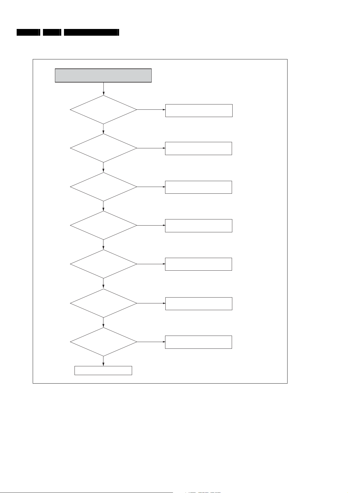
6.8. Flowchart 7: No logo screen (HDMI)
NO LOGO Screen(HDMI)
BDP9000 6. EN 21
Video selection set properly
accords with cable connection
and TV mode ?
Yes
Clock, data and
SYNC output from U1 ?
(EL1, VRN1~6,
VR30,31)
Yes
Clock, data and
SYNC from U601 ?
(R2956, FRN1~6,
R605,606)
Yes
pin2 of HD6 is High ?
(2.0~5.0V)
Yes
No
No
No
No
Check the Video select, cable
connection, TV input mode
U1 check for soldering error
Check U601 power input, X600
oscillation, Memory interface
Check HD6 power input and HDMI
cable connection
data output from HIC1 ?
(pin26,27,29,30,32,33,35,36)
Yes
Defective HDMI cable
No
Check the HIC1 power input and
peripheral devices
Figure 6.8-1
EN 22 6. BDP9000
Diagnosis and Repair Flowchart
6.9. Flowchart 8: No logo screen (Component 1080i, 720p, 480p)
NO LOGO Screen
(Component 1080i, 720p, 480p)
Video selection
accords with cable
connection and TV mode ?
Yes
Clock, data and
SYNC output from U1 ?
(EL1, VRN1~6, VR30,31)
Yes
SYNC output from U707 ?
(pin34,33)
Yes
Clock, data and
SYNC from U601 ?
(R2956, FRN1~6, R605,606)
Yes
Y,Pb,Pr signals
output from VIC4 ?
(pin39,38,37)
No
No
No
No
No
Check the Video select, cable
connection, TV mode
U1 soldering error
Check U707 power Clock (pin18) and ,
SYNC(pin8,9) input
Check U601 power input, X600
oscillation, Memory interface
Check VIC4 power and Reset
(pin33; ÔHighÕ) input
Yes
Y,Pb,Pr signals
output from VIC4 ?
(pin25,21,17)
Yes
Y,Pb,Pr signals are OK from
VIC4 to J5 ?
Yes
Component cable error
No
No
Check VIC4 power input
Check soldering of
peripheral devices
Figure 6.9-1
Diagnosis and Repair Flowchart
6.10. Flowchart 9: No logo screen (Component 480i)
NO LOGO Screen(Component 480i)
BDP9000 6. EN 23
Video selection
accords with cable connection
and TV mode ?
Yes
Clock, data and
SYNC output from U1 ?
(EL1, VRN1~6, VR30,31)
Yes
Y,Pb,Pr signal output from
VIC7 ? (pin39.38.37)
Yes
Y,Pb,Pr signal output from VIC3 ?
(pin25,21,17)
Yes
No
No
No
No
Check the Video select, cable
connection, TV mode
U1 soldering error
Check VIC7 power and
Reset(pin33; ÔHighÕ) input
Check VIC3 power input
Y,Pb,Pr signal is OK from
VIC3 to J5 ?
Ye
Defective Component cable
Pr(Color-bar)
No
Pb(Color-bar)
Check soldering of peripheral
devices
Y(Color-bar)
Figure 4.1-1

EN 24 6. BDP9000
Diagnosis and Repair Flowchart
6.11. Flowchart 10: No logo screen (Video, S-Video)
NO LOGO Screen(Video, S-Video)
Video selection accords
with cable connection
and TV mode ?
Yes
Clock, data and
SYNC output from U1 ?
(EL1, VRN1~6, VR30,31)
Yes
Video and S-Video signal output
from VIC7 ? (pin44,43,42)
Yes
Video and S-Video output
from VIC2 ? (pin13,10,15)
Yes
No
No
No
No
Check the Video select, cable
connection, TV mode
U1 soldering error
Check VIC7 power and Reset
(pin33; ÔHighÕ) input
Check VIC2 power input
Y,Pb,Pr signal is OK from
VIC2 to J4 ?
Yes
Video/S-Video cable error
Y(Color-bar)
No
C(Color-bar)
Check soldering of peripheral
devices
CVBS(Color-bar)
Figure 6.11-1

6.12. Flowchart 11: BD
BD
Diagnosis and Repair Flowchart
BDP9000 6. EN 25
TS Clock, data
and SYNC output from U1 ?
(EL6, R342~344, R348)
Yes
Clock, data and
SYNC output from U20 ?
(RP30, RP31, R518)
Yes
Clock outputs from U42
pin4 ?
Yes
SYNC outputs from
U702 pin8,9 ?
Yes
No
No
No
No
Check U1 power input and Memory
interface
Check U30 power input and Memory
interface
Check U42 power input and
selection signal (pin6; ÔLowÕ)
Check U702 power, Clock (pin43) and
SYNC(pin14,15) input
Clock, data and
SYNC output from U1 ?
(EL1, VRN1~6, VR30,31)
Yes
NO LOGO
No
U1 soldering error
Figure 6.12-1

EN 26 6. BDP9000
6.13. Flowchart 12: DVD
Diagnosis and Repair Flowchart
DVD
PS Clock, data
and SYNC output from U1 ?
(EL6, R342~344, R348)
Yes
Clock, data
output from U20 ?
(RP30, RP31, R518)
Yes
Clock outputs from U42
pin4 ?
Yes
SYNC outputs from
U702 pin8,9 ?
Yes
No
No
No
No
Check U1 power input and Memory
interface
Check U30 power input and Memory
interface
Check U42 power input and
selection signal (pin6; ÔHighÕ)
Check U702 power, Clock (pin43) and
SYNC(pin14,15) input
Clock, data and
SYNC output from U1 ?
(EL1, VRN1~6, VR30,31)
Yes
NO LOGO
No
U1 soldering error
Figure 6.13-1

Software Update and Repair
7. Software Update and Repair
7.1. Introduction
To improve the performance of the BDP9000 Blu-ray Disc Player, Philips will release software updates. This section describes how to
update the software on the BDP9000 Blu-ray Disc Player.
7.2. How to make an update disc?
BDP9000 7. EN 27
1. Download the software update from www.philips.com.
2. Write the softw
Recommended applications Nero Burning, Easy CD Creator
Recommended recording options
Extension name *.REC
Multisession No multisession
File name length Max. of 11 = 8 + 3
Format Mode 1
Character set ISO 9660, Joliet Format
CD Close and Disc-at-once Yes
are update to a CD-RW or CD-R. Refer to the next table for the recommended applications and recording options.
7.3. How to update the software?
CAUTION:
DO NOT DISCONNECT THE POWER CORD FROM THE AC POWER SOURCE
YOU DO, THE SOFTWARE UPDATE PROCESS CAN STOP. IF THE SOFTWARE UPDATE PROCESS STOPS BEFORE THE
SOFTWARE UPDATE IS COMPLETE, THE BDP9000 BLU-RAY DISC PLAYER. CAN BE DAMAGED.
CAUTION:
IF AN OUTAGE OCCURS DURING THE SOFTW
THE SOFTWARE PROCESSS STOPS BEFORE THE SOFTWARE UPDATE IS COMPLETE, THE BDP9000 BLU-RAY DISC PLAYER
CAN BE DAMAGED.
CAUTION:
DO NOT OPEN THE DISC TRAY DURING THE SOFTWARE UPD
PROCESS CAN STOP. IF THE SOFTWARE PROCESSS STOPS BEFORE THE SOFTWARE UPDATE IS COMPLETE, THE
BDP9000 BLU-RAY DISC PLAYER CAN BE DAMAGED.
CAUTION:
MAKE SURE THAT THE UPDATE DISC IS CLEAN. DIRT AND SCRATCHES CAN STOP THE SOFTWARE UPDATE PROCESS. IF
THE SOFTWARE UPDATE PROCESS STO
CAN BE DAMAGED.
1. Press the O
• The disc tray opens.
2. Put the update disc in the disc tra
3. Press the OPEN/
• The disc tray
4. Wait until the screen sho
5. On the remote c
• The actual software updat
6. Wait until the screen sho
7. Remove the update disc from the
8. Press the STA
• The ST
9. Press the STA
• The ST
10. Check new
11. Repeat the steps 1-10 to up
12. Repeat the steps 1-10 to up
CLOSE button.
PEN/
CLOSE button again.
closes.
ontrol, press the OK button.
NDBY-ON button.
ANDBY-ON light comes on as red.
NDBY-ON button again.
ANDBY-ON light comes on as blue and the disc tray closes.
and old version (numbers).
ws the following text (1 -2 minutes): Do you want to update Main F/W?
e starts.
ws the following text (5 - 6 minutes): Main F/W is succesfully updated.
date the DVD firmware (Sub F/W).
date the ODD firmware (Loader F/W).
ARE UPDATE P
EFORE THE SOFTWARE UPDATE IS COMPLETE, THE BDP9000 BLU-RAY DISC
PS B
y with the label on top.
disc tray.
DURING THE SOFTWARE UPDATE PROCESS. IF
ROCESS, THE SOFTWARE UPDATE PROCESS CAN STOP. IF
A
TE PROCESS. IF YOU DO, THE SOFTWARE UPDATE

EN 28 8. BDP9000
Mechanical Instructions
8. Mechanical Instructions
8.1. Removal of the top cover
1. Remove the five screws (A, B, C).
2. Lift the top cover.
A
B
C
Figure 8.1-1
8.2. Removal of the front panel assembly
1. Remove the top cover (refer to 8.1).
2. Release the seven hooks (A, B, C, D)
3. Release the front panel assy. (E).
A
Mechanical Instructions
B(2x)
BDP9000 8. EN 29
C
D(3x)
E
Figure 8.2-1

EN 30 8. BDP9000
8.3. Removal of the optical drive
1. Remove the front panel assy. (refer to 8.2).
2. Remove the four screws (A, B).
3. Lift the optical drive (C).
Mechanical Instructions
A(2x)
Figure 8.3-1
B(2x)
C
 Loading...