

Philips BDL5551EL Schematic
55″ Flat Wide Monitor
Service
BDL5551EL/00
Service
Service
Description
Table of Contents............................................………….1
Revision List................................................…………….2
Safety Instructions………………..................................3
1. General Specifications…............................................7
2. Flat Wide Monitor Description…………....................11
3. Operation Instructions…...........................................12
3.1 Control Panel………………….…….……………....12
3.2 Input/ Output Terminal ....................................…....13
3.3 Remote Control………………………………….……15
3.4 OSD Menu……………….................................16
4. Input/output Specification..........................………….28
4.1 Input Signal Connector...........................…………..28
4.2 Factory Preset Display Modes................................30
4.3 Pixel Defect Policy……………………………………31
4.4 Failure Mode of Panel …………………………….…34
5. Block Diagram….......................................................33
5.1 Scaler Board….......................................................33
5.2 Power Board….......................................................36
6. Schematic Diagram..................................................37
6.1 Scaler Board……………………………..…………37
6.2 Power Board....................................................…...54
6.3Key Board………………………………………....55
6.4 IR Board…….…………………….………………….56
Page Description Page
6.5 SUB Board…….……………………..…………………55
6.6 CONNECTOR Board…….…………………………61
6.7 FAN Board…….……. ….………………………..63
7. PCB Layout……………………………………………...64
7.1 Scaler Board…………………………………….……..64
7.2 Power Board…………………………………...………65
7.3 Key Board……………….……………………………..67
7.4 IR Board………………………………………………...67
7.5 USB Board………...……………………………………68
7.6 CONNECTOR Board…….…………………………69
7.7 FAN Board…….……. ….………………………69
8. Wiring Diagram……………………………….…….…..70
9. Scaler Board Overview……………………….….…....71
10. Mechanical Instructions……………………………....72
11. Trouble Shooting…….…….………………….………77
12. ISP Instructions...…...................................................79
13. DDC Instructions...…...............................................94
14. White Balance, Luminance Adjustment……............114
15. Monitor Exploded View…........................................116
16. Recommended & Spare Parts List...……................117
17. General Product Specification…………….……….122
SAFETY NOTICE
ANY PERSON ATTEMPTING TO SERVICE THIS CHASSIS MUST FAMILIARIZE HIMSELF WITH THE
CHASSIS AND BE AWARE OF THE NECESSARY SAFETY PRECAUTIONS TO BE USED WHEN
SERVICING ELECTRONIC EQUIPMENT CONTAINING HIGH VOLTAGES.
CAUTION: USE A SEPARATE ISOLATION TRANSFOMER FOR THIS UNIT WHEN SERVICING
REFER TO BACK COVER FOR IMPORTANT SAFETY GUIDELINES
Copyright 2012 Philips Consumer Lifestyle Subject to modification ○K Feb.07, 2012
2
Revision List
Version Release Date Revision History
A00 Feb.07,2013 Initial release, Draft Version
3
Safety Instructions
Warnings and Precautions
CAUTION: TO REDUCE THE RISK OF ELECTRIC SHOCK, DO NOT REMOVE COVER (OR BACK). NO USER
SERVICEABLE PARTS INSIDE. REFER SERVICING TO QUALIFIED SERVICE PERSONNEL.
This symbol indicates high voltage is present inside. It is dangerous to make any kind of contact with any
inside part of this product.
This symbol alerts you that important literature concerning operation and maintenance has been included
with this product.
Note to CATV system installer: This reminder is provided to call CATV system installer’s attention to Article
820-40 of the National Electrical Code (Section 54 of Canadian Electrical Code, Part I), that provides guidelines for
proper grounding and, in particular, specifies that the cable ground shall be connected to the grounding system of
the building as close to the point of cable entry as practical.
CAUTION: FCC/CSA regulations state that any unauthorized changes or modifications to this equipment may void
the user’s authority to operate it.
CAUTION: To prevent electric shock, match the wide blade of plug to the wide slot, and fully insert the plug.
IMPORTANT: One Federal Court has held that unauthorized recording of copyrighted TV programs is an
infringement of U.S. copyright laws. Certain Canadian programs may also be copyrighted and any unauthorized
recording in whole or in part may be in violation of these rights.
TO PREVENT DAMAGE WHICH MAY RESULT IN FIRE OR ELECTRIC SHOCK HAZARD, DO NOT EXPOSE
THIS APPLIANCE TO RAIN OR MOISTURE.
Read and follow these instructions when connecting and using your computer monitor:
Unplug the monitor if you are not going to use it for an extensive period of time.
Unplug the monitor if you need to clean it with a slightly damp cloth. The screen many be wiped with a dry cloth
when the power is off. However, never use alcohol, solvents or ammonia-based liquids.
Consult a service technician if the monitor does not operate normally when you have followed the instructions in
this manual.
The casing cover should be opened only by qualified service personnel.

4
Keep the monitor out of direct sunlight and away from stoves or any other heat source.
Remove any object that could fall into the vents or prevent proper cooling of the monitor’s electronics.
Do not block the ventilation holes on the cabinet.
Keep the monitor dry. To avoid electric shock, do not expose it to rain or excessive moisture.
If turning off the monitor by detaching power cable or DC power cord, wait for 6 seconds before attach the
power cable or DC power cord for normal operation.
To avoid the risk of shock or permanent damage to the set do not expose the monitor to rain or excessive
moisture.
When positioning the monitor, make sure the power plug and outlet are easily accessible.
IMPORTANT: Always activate a screen saver program during your application. If a still image in high contrast
remains on the screen for an extended period of time, it may leave an ‘after-image’ or ‘ghost image’ on the front
of the screen. This is a well-known phenomenon that is caused by the shortcomings inherent in the LCD
technology. In most cases the afterimage will disappear gradually over a period of time after the power has
been switched off. Be aware that the after-image symptom cannot be repaired and is not covered under
warranty.
Regulatory Information
CE Declaration of Conformity
MMD declare under our responsibility that the product is in conformity with the following standards.
EN60950-1: 2001 (Safety requirement of Information Technology Equipment)
EN55022: 2006 (Radio Disturbance requirement of Information Technology Equipment)
EN55024:1998+A:2001+A2: 2003 (Immunity requirement of Information Technology Equipment)
EN61000-3-2:2006 (Limits for Harmonic Current Emission)
EN61000-3-3:1995+A1: 2001+A2:2005 (Limitation of Voltage Fluctuation and Flicker) following provisions of
directives applicable.
2006/95/EC (Low Voltage Directive)
2004/108/EC (EMC Directive)
93/68/EEC (Amendment of EMC and Low Voltage Directive) and is produced by a manufacturing organization
on ISO9000 level.
Federal Communications Commission (FCC) Notice (U.S. Only)
This equipment has been tested and found to comply with the limits for a Class B digital device, pursuant
to Part 15 of the FCC Rules. These limits are designed to provide reasonable protection against harmful
interference when the equipment is operated in a commercial environment. This equipment generates,
uses and can radiate radio frequency energy and, if not installed and used in a residential area is likely to
cause harmful interference in which case the user will be required to correct the interference at his own
expense.
Changes or modifications not expressly approved by the party responsible for compliance could void the
user’s authority to operate the equipment.
sTo
HCA
n
o
s
s
B
Q
T
T
n
v
A
R
p
m
m
o
u
S
N
a
a
R
o
t
R
F
R
e
o
e
s
o
w
w
EBROGRE
TpG
Tle
Tle
s
c
L
F
t
n
s
s
p
e
e
s
n
h
d
m
A
”
O
s
G
c
N
c
o
E
O
d
m
o
f
d
e
n
u
e
s
a
O
h
E
c
C
b
v
e
n
h
v
3
d
n
s
E
o
d
h
o
n
h
t
3
T
l
e
e
c
E
a
e
o
r
R
t
u
c
a
f
e
t
o
a
m
c
n
d
p
a
o
A
k
h
h
e
5
U
e only RF
prevent da
oisture.
m
T
IS CLASS
USING E
I
formatio
hielded cabl
mage which
DIGITAL
UIPMENT
This
device com
1)
his device
2)
his device
o
peration.
for UK
e that was s
may result i
PPARATU
EGULATIO
lies with P
ay not caus
ust accept
nly
WA
Imp
This
this
upplied with
n fire or sho
MEETS A
S.
rt 15 of the
e harmful in
ny interfere
NING - Thi
rtant:
apparatus i
ype of plug
the monitor
k hazard, d
L REQUIR
CC Rules.
erference.
ce receive
appliance
supplied wi
roceed as f
when conne
not expos
MENTS OF
peration is
, including i
ust be eart
th an appro
llows:
cting this m
this applia
THE CANA
subject to t
terference
ed.
ed mould 1
nitor to a c
ce to rain o
DIAN INTE
e following
hat may ca
A plug. To
mputer devi
excessive
FERENCE-
wo conditio
se undesire
hange fuse
e.
s:
in
N
te: The se
el
ewhere.
ered plug m
1.
2.
3.
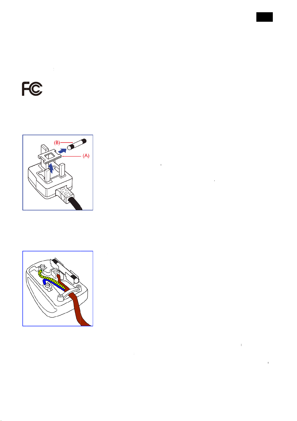
If th
appr
If th
a fu
st be destr
Ho
The
BLU
1.
emove fus
it new fuse
efit the fus
fitted plug i
priate 3-pi
mains plug
e is used, t
yed to avoi
to connect
ires in the
- “NEUTR
WN - “LIVE
EN & YELL
he GREEN
lug which i
REEN or
cover and
which shoul
cover.
not suitabl
plug fitted i
contains a f
e fuse at th
a possible
a plug
ains lead
L” (“N”)
(“L”)
W - “EART
AND YELL
marked wit
REEN & Y
use.
be a BS 1
for your so
its place.
se, this sho
distribution
hock hazar
re colored i
H” (“E”)
W wire mu
the letter “
LLOW.
62 5A, A.S.
cket outlets,
uld have a v
board shou
should it b
accordanc
t be conne
” or by the
.A. or BSI
it should be
alue of 5A. I
d not be gr
inserted in
with the fol
ted to the te
arth symb
pproved ty
cut off and
a plug with
ater than 5
o a 13A soc
lowing code
rminal in the
l or colored
e.
n
ut
.
et
:
2.
he BLUE w
tter “N” or
3.
he BROW
tter “L” or
Befo
re replacing
the
heath of the
ire must be
olored BLA
wire must
olored RED.
the plug co
lead - not si
onnected t
K.
e connecte
er, make ce
mply over t
the termin
to the term
rtain that th
e three wire
l which is m
inal which
cord grip is
s.
rked with t
arked with t
clamped ov
e
e
r

6
North Europe (Nordic Countries) Information
End-OF-Life Disposal
Your new TV/Monitor contains materials that can be recycled and reused. Specialized companies can recycle your
product to increase the amount of reusable materials and to minimize the amount to be disposed of.
Please find out about the local regulations on how to dispose of your old monitor from your local Philips dealer.
For Customers in Canada and USA
This product may contain lead and/or mercury. Dispose of in accordance to local-state and federal regulations.
For additional information on recycling contact www.eia.org (Consumer Education Initiative)
Waste Electrical and Electronic Equipment-WEEE
Attention users in European Union private households
This marking on the product or on its packaging illustrates that, under European Directive
2002/96/EG governing used electrical and electronic appliances, this product may not be
disposed of with normal household waste. You are responsible for disposal of this
equipment through a designated waste electrical and electronic equipment collection. To
determine the locations for dropping off such waste electrical and electronic, contact your
local government office, the waste disposal organization that serves your household or the
store at which you purchased the product.
Attention Users in United States:
Like all LCD products, this set contains a lamp with Mercury. Please dispose of according to all Local, State and
Federal Laws. For the disposal or recycling information, contact: www.mygreenelectronics.com or www.eiae.org.
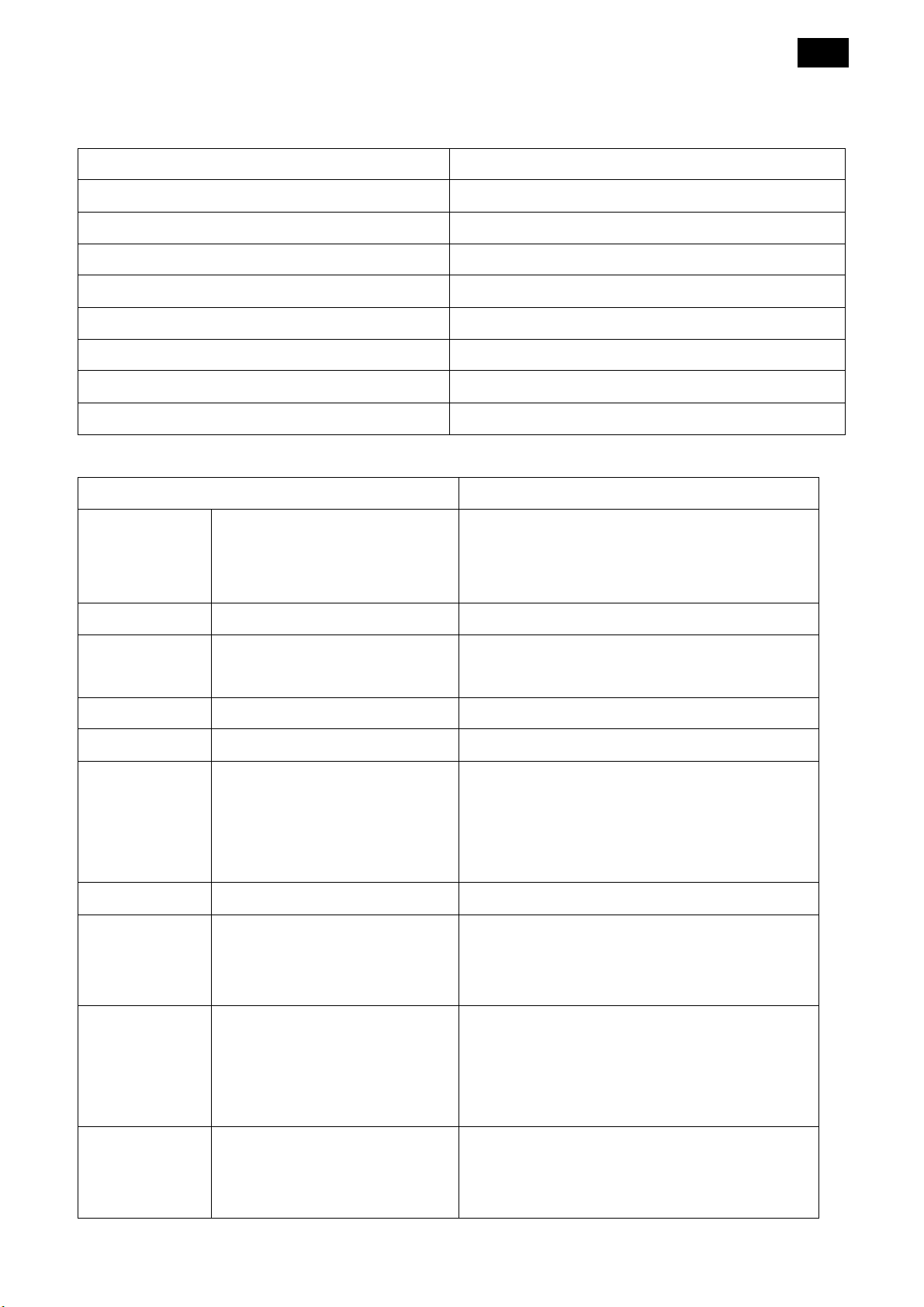
1. General Specifications
BDL5551EL
Display
Item Specifications
Screen Size (Active Area) 54.6” (138.7cm) LCD
Aspect Ratio 16:9
Number of pixels 1920 (H) x 1080 (V)
Pixel pitch 0.21 (H) x 0.63 (V) [mm]
Displayable colors 1073M colors
Brightness (typical) 450 cd/m2
Contrast ratio (typical) 4000:1
Viewing angle 178 degrees (CR>10)
In/Out Terminals
Item Specifications
7
Speaker Output Internal Speakers
External Speakers
Audio Output RCA Jack x 2 0.5V [rms] (Normal) / 2 Channel (L+R)
Audio Input RCA Jack x 2
3.5 mm Stereo x 1
RS232C D-Sub Jack x 2 (9 pin) TXD + RXD (1:1)
RJ-45 RJ-45 Jack x 1 (8 pin) 10/100 LAN Port
HDMI Input HDMI Jack x 1 (Type A) (18 pin) Digital RGB: TMDS (Video + Audio)
DVI-D Input DVI-D jack Digital RGB: TMDS (Video)
VGA Input D-Sub Jack x 1 (15 pin) Analog RGB: 0.7V [p-p] (75Ω), H/CS/V: TTL
10W (L) + 10W (R) [RMS]/8Ω
1 Way 1 Speaker System
82 dB/W/M/160 Hz ~ 13 KHz
0.5V [rms] (Normal) / 2 Channel (L+R)
MAX: Video - 720p, 1080p, 1920 x 1080/60 Hz
(WUXGA) Audio - 48 KHz/ 2 Channel (L+R)
Supports LPCM only
(2.2kΩ), SOG: 1V [p-p] (75Ω)
DVI-I (DVI-D &
VGA) Output
Component
Input
MAX: 720p, 1080p, 1920 x 1080/60 Hz (WUXGA)
DVI-I Jack x 1 (29 pin) Digital RGB: TMDS (Video)
Analog RGB: 0.7V [p-p] (75Ω), H/CS/V: TTL
(2.2kΩ), SOG: 1V [p-p] (75Ω)
MAX: 720p, 1080p, 1920 x 1080/60 Hz (WUXGA)
BNC Jack x 3 Y: 1V [p-p] (75Ω), Pb: 0.7V [p-p] (75Ω), Pr: 0.7V
[p-p] (75Ω)
MAX: 480i, 576i, 480p, 576p, 720p, 1080i, 1080p
8
Video Input BNC x 1 (Share with
Component_Y)
Displayport Input Displayport Jack x 1 (20 pin) Digital RGB: TMDS (Video + Audio)
USB Input USB Jack x 1 USB 2.0
Composite 1V [p-p] (75Ω)
MAX: Video - 720p, 1080p, 1920 x 1080/60 Hz
(WUXGA) Audio - 48 KHz/ 2 Channel (L+R)
Supports LPCM only
USB Flash device (Picture, Audio, Video)
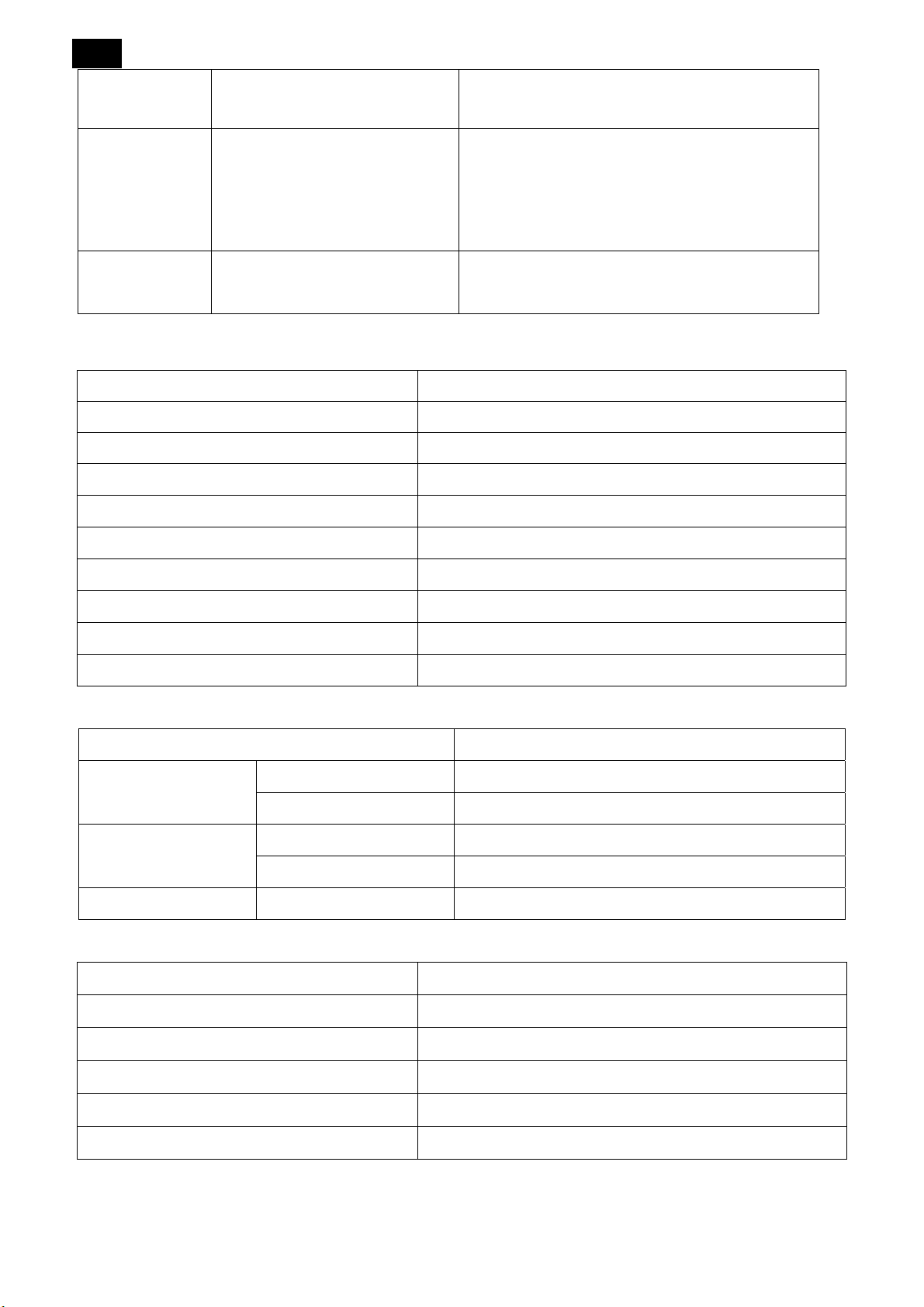
General
Item Specifications
Power Supply AC 100 ~ 240V, 50 ~ 60Hz
Power Consumption (Max) 160W
Power Consumption (typ.) 110W
Power Consumption (Standby & Off) <0.1W (RS232 in active)
Dimensions (With Stand) [W x H x D] 1244.4 x 770.6 x 400 mm
Dimensions (Without Stand) [W x H x D] 1244.4 x 715.2 x 69 mm
Weight (With Stand) 32.6 Kg
Weight (Without Stand) 30.6 Kg
Gross Weight (Without Stand) 38.4 Kg
Environmental Condition:
Item Specifications
Temperature Operational 0 ~ 40°C
Storage -20 ~ 60°C
Humidity Operational 20 ~ 80% RH (No condensation)
Storage 5 ~ 95% RH (No condensation)
Altitude Operational 0 ~ 3,000 m
Internal Speaker:
Item Specifications
Type 1 Way 1 Speaker
Input 10 W (RMS)
Impedance 8Ω
Output Sound Pressure 82 dB/W/M
Frequency Response 160 Hz ~ 13 KHz
Note: Technical specifications are subject to change without notice.
A
9
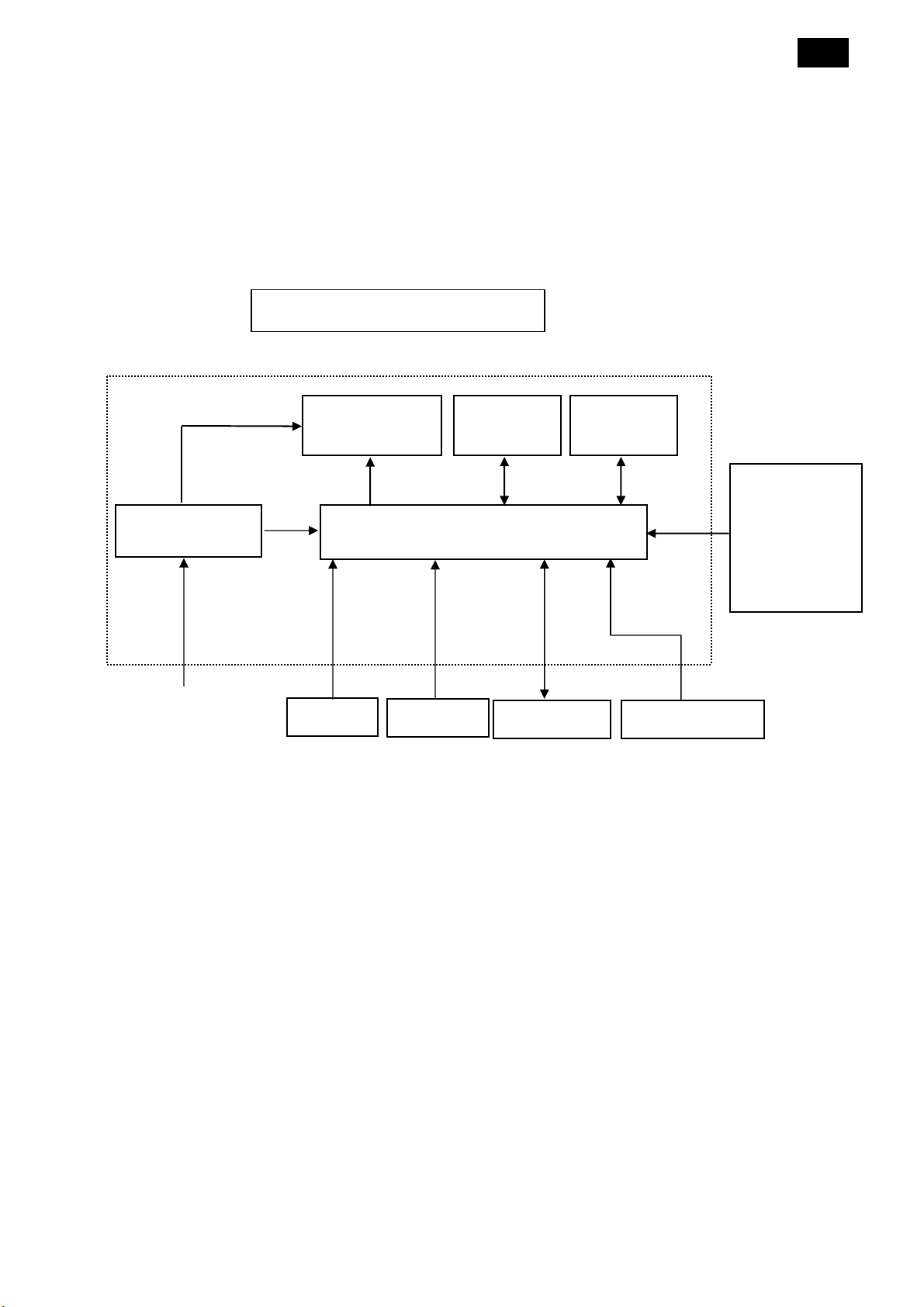
2. Flat Wide Monitor Description
The Flat Wide monitor will contain a scaler board, a power board, a connection board, a FAN board, a SUB board
an IR board and a key board. The scaler board houses the flat panel control logic, brightness control logic and
DDC.
The power board will provide AC to DC Inverter voltage to drive the backlight of panel and the scaler board chips
each voltage.
Flat Wide Monitor Block Diagram
CCFL Drive.
Power Board
Flat Panel and
CCFL backlight
SUB Board
Scaler Board
Connection
Board
RS232
Connector For
white balance
adjustment in
factory mode
C-IN
90V ~ 264V
IR Board
Key Board
FAN Board
HOST Computer
10
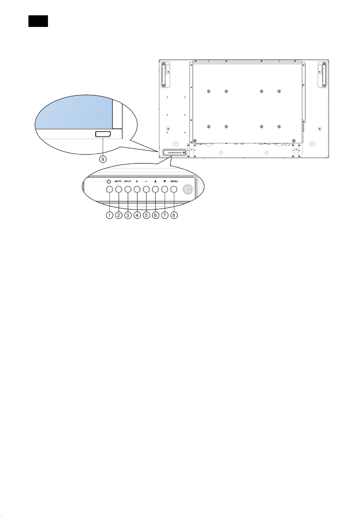
3. Operating Instructions
3.1 Control Panel
1. POWER Button
Use this button to turn the display on or put the
display to standby.
2. Mute Button
Switch the audio mute ON/OFF.
3. INPUT Button
Use this button to select the input source.
4. [+] Button
Increase the adjustment while OSD menu is on, or
increase the audio output level while OSD menu is
off.
Used as [SET] button in the On-Screen-
Display menu,
5. [-] Button
Decrease the adjustment while OSD menu is on, or
decrease the audio output level while OSD menu is
Return to previous menu while OSD menu is on, or
to activate the OSD menu when the OSD menu is
off.
Note:
“Keyboard Control Lock Mode”: This function
completely disables the access to all Keyboard
Control functions. To enable or disable the
keyboard control lock, press both “[▲]” and “[▼]”
buttons and hold down continuously for more than 3
(three) seconds.
9. Remote Control Sensor and Power Status
Indicator
Receives command signals from the remote
control
Indicates the operating status of the display
without OPS.
off.
6. [▲] Button
Move the highlight bar up to adjust the selected
item while OSD menu is on.
7. [▼] Button
Move the highlight bar down to adjust the selected
item while OSD menu is on.
8. MENU Button
- Lights green when the display is turned on
- Lights red when the display is in standby
mode
- Lights amber when the display enters APM
mode
- When (SCHEDULE) is enable, the light blinks
green and red
- If the light blinks red, it indicates that a failure
11
has been detected
- Lights Off when the main power of the display
is turned off.
• Indicates the operating status of the display with
OPS:
- Lights green when the display is on, but the
OPS is off
- Lights blue when the display and the OPS is
on
- Lights red when the display is in standby
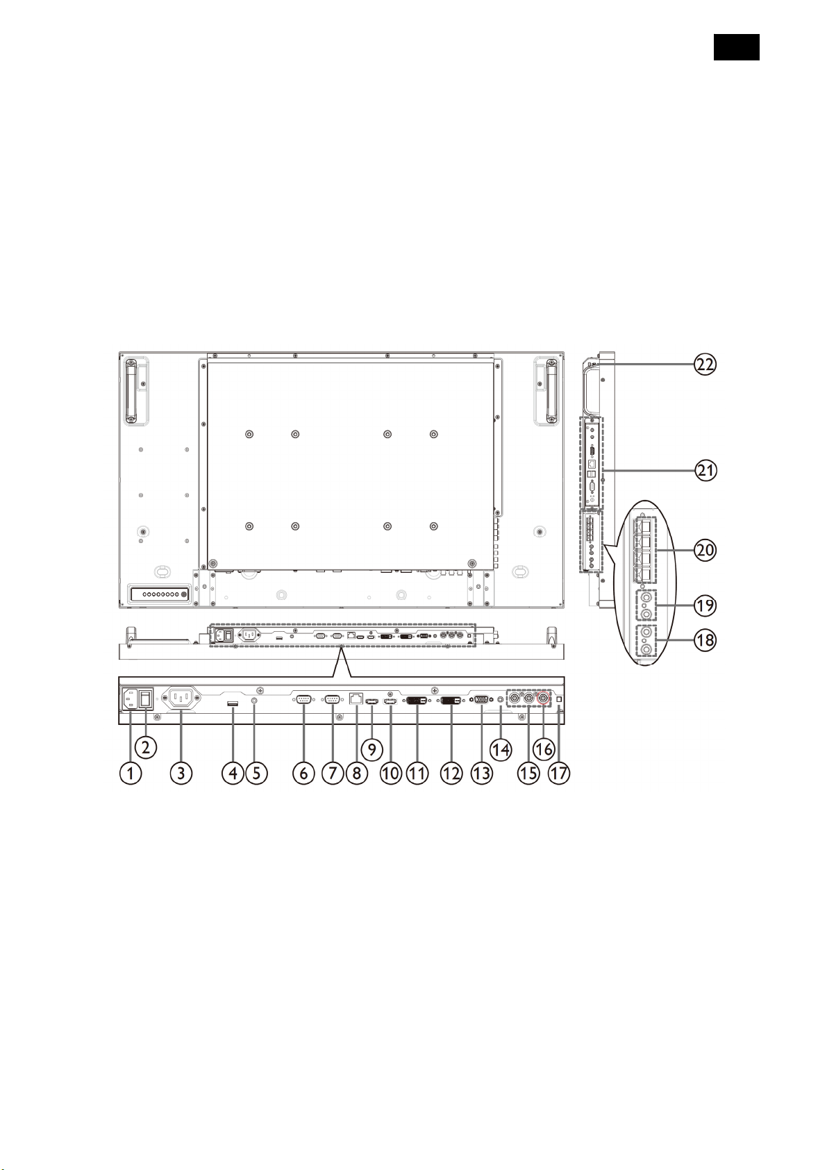
3.2 Input/ Output Terminal
mode
- --Lights amber when the display enters APM
mode
- --When {SCHEDULE} is enabled, the light
blinks green and red
- --If the light blinks red, it indicates that a
failure has been detected
- --Lights off when the main power of the
display is turned off
1. AC IN
AC power input from the wall outlet.
2. MAIN POWER SWITCH
Switch the main power on/off.
3. AC OUT
AC power supply to the AC IN jack of a media
player.
4. USB
Connect your USB storage device.
5. IR pass through:
Outputs the remote control IR signal of set-top box
to a external set-top box through 3.5mm jack cable.
6. RS232C OUT
RS232C network output for the loop-through
function.
7. RS232C IN
RS232C network input for the loop-through
function.
8. RJ-45
LAN control function for the use of remote control
signal from control center.
9. HDMI IN
HDMI video/audio input.
10. DisplayPort

12
DisplayPort video input.
Internal speaker on/off switch.
11. DVI IN
DVI-D video input.
12. DVI OUT / VGA OUT
DVI or VGA video output.
13. VGA IN (D-Sub)
VGA video input.
14. VGA AUDIO IN
Audio input for VGA source (3.5mm stereo phone).
15. COMPONENT IN (BNC)
Component YPbPr video source input.
16. Y/CVBS
Video source input.
17. SPEAKER SWITCH
18. AUDIO IN
Audio input from external AV device (RCA).
19. AUDIO OUT (RCA)
Audio output from the AUDIO IN jack to an external
AV device.
20. SPEAKERS OUT
External speakers output.
21. OPS SLOT
Slot for installing the optional OPS module.
22. KENSINGTON LOCK
Used for security and theft prevention.
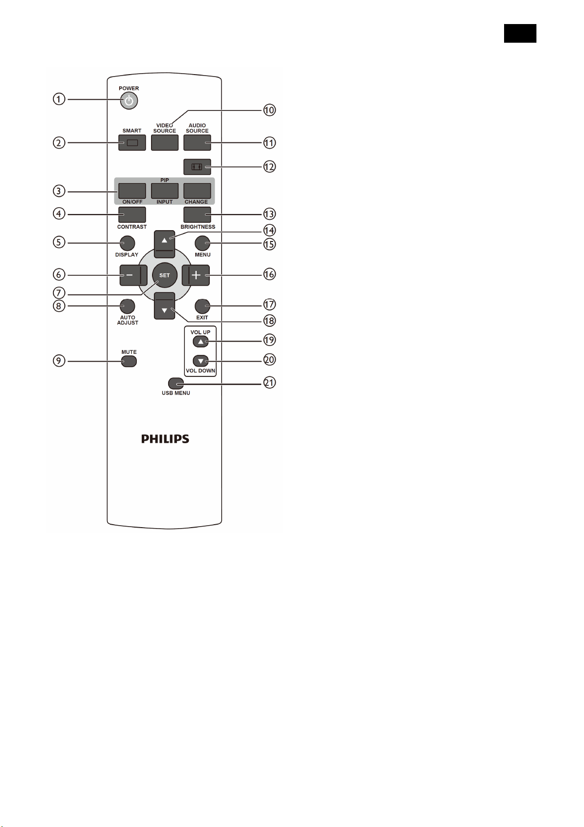
3.3 Remote Control
13
mode)
Cinema: Used for movies(only for Video mode)
3. [PIP] (Picture In Picture) Button
[ON/OFF]: Turn PIP mode ON/OFF.
[INPUT]: Select the input signal for the sub
picture.
[CHANGE]: Toggle between the main picture and
sub picture.
4. [CONTRAST] Button:
Press to activate Contrast Menu. Press the [+] or
[-] button to adjust the value. Press [MENU]
button to confirm and exit.
5. [DISPLAY] Button
Press to turn on/off the information OSD displayed
1. [POWER] Button
Press to switch on the display from standby mode.
Press again to turn it off and back into standby
mode.
2. [SMART] Button
Press to activate Smart Menu. Press [▲] or [▼]
button to select menu options. Press [SET] button
to confirm and exit selection.
Standard: Used for normal images (factory
setting)
Highbright: Used for moving image such as
video
sRGB: Used for text based images(only for PC
on the upper right corner of the screen.
6. [-] Button
Press to move the selection left in OSD menu.
Press to decrease the value in OSD menu.
Press to move the sub picture left in PIP mode.
7. [SET] Button
Press to activate the setting inside the OSD menu.
8. [AUTO ADJUST] Button
Press to run the Auto Adjust function.
Note: This button is functional for VGA input only.
9. [MUTE] Button
Press to turn the mute function on/off.
10. [VIDEO SOURCE] Button
Press to toggle Video Source Menu. Press [▲] or
[▼] button to select one of the video sources
among Displayport, DVI-D, VGA, HDMI,
Component, Video, Card OPS, or USB. Press
[SET] button to confirm and exit.
11. [AUDIO SOURCE] Button
Press to toggle Audio Source Menu. Press [▲] or
[▼] button to select one of the audio sources
among Displayport, HDMI, AUDIO1, AUDIO2,
USB or Card OPS. Press [SET] button to confirm
and exit.
14
12. Picture Format button
Press to switch screen aspect ratio.
For PC signal: Full, Normal, Custom and Real.
For Video signal: Full, Normal, Dynamic, Custom,
Real, and 21:9.
13. [BRIGHTNESS] Button
Press to toggle Brightness Menu. Press [+] or [-]
button to adjust the value. Press [MENU] button to
confirm and exit.
14. [▲] Button
Press to move the selection up in OSD menu.
Press to move the sub-picture up in PIP mode.
15. [MENU] Button
Press to turn the OSD menu on/off
16. [+] Button
Press to move the selection right in OSD menu.
Press to increase the value in OSD menu.
Press to move the sub-picture right in PIP mode
17. [EXIT] Button
Press to turn back to the previous OSD menu.
18. [▼] Button
Press to move the selection down in OSD menu.
Press to move the sub- picture down in PIP mode.
19. [VOL UP] Button
Press to increase the audio output level.
20. [VOL DOWN] Button
Press to decrease the audio output level
21. [USB MENE] Button
Press to enter the USB menu for the USB input.
3.4 OSD Men
3.4.1 Navigating the OSD Menu
Using the remote control
1. Press [MENU] button on the remote control to
display the OSD menu.
2. Press [▲] or [▼] button to choose the item you
5. Press [EXIT] button to return to the previous menu,
or press [MENU] button to exit the OSD menu
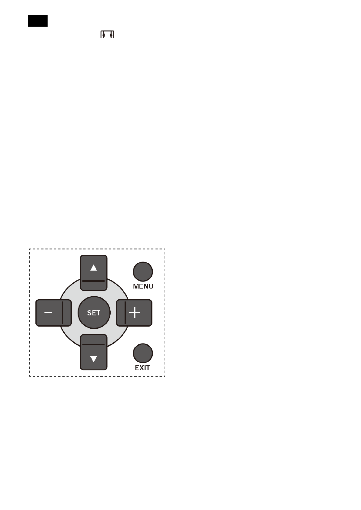
Using the display’s control button
1. Press [MENU] button to display the OSD menu.
2. Press [+] or [-] button to choose the item you want
to adjust.
3. Press [+] button to enter the submenu.
4. In the submenu, press [▲] or [▼] button to toggle
among items, press [+] or [-] button to adjust
settings. If there is a submenu, press [+] button to
enter the submenu.
5. Press [MENU] button to return to the previous
menu, or press [MENU] button several time to exit
the OSD menu.
want to adjust.
3. Press [SET] or [+] button to enter the submenu.
4. In the submenu, press [▲] or [▼] button to toggle
among items, press [+] or [-] button to adjust
settings. If there is a submenu, press [SET] or [+]
button to enter the submenu.
15
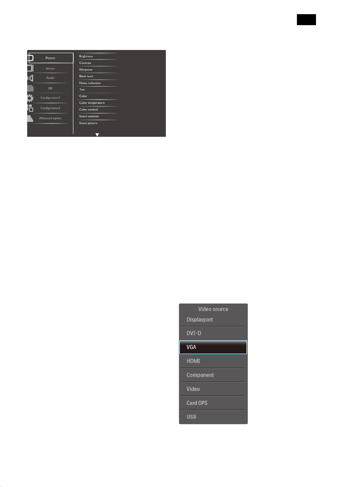
3.4.2 OSD Menu Overview
Picture Menu
Brightness
Adjust the overall image brightness by changing the
intensity of the LCD panel’s backlight.
Contrast
Adjust to sharpen the picture quality. The black
the image.
NOTE: This item is functional for HDMI(Video mode),
Video, and YPbPr inputs only.
Color temperature
Select a color temperature for the image. A lower color
temperature will have a reddish tint, whilst a higher
color temperature gives off a more bluish tint.
Choose from: {3000K} / {4000K} / {5000K} / {6500K} /
{7500K} / {9300K} / {10000K} / {Native} / {User}.
Color control
With this function you can adjust the color tones of the
image precisely by changing the R (Red), G (Green)
and B (Blue) settings independently.
NOTE: This item is functional only when {Color
temperature} is set to {User}.
portions of the picture become richer in darkness and
the white become brighter.
Sharpness
Adjust to improve the image detail.
Black level
Video black level is defined as the level of brightness
at the darkest (black) part of a visual image. Adjust to
change the image brightness.
Noise reduction
Adjust to remove the noise in the image. You can
select a suitable noise reduction level.
Choose from: {Off} / {Low} / {Medium} / {High}.
NOTE: This item is functional for HDMI (Video mode),
Video and YPbPr inputs only.
Tint
Smart contrast
When turned on, this function helps enhance image
contrast when displaying dark scenes.
Smart picture
The following smart picture modes are available for:
PC mode: {Standard} / {Highbright} / {sRGB}.
Video mode: {Standard} / {Highbright} / {Cinema}.
Video source
Select a video input source.
Adjust to change the color tint of the image.
Use the [+] or [-] button to adjust. Press the [+] button
and the flesh tone color turns slightly green. Press the
[-] button and the flesh tone color turns slightly purple.
NOTE: This item is functional for HDMI (Video mode),
Video and YPbPr inputs only.
Color
Adjust to increase or decrease the intensity of colors in
Picture reset
Reset all settings in the Picture menu.
16
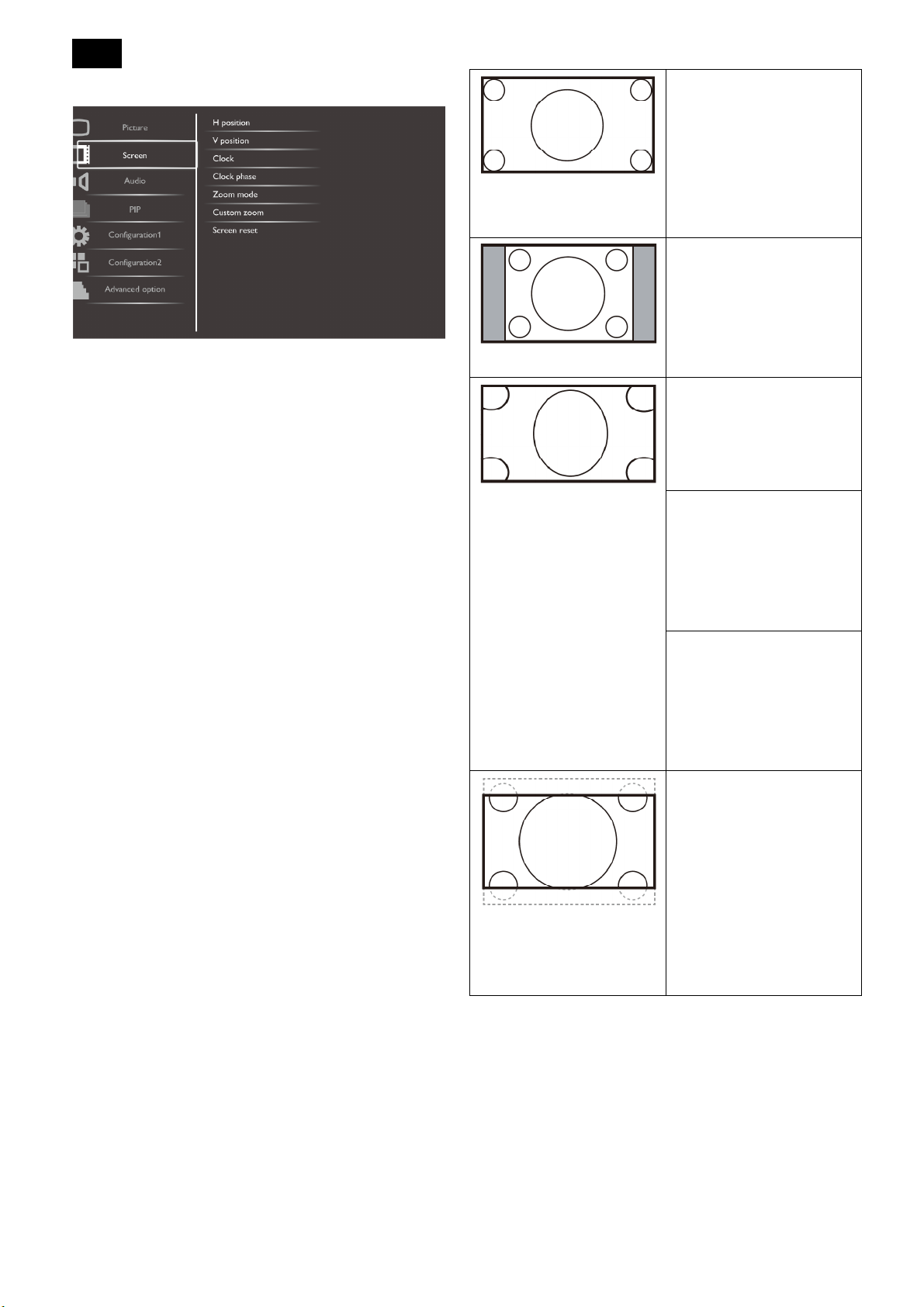
Screen Menu
H position
Press the [+] button to move the image to the right, or
[-] to move the image to the left.
NOTE: This item is functional for all inputs except
HDMI, Card OPS, and DP in video mode.
V position
Press the [+] button to move the image up, or [-] to
move the image down.
NOTE: This item is functional for all inputs except
HDMI, Card OPS, and DP in video mode.
Clock
Adjust the width of the image.
NOTE: This item is functional for VGA input only.
Full
This mode restores the
correct proportions of
pictures transmitted in
16:9 using the full screen
display.
Normal
The picture is reproduced
in 4:3 format and a black
band is displayed on
either side of the picture.
Dynamic
Fill the entire screen by
stretching 4:3 pictures
non-proportionally.
Custom
Choose to apply the
custom zoom settings in
the Custom Zoom
submenu.
Real
This mode displays the
image pixel-by-pixel on
screen without scaling the
Clock phase
Adjust to improve the focus, clarity and stability of the
image.
NOTE: This item is functional for VGA input only.
Zoom mode
The pictures you receive may be transmitted in 16:9
format (wide screen) or 4:3 format (conventional
screen). The 16:9 pictures sometimes have a black
band at the top and bottom of the screen (letterbox
format).
This function allows you to optimize the picture display
on screen. The following zoom modes are available
for:
PC mode: {Full} / {Normal} / {Custom} / {Real}.
Video mode: {Full} / {Normal} / {Dynamic} / {Custom}
/ {Real} / {21:9}.
original image size.
21:9
The picture is enlarged to
16:9 format. This mode is
recommended when
displaying pictures that
have black bands at the
top and bottom (letterbox
format).
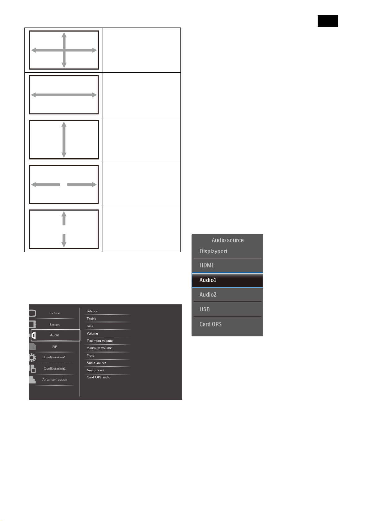
Custom zoom
You can use this function to further customize the
zoom settings to suit the image you want to display.
NOTE: This item is functional only when the Zoom
mode setting is set to Custom.
17
Zoom
Expands the horizontal
and vertical sizes of the
image simultaneously.
H zoom
Expands the horizontal
size of the image only.
V zoom
Expands the vertical size
of the image only.
H position
Moves the horizontal
position of the image left
or right.
Volume
Adjust to increase or decrease the audio output level.
Maximum volume
Adjust your own limitation for the maximum volume
setting. This stops the volume from being playing at
too loud a level.
Minimum volume
Adjust your own limitation for the minimum volume
setting.
Mute
Turn the mute function on/off.
Audio source
Select the audio input source according to the audio
signal source connected to the audio input and HDMI
V position
Moves the vertical
position of the image up
or down.
Screen reset
Reset all settings in the Screen menu to factory preset
values
Audio Menu
sockets on the display.
Choose from: {HDMI} / {Audio1} / {Audio2}.
Audio reset
Reset all settings in the Audio menu to factory preset
values.
Balance
Adjust to emphasize left or right audio output balance.
Treble
Adjust to increase or decrease higher-pitched sounds.
Bass
Adjust to increase or decrease lower-pitched sounds.
18
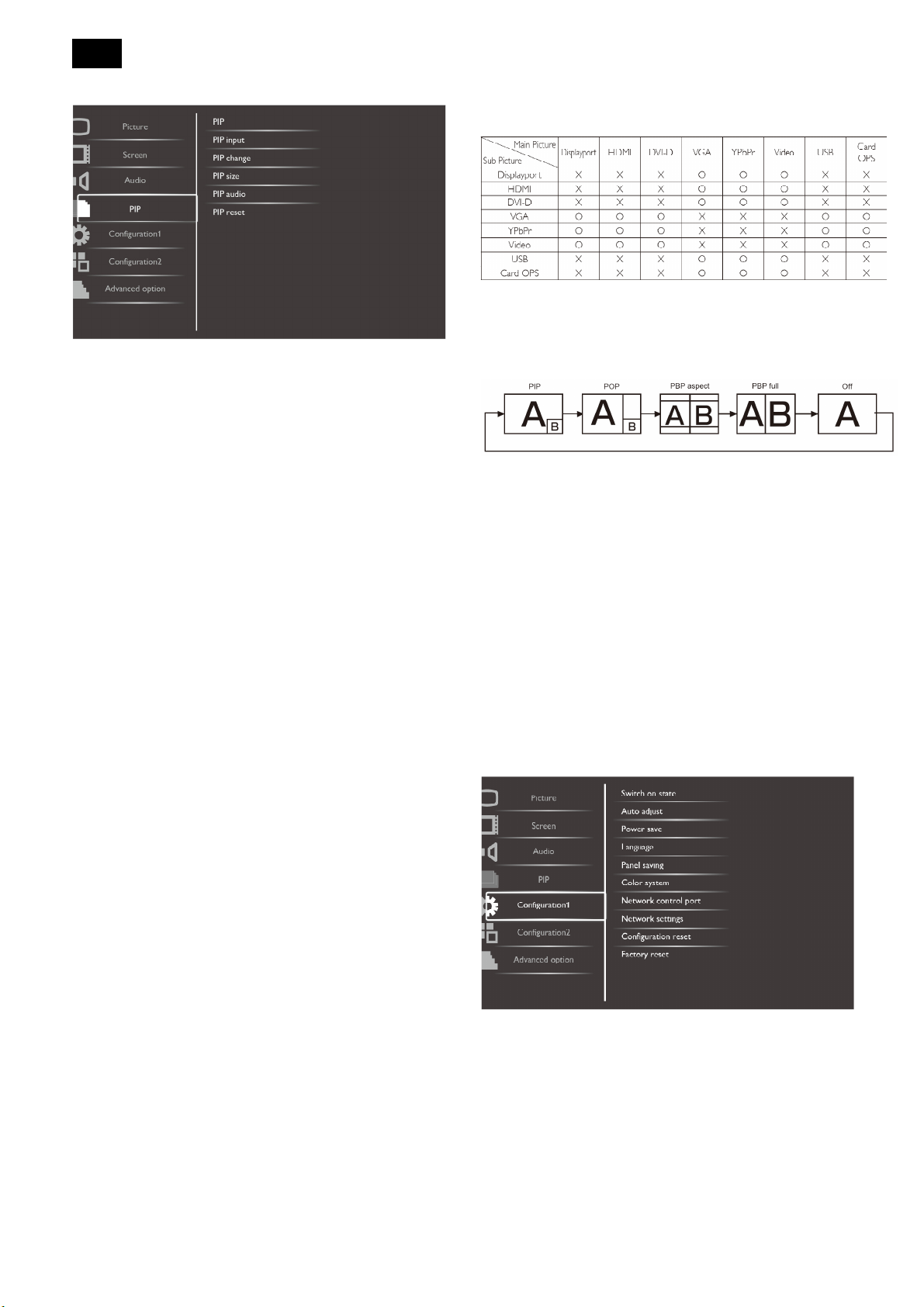
PIP Menu
depend on the resolution of the input signal being
used.
(O: PIP function available, X: PIP function unavailable)
By pressing the [PIP ON/OFF] button on the remote control, you
PIP
Select the PIP (Picture-in-Picture) mode.
Choose from: {Off} / {PIP} / {POP} / {PBP aspect} /
{PBP full}.
PIP input
Select the input signal for the sub-picture.
PIP change
Enlarges the smaller picture to become the main
picture, and vice versa.
PIP size
Select the size of the sub picture in the PIP
(Picture-in-Picture) mode.
Choose from: {Small} / {Medium} / {Large}.
PIP audio
Select the audio source in the PIP (Picture-in-Picture)
can change the mode in the order shown below:
The resolutions in the PIP and POP modes are
configured as follows:
PIP SIZE {Small}: 320 x 240 pixels
{Medium}: 480 x 320 pixels
{Large}: 640 x 480 pixels
POP SIZE: 474 x 355 pixels
NOTE: The images displayed in the sub picture always
fit the PIP sizes shown above irrespective of the
aspect ratio of the input image.
Configuration1 Menu
mode.
• {Main} - Select audio from the main picture
• {Sub} - Select audio from the sub picture.
PIP reset
Reset all settings in the PIP menu to factory preset
values.
NOTES:
• The PIP function is available only for the following
condition: {Configuration1} - {Panel saving} - {Pixel
shift} setting to [Off] and {Advanced option} - {Tiling}
- {Enable} setting to [No].
• The PIP function is available only for certain signal
source combinations as shown in the table below.
• The availability of the PIP function will also
Switch on state
Select the display status used for the next time you
connect the power cord.
{Power off} - The display will remain off when the
power cord is connected to a wall outlet.
{Forced on} - The display will turn on when the
power cord is connected to a wall outlet.
{Last status} - The display will return to the previous
19
power status (on/off/standby) when removing and
replacing the power cord.
Auto Adjust
Use this function to automatically optimize the display
of VGA input image.
NOTE: This item is functional for VGA input only.
Power Save
Use this setting to reduce the power automatically.
{RGB} - Select {On} to let the display enter APM
mode when no signal detected from the HDMI
Graphic mode, HDMI, DVI-D, or VGA inputs after
three successive cycles.
{VIDEO} - Select {On} to enter power saving mode
when no signal is detected from the HDMI Video
mode or YPbPr inputs after three successive
cycles.
{Brightness} - Select {On} and the image brightness
will be reduced to an appropriate level. The
Brightness setting in the Picture menu will be
unavailable when selected.
{Pixel shift} - Select the time interval ({Auto} / {10 ~
900} Seconds / {Off}) for the display to slightly
expand the image size and shift the position of
pixels in four directions (up, down, left, or right).
Color system
Selects the Color System depending on your input
video format.
The options are: {Auto} / {NTSC} / {PAL} / {SECAM} /
{4.43NTSC} / {PAL-60}.
NOTE: This item is functional for VIDEO input only.
Network control port
Select the network control port.
Language
Select the language used in the OSD menu.
The options are: {English} / {Deutsch} / {中文} /
{Français} / {Italiano} / {Español} / {Pyccĸий} / {Polski} /
{Türĸçe}.
Panel saving
Choose to enable the panel saving functions and thus
reduce the risk of the “image persistence” or
“ghost-imaging”.
{Cooling Fan} - Select {On} to turn on the cooling
fan all the time. Select {Auto} to turn on/off the
cooling fan according to the display’s temperature.
NOTES:
- The default {Auto} option will start running the
cooling fan if the temperature of 65°C (152°F) is
reached, and will keep running for 30 minutes
Choose from: {RS232} / {LAN (RJ45)} /{Card OPS
RS232}.
NOTE:
• If {LAN (RJ45)} is selected, then {RS232} will not be
activated, even if a cable is attached, and vice versa.
• The option {Card OPS RS232} is functional after
connected with your OPS device.
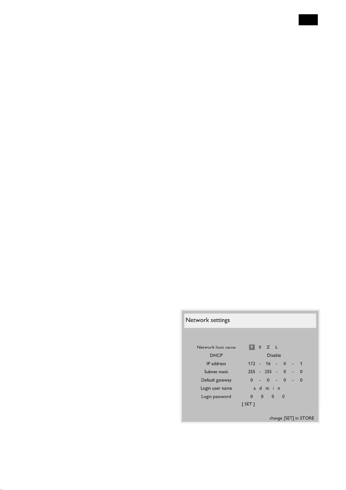
Network settings
Assign {IP address}, {Subnet Mask}, and {Default
gateway} for the display.
after cooling down to the temperature of 62°C
(144°F).
- A temperature-warning message will be shown
on the screen if the temperature reaches 79°C
(174°F). All key function except [Power] key will
then be disabled.
- Once the temperature reaches 80°C (176°F), the
display power will be shut down automatically.
DHCP - Choose to enable or disable the DHCP
function. If enabled, the display will be assigned IP
address, Subnet mask and Default gateway
automatically. If disabled, you will be prompted to
20
enter the following value manually. When finished,
press [SET] button to store and save the chosen
values.
IP address
Subnet mask
Default gateway
Login user name (The default user name is {admin})
Login password (The default password is {0000})
Configuration2 Menu
Configuration reset
Reset all settings in the Configuration1 menu to factory
preset values.
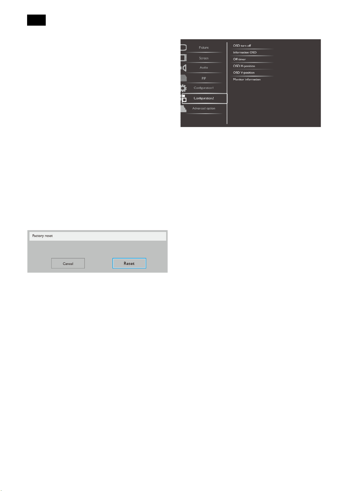
Factory reset
Reset all the settings in the OSD menus of {Picture},
{Screen}, {Audio}, {PIP}, {Configuration1},
{Configuration2}, and {Advanced option} to factory
preset values.
Press [+] or [-] button to select [Reset], and then press
[SET] button to do the reset
.
OSD turn off
Set the period of time the OSD(on-screen display)
menu stays on the screen.
The options are: {5 ~ 120} seconds.
Information OSD
Set the period of time the information OSD displayed
on the upper right corner of the screen. The
information OSD will display when input signal is
changed.
The information OSD will remain on the screen with
{Off} selection.
The options are: {1 ~ 60} seconds.
Off Timer
Set the display to turn itself off to standby mode within
an amount of time specified.
The options are: {off, 1 ~ 24} hours from current time.
NOTE: When the “Off timer” is activated, the
“Schedule” settings will be disabled.
OSD H-position
Adjust the horizontal position of the OSD menu.
OSD V-position
Adjust the vertical position of the OSD menu.
Monitor information
Shows information about your display, including model
number, serial number, operating hours and software
version.
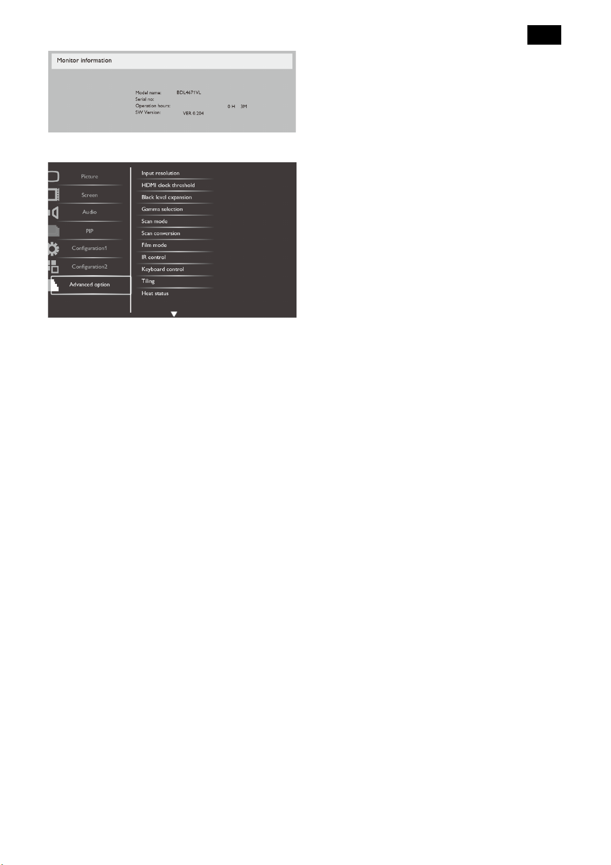
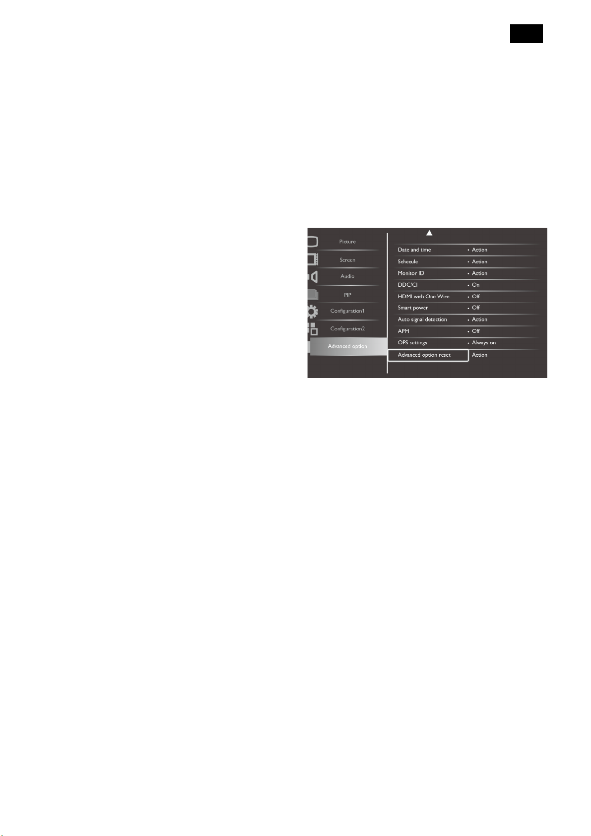
Advanced Option Menu
Input resolution
Set the resolution of the VGA input. This is only
required when the display is unable to detect the VGA
input resolution correctly.
NOTE: This item is functional for VGA input only.
The options are:
{1024x768 / 1280x768 / 1360x768 / 1366x768}
{1400x1050 / 1680x1050}
appear too white or too dark, so controlling the gamma
properly can have a huge influence on the overall
picture quality of your display.
The options are: {Native} / {2.2} / {2.4} / {S gamma}.
Scan mode
Change the display area of the image.
{Overscan} - Display about 95% of the original size
of the image. The rest of the areas surrounding the
image will be cut off.
{Underscan} - Display the image in its original size.
NOTE: This item is functional for Video mode input
only.
Scan conversion
Choose to enable or disable the IP (Interlace to
Progressive) conversion function.
{Progressive} - Enable the IP conversion function
(recommended). Once enabled, the interlace input
signal will be converted to progressive format for
better display quality.
{Interlace} - Disable the IP function. This mode is
suitable for displaying motion pictures, but it
increases the chance of image retention.
21
{1600x1200 / 1920x1200}
{Auto}: Determines the resolution automatically.
The selected settings will become effective after
turning off the power and turn it on again.
HDMI clock threshold
Adjust HDMI link clock.
• {Min} - 800KHz.(Default)
• {Max} - 5000KHz.
Black level expansion
This feature offers deeper blacks for an even better
image quality.
The options are: {Off} / {Low} / {Medium} / {High}.
NOTE: This item is functional for Video mode inputs
only.
Gamma selection
Gamma is what controls the overall brightness of an
image. Images which are not corrected properly can
Film mode
Choose to turn on or off the film mode frame
conversion function.
{Auto} - Enable the film mode frame conversion
function for movies and motion pictures. The display
converts a 24 frames-per-second (24 fps) input
signal format to DVD video signal format. Once this
function is enabled, it is recommended that you set
the {Scan conversion} function to {Progressive}.
{Off} - Disable the film mode frame conversion
function. This mode is suitable for TV broadcasting
and VCR signals.
IR control
Select the operation mode of the remote control when
multiple displays are connected via the RS232C
connection.
{Normal} - All displays can be operated normally by
the remote control unit.
22
{Primary} - Designate this display as the primary
display for remote control operation. Only this
display can be operated by the remote control.
{Secondary} - Designate this display as the
secondary display. This display cannot be operated
by the remote control, and will only receive the
control signal from the primary display via the
RS232C connection.
{Lock all} / {Lock all but Volume} / {Lock all but
Power} - Lock the remote control function of this
display. To unlock, press and hold the [DISPLAY]
button on the remote control for 5 (five) seconds.
Keyboard control
Choose to enable or disable the display keyboard
(control buttons) function.
{Unlock} - Enable the keyboard function.
{Lock All} / {Lock all but Volume} / {Lock all but
Power} - Disable the keyboard function.
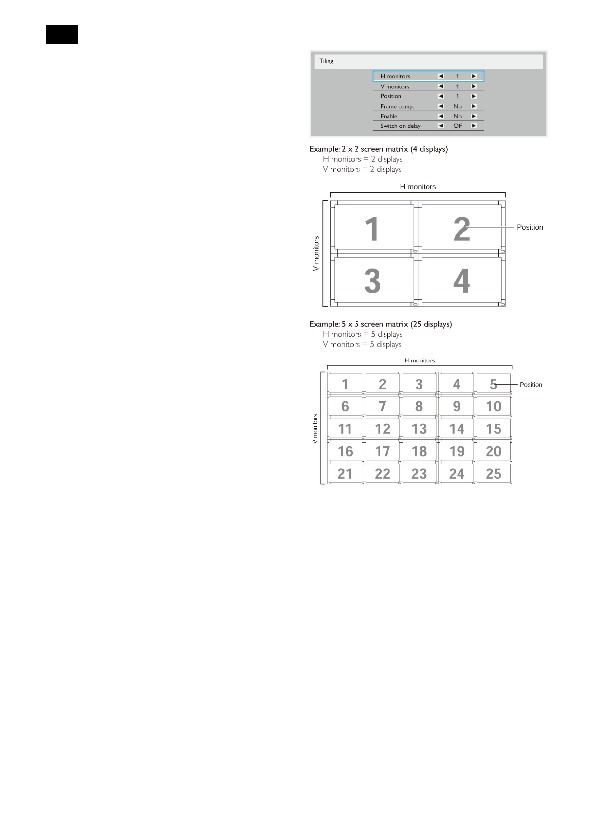
Tiling
With this function you can create a single large-screen
matrix (video wall) that consists of up to 25 sets of this
display (up to 5-set each on the vertical and horizontal
side). This function requires a daisy-chain connection.
H monitors - Select the number of displays on the
horizontal side.
V monitors - Select the number of displays on the
vertical side.
Position - Select the position of this display in the
screen matrix.
Frame comp. - Choose to turn the frame
compensation function on or off. If selected {Yes},
the display will adjust the image to compensate for
the width of the display bezels in order to accurately
display the image.
Frame comp. – on
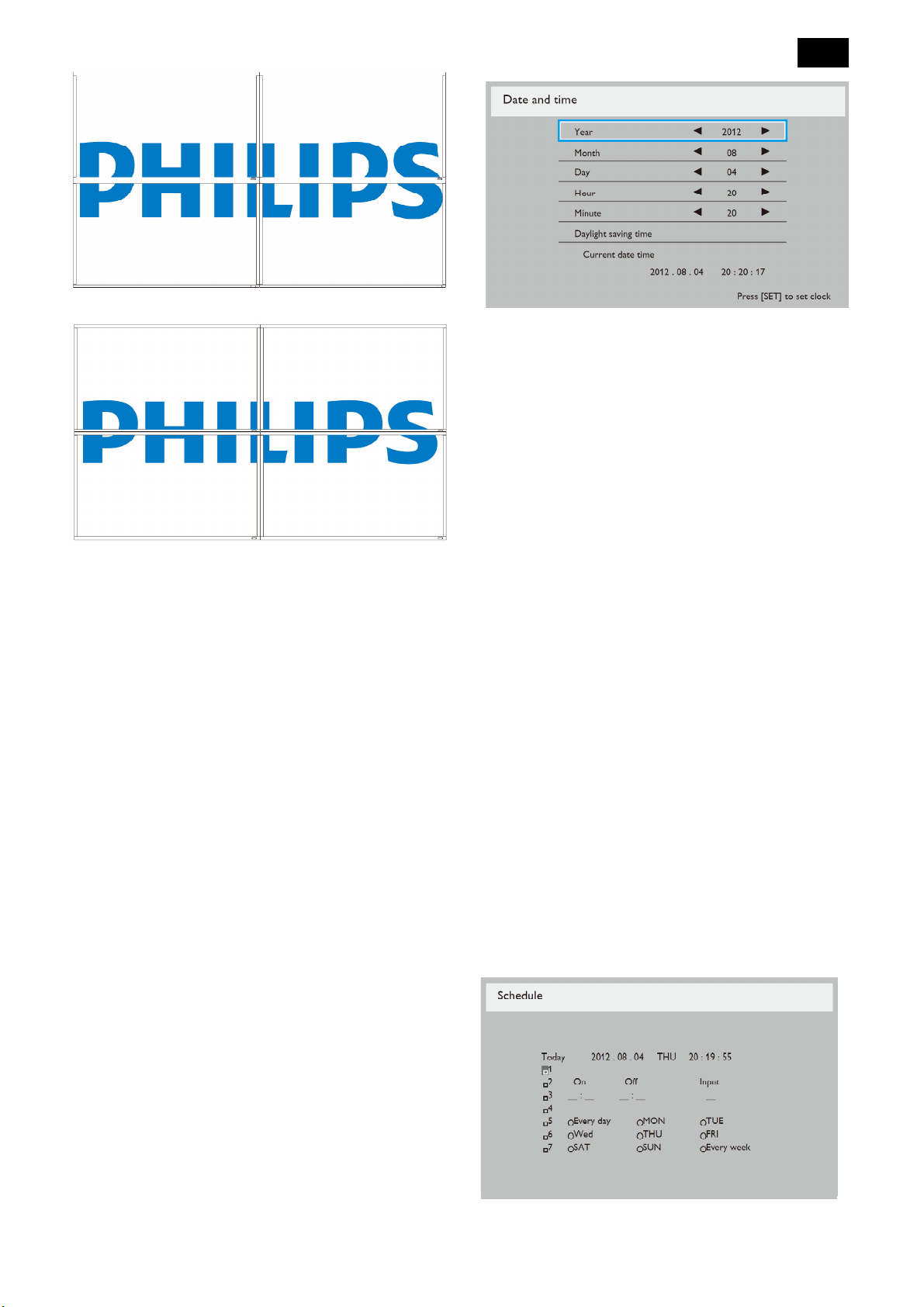
Frame comp. – off
23
1. Press [+] button to enter the submenu.
2. Press [▲] or [▼] button to toggle among the {Year},
{Month}, {Day}, {Hour}, {Minute}, and {Daylight
saving time}.
3. Press [+] or [-] button to adjust all settings except
{Daylight saving time}.
4. Press [SET] button to enter the {Daylight saving}
Enable: Choose to enable or disable the Tiling
function. If enabled, the display will apply the
settings in {H monitors}, {V monitors}, {Position}, and
{Frame comp.}.
Switch on delay: Set the power-on delaying time (in
seconds). The default option {Auto} allows a
sequential powering-on for each display by their ID
number when multiple displays are connected. The
options are: {off / Auto / 2, 4, 6, 8, 10, 20, 30, 40, 50}
NOTE: The Tiling function will be disabled when the
[ON/OFF] button for PIP is pressed.
Heat status
This function allows you to check the thermal status of
the display at any time.
Date and time
submenu.
5. Press [+] or [-] button to select item, press [▲] or
[▼] button to adjust.
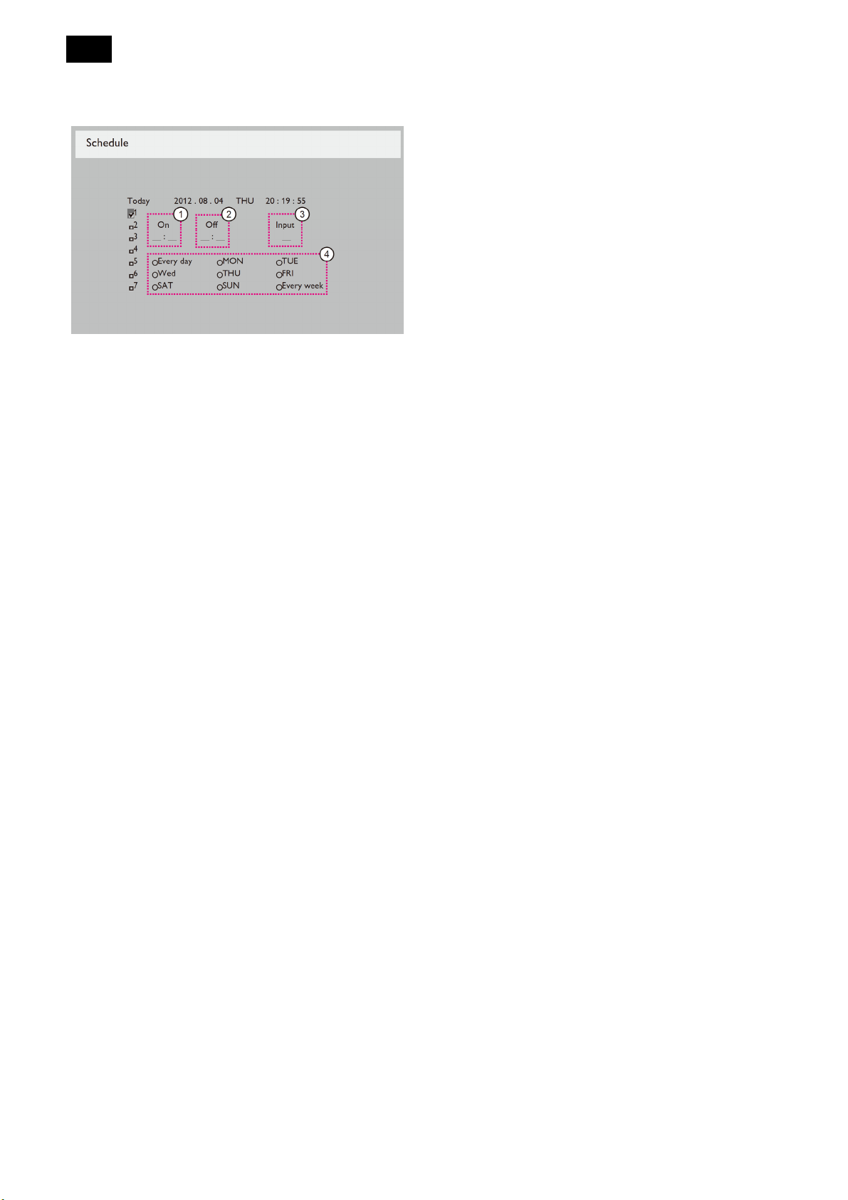
Schedule
This function allows you to program up to 7 (seven)
different scheduled time intervals for the display to
activate.
You can select:
The time for the display to turn on and turn off.
The days in a week for the display to activate.
Which input source the display will use for each
scheduled activation period.
NOTE: We recommend you to set up current date and
time in {Date and time} menu before using this
function.
1. Press [SET] or [+] button to enter the submenu.
Adjust the current date and time for the display’s
internal clock.
2. Press [▲] or [▼] button to select a schedule item
24
(item number 1 ~ 7), and then press [+] button to
Monitor ID
mark it the item number.
3. Press [+] or [-] button to select the schedule:
1) Power-on schedule: Press [▲] or [▼] button to
set the hour and minute for the display to turn on.
2) Power-off schedule: Press [▲] or [▼] button to
set the hour and minute for the display to turn off.
Select or leave an empty “__” for both the hour and
minute slot if you do not want to use this power-on
Set the ID number for controlling the display via the
RS232C connection. Each display must have a unique
ID number when multiple sets of this display are
connected.
DDC/CI
Choose to turn on or off the DDC/CI communication
function. Select {On} for normal use.
HDMI with One Wire
CEC control.
• {Off} - Disable CEC.(Default)
• {On} - Enable CEC.
Smart power
Set the display to reduce the power consumption
automatically.
The options are: {Off} / {Medium} / {High}.
or power-off schedule.
3) Input-source selection: Press [▲] or [▼] button to
select an input source. If no input source is
selected, the input source will remain the same as
last selected.
4) Date schedule: Press [+] button to select which
day in a week this schedule item will be take
effect, and then press the [SET] button.
4. For additional schedule settings, press [EXIT], then
repeat the steps above. A check mark in the box
next to the number of the schedule item indicates
that the selected schedule is in effect.
NOTES:
The {Every day} selection in a schedule item takes
priority over the other weekly schedules.
If the schedule overlaps, the scheduled power-on
time takes priority over scheduled power-off time.
If there are two schedule items programmed for the
same time, the highest numbered schedule takes
Auto signal detection
Choose to let the display detect and display available
signal sources automatically.
• {Off} - Once a signal is connected, it can only be
selected manually.
No signal, set the display to display the image
automatically according to the search order of each
option.
The options are: {All} / {All except USB} / {PC source
only} / {Video source only} / {Failover}
• {All} - Search order: DP -> DVI-> VGA -> HDMI ->
Component-> Video -> Card OPS -> USB.
• {All except USB} - Search order: DP -> DVI -> VGA ->
HDMI -> Component -> Video -> Card OPS.
• {PC source only} - Search order: DP -> DVI -> VGA ->
HDMI -> Card OPS -> USB
• {Video source only} - Search order: HDMI ->
Component -> Video
priority. For example, if schedule items #1 and #2
both set the display to power on at 7:00 AM and off
at 5:00 PM, then only schedule item # 1 will take
effect.
• {Failover} - Primary input(selected by user), default is
HDMI. Secondary input(selected by user), default is
USB.
NOTE:
25
• The primary input signal to display priority, and this
item is functional for Primary input signal only.
• Auto search is functional for No signal only. If the
user set the input source manually, the display is
based on the users set priority
APM
Power save setting.
{Off} - No signal, direct shutdown. ( Default )
{On} - No signal, enter into Power Save mode.
OPS settings
Set the OPS configuration under each power
condition.
{Auto} - After selecting {Card OPS} for video source
input, the OPS will be set to off when the display
power is set to off, or set to on when the display
Advanced option reset
Reset all settings in the Advanced option menu to
factory preset values.
1. Press [SET] or [+] button to enter the submenu.
2. Press [+] or [-] button to select {Reset} and press
the [SET] button to restore settings to factory preset
values.
3. Press the [EXIT] button or select {Cancel} and press
the [SET] button to cancel and then return to the
previous menu.
power is set to on. When set to other video source
inputs, the OPS will always be set to on.
{Always off} - The OPS will always be set to off.
{Always on} - The OPS will always be set to on.
26
4. Input/ Output Specification
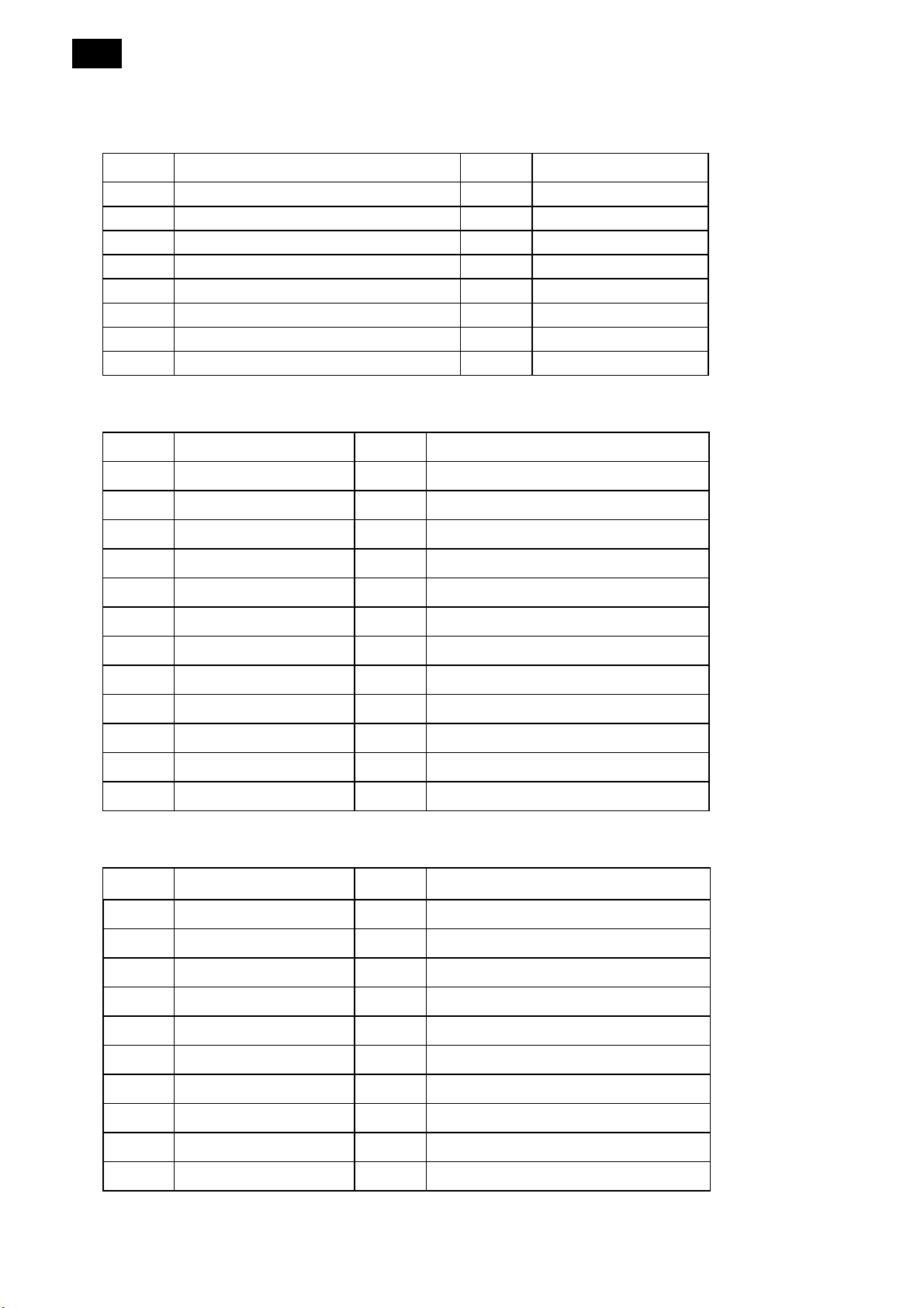
4.1 Input Signal Connector
1. VGA
Pin No. Name Pin No. Name
1 Red video 2 Green video
3 Blue video 4 GND
5 GND 6 Red GND
7 Green GND 8 Blue GND
9 +5V (Supply from PC for DDC circuit) 10 Sync GND
11 GND 12 DDC serial data
13 H-sync 14 V-sync
15 DDC serial clock
2. DVI-D Input
Pin No. Name Pin No. Name
1 TMDS Data2- 2 TMDS Data2+
3 TMDS Data2/4 Shield 4 N/A
5 N/A 6 DDC clock
7 DDC data 8 N/A
9 TMDS Data1- 10 TMDS Data1+
11 TMDS Data1/3 Shield 12 N/A
13 N/A 14 +5V
15 GND 16 Hot plug
17 TMDS Data0- 18 TMDS Data0+
19 TMDS Data0/5 Shield 20 N/A
21 N/A 22 TMDS clock shield
23 TMDS clock+ 24 TMDS clock-
3. HDMI Input
Pin No. Name Pin No. Name
1 TMDS Data2+ 2 TMDS Data2 Shield
3 TMDS Data2– 4 TMDS Data1+
5 TMDS Data1 Shield 6 TMDS Data1–
7 TMDS Data0+ 8 TMDS Data0 Shield
9 TMDS Data0– 10 TMDS Clock+
11 TMDS Clock Shield 12 TMDS Clock–
13 CEC 14 Reserved (N.C. on device)
15 SCL 16 SDA
17 DDC/CEC Ground 18 +5V Power
19 Hot Plug Detect
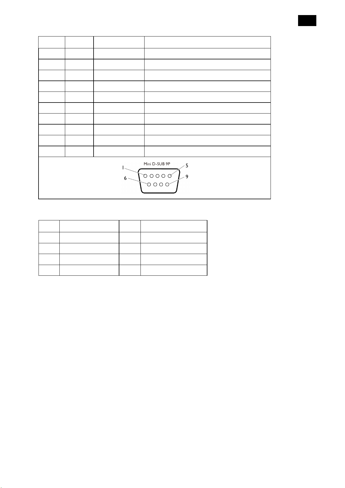
4. RS-232C Input /Output
DB-25 D-sub-9 Signal Direction Signal Name
1 x Protective Ground
2 3 DTE-to-DCE Transmitted Data
3 2 DCE-to-DTE Received Data
4 7 DTE-to-DCE Request To Send
5 8 DCE-to-DTE Clear To Send
6 6 DCE-to-DTE Data Set Ready
7 5 x Signal Ground
8 1 DCE-to-DTE Received Line Signal Detector (Carrier Detect)
20 4 DTE-to-DCE Data Terminal Ready
22 9 DCE-to-DTE Ring Indicator
27
5. RJ-45 Input
Pin Signal Assignment Pin Signal Assignment
1 Transmit+ 2 Transmit-
3 Receive+ 4 N/A
5 N/A 6 Receiver–
7 N/A 8 N/A
28
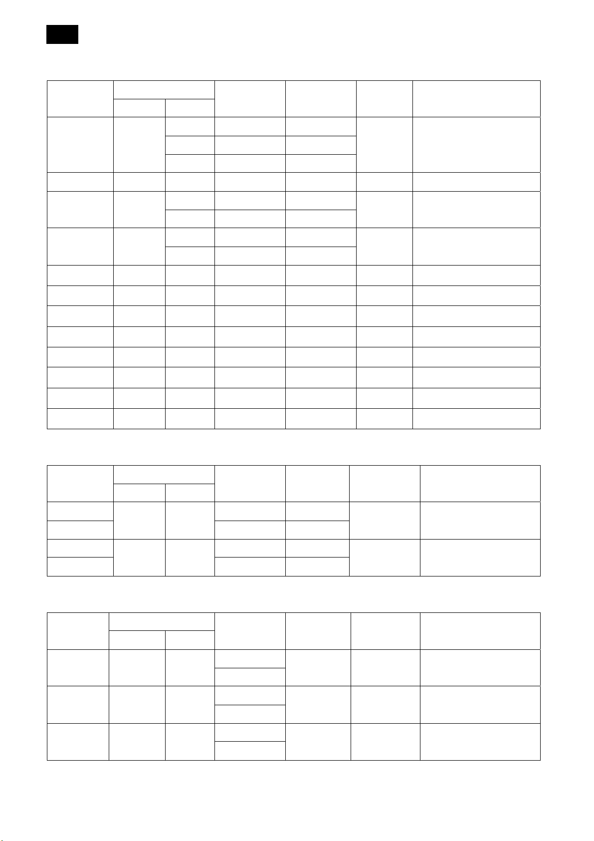
4.2 Factory Preset Modes
VGA Resolution:
Standard
Resolution
VGA 640
WVGA 720 400 70 Hz 33.75 MHz 16:9 Wide Video Graphic Array
SVGA 800
XGA 1024
WXGA 1280 768 60 Hz 79.5 MHz 5:3 Wide XGA
WXGA 1280 800 60 Hz 79.5 MHz 16:10 Wide XGA
SXGA 1280 960 60 Hz 108 MHz 4:3 Super XGA
SXGA 1280 1024 60 Hz 108 MHz 5:4 Super XGA
WXGA 1360 768 60 Hz 85.5 MHz 16:9 Wide XGA
WXGA 1366 768 60 Hz 85.5 MHz 16:9 Wide XGA
Active Resolution
H pixels V Lines
480 60 Hz 25.175MHz
75Hz 75 Hz 31.5 MHz
600 60 Hz 40 MHz
75 Hz 75 Hz 49.5 MHz
768 60 Hz 65MHz
75 Hz 75 Hz 78.75 MHz
Refresh Rate
(Hz)
Pixel Rate
(MHz)
Aspect
Stand for Mode
Ratio
4:3 Video Graphic Array 72Hz 72 Hz 31.5 MHz
4:3 Super VGA
4:3 Extend Graphic Array
UXGA 1600 1200 60 Hz 162 MHz 4:3 Ultra XGA
HD1080 1920 1080 60 Hz 148.5 MHz 16:9 HD1080
SDTV Resolution:
Standard
Resolution
480i
480p 59.94 Hz 27 MHz
576i
576p 50 Hz 27 MHz
HDTV Resolution
Standard
Resolution
720p 1280 720
Active Resolution
H pixels V Lines
720 480
720 480
Active Resolution
H pixels V Lines
Refresh Rate Pixel Rate Aspect Ratio Stand for Mode
29.97 Hz 13.5 MHz
4:3
25 Hz 13.5 MHz
4:3 Modified PAL Standard
Refresh Rate Pixel Rate Aspect Ratio Stand for Mode
50 Hz
74.25 MHz 16:9 Normally DVB Mode
60 Hz
Modified NTSC
Standard
1080i 1920 1080
1080p 1920 1080
25 Hz
74.25 MHz 16:9 Normally ATSC Mode
30 Hz
50 Hz
148.5 MHz 16:9 Normally ATSC Mode
60 Hz
• The PC text quality is optimum in HD 1080 mode (1920 x 1080, 60Hz).
• Your PC display screen might appear different depending on the manufacturer (and your particular version of
Windows).
• Check your PC instruction book for information about connecting your PC to a display.
• If a vertical and horizontal frequency-select mode exists, select 60Hz (vertical) and 31.5KHz (horizontal). In some
cases, abnormal signals (such as stripes) might appear on the screen when the PC power is turned off (or if the
PC is disconnected). If so, press the [INPUT] button to enter the video mode. Also, make sure that the PC is
connected.
• When horizontal synchronous signals seem irregular in RGB mode, check PC power saving mode or cable
connections.
• The display settings table complies to the IBM/VESA standards, and based on the analog input.
• The DVI support mode is regarded as same to the PC support mode.
• The best timing for the vertical frequency to each mode is 60Hz.
29
4.3 Pixel Defect Policy
We strive to deliver the highest quality products and use some of the industry’s most advanced manufacturing
processes whilst practicing stringent quality control. However, pixel or sub-pixel defects on the PDP / TFT panels
used in Plasma- & LCD- displays are sometimes unavoidable. No manufacturer can guarantee that all panels will
be free from pixel defects, but Philips guarantees that any Plasma- & LCD- displays with an unacceptable number
of defects will be repaired during the warranty period in line with your local guarantee conditions.
This notice explains the different types of pixel defects and defines the acceptable defect level for the LCD screen.
In order to qualify for repair under warranty, the number of pixel defects must exceed a certain level as shown in
the reference table. If the LCD screen is within specification a warranty exchange / claim back will be refused.
Additionally, because some types or combinations of pixel defects are more noticeable than others, Philips sets
even higher quality standards for those.
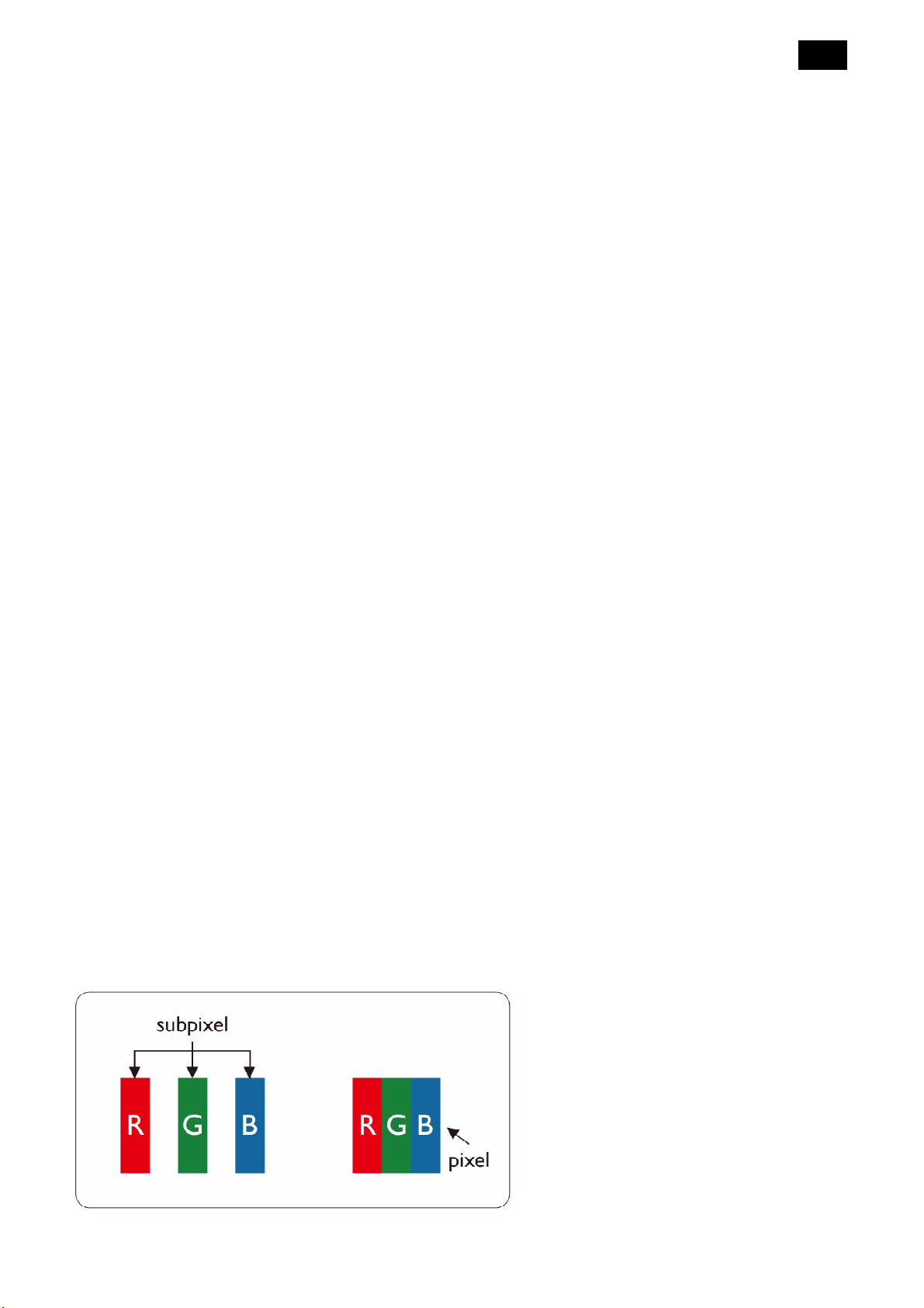
Pixels and Sub-pixels
A pixel, or picture element, is composed of three sub-pixels in the primary colors of red, green and blue. Many
pixels together form an image. When all sub-pixels of a pixel are lit, the three colored sub-pixels together appear as
a single white pixel. When all are dark, the three colored sub-pixels together appear as a single black pixel. Other
combinations of lit and dark sub-pixels appear as single pixels of other colors.
30
Types of Pixel Defects + Dot Definition
Pixel and sub-pixel defects appear on the screen in different ways. There are three categories of pixel defects and
several types of sub-pixel defects within each category.
Dot definition = What is a defective “Dot”?
One or more defective, adjacent sub-pixel is defined as one “dot”. The no. of defective sub-pixels is not relevant to
define a defective dot. This means that a defective dot can consist of one, two or three defective sub-pixels which
can be dark or lit.
One dot = one pixel; consists of three sub-pixel of Red, Green, and Blue.
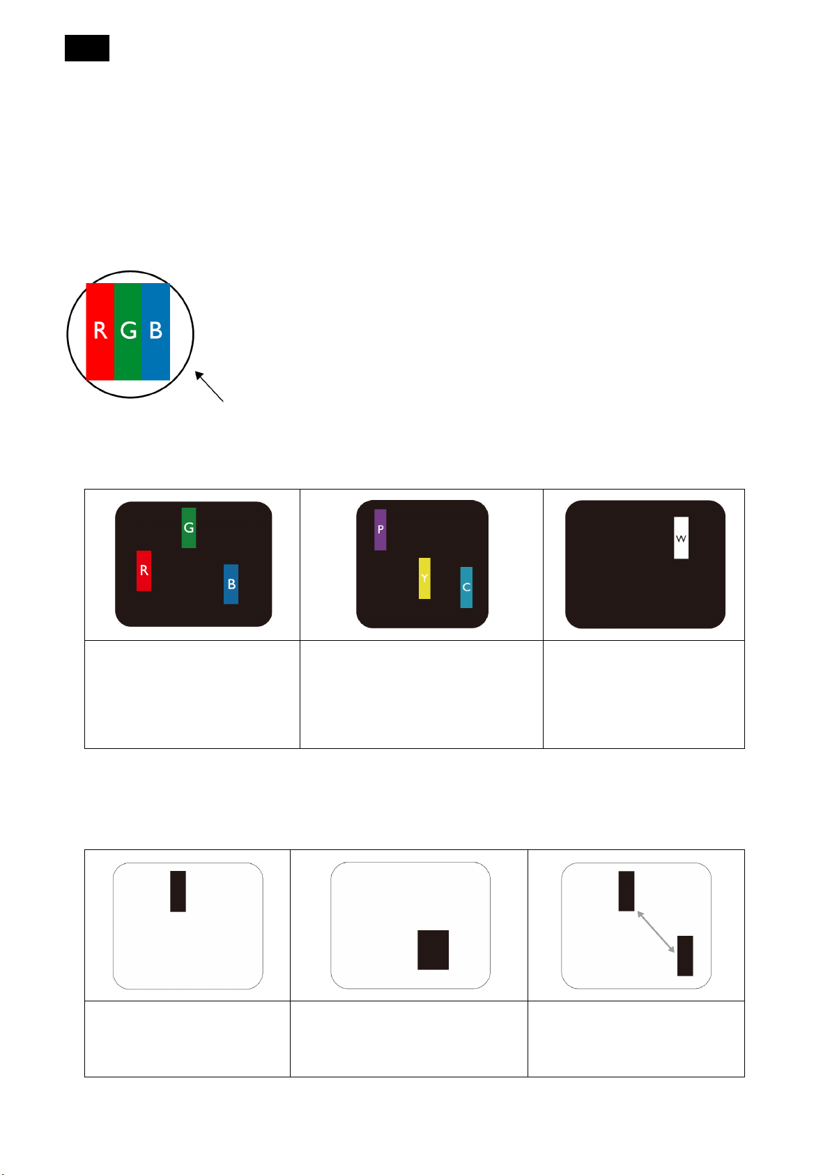
Bright Dot Defects
Bright dot defects appear as pixels or sub pixels that are always lit or ‘on’. There are the examples of bright dot
defects:
One lit red, green or blue sub
pixel
Dark Dot Defects
Two adjacent lit sub-pixels:
- Red + Blue = Purple
- Red + Green = Yellow
- Green + Blue = Cyan (Light Blue)
Three adjacent lit sub-pixels
(one white dot)
Black dot defects appear as pixels or sub-pixels that are always dark or ‘off’. There are the examples of black dot
defects:
One dark dot Two adjacent dark dots =
1 pair of dark dots
Two dark dots, specifications
defines the minimum distance
between dark dots
 Loading...