

Page 1
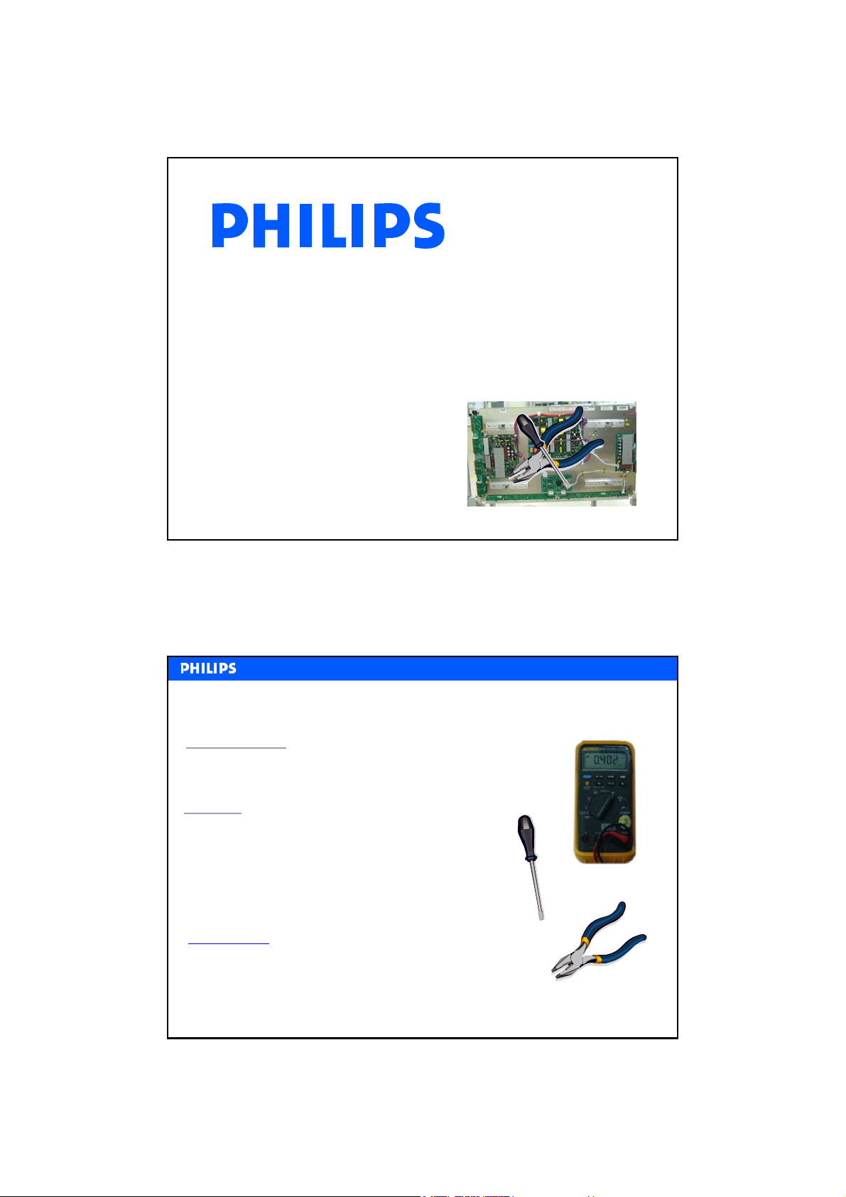
Service Training
Service Training
BASICS of PDP Trouble shooting
L. van der Niet
Philips CE / Euroservice
PDP repair part 2
March 2007
Basics of PDP Trouble shooting ––
Basics of PDP Trouble shooting
Target Audience
Target Audience
This module is intended for Service Engineers
This module is intended for Service Engineers
repairing Plasma Television.
repairing Plasma Television.
Objective
Objective
This module provides a basic knowledge on how to
This module provides a basic knowledge on how to
diagnose and trouble shoot Plasma Display panels
diagnose and trouble shoot Plasma Display panels
in general. It is not model specific. This knowledge
in general. It is not model specific. This knowledge
enables the learner to better recognize major fault
enables the learner to better recognize major fault
symptoms of PDP’s and to identify the parts that
symptoms of PDP’s and to identify the parts that
most probably cause the problem.
most probably cause the problem.
Prerequisites
Students should have an understanding of
the Basics of Television and finished the
module PDP Basics.
Philips CE / Euroservice, L. van der Niet, March 2007, AX67-M07-0026
An Introduction
An Introduction
2
1
Page 2
MAIN
MAIN
TOPICS
TOPICS
Screen faults and other symptoms
PCB functions and waveforms
Suggested repair actions
Philips CE / Euroservice, L. van der Niet, March 2007, AX67-M07-0026
INTRODUCTION
INTRODUCTION
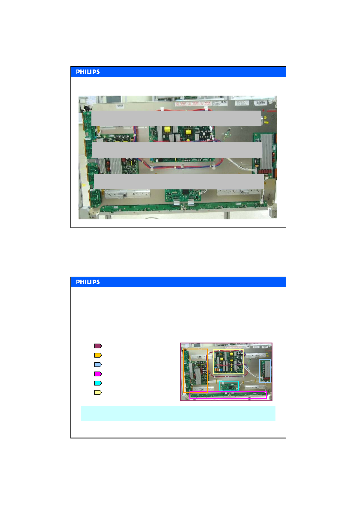
Trouble shooting on the PLASMA DISPLAY Panel is done on board
level. This training module shows a number of common faults that can
be encountered in all PDP Televisions.
Plasma panel faults
Scan & Sustain board faults
Common & Sustain board
Address driver board faults
Control Logic board faults
Power Supply Unit
3
More product specific faults are treated in separate service training modules.
Philips CE / Euroservice, L. van der Niet, March 2007, AX67-M07-0026
4
2
Page 3
Panel Error Examples and Solutions
Panel Error Examples and Solutions
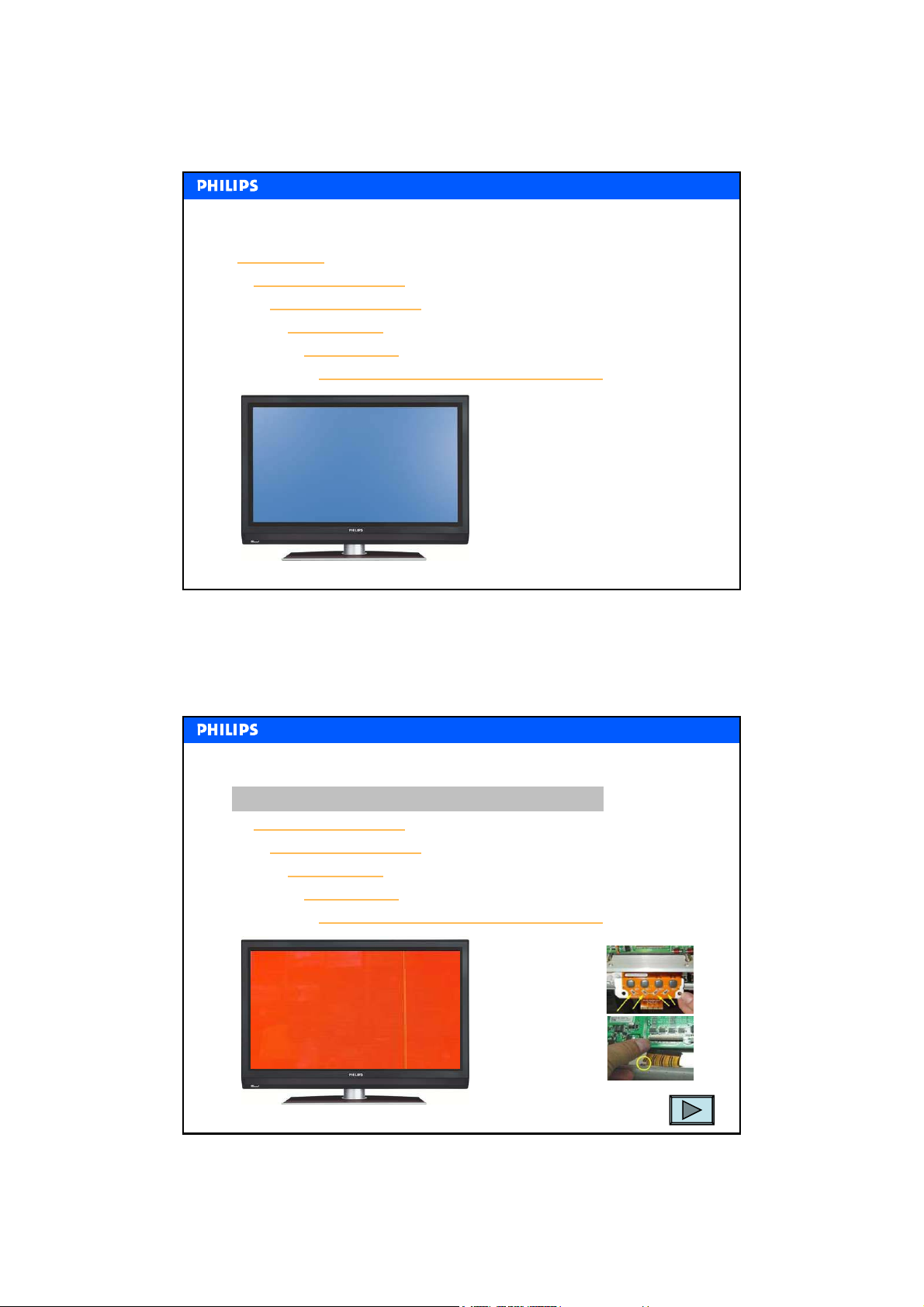
Vertical line
Vertical black bar (1)
Vertical black bar (2)
Vertical lines
Flicker noise
Image retention, but no image sticking
Philips CE / Euroservice, L. van der Niet, March 2007, AX67-M07-0026
Panel Error Examples and Solutions
Panel Error Examples and Solutions
Vertical line
Vertical black bar (1)
Vertical black bar (2)
Vertical lines
Flicker noise
Image retention, but no image sticking
Check the COF
1.Inspect 10 ohm
resistors and
drive IC’s
2.Inspect the film
where the COF
connects to the
Address drive
board
5
3.Replace the Plasma panel
Philips CE / Euroservice, L. van der Niet, March 2007, AX67-M07-0026
6
3
Page 4
Panel Error Examples and Solutions
Panel Error Examples and Solutions
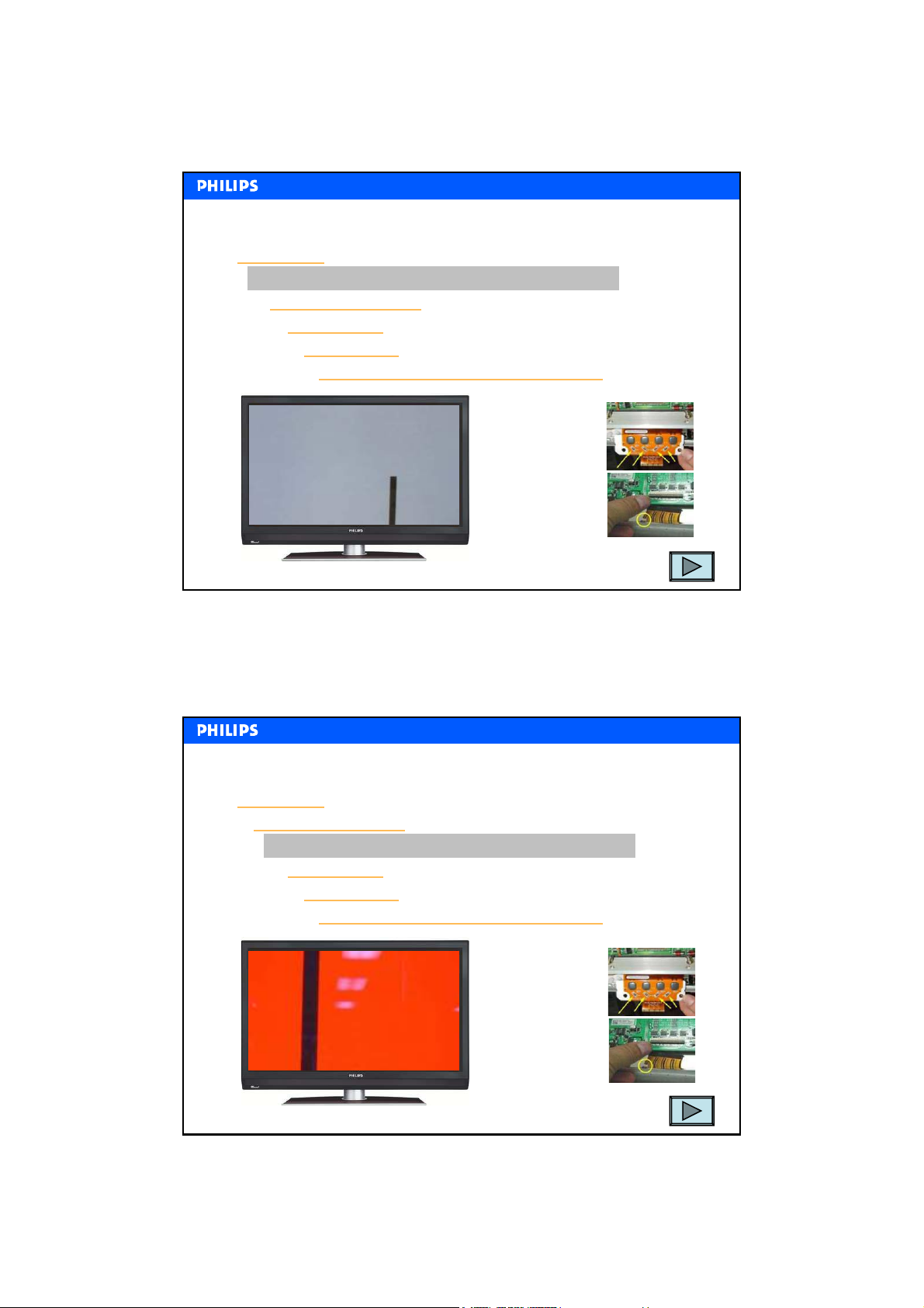
Vertical line
Vertical black bar (1)
Vertical black bar (2)
Vertical lines
Flicker noise
Image retention, but no image sticking
Check the COF
1.Inspect 10 ohm
resistors and
drive IC’s
2.Inspect the film
where the COF
connects to the
Address drive
board
3.Replace the Plasma panel
Philips CE / Euroservice, L. van der Niet, March 2007, AX67-M07-0026
7
Panel Error Examples and Solutions
Panel Error Examples and Solutions
Vertical line
Vertical black bar (1)
Vertical black bar (2)
Vertical lines
Flicker noise
Image retention, but no image sticking
Check the COF
1.Inspect 10 ohm
resistors and drive
IC’s
2.Inspect the film
where the COF
connects to the
Address drive board
3.Replace the Plasma panel
Philips CE / Euroservice, L. van der Niet, March 2007, AX67-M07-0026
8
4
Page 5
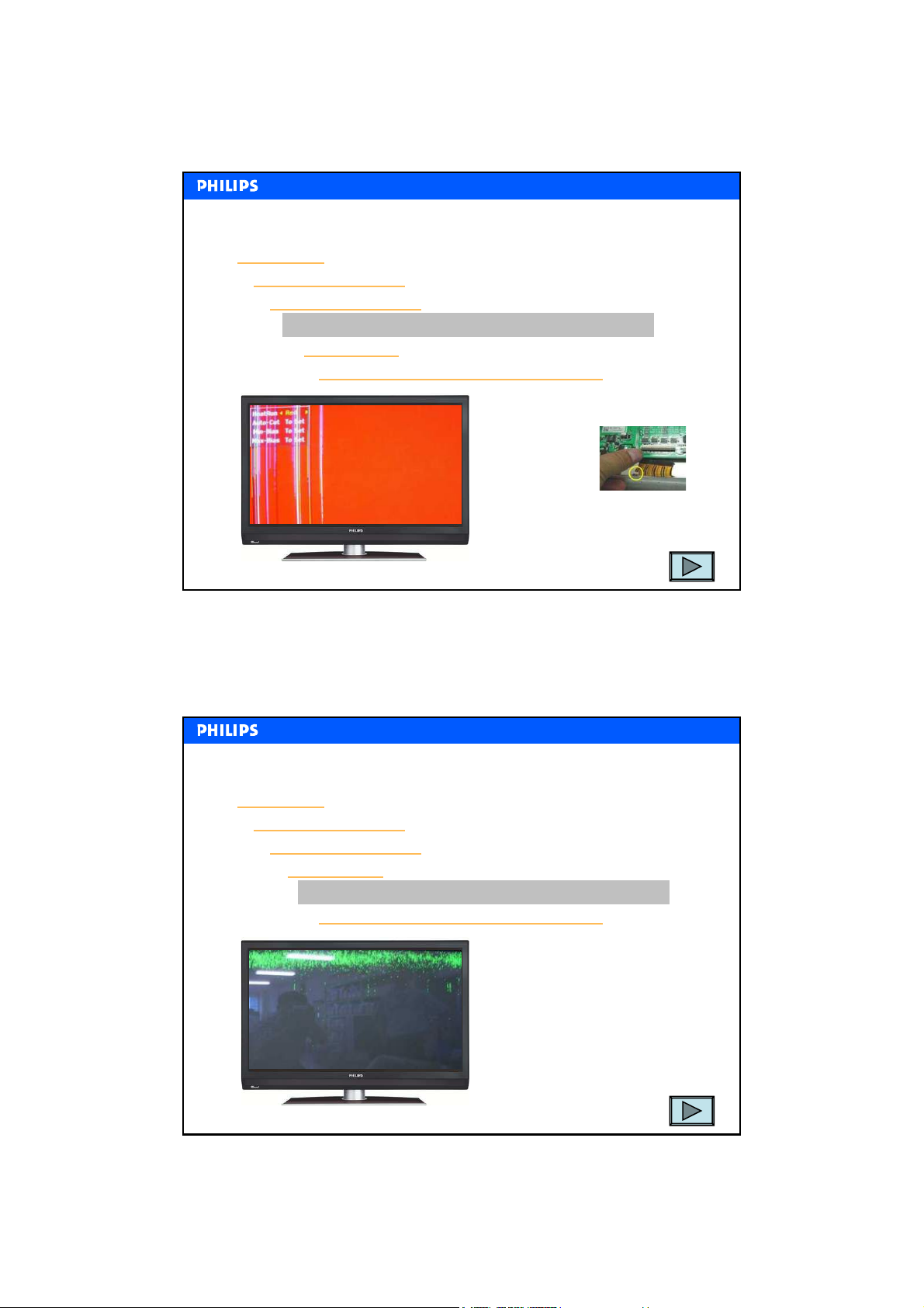
Panel Error Examples and Solutions
Panel Error Examples and Solutions
Vertical line
Vertical black bar (1)
Vertical black bar (2)
Vertical lines
Flicker noise
Image retention, but no image sticking
Check the COF
2.Inspect the
film where
the COF
connects to
the Address
drive board
3.Replace the Plasma panel
Philips CE / Euroservice, L. van der Niet, March 2007, AX67-M07-0026
Panel Error Examples and Solutions
Panel Error Examples and Solutions
Vertical line
Vertical black bar (1)
Vertical black bar (2)
Vertical lines
Flicker noise
Image retention, but no image sticking
Replace the Control Board
1.Check if the screen retains
outlines such as Teletext
and/or menu’s
9
2.Replace the control board
Philips CE / Euroservice, L. van der Niet, March 2007, AX67-M07-0026
10
5
Page 6
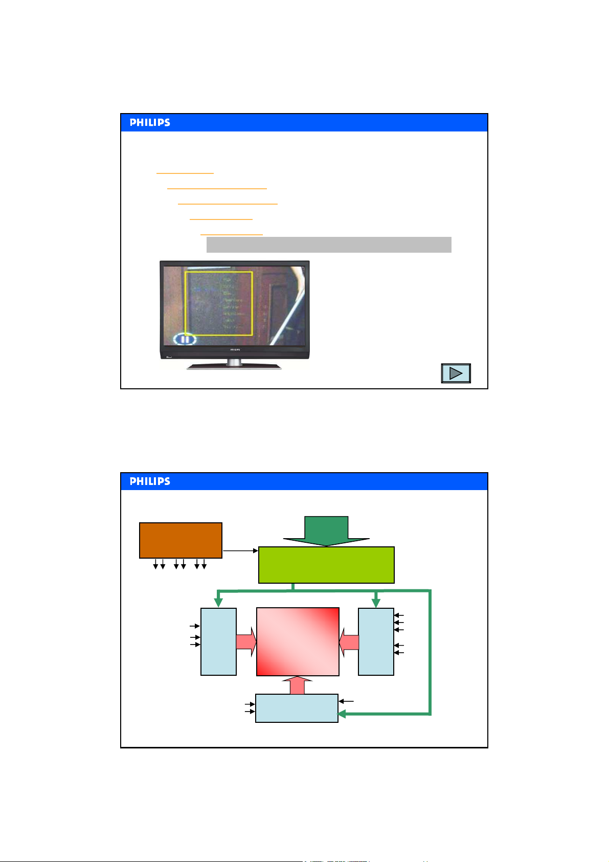
Panel Error Examples and Solutions
Panel Error Examples and Solutions
Vertical line
Vertical black bar (1)
Vertical black bar (2)
Vertical lines
Flicker noise
Image retention (burn-in)
Replace the Control Board
1.Check if the screen retains
outlines such as Teletext
and/or menu’s
2.Replace the control board
Philips CE / Euroservice, L. van der Niet, March 2007, AX67-M07-0026
PDP General Block Diagram
PDP General Block Diagram
Power Supply
Va
Vs
+5V
+15V
Vs
+5V
+15V
Vsc
Vsetup
Scan
sustain
driver
(Y-sus)
+5Vctrl
Plasma Panel
LVDS input
Scan Control
(Control Logic)
common
sustain
driver
(Z-sus)
Vs
Vsetup
Vsc
+5V
+15V
11
+5V
+15V
Philips CE / Euroservice, L. van der Niet, March 2007, AX67-M07-0026
Address driver
(X-sus)
Va
12
6
Page 7
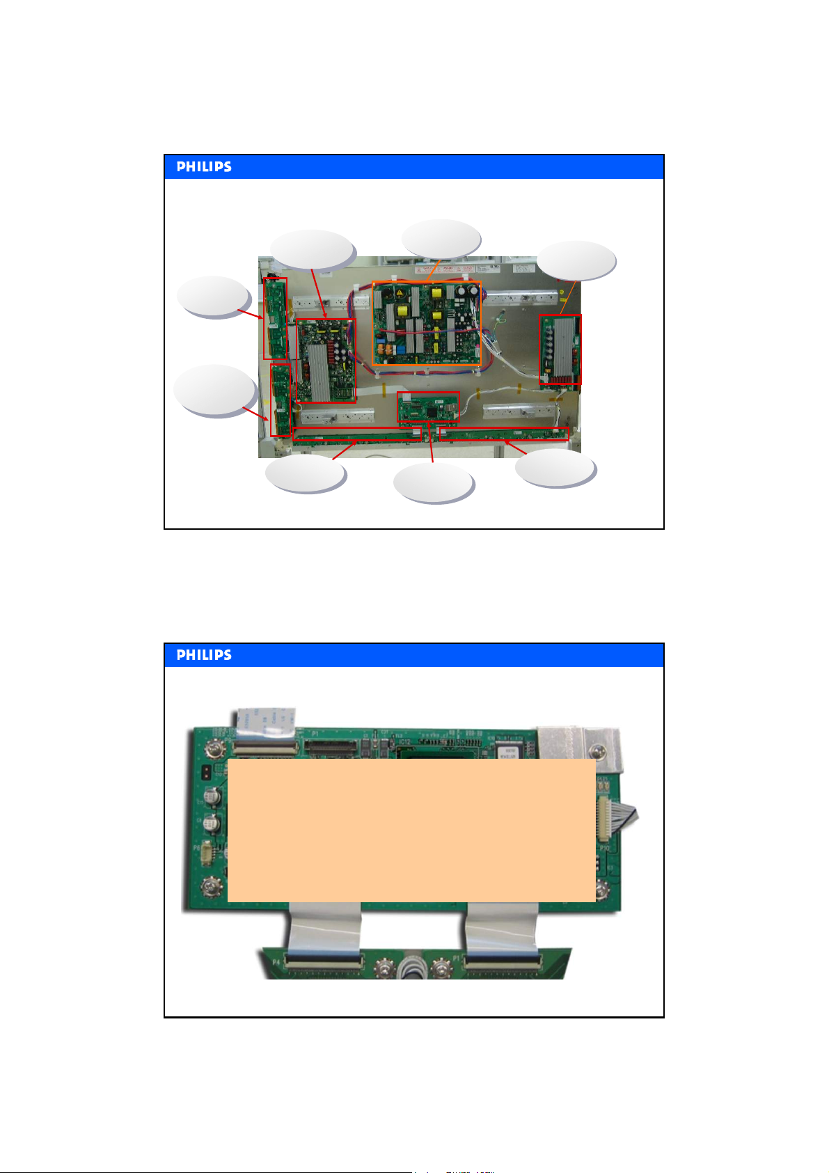
Typical PDP board layout
Typical PDP board layout
Y-DRIVE
Y-DRIVE
Top
Top
Y-DRIVE
Y-DRIVE
Bottom
Bottom
Y-SUS
Y-SUS
X-LEFT
X-LEFT
Philips CE / Euroservice, L. van der Niet, March 2007, AX67-M07-0026
PSU
Control
Control
or Logic
or Logic
Common
Common
Z-SUS
X-Right
X-Right
X- or
X- or
Z-SUS
13
Control Logic Board
Control Logic Board
The Control Board receives the LVDS video signal from the
Television part.
The control Board converts this LVDS signal into
Let’s first have a look at the Control Board
addressing and control signals for the other boards in the
PDP.
Therefore the Control Board has connections to Address,
Scan sustain and Common sustain boards.
Philips CE / Euroservice, L. van der Niet, March 2007, AX67-M07-0026
14
7
Page 8
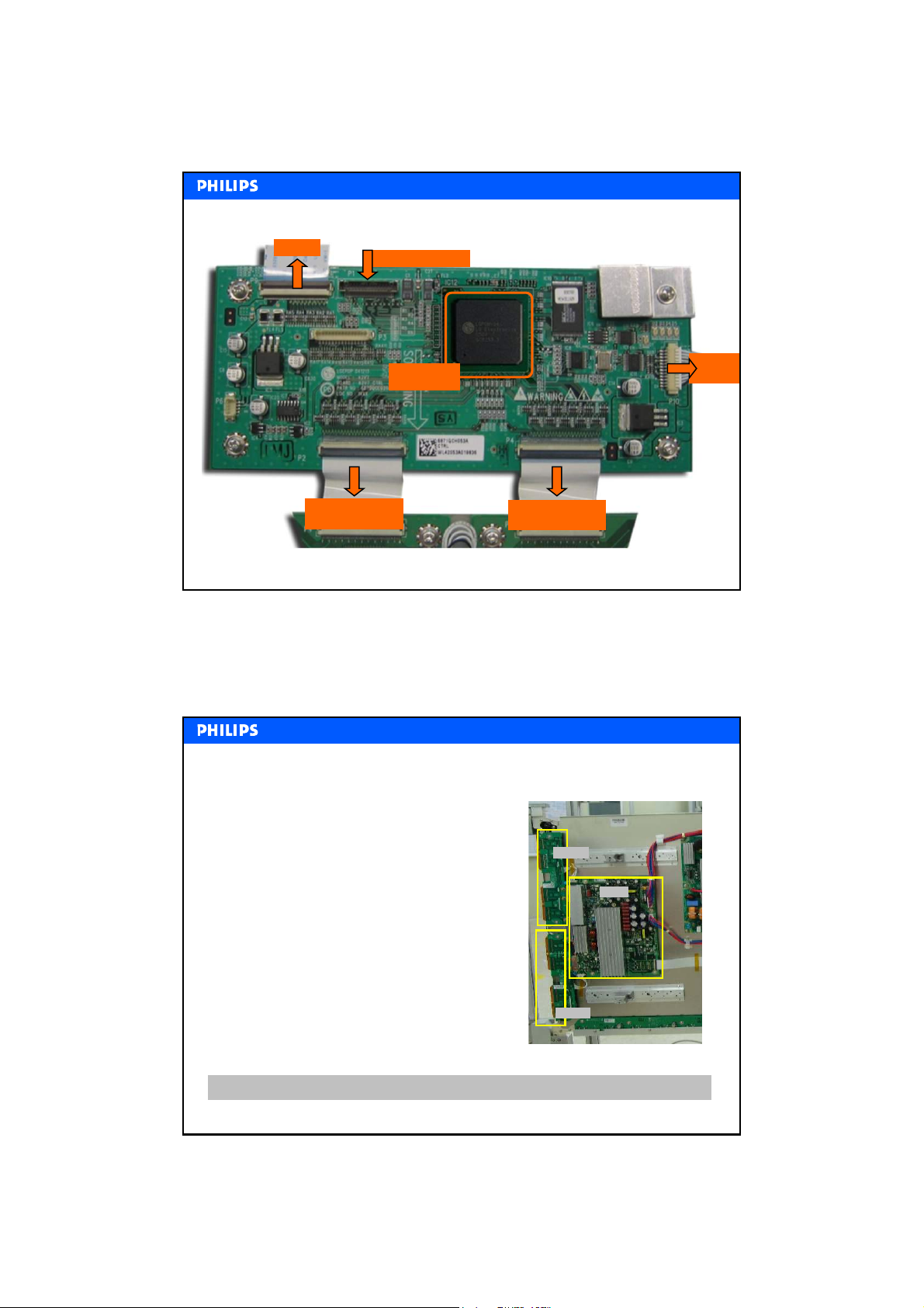
Control Board
Control Board
To Scan
LVDS input signal
Driver
YY--Driver
Addressing signal
to left board
Philips CE / Euroservice, L. van der Niet, March 2007, AX67-M07-0026
MCM
Multi Chip Module
To
Common
Addressing signal
to right board
15
Two Y-driver boards are located on the
left-hand side (looking from the back) of
the TV. Each is supporting half of the
screen. The upper one the top half of the
screen and the lower board the lower half.
The sustain and reset waveform from the
Y-SUS board is passed on via the scan
driver IC's on both Y-boards to the plasma
panel.
In case of a 42 inch screen, 8 scan driver
IC's (4 on each Y-board) are needed to
address every horizontal line (Y sustain
electrode).
Next slide shows how the Y-waveform is built up
Philips CE / Euroservice, L. van der Niet, March 2007, AX67-M07-0026
Y-driver
Y-SUS
Y-driver
16
8
Page 9
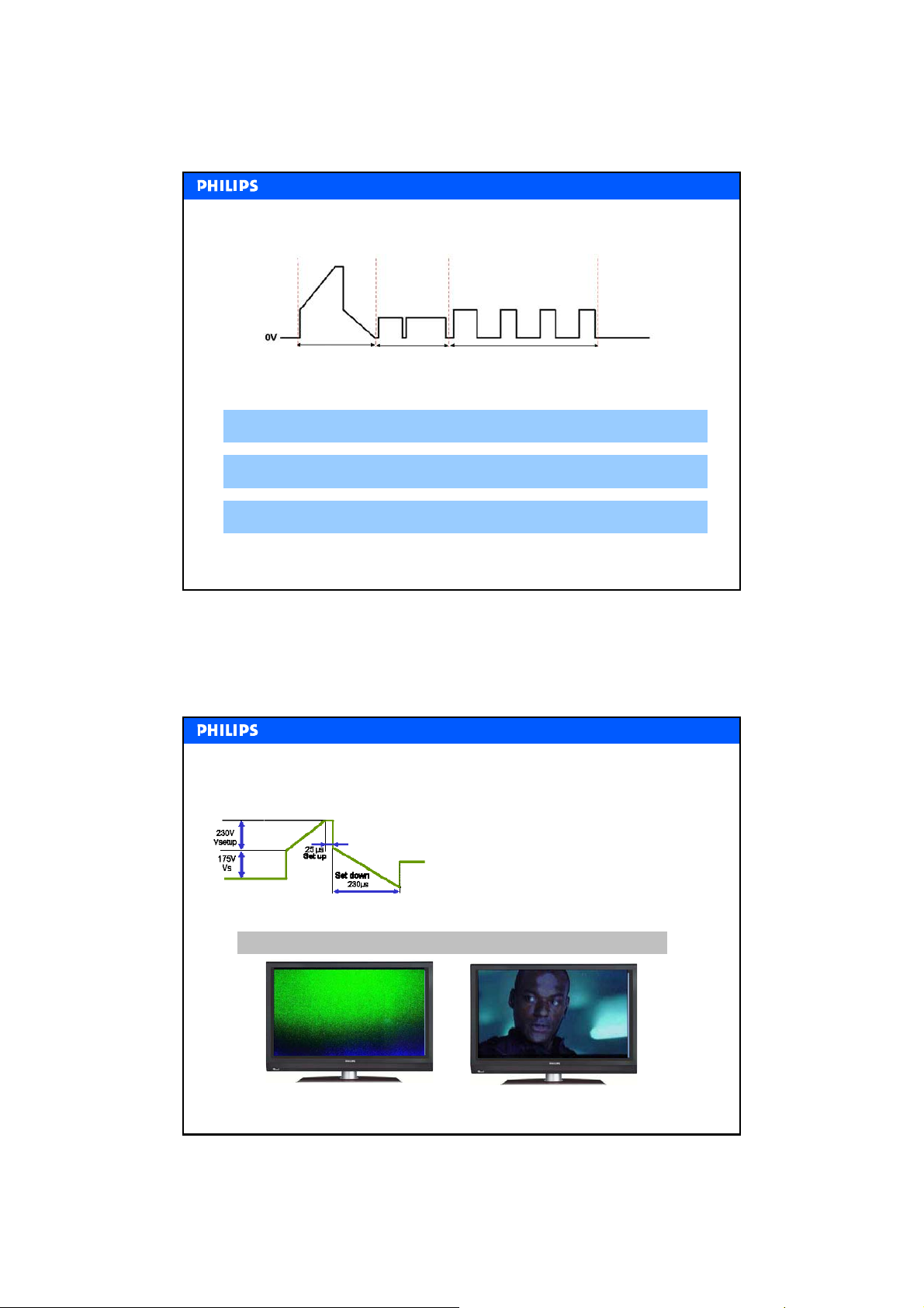
waveform
YY--waveform
Set-up Scan
Sustain
Set-up (or erase) phase Creating the wall-charge
Scan (or address) phase Addressing the sub-pixel to be fired
Sustain phase Generating visible light by addressed sub-pixel
Philips CE / Euroservice, L. van der Niet, March 2007, AX67-M07-0026
Y driver Voltage levels
Y driver Voltage levels
Voltage level is critical to get a good picture.
17
Vs is too low → Too dark picture
(The brightness of the picture will be too low)
Vs is too high
will become too bright
(The brightness of the picture will be too high)
→ Black parts (e.g. shadows)
If Vsetup is not correct, it will result in flicker noise or solarization.
Flicker noise
Philips CE / Euroservice, L. van der Niet, March 2007, AX67-M07-0026
Solarization
18
9
Page 10
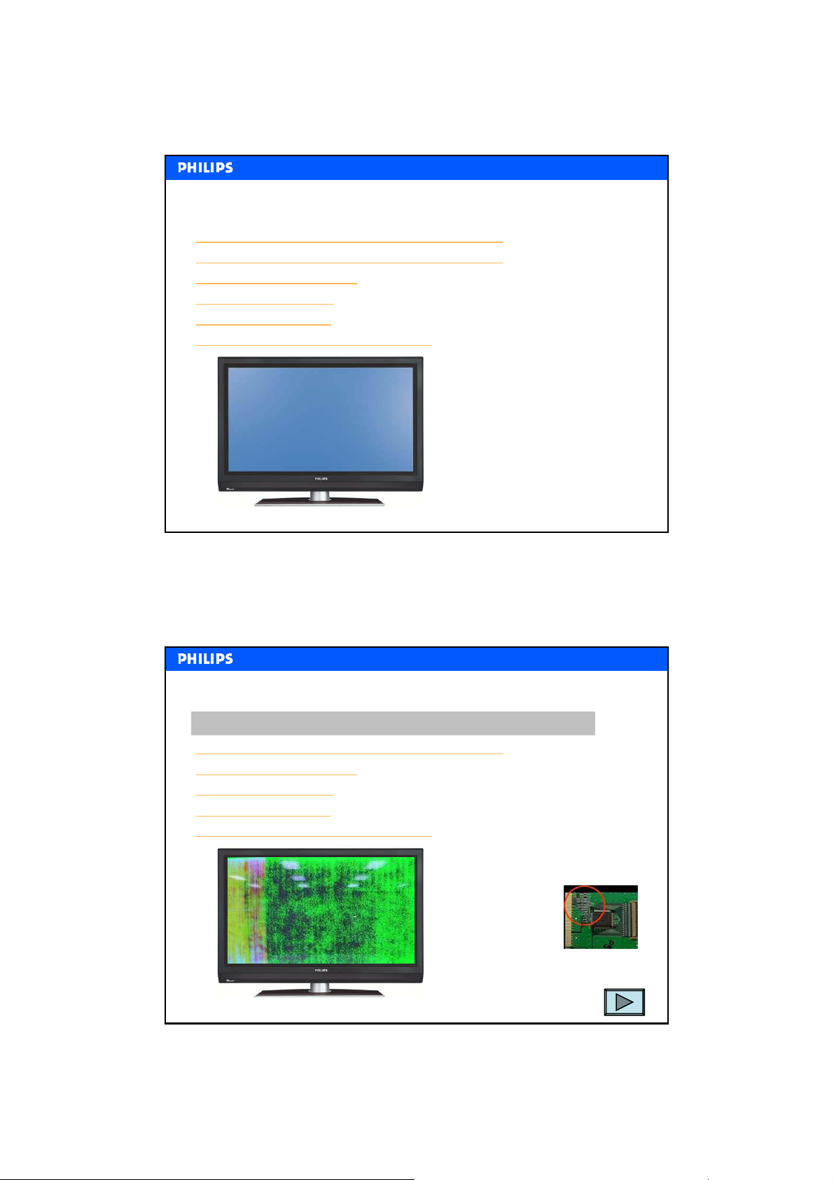
Y board: Error Examples and Solutions
Y board: Error Examples and Solutions
No picture shown and flicker, wrong discharge (1)
No picture shown and flicker, wrong discharge (2)
Large black horizontal bar
Horizontal line or lines
Moving OSD "curtain"
Picture is shown, but wrong discharge
Philips CE / Euroservice, L. van der Niet, March 2007, AX67-M07-0026
Y board: Error Examples and Solutions
Y board: Error Examples and Solutions
No picture shown and flicker, wrong discharge (1)
No picture shown and flicker, wrong discharge (2)
Large black horizontal bar
Horizontal line or lines
Moving OSD "curtain"
Picture is shown, but wrong discharge
Replace the Y-board
1.The SUS-up and SUSdown diodes might be
damaged (check with
Ohm-meter)
19
2.Replace the Y-board
Philips CE / Euroservice, L. van der Niet, March 2007, AX67-M07-0026
20
10
Page 11
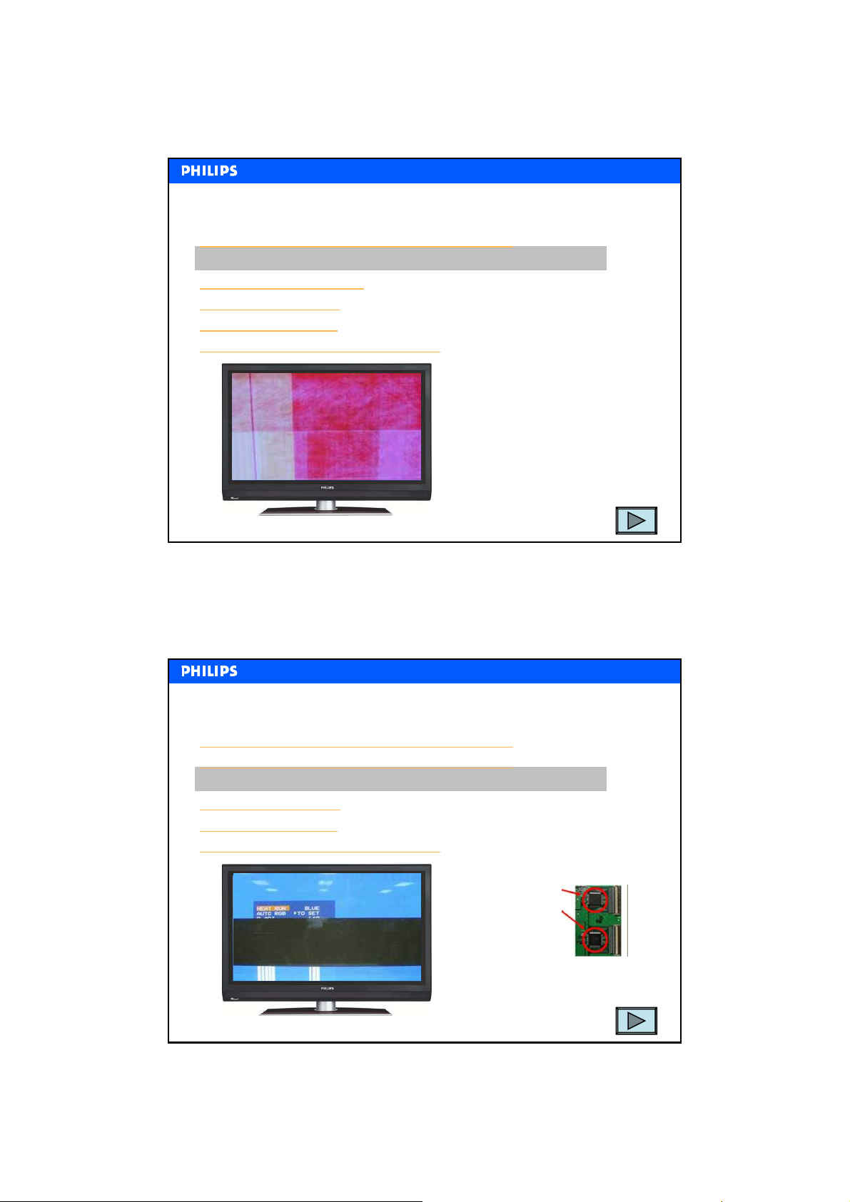
Y board: Error Examples and Solutions
Y board: Error Examples and Solutions
No picture shown and flicker, wrong discharge (1)
No picture shown and flicker, wrong discharge (2)
Large black horizontal bar
Horizontal line or lines
Moving OSD "curtain"
Picture is shown, but wrong discharge
Replace the Y-board
1.Check and readjust voltage levels
of Vs and Vsetup
2.Check if 15V to the Control board
is present
3.Replace the Y-board
Philips CE / Euroservice, L. van der Niet, March 2007, AX67-M07-0026
Y board: Error Examples and Solutions
Y board: Error Examples and Solutions
No picture shown and flicker, wrong discharge (1)
No picture shown and flicker, wrong discharge (2)
Large black horizontal bar
Horizontal line or lines
Moving OSD "curtain"
Picture is shown, but wrong discharge
Replace the Y-board
1.Check the SCAN
driver IC of the Ydriver board
21
2.Check the connector
3.Replace the Y-board
Philips CE / Euroservice, L. van der Niet, March 2007, AX67-M07-0026
22
11
Page 12
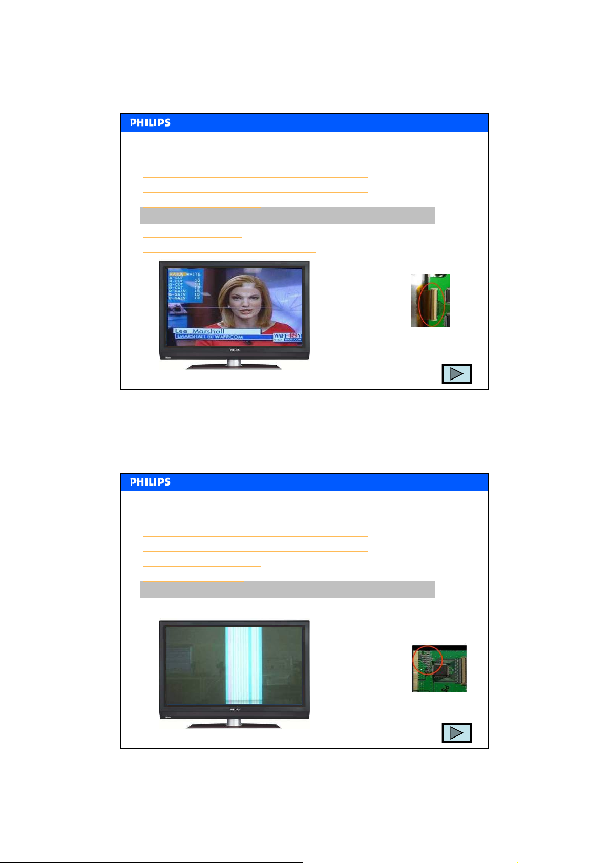
Y board: Error Examples and Solutions
Y board: Error Examples and Solutions
No picture shown and flicker, wrong discharge (1)
No picture shown and flicker, wrong discharge (2)
Large black horizontal bar
Horizontal line or lines
Moving OSD "curtain"
Picture is shown, but wrong discharge
Replace the Y-board
1.The FPC on the Ydriver board is not
well connected or
polluted
2.Reposition and clean the FPC
3.If problem still exists then replace
the Y-board
Philips CE / Euroservice, L. van der Niet, March 2007, AX67-M07-0026
Y board: Error Examples and Solutions
Y board: Error Examples and Solutions
No picture shown and flicker, wrong discharge (1)
No picture shown and flicker, wrong discharge (2)
Large black horizontal bar
Horizontal line or lines
Moving OSD "curtain"
Picture is shown, but wrong discharge
Replace the Y-board
1.The SUS-up and SUSdown diodes might be
damaged (check with
Ohm-meter)
23
2.Replace the Y-board
Philips CE / Euroservice, L. van der Niet, March 2007, AX67-M07-0026
24
12
Page 13
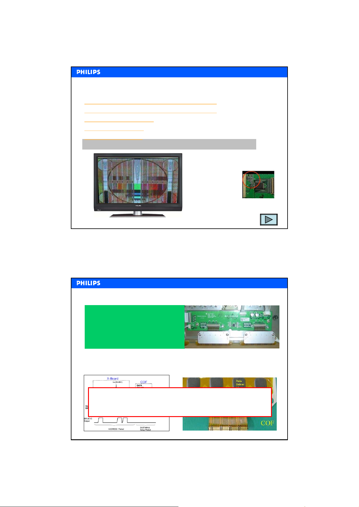
Y board: Error Examples and Solutions
Y board: Error Examples and Solutions
No picture shown and flicker, wrong discharge (1)
No picture shown and flicker, wrong discharge (2)
Large black horizontal bar
Horizontal line or lines
Moving OSD "curtain"
Picture is shown, but wrong discharge
Replace the Y-board
1.The SUS-up and SUSdown diodes might be
damaged (check with
Ohm-meter)
2.Replace the Y-board
Philips CE / Euroservice, L. van der Niet, March 2007, AX67-M07-0026
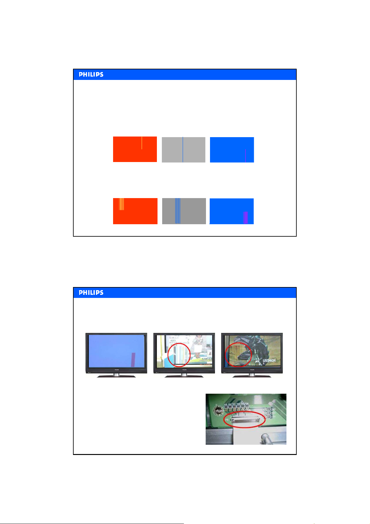
Address (X) --
Address (X)
The X-board generates the address
pulses during the scan phase.
The x-waveform is passed on to the
plasma panel via Chips On Film (COF).
The X-board receives the information, about which pixel should
be turned on and which should be off, from the control board.
board
board
Always handle the COF with extreme care.
If the COF gets damaged, the whole plasma panel
needs to be replaced !!!!
25
Philips CE / Euroservice, L. van der Niet, March 2007, AX67-M07-0026
26
13
Page 14
board trouble shooting
XX--board trouble shooting
A problem with the X-board is recognized by vertical lines / bars on the screen.
Single line failures
One single line having a failure is related to the plasma panel itself and the
panel has to be replaced.
Multiple line failures
With a multiple line failure, the problem is likely to be on the X-board, the
connection between the X-board and the Control board, the Control board
or the COF.
Philips CE / Euroservice, L. van der Niet, March 2007, AX67-M07-0026
board: Error examples and Solution
XX--board: Error examples and Solution
Vertical bar or bars in part of screen
Replace the X-board
1.Check the signal cable from the control board to
the X-board. If not correct replace the cable.
2.Check the 5V power (cable). If not correct change
the power cable or board
3.If the problem still exists or cabling is OK, then
replace the X-board
Philips CE / Euroservice, L. van der Niet, March 2007, AX67-M07-0026
27
28
14
Page 15
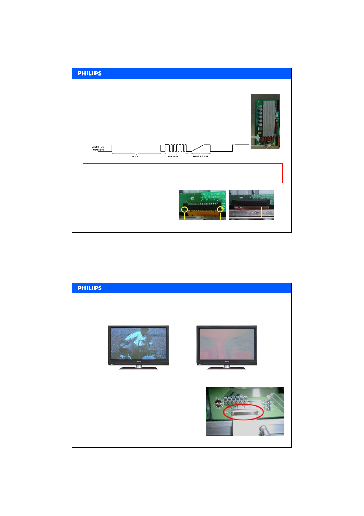
Common sustain (Z)--
Common sustain (Z)
The Z-board provides the signal for the Z-electrodes in
the sustain phase of the sub-pixel. During the scan period
the signal is high and during the sustain period the signal
is alternating on and off opposite to the Y-electrode. The
Z-board is controlled by the Control board.
Be careful when replacing the Z-board. Just like the X and Y board the FPC,
which is part of the plasma panel, must be handled with extreme care.
How to replace the Z-board
1. Unlock the connector
2. Pull out the FPC gently
Board
Board
Philips CE / Euroservice, L. van der Niet, March 2007, AX67-M07-0026
board: Error examples and Solutions
ZZ--board: Error examples and Solutions
Picture is dark and has noise (wrong discharge)
Replace the Z-board
1.Check connectors and cables to the Z-board.
If not correct replace them.
2.Check the input voltages on the Z-board. If
not correct adjust them on the power board.
3.If the problem still exists, then replace the Zboard.
29
Philips CE / Euroservice, L. van der Niet, March 2007, AX67-M07-0026
30
15
Page 16
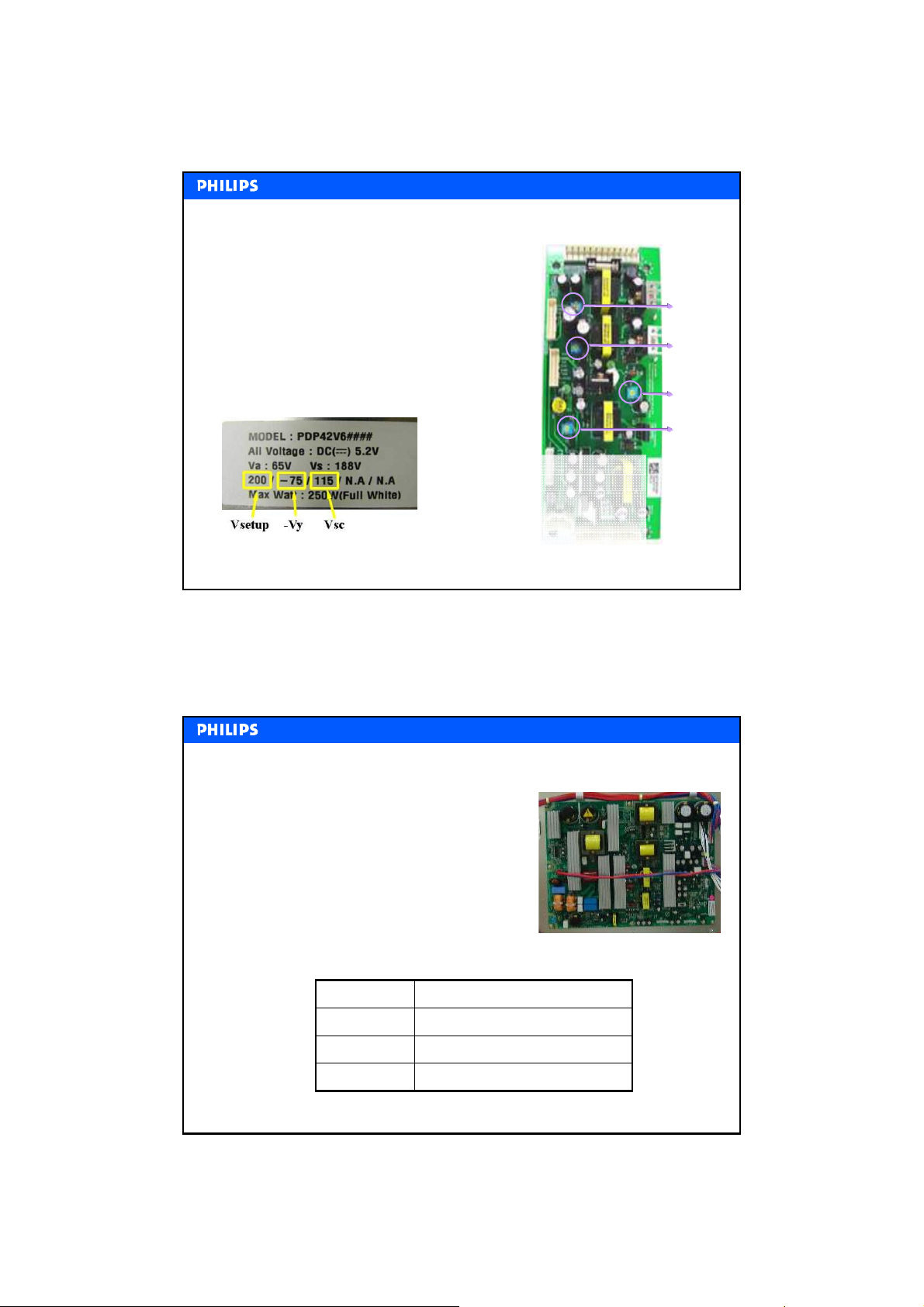
Power Supply
Power Supply
AC / DC
changes the input AC voltage (100~240V) to DC
voltage (380V)
DC / DC
generates a number of DC voltages from the DC
380V DC:
• Low voltages: Stand-By 5V, 5/12/15/30V
• High voltages: Va, Vs, Vset-up, -Vy, Vsc
a
s
set_up
sc
y
Philips CE / Euroservice, L. van der Niet, March 2007, AX67-M07-0026
Typical voltage levels
Vsc
Vsc
Vsetup
Vsetup
Ve
--Ve
Vy
--Vy
~70 V Address Voltage V
~180 V Sustain Voltage V
~265 V Setup Voltage V
~120 V Scan Voltage V
~-75 VV
31
PSU trouble shooting
PSU trouble shooting
The Plasma Display might have an auto-protection
mechanism which shuts the panel down after some
seconds, when there is something wrong in the set.
This could be a wrong voltage level or no specific
power level at.
In case the status indicator LED returns to RED
after a few seconds when switching the set on,
then check if the following voltages are down:
Check Y-SUS, Z-SUS and PSU180V (Vs)
Check X-board75V (Va)
Check Y-SUS or PSU120V (Vsc)
Y-SUS or PSU240V (Vsetup)
Philips CE / Euroservice, L. van der Niet, March 2007, AX67-M07-0026
32
16
Page 17
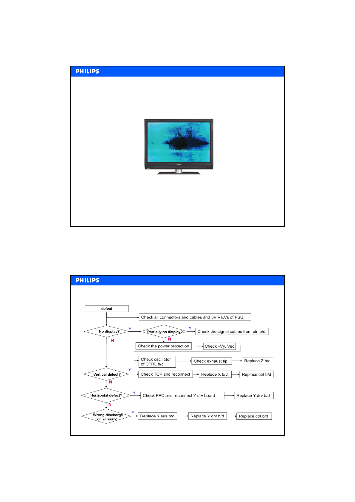
Power Supply error example
Power Supply error example
This is the result when the 15V drops under 14V
• Check the 15V from the Power Supply board
• Check for short circuits on the X-board
• Replace the Power Supply board or the X-board
Check--
Check
Philips CE / Euroservice, L. van der Niet, March 2007, AX67-M07-0026
up Flowchart: Summary
up Flowchart: Summary
33
Philips CE / Euroservice, L. van der Niet, March 2007, AX67-M07-0026
34
17
Page 18
End of Module
End of Module
Basic PDP Trouble shooting
Basic PDP Trouble shooting
Philips CE / Euroservice, L. van der Niet, March 2007, AX67-M07-0026
35
18
 Loading...