

Philips BAQ800 Datasheet

DISCRETE SEMICONDUCTORS
DATA SH EET
, halfpage
M3D119
BAQ800
AM PIN diode
Product specification
File under Discrete Semiconductors, SC01
1997 Aug 26

Philips Semiconductors Product specification
AM PIN diode BAQ800
FEATURES
• Glass passivated
• High maximum operating
temperature
DESCRIPTION
Cavity free cylindrical glass package
through Implotec
(1)
technology.
This package is hermetically sealed
and stress free as coefficients of
expansion of all used parts are
matched.
(1) Implotec is a trademark of Philips.
• Low leakage current
• Excellent stability
• Available in ammopack.
handbook, 4 columns
ak
MAM123
APPLICATIONS
• RF attenuator with low distortion for
Fig.1 Simplified outline (SOD81) and symbol.
frequencies above 100 kHz.
LIMITING VALUES
In accordance with the Absolute Maximum Rating System (IEC134).
SYMBOL PARAMETER CONDITIONS MIN. MAX. UNIT
V
RRM
V
R
I
F(AV)
repetitive peak reverse voltage − 100 V
continuous reverse voltage − 100 V
average forward current Ttp=25°C; lead length = 10 mm;
− 1.25 A
see Fig.2
T
=60°C; printed-circuit board
amb
− 600 mA
mounting (see Fig.17); see Fig.3
T
stg
T
j
storage temperature −65 +175 °C
junction temperature −65 +150 °C
1997 Aug 26 2

Philips Semiconductors Product specification
AM PIN diode BAQ800
ELECTRICAL CHARACTERISTICS
T
=25°C unless otherwise specified; all characteristics must be tested in the dark because of the light sensitivity
j
of this product.
SYMBOL PARAMETER CONDITIONS MIN. TYP. MAX. UNIT
V
F
I
R
τ charge carrier life time when switched from I
C
d
r
D
r
s
forward voltage IF= 100 mA; see Figs 4 and 5 − 0.9 1.1 V
I
= 100 mA; Tj=T
F
j max
;
− 0.7 0.9 V
see Figs 4 and 5
reverse current VR= 100 V; see Fig.14 −−0.1 µA
V
= 100 V; Tj= 125 °C; see Fig.14 −−30 µA
R
= 10 mA to
F
10 20 −µs
IR= 6 mA; measured at 10% of IR;
see Fig.15
diode capacitance f = 1 MHz; see Figs 6, 7, 8 and 9
V
=0 − 10 12 pF
R
V
=2V − 56pF
R
diode forward resistance f = 100 kHz; see Figs 10 and 16
I
=10µA − 3100 6000 Ω
F
I
= 100 µA − 380 800 Ω
F
I
=1mA − 42 80 Ω
F
I
=10mA − 510Ω
F
diode series resistance f = 100 kHz; see Figs 11, 12 and 13
V
= 0 1000 2200 − kΩ
R
V
= 2 V 5000 11000 − kΩ
R
f = 1 MHz; see Figs 11,12and13
V
= 0 25 50 − kΩ
R
= 2 V 100 220 − kΩ
V
R
THERMAL CHARACTERISTICS
All characteristics must be tested in the dark because of the light sensitivity of this product.
SYMBOL PARAMETER CONDITIONS VALUE UNIT
R
R
th j-tp
th j-a
thermal resistance from junction to tie-point lead length = 10 mm 60 K/W
thermal resistance from junction to ambient note 1 120 K/W
Note
1. Device mounted on an epoxy-glass printed-circuit board, 1.5 mm thick; thickness of Cu-layer ≥40 µm, see Fig.17.
For more information please refer to the
“General Part of Handbook SC01”
.
1997 Aug 26 3
Philips Semiconductors Product specification
AM PIN diode BAQ800
GRAPHICAL DATA
1.5
handbook, halfpage
I
F(AV)
(A)
1.0
0.5
0
0 200
DC application.
100
Ttp (°C)
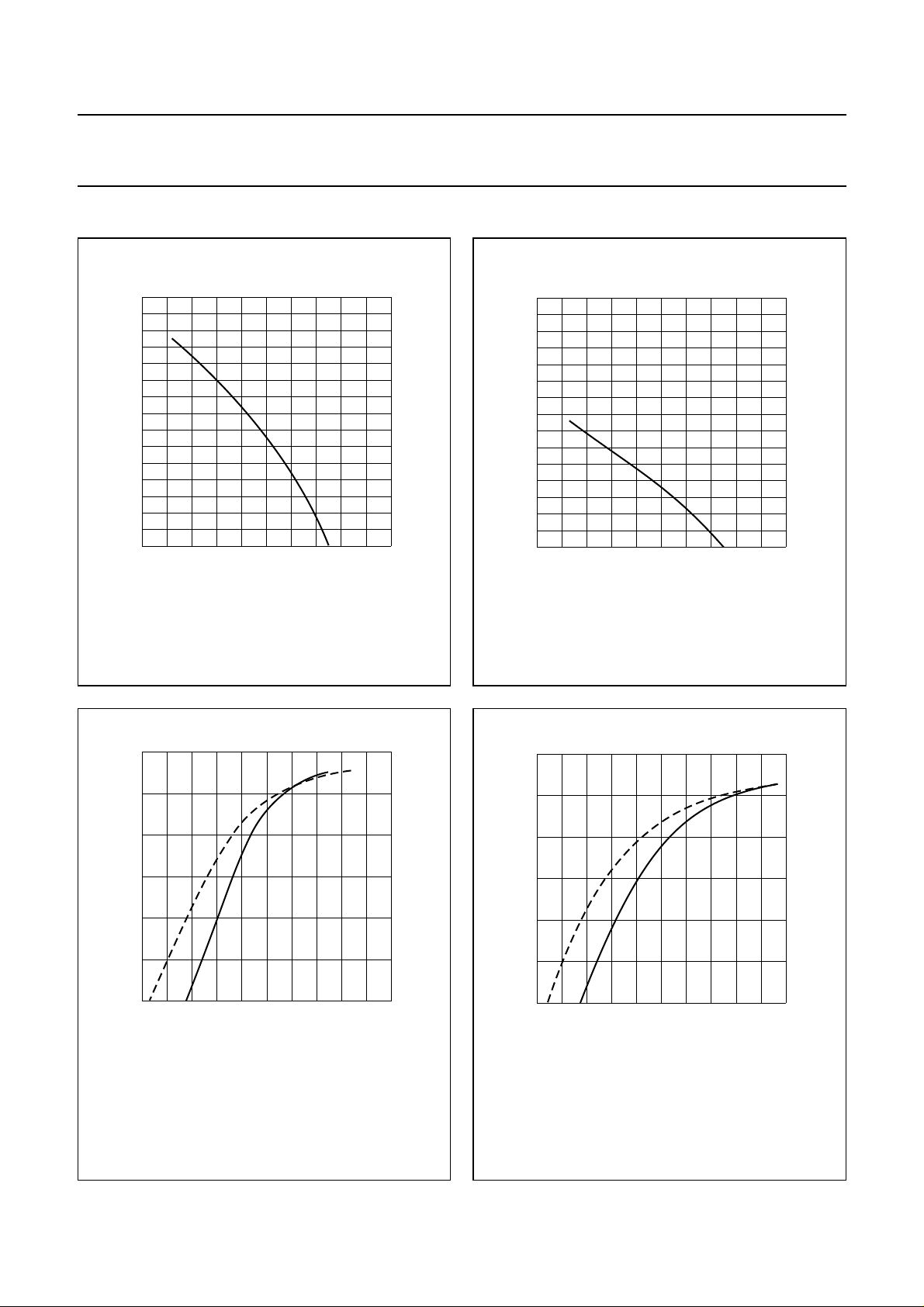
Fig.2 Maximum permissible average forward
current as a function of tie-point temperature.
MGG498
1.5
handbook, halfpage
I
F(AV)
(A)
1.0
0.5
0
0
DC application.
100
T
amb
MGG499
(°C)
Fig.3 Maximum permissible average forward
current as a function of ambient temperature.
200
4
10
handbook, halfpage
I
F
(mA)
3
10
2
10
10
1
−1
10
−2
10
0
Dotted line: Tj= 150°C.
Solid line: Tj=25°C.
Fig.4 Forward voltage as a function of
MGG500
0.4 2.00.8 1.2 1.6
VF (V)
forward current; typical values.
4
10
handbook, halfpage
I
F
(mA)
3
10
2
10
10
1
−1
10
−2
10
0 0.4 2.00.8 1.2 1.6
Dotted line: Tj= 150°C.
Solid line: Tj=25°C.
Fig.5 Forward voltage as a function of
forward current; maximum values.
MGG501
VF (V)
1997 Aug 26 4
 Loading...