

Page 1
AZ8110
AZ8114
V
'GB'
(A) Pad'O-Caiserie “.ecorder/CO-Spi-!?r
(N^ Radiocasaetierecorcer/CO-speler 'i9
(T) Radiocasete/lector cie CD 24
(T) Radioregistraiore/lettore CO 29
(sj
Radiokasseit/CO-spelare
(|f) Radionauhuri/CO-soitin
' : 3
.-r'l-'T' CL.-t
__________________________
jr ::3 CO
PHILIPS
9
14
34
39
Page 2
HOM
Es necesario que lea cuidadosamente su in
structivo de manejo.
(||) English
Illustrations
Guarantee and ser'.'ice
INDEX
page 4
page 3
pages 44-46
tu
I V-EKfiaUE QUE EL VOLTAJE DE AUVEf^ACO'J
I
SEA EL P-EQUETuD O PAÍ5A SU APA'ÍATO
PARAELTTAREL RESGO DE CHOQUE ELECTR.CO. f.O QUITE lATAPA,
EN CASO DE P.EQU£ií.3SEW.'iaO, D TJJASE AL PERSO'JAL AVTOPJZADO DE PHTJPS |
Danmark
Typeskiltet findes pa undersiden af apparaten.
Dette produkt overholder kravene til radio-
interferens af Europaeisk F^llesskab.
Betnaerk: Netafbryderen POWER er sekundart
indkoblet og afbryder ikke strommen fra nettet.
Den indbyggede netdel er derfor tilsluttet til lysnettet sa tenge netstikket sidder i stikkontakten.
Advarsel: Usyniig laserudstraling ved abning nàr
sikkerhetsafbrydere er ude af funktion. Undga
uds^ttelse for straling.
Garanti og service sider 44-46
CD Norge
Typeskilt finnes pa apparatene underside.
Observer: Nettbryteren POWER er sekundert
innkoplet. Den innebygde netdelen er derfor
ikke frakoplet nettet sa lenge apparatet er til
sluttet nettkontakten.
Garanti og service sider 44-46
CE) Français
Illustrations
Garantie et sen/ice après-vente
CD Deutsch
Abbildungen
Garantieleistung und Service
Amtsblatt
(D Nederlands
Afbeeldingen
Garantie en seance
CD Español
Ilustraciones
Garantía
CD Italiano
Illustrazioni
Garanzia e sea^ízio
pages
psQe 3 Ç
pages 44-46
Seite 14
Seite 3
Seiten44-46 £
Seite 43
pagina 19 c
pagina 3
pagina's 44-46 'g
página 24
página 3
páginas 54-55
pagina 29
pagina 3
pagine 44-46
■ö
o
es
O'
u.
o
H
o
iC
es
a
w
LU
o
c
.5
CD Svenska
Figurer
Garanti och service
(|f) Suomi
Kuvat
Takuu ¡a huolto
sida 34 .te
sida 3 §
sidorna 44-46 >
sivu 39 g
Sivut 44-46
w
3
W
Page 3
s и type D*cells - R20 - UM1
0 0
......
Il t
jl
i
11^
-IL
'0
Jl
{
Il }
,Jl- -
O
ACMAIWS VOLTAGE
Page 4

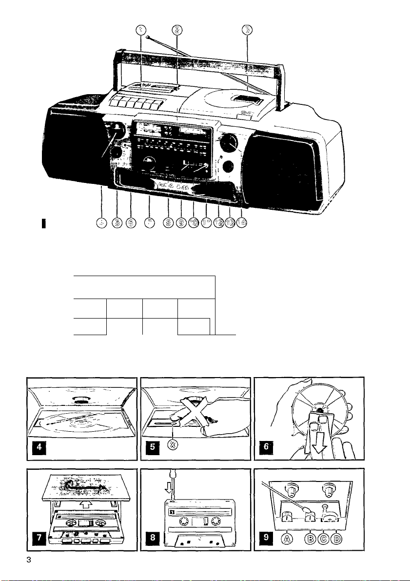
CONTROLS
TOP AMD FRONT PANEL - fig, 1 SUPPLY
................................ ............
For the illustrations, keep page 3 open
© cassette deck keyboard:
■ STOP/EJECT
• RECORD
► PLAY
•« REWIND - fast rewind
►► F.FL'VD - fast forward wind
HPAUSE
© CD keyboard and display ,
lll►-PL.AYI►■эnd PAUSEllbuttgn. _ _ "
a-STOP button
№« PREVIOUS/l\IBXT»i and SEARCH»):
w PREVlOUS/NEXT»i:
in position playback or STOP, press briefly to
jump to a previous r« or next track
SEARCH »:
during playback, keep pressed to search fast
backward i«i or forward w
INTROSCAN - to play only the beginning of each
track
REPEAT - to repeat continuously the disc or the
stored selection (memory)
press again to defeat the REPEAT function
CLEAR - to erase the memory
DISPLAY - to display all stored track numbers
STORE - to store the displayed track number in
the memory
CD display, shows:
-----
; - - please wiait
TRACK - the total number of tracks
and during PLAY the number of the track being
played
TIME - the total playing time of the disc
and during PLAY the elapsed time of that track
REPEAT activated
MEMORY - the stored selection (memory) is
played
SCAN (INTROSCAN) activated
PAUSE activated
@ OPENfCLOSE to open and close the CD cover
® VOLUME control
® POWER button with ON indicator
® 0 PHONES stereo headphone socket
@ BASS/TREBLE tone control
® MODE selector - to select the sound source
TUNER-TAPE-CD
® BAND selector
® PM MONO/STEREO sv^iitch
© Flv) STEREO S:-indicator - lights up when receiv
ing an FM stereo station
® MIC - microphone socket
® TURBO BASS GENERATOR bass button with in
dicator press to boost the bass response
@ TUNING knob
BACK PANEL-fig. 3
______________________________________
Batteries
Whenever convenient, use AC mains supply if you
want to consen/e batten/ life.
• Open the battery compartment (fig. 2).
" Insert as indicated eight (preferably Alkalmel bat
teries, b/pe R20, UM1 or D-cells (fig 2)
•_ The batten/ supply is switched.off when the set
js connected .to the meins VVhsn changing over to
/batten/ supply, pull out the plug from the AC
I’yiAINS socket ig' (fig. 3)
• Remove the batteries if exhausted or if they will
not be used again for a long period.
Mains
• Check if the mains voltage as shown on the t^'pe
plate corresponds to your local mams supply If it
does not, consult your dealer or sewice organisa
tion.
If the set is equipped with a VOLTAGE selector ©
{fig. 3), set this selector to the local mams voltage
• Connect the mains lead to the AC MAINS socket
® (fig. 3) and the wall socket. The mams supply is
now' switched on
• To disconnect the set from the mams completely,
withdraw the mains plug from the wall socket.
Important note for users in U.K.;
When fitting a mains plug to the mams lead proceed as
follows
The wires in the mams lead are coloured in accordance
with the following code Blue=Neutral, Bfown=Live
These colours may not correspond with the colour
markings identifying the terminals in your plug, so pro
ceed as follows
Connect the Brown wire to the terminal marked L or
coloured Red
Connect the Blue wire to the terminal marked M or
coloured Black.
Do not connect either wire to the earth terminal in the
plug, marked E or -tor coloured green, or green and yel
low
Note: This apparatus must be protected by a 3 Amp
Fuse if a 13 Amp plug is used or, if any other b/pe of
plug IS used, by a 5 Amp Fuse either in the plug or
adapter or at the distribution board. If m doubt consult a
qualified electrician
@1 CD OUT sockets - for CD-reproduction through
e.g. your stereo system
AC MAINS - socket for mains lead
@ VOLTAGE selector (not on all versions)
The type plate is located on the base of the set.
Page 5

CONNECTIONS
TUNER
CONNECTIONS • fig. 1 and 3
Stereo headphone socket ©O PHONES
For stereo headphones with 3.5 mm plug. Inserting
the plug will disconnect the loudspeakers.
CD Output sockets CD OUT @
Cinch-sockets for CD-reproduction (not radio or cas
sette) through e.g. your stereo system.
• Connect the CD OUT sockets @ to the input sock
ets LINE IN, AUX or CD of the other set.
The CD OUT output signal is not affected by the posi
tion of the controls VOLUME BASS/TREBLE ©
and TURBO BASS GENERATOR ®.
Socket for microphone @ MIC
For a microphone with 3.5 mm plug.
To avoid disturbing noises, reduce the VOLUME ®
before connecting the microphone.
- 'Public address': you can reproduce your voice am
plified through the loudspeakers: set the MODE
selector ©to TAPE.
- Disc-jockey: you can mix your voice with the CD,
TAPE or TUNER: set the MODE selector © to CD,
TAPE or TUNER. In the CD or TUNER mode, you
can record it all on the cassette deck.
Adjust the sound with the controls VOLUME @,
BASS/TREBLE © and TURBO BASS GENERATOR ®.
If a howling sound occurs, keep the microphone away
from the loudspeakers or reduce the VOLUME ©.
Disconnect the microphone when not in use.
RADIO RECEPTION
• Switch on the set using the POWER button ©.
• Set the MODE selector ©to TUNER.
• Adjust the sound with the controls VOLUME ®,
BASS/TREBLE © and the TURBO BASS GENERA
TOR bass button ®
• Select the wave band using the BAND selector.®.
(SW and LW not on all versions).
- For FM, pull out the telescopic aerial. To improve
FM-reception, incline and turn the aerial. Reduce
its length if the FM-signal is too strong (very close
to a transmitter).
- For AM/MW and LW (Medium and Long Wave),
' the set is provided with a built-in aerial, so there is
no need to use the telescopic aerial. The aerial can
be directed by turning the whole set.
- For Short Wave (SV^, the telescopic aerial must
be pulled out and placed in the vertical position. To
improve SW-reception, vary the length of the aeri
al.
• Tune to a radio station using the TUNING knob ®.
• When FM STEREO ♦ ® lights up, you are receiv
ing a FM-stereo transmitter. A disturbing noise, due
to a weak FM-stereo signal, can be suppressed by
setting the FM MONO/STEREO button ® to FM
MONO JL. FM STEREO ♦©will then go out and you
will hear (and record) the FM programme in mono.
• Always switch off the set after use with POWER
button ®.
£
10
O)
c
lU
_(0
'5
o-
c
(0
3
01
Q
V)
•3
c
•D
O
Z
o
1C
n
a
(A
lU
o
c
(/)
V)
«
(0
M
c
0)
>
E
o
3
Page 6

COMPACT DISC
PLAYING A DISC
m
3
• Switch on the set using the POWER button (|).
(O
• Set the MODE selector ©to CD; on the display ap
pears
------
• Adjust the sound with the controls VOLUME ©,
BASS/TREBLE©and TURBO BASS GENERATOR ®.
• Press OPEN/CLOSE ©to open the disc cover.
• Insert the disc, printed side facing up (fig. 4).
• Close the cover. The CD-player starts and scans
the contents list of the disc. After that, the total play
ing time and the number of tracks appear on the dis
play and the CD-player stops.
• Playback will start by pressing PLAY ►. As soon as
playback starts, the display shows the track number /
and the elapsed playing time of the first title. When
the second title is reached the track number 3 ap
pears, etc.
• For brief interruptions, press PAUSE ll The word
PAUSE then appears. To continue playback, press
PAUSE again.
• To stop playback, press STOP*.
The CD player also goes to position STOP:
- by pressing OPEN/CLOSE ©;
- when the end of the disc is reached;
- if you move the MODE selector©;
- by switching off the set;
- if the batteries run down or if the power supply is
interrupted in another way.
• To take out the disc, open the disc cover by press
ing OPEN/CLOSE ©. Open the disc cover only if the
CD-player is in position STOP.
• Always switch off the set after use with POWER but
ton©.
Remarks
- If the battery voltage is not sufficient any more for
playing a disc, the CD-player will not start.
- If
not read the disc. Possible causes are:
REPEAT
If you want to repeat the whole disc (or the stored
selection) continuously, press REPEAT: the word RE
PEAT appears.
The REPEAT function can only be switched on during
playback: PLAY or INTROSCAN.
To defeat the REPEAT-function, press REPEAT again
and the word REPEAT disappears.
: -
------
; - - does not disappear, the CD-player can
- you inserted the disc the wrong way: the label
should face up (fig. 4);
- the surface of the disc is badly scratched or
dirty, see 'Maintenance';
- the lens ® (fig. 5) is steamed up because of a
sudden transition from a cold into a warm environ
ment; do not clean the lens, but let the set accli
matize for a while.
________________________________________________
INTROSCAN
The INTROSCAN function can be switched on from
the STOP and PLAY mode.
• Press INTROSCAN. The word SCAN then appears.
Only the first few seconds of each track are played,
but always from track number /.
• The moment you press PLAY ►, the INTROSCAN
function is defeated (the-word SCAN disappears) and
the disc is played in the normal way from this track
number.
• If you press or kn. the INTROSCAN function re
mains operative and the beginning of the next »w or
previous track is played.
• If INTROSCAN is not defeated by pressing PLAY ►
or STOP it the CD player returns to STOP as soon as
the end of the disc is reached.
m PREVIOUS/NEXT w -1« SEARCH w________________
1. m PREVIOUS/NEXTm
Press briefly (less than 1 second)
a. During PLAY and INTROSCAN: »1 - go to the next track (title)
You can jump to the next title by pressing »w once.
If you want to skip more than one track, then
press MH more than once until the display shows
the desired track number.
- go to the previous track (title)
If you want to repeat the running title from the be
ginning, press once.
If you want to repeat one of the previous titles,
press 1« more than once until the display shows
the required track number.
b. In position STOP:
In position STOP with a disc inserted you can se
lect the desired title using km and until the dis
play shows the required track number.
2. SEARCH >*t
During playback, keep for search forward and km
for search backward pressed. The disc is played
partly and at high speed, however, the sound is
still recognizable.
Release the button as soon as you recognize the
required passage; the disc will be played in the
normal way from this passage.
If the button is pressed longer than 10 seconds,
the search speed increases.
Page 7

COMPACT DISC
CASSETTE
PROGRAMMIIMG TRACK NUMBERS
You may select a number of tracks and store these in
the memory in the desired sequence. When playing,
you wiil only hear the stored titles in the selected se
quence. At most, 26 tracks can be stored in the
memory. You may store each track more than once.
Manual selecting
• Load the disc, but do not press PLAY ►yet.
• Select the desired track using the buttons r« and
►w until the display shows the required track number.
• Store this track by pressing STORE.
• Select and store in this way all desired titles.
Storing during iNTROSCAN
• Press INTROSCAN to play the first few seconds of
each track.
• Press STORE as soon as you recognize a desired
title.
Storing during PLAY
• During normal PLAY you may store the running ti
tle by pressing STORE.
- After pressing STORE the character P (PROGRAM)
appears, indicating that the track has been stored.
- Store all desired titles in the required sequence.
You may store each track more than once.
- At most, 26 tracks can be stored in the memory.
When the memory is full, the character F (FULL) ap
pears.
- When pressing DISPLAY, the display will show in
sequence ail stored track numbers.
- You can simply erase the whole memory by press
ing CLEAR: the character C for CLEAR appears now.
The contents of the memory are also erased:
- by opening the disc cover using OPEN/CLOSE (|);
- if you move the MODE selector®;
- by switching off the set;
- if the batteries get exhausted or if the power
supply is interrupted in another way.
How to play the stored selection
To play your selection, the CD-player should be in po
sition STOP; then press PLAY ►: now, the word
MEMORY appears.
________________
RECORDING
Preparation
• Switch on the set using the POWER button ®.
• Press EJECT »to open the cassette holder.
• Insert the cassette (fig. 7).
For recording you must use a cassette on which the
tabs (fig. 8) are not broken out.
At the very beginning of the tape, no recording will
take place during the first 7 seconds when the leader
tape passes the recorder heads.
• When monitoring during recording, adjust the
sound with the controls VOLUME ®, BASS/TREBLE
® and TURBO BASS GENERATOR ®. These con
trols do not affect the recording.
Recording from the CD-piayer
• Set the MODE selector (f) to CD. It's not neces
sary to start the CD-player separately: if you press
RECORD •, the CD-player starts automatically:
- if the CD-player is in position STOP, recording will
start from the beginning of the disc (or from the
beginning of the programmed selection);
- if the CD-player is in position PAUSE, recording will
start from this very position;
- in position SCAN the CD-player will first return to
the beginning of that track and then recording will
start.
Recording from the radio
• Set the MODE selector ® to TUNER.
• Tune to the desired radio station.
• In case of FM radio recordings, set the FM MONO/-
STEREO button ® to the desired position.
Microphone recording
• Connect the microphone to the socket MIC ®.
- Microphone only: set MODE selector ® to TAPE;
- Mixing with CD: set MODE selector ©to CD;
- Mixing with radio: set MODE selector ® to
TUNER.
• If a howling sound occurs:
- keep the microphone away from the loudspeakers,
- or reduce the VOLUME ®,
- or use headphones for monitoring.
Starting and stopping the recording
• Start recording by pressing RECORD •; in doing
so, PLAY ► is pressed too.
• For brief interruptions, press PAUSE II To restart
recording, press this button once more.
• To stop recording, press STOP ■. On pressing
again, the cassette holder will open.
• Always switch off the set after use with POWER
button ®.
JH
"5
Ul
c
Page 8

CASSETTE
MAINTENANCE
COPYRIGHT
Recording is permissible insofar as copyright or other
m
3
rights of third parties are not infringed.
S.
w'
For U.K. only: Recording and Playback of material may
3
"
require consent. See Copyright Act 1956 and The Per
former's Protection Acts 1958 to 1972.
FAST WINDING
Press or ►►. To stop fast winding, press STOP ■.
SAFEGUARDING AGAINST ERASURE
Keep the cassette side to be safeguarded in front of
you (fig. 8) and break out the left tab. Now, recording
on this side is no longer possible.
You can render this safeguard ineffective by covering
the aperture with a piece of adhesive tape.
CASSETTE PLAYBACK_________________________________
• Switch on the set using the POWER button (|).
• Set the MODE selector d) to TAPE.
• Adjust the sound with the controls VOLUME ©,
BASS/TREBLE @ and TURBO BASS GENERATOR
• Press EJECT Band insert a recorded cassette (fig. 7).
• Fast winding and rewinding: Press ■« or ►►. To
stop, press STOP B.
• Press PLAY ► and playback will start.
• To stop playback, press STOP B.
When the end of the tape is reached, the recorder
buttons are released.
• Always switch off the set after use with POWER
button ©.
_______________________________________
________________
MAINTENANCE
CD-player and discs
- The lens ® (fig. 5) should never be touched or
cleaned.
- The lens may steam up when the set is taken from
a cold into a warm environment. Playing a disc is not
possible then. Do not clean the lens, but let the set
acclimatize for a while.
- Always pick up the disc by the edge and put it
back in its box immediately after use.
- To clean, breath on the disc and wipe it off in a
straight line from centre to edge (fig. 6) using a soft,
lint-free cloth. Cleaning agents may harm the disc.
Cassette deck
To ensure a good recording and playback quality,
clean the parts ® ® © (g) indicated in fig. 9 after ev
ery 50 hours of operation or, on average, once a
month.
• Open the cassette holder by pressing EJECT B.
• Use a cotton bud slightly moistened with alcohol
or a special head cleaning fluid.
• Press PLAY ► and clean the rubber pressure roller
© (fig. 9).
• Then press PAUSE Hand clean the magnetic heads
® © and the capstan ©.
• After cleaning, press STOP B.
Cleaning of the magnetic heads ® © can also be
done by playing the cleaning cassette SBC 114
through once as an ordinary cassette.
Remarks
- The CD-player and the cassette decks are fitted
with self-lubricating bearings which must not be oiled
or greased.
- Fingerprints, dust and dirt on the apparatus can be
removed using a soft, clean and slightly damp leather
cloth. Do not use any cleaning agents, since they
may affect and harm the cabinet.
- Keep the set, batteries, discs and cassettes away
from rain, moisture, sand and excessive heat, e.g.
near heating equipment or in cars parked in the sun.
This product complies with the radio interference re
quirements of the European Community.
Page 9

43
Page 10

GUARANTEE AND SERVICE FOR UNITED KINGDOM
Philips sell ti\is product subject to the understending that if any defect in manufacture
or matenal shall appear in it within 12 months from the date of consumer sale, die
dealer from v^iom the product v/as purchased v/ill arrange for such defect to be recti
fied v^thout charge, proflded.
1. Reasonable evidence is supplied that the product v^s purchased vwthin 12 months
prior to the date of claim.
Z The defect is not due to use of the product for other than domestic purposes, or on
an incorrect voltage, or contra ly to the Comf^ny's operating Instructions, or to acci
dental damage (whetiier in transit or othenwe), misuse, neglect or inexpert repair.
Products sent for service should be adequately packed as no liability can be accepted
for damage or loss in transit, and name and address must be enclosed.
Facts about free service
When*'seivic» is required, apply to the dealer from vAom the product v;as purchased.
Should any difficulty be experienced in obtaining Serwce. e g. in the event of the deal
er hawng ceased to trade, you are advised to contact Philips Senrice.
These statements do not affect the statutory nghts of a consumer.
If VT3U have any questions which your dealer cannot answer, please vmite to
Philips Consumer Relations, S P. 0. Box298,420London Road,
CROYDON CR930R,Oi Ж (01J 683-2166 Consumer Advice.
Please retain this card. Produce if service is required.
GUARANTEE AND SERVICE VAUD FOR IRELAND
This apparatus is made of high quality matenal and great care has been taken in its
manufacture.
Philips, therefore, give you a guarantee on parts agamst failures arising from fault/
workmanship or matenal for 12 months after date of purchase. This guarantee is valid
on the condition that this certificate is completed and signed immediately on delivery
of the apparatus. In case of failure ask v^our dealer for fuller information.
If you have any questions vriiich yw dealer cannot answer. yo\j may apply to
Philips Electrical (Ireland) Lid., Service Department, Newstead, Clonskeagh,
DUBUN 14,9 693355.________________________________________________________________
GUARANTEE AND SERVICE VAUD FOR AUSTRAUA
The benefits grv'en to the purchaser by this vvarranty are in addition to all other rights
and remedies, which, under the Trade Practices Act or other Commonwealth or State
la'.v, the purchaser or owner has In respect of the product
The Philips product carries tiie folio/ring v/arranties'
C-series Hifi-systems. 12 months. Compact Disc Players: 12 months Home Audio
Systems. 6 months. Clock radios, portable radios, cassette recorders, cassette players
and radio recorders' 80 days
Any defect in materials or werkmanship occurring vnthin the specified period from the
date of delKery, be rectified free of charge by the retailer from vriiom this product
vras purchased.
Note: Please retain your purchase docket to assist prompt serrice.
Conditions of this warranty
1. All claims for v^arranty service must be made to the retailer from vriiom this prod
uct vras purdiased. All transport charges incurred in connection vrith v/arranty serwee or replacement will be paid by the purdiaser.
Z These v/arranties do not co^'er batteries and extend only to defects in materials or
workmanship occurring under normal use of the product wfiere operated in accor
dance vrith our instructions.
Philips Consumer Products Division, Technology Park, Figtree Drive,
Australia Centre, HOMEBUSH 2140, New South Wales
GUARANTEE AND SERVICE FOR NEW ZEALAND
Thank-you for purdrasing tfiis quality Philips product The document y-ou are now
reading is ytmr guarantee card.
Guarantee.
Philips New Zealand Ltd guarantees this product agamst defective components and
faulty workmanship for a penod of 12 months Any defect in materials or workman
ship occurring vrithin 12 months from the date of purchase subject to the follo-.wng
conditions vnll be rectified free of charge by the retailer from wtom this product v/as
purchased.
Conditions.
1. The product must have been purchased in New Zealand, and this guarantee card
completed at time of purchase (this is your proof of the date of purchase).
2 The guarantee applies only to faults caused by defective components, or faulty
WTsrfcmanship on the part of the manufacturer.
3 The guarantee does not cov'er failures caused by misuse, neglect normal v;ear and
tear, accidental breakage, use on the incorrect voltage, use contrary to operating
instructions, or unauthorised modification to tfie product or repair try an unautho
rised technician
4. Reasonable evidence (m the form of a sales docket or completed guarantee card)
must be supplied to indicate that the product v/as purchased no more than 12
months pnor to the dale of your claim.
5 in the ei.*ent of a failure. Philips shall be under no liability for any injury, or any loss
or damage caused to property or products other than the product under guarantee
This guarantee does not prejudice your nghts under common law and stahite, and is
in addition to the normal responsibilities of the retailer and Philips.
Howto claim.
Should your Philips product fail v/ithin the guarantee period, please return it to the
retailer from wtom it v/as purchased. In most cases the retailer v/ill be able to satis
factorily repair or replace the product
Ho'.vever. should the retailer not be able to conclude the matter satisfactorily, or if
you have other difficulties claiming under this guarantee, please contact
the Guarantee Controller, Philips New Zealand Ltd,
S P.O. Box 1041, AUCKLAND (09) 605-914
_______________________
GARANTIE EN SERVICE IN NEDERLAND
• Wat wordtgegarandeerd?
Philips Nederland B.V. garandeert dat dit apparaat kosteloos wordt hsfsteld indien ■
bi] normaal particulier gefannk volgens de gebruiksaair.'.'ijzmg • binnen 12 maanden na
aankoopdatum fabricage- en/of materiaalfouten optreden,
• Wie voert de garantie uit?
De zorg v-oor de uitvoering van de garantie berust bij ds handelaar die u het apparaat
verkocht heeft Oe handelaar kan daaibij e/entueel een beroep doen op een dei
Philips Service vestigingen.
• Uwaankoopbon+deidentificatiekaart
De identificatiekaart is mv garantiebe'.’/ijs. U kunt alleen een beroep doen op de bovenomstdireven garantie tegen m/erlegging van de aankoopbon (factuur. kassabon of
kv/itantie). in combinatie met de identificatiekaart v/aarop t^penummer en ssnenummer zijn vermeld. Uit de aankoopbon dienen duidelijk de aankoopdatum en de naam
van de handelaar te blijken. Mocht het noodzakelijk zijn deza documenten aan u-w
handelaar af te geven. dan kunt u hem daaapor een ontvangstbe'wjs vragen.
Oe garantie vervalt indien op de genoemde documenten lets is veranderd. doorgehaald, ver\’/ijderd of onleesbaar gemaakt Oe garantie vervalt e-veneens indien het
typenummer en/of serienummer op het apparaat is vpranderd. doo^ehaald. vea'rijderd of onleesbaar gemaakt
• Hoe te handelen bij een storing?
Dm onnodige kosten tevoorkomen. raden v/ij u aan bij storingen eerst nair/.keung da
gebniiksaamwjring te lezen. Indien de gebrulksaarr.'/ijzing daarin geen uiLkomst bisdt
kunt u uw handelaar raadplegen en/of hem het apparaat tw reparatie aanbieden.
• ...en bij Problemen?
Bij Problemen omtrent ds garantie-uitvoering kunt u zieh invetbinding stellen met
Philips Nederland B.V. Afdeling Consumentenbeiangen, Antwoordnummer500,5600 VBEiNDHOVENipestiegei nietnodig), of If 040-781178.
GARANTIE FÜR DIE SCHWEIZ
Philips-Geräte sind aus einv/andfreiem Material und mit greSer Sorgfalt he^estellt
worden. Dieses Gerät wird Ihnen gute Dienste leisten, sofern es ^chgemäS bedient
und unterhalten v/ird. Trotz aller Sorgfalt ist das Auftreten von Fehlem nicht ganz aus-
zuschlieSen. Im Falle eines Defektes wenden Sie si^ bitte unter Vorlage des En-
kaufsbel^es und des Gerätepasses an das Fachgeschäft in welchem Sie das Gerät
eiwortjen haben.
GARANTIE FOUR LASUISSE
Les appareils Philips ont été fabriqués au moyen de matériaux de toute première qual
ité et avec beaucoup de soins Cet appareil vous donnera encore plus da satisfaction
si Tutilisation et l'entretien sont suivis selon le mode d'emploi. Malgré tous les soins
apportés, l'appantion de défauts n'est pas exclue. Dans ce cas, nous v'ous senons
reconnaissants de bien viDuloir \x)us adresser directement diez wire vendeur muni du
passeport de l'appareil ainsi que de la facture s'y reportant____________________________
GARANZIA PER LA SVIZZERA
Gli apparecchi Philips sono prodotti con materiali dì prima qualità e assemblati con la
massima cura. Essi Vi offriranno un ottimo servizio, in cambio di un accurato uso e
manutenzione. Malgrado tutti i nostri sforzi, non è escluso die passano avvenire dei
guasti. In caso di difetto Vi preghiamo di rivo'gerVi al Vosti'o fornitore spedalizzato.
portando con Voi il passaporto assieme ai documenti d'acquisto.
GARANTIE EN SERVICE IN BELGIË EN LUXEMBURG
In België en Luxemburg gelden uitsîuitend de garantiebepalingen die in het door uw
handelaar verstrekte garantiebe-.wjs staan aangegeven
• Voor België: Indien u na de aankoop van een of ander Philips apparaat Problemen
heeft met bijv. de waarborg. de werking. of het gebruik ervan. en indien de verdsler
die u deze apparaten verkocht heeft moeilijkheden ondervindt om deze problemen op
te lessen, sîelt u zidi dan telefonisdi of sdiriftelijk In verbinding met onze dienst
Klanten KontakY, de BrouckèrepleinZ 1000BRUSSEL-9 02/2119111
GARANTIE EN BELGIQUE ET LUXEMBOURG
Pour les conditions de garantie en Belgique et Luxembourg veuillez vous référer à la
carte de garantie que le rev’endeur doit vous remettie.
• Pour la Belgique: Si après l'adiat de l'un ou l'auve appareil Philips vous a'/ez des
problèmes concernant par exemple la garantie, le fonctionnement ou l’utilisation ds
l'appareil et que le distributeur qui v*ous a vendu ces appareils éprouve des diffiailtés
pouf les résoudre, prenez contact soit par téléphone, soit par éent avec notre seavee-
'Contact Cüentèie', Place de Brouekère Z1000BRUXELLES-9 02/2119111
GARANTIE IN ÖSTERREICH
In Österreich ist die Ge'z/âhrleistung für Verträge zwischen Händler und Käufer gesetz
lich ger^elL Zur Geltendmachung des Ge’/zährieistungsanspruches dient der Kauf
beleg.
Die Österreichische Philips Industrie GmbH unterstützt die Ge-.v-ährleistungsverpfliditijng Ihres Händlers für Neugeräte, die der Handel über die österreichische Philips In
dustrie GmbH bzw. Homy Vertrieb^mbh bezogen hat dadurch. daS für den IQufer
innerfialb von 6 Monaten ab Verkaufsdatum Funktionsmängel (Fabnkations- oder Ma
terialfehler) in einer unserer Service-RIialen kostenlos. d.h. ohne Verrechnung von Ar
beitszeit und Material, behoben werden.
Sdiäden, die durch äuSere Bnflusse. unsachgemäße Behandlung oder unsadigemäßen Fremdeingriff entstanden sind. so".vie Gehäusefehler oder Glasbruch, sind von
dieser Zusage ausgeschlossen.
Philips Zentrale Kundeninformation:
- 1101 WIEN, TriesterstraBe64,9 0222-60101-DW1620oder 1563
- 6020INNSBRUCK,Klostergasse4,9 05222-74694
- 9020KIAGENFURT, VillaeherStraße 161,9 D463-22397-DW94
Philips Service-Organisation: 1232 WIEN, Ketzergasse 120,9 0222-8662-0
_____________________
44
Page 11

INFORMATION SUR LA GARAriTlE ET LE SERVICE APRES-VEtJTE EN FRANCE
Cet cpp3feil PHILIPS a ixù fob'iquà Cutî (ô $ouci de vou$ donner entière satisfaction
Sa i3'jr3ntiû contrcctcoKe est do la responsabilité da point da \ente
Cotto o^rontio QiK pojt \orier tant en durée qa'en conten j, 3'nsi que les modalités de
-ua.co ûpre,^-■.¿rItc. dOi.cnt’.ojs Ctro précsées lors de i'acbat par le vendeur qui. de
r’us, '.c j$ conscilfcra en c-os de panne oj de défaillance
A co't effet, il \ojs est dST-or.dé de consoaer so.gneusenent votre facture et/oa le
p'esent dcourricnt dûment rcTipli et s gné et/ca le contrat de garantie qui vous aura
Ctg remis conforrrXxent eu décret fv‘87-1045 du 22 décembre 1SS7
Pour se poH, PHILIPS, scjC'Cuxde rmtéfét des oonsommateurs, apporte sa contribuî L Ì e Jeffe rts o’spo nts deoente, quece soit en mabèrede garantis ou de seance
jpri.^-.vnte
O rr'-jTi.rivüLTint, per la foTnaî'On, t'ass'stance techn'que. la fourniture de p èces
dXch::s, ^ ;
a kûu;'; .'cm nt en C.-Í mcOa'ités presses détm'es entre PHiUPS et iss ço nts
à;v,ir'; ■ ■ - ■
Rappel: Vcjs : îz en tcjtctatde causadas d’Sposmcnsd« artc'as 1641 et
■ --'j'.onts du cciac'.-i rè'atifsa la garantie légale
Aucune cofcntie ne peut tbe nrs en oc.re si la détérioration résulte d'une cause
éirnro.^rg J reppcrcilouduronrcspcot das prescriptions d'utitisation
Sonico cansommcîcurs PHILIPS:
Q B P. <3 • 77423 MARNELAVALLÉE CÉDEX2
^(ID’VSJCûCJSJ-r.linitc! SS 15 coda: PHIUPS
SUC PHÎUPS ÉLECTBOmUE DOr.’lESnaUE - RCS tmiTERRE B3336760833
GABArJTIE FÚR DIE BUNDESREPUBUIC DEUTSCHLATJO
r-fiilips-Gu'otu ST.j f.*a‘'le*'3fî'iel, de mit gro2ter PraziS'on nadn rr.odemsten Fertii]ijr,vmi;tLcd:n urj rrut enam Huc’ostmaS an So'gfalt bergestellt v.erden Das
Ci.rut v.irdlhncnqjto Oicnsto It sîen,\o'‘ausgesect daSSiees sacbgamdSfcad enen
unj untcrbeltcn Trot? a''er So'gfalt ist das Auftretenvon Fe’n'em nicht auszuscblie-
C’.n ihr Porîncf fur d e Bc'^sbjnq dsn]ftigar febler ist Ihr Facbband'er, bat demi das
Ccr.jt cf.uo't:nv.u''de faiisC'nRc'jamationsfane ntritt.v.andan S'es'cb bitte unter
Vo''Ic.g;d;s6in’,oufstclt3¿sunddes CeratepassesanlfirenFacbbandier
GARANZIA E ASSISTENZA VAUDE PER LTOUA
ÛuCoto opporcccb 0 V stato rca'izzato con materiali di poma qualità e costruito con la
iTiossima Curo lo fnit pseomurque fornisce all'acquirente una Garanzia di buon fun¿lOncTicfitosccocdoleco" j'Zionistcbilite daH‘Af.7£
TùieGoronziodaco'ro do'ia doto di acquisto ed ha la durata di 5/ncs/. Per a.er diritto
olio Goronzio ù ficccssono che quasto certificato riporti t dati di Modello e Matricola
duii'upporcccìi 0, la dota di ocqu-sto ed il tuTibro del rf.erditore, inoltre per tutti gli
opporccchipcf 1 quali òpre.ista la 'rice.uta fiscale' (oaitro documento di consegna) il
documento ‘^tes:odo.rdi.sc:rcconsoi\3toconquesto certificato a certificazione del*
!u
dutod'-CCquiSìO
In co'-o di necessiij il prodotto do.rà essere fatto peaenire al Centro di Assistenza
p u v.cmo il Cui recapito è pubb'.coto sugli e'enchi te'efon Cf della zona di residenza
oliO'.c;'? Fnil'p>
Por quauto opporccdn0 fdilips offre un Abbonamento all'Assistenza Tecnica Per
infonTi jZ'Oni ri.o’qcrsi 01 Centri di Assistenza oal seaiZioConsumatori Philips
PhiHpc S.pA., Violo b Pahio Tcstí327,20162r.HlAtW,^ 1B7S-ZÜ02S
CONDIÇOES VÁUDAS PARA PORTUGAL
A Fiiilips Portuguesa SA, osscguna ao comprador deste eparelho garantía contra
quo'qucf dcfcito do rriotertai oj fabuco, pe’o p^azo do 6 ir,eses, contado a partir da
duta do cgu s mèo As og/lnosdo fo'crrepro'es nao túm qua’quer garanta
A Fhilip,> l-ortugU'Cso, SA, o^u’o a ooncnta ao aparelho desdo quo se verifique ser a
deliou'C'O moti.'Odo por cc'dente, utiiizogao incorrecta, causas e>lemas. cu nos
c-'j'os u-m quu op'cscntevestig'os de ter S'doViO'ado, Sjustado ou reparado por enti
dad,u nuo ouiorizode Tomtém se'à cons'derada nu'a a garantía ss este certificado
op'c cntof fO'urosouoitcrccCes
A Fiiilips Portuguesa, SA, obfigo-se a prestar a garantía referida somonte nos seus
Sur;,;ci.v Técncos cj nos ConccsS’O^érios do Seoriço autoriKdos As despesas e
n -coc do trenep arto o‘o c para os oficxias serôo sempre da recponsabilidedo do com-
P'cdor
Uoto Fora quo 0 opcrelho se,a assist'do ao abngo da garantía, é indispensá'.sl que
si.ja oprc-entado este certificado, do..demente preenchido e autenticado, por vende*
dor autorizado, cquordoda sua aqu'S'^uo
Se ''Obre esta garanto roccssitar o'gum esctarecimento quo o vendedor nao Iho pos-
a d c f. d. e d r 19, r-s o a PiiUîps PoTtu^uosa, SA,
- QuîüTCÎa - Camaxidù-27S5UtWAA VELHA -® ^1SC071/3
- /?. Eng. Ezcqüîc! do Campos, 1Ü2-41Ü3 PORTO - ® 672513
GARAFin OG SERVICE FOR DANr.TARIÎ
D.;i.rnui.,^'af ut opparahfi.iSlonstru'ctionerbaceretpàerfaringog langtdsfofs'cn,ri9 f-rnlips garentorer fer KoMctcn, cg h.ert fed i fabnlationeri er underirastetstad g lontre' A"e lion.crid,.’sc' om fe,l under garantían s'-.al rettes td den foÆandler,
d-fhar ud'c.orctogurdcrs'rc.etgc'antita.iset.h.'o'plidogs’dendogarantibosîem*
îTm,'-. jtiilig,ccrantai Garanten erkungæ'dondoiIxbslandeî
GARANTI INORGE
D,; U f n j U cr ùJ et apparat semi cr bacert pà fang tids fors’ming og erfanng
fmlips garanterer for kualiteten, rricn h;.s en feil skulle oppstibas De ta kontakt med
(J,:n forthcrd'er comfof utlo.elcgundorskre.et garantbe-nset Garantengjo'dor kon
iliap:','jrd:th.erdog,e''d:ndogafantita$temmcisermâfp’ges
H.iS Oo trerg^f vtturtigore oppl,sn nger uto.er do fodiardleren kan gi Dem, kan Oo
} 1 : n. c n d U 0 0 mi 111 Uorsh Aé Philips, A vd. AudhJVidcQ,
Sandstavoica 70, OSLO602- 5302CO
TAKUUJAHUOLTO
Taman tuotteen rakenno on pitkaaikaisen, kckemuksella tehd-,Ti tulkimust,on tufos
datkeraan eri tuotantoviaiheissa tehtav'an laatutarkkaifun vuoksi Philips takaa tuotteensalaadun
Tarkemmat tiedot takuuebdoista saat Philips-m,vjalta tar alia o’evaista osdtteosta
Oy Philips AB, SinikaUiantioS, 02S20 ESPOO -® í353-0h502S1
^ Oy Philips AB, P.O. Box75,02S31 ESPOO_______________________________________
GARANTÍA PARA MEXICO
Este aparato está fabricado con materiales de alta calidad y ha S'do cuidadosamente
verificado Philips, por lo tanto, da a usted una garantía da 12 meses a panx de su
fecha do coiTipra
La garantá ampara la reposición de las p:e^ dofectuosas deb das a fa''os en su
o on ;os marg^'aie^ rc.uvendo 'a mano tía otra racesana para su reemp'azo
onruostras Sucu'n'és o.T3”sres aumnzados
En caso do fallas en su aparato ie rogamos se sirv-a poner en contacto con su d'S*
fibu dor
Esta garantía no cubrirá fas averías que resulten como oonsecuonoa de c^a insta*
lación ipccmecta dol aparato, manifiesto maltrato o uso madscuadodol mismo
Fo'lips se cbi ga a reparar y do.o'-.er a usted su aparato en un p’azo no ma,or do 30
d'as hábiles oontados a partí do ía fecha do habar ingresado su aparato a uno do
nuesfos talleres
Para que esta garantía sea véitda, es necesario que el certificado quo figura en la
parte postenor de esté instructivo ha,3 sido deb.damente llenado en el rremento do
la compra dol aparato
En caso de extravío dol calificado con la presentación de la factura o remis 6n de su
aparato pcirá hacer efe^ctiva la garanta comespond ente
i usted lene a’guna duda o pregunta quo no le pueda so'ucionar su distnt u dor, por
S
favor ponerse en contacto con Oficinas Centrales da Servicio,
Av. Coyoacán Uo. 1051, Col. del Vallo, 031C0 CIÉXICO, D.F.
© 5-75-20-22o5‘75-QUO
PHIUPS IBÉRICA, SAL
Garantiza este aparato durante 6 meses, a partí do la fecha do aíqu'S'Ción, de la for
ma s-gu'ente
1. Cubriendo cua'qu'e/ defecto do fabricacón o v.C'O de ongen, así como la totalidad
da sus componentes, in:iu',endo la mano de obra necesan para el reomp’azo de
fas p ezas defectuosas, por nuestros talleres autorizados
2 Esta garantía no cubrid la avería, si es conseouenca de meorreota msto’ao'ón del
aparato, manifiesto mal trato o uso inadecuado dol mismo La ca'ifícación de los
avenas corresponderá úmeamente a los serv.c-os técn eos de los talleres autoriza
dos Fíiilips
3. Us reparaC'Onos que pudieran producirse durante el período de vigerC'O de la pre
sente garantía se efectuaién, b,en en el dom^ciko del usuano, b.en en los iteres
autorizados Philips, a libre elecdóny criterio de ésta última
4. transcurrido un mies desde la fecha de adquis cón del aparato, todos los gastos de
desplazamiento de! personal técnico para proceder al e-amen y/o reparaC'ón del
aparato correrán por cuenta del usuano de acuerdo cor\ fas tarifas estab’ec'das
para este concepto
5. En todas fas reparaciones se deberé acompañar a! aparato factura de comp3 y la
presente garantía debidamente cumplimentada, con la indcac'ón e.-'cota de la
fecha de V enta del aparato
6. En todo caso, el tiu’ar de la garantía tiene (os derechos míri'mos reconecdos por
labe/
Titu'ar (Comprador)
Domicilio
nAHPOcDOPlEZ riA SERVICE KAI ErPYHZH ZTHN EA7VAAA
H ovoKeun sxífi cAsyx^sí ox^’^Q^^riKá ii AeiTOupyía Tigq eivai ápia
v\ KGi Aóyoq avTiKaTaOTáasíéq tti<; 5sv npóKsiTOi os Kopijiiá nc
pinTíuoTj va npoKvnJJSi Av opeoq napoAa outó Konoio s^apinMa
Ssv AeiTOupvnc^í^i to e^áptima aoró kqi ti epyaoía eniOKSi^q
nap¿xovrai ano ttiv Exaipía Soupsav H npoOKopiíópsvri yia ¿m
OKSUTi ouoKSuri npénsi va auvoSsustai anapaítnTa anó to AEA
TIO AIANIKHZ nOAHZEQZ n (peoTOTunía Tou koi to napóv ¿vtü
no ouiinArtpcojiévo Kat oippa^iojiévo ano to KaTáorniia ayopaq
TOU
H syyúROíi loxúsi Yia ENA éxoq anó Tnv imepojiRvia avopaq H
SYYÓRcni 5sv laxusi onq napaKÓTO) nspinrícosiq
a Pía avoojioAía óxt anó RAó^n nqq ouaKSuiíq oAAá anó (p8opá ig
pAájÍR nou npOKAií8r\KS anó TplTOuq ig anó psTagoAi^ TTsq: tó
oewq TOU igAsKxpiKou psujiOToq
p Pía avíojioAía Aóya) sAaTTcupaTLKigq SY«<oTaoT0ascuq "ngq ouo
KsutgQ
Y Otov o apiSpóq KOTaaKSungq Tigq QuoKSingq ¿xsi oAAoicoSsí
5 Pía KscpoAéq nÍKón kgi piKpoipoova
H epYaoía smoiíeuigq YívsTai ora EpYacmípia ngo Exaipíaq ónou
o nsAáTrgq npénsi va psTacpépei ng ouoKSuig ps óiKig tou Sanóvrg
Kavóvaq avnnpóawnoq 5sv éxei to 6iKalw|za oAAovní tcov ópwv
SYYunosuoq MsTó ng Atg^ig tou xP'Í>vou svYunPeí«i<; Yío kó6s
npópAigya auvmgpigascuq smoKSurgq ig ouppouAtge; oaq auvioroupe
va anoTSívsaGs erra kotó Tónouq SeAnco Trgq ETaipíaq
AisúBuvaig KsvrpiKcbv SERVICE PHILIPS
25igq MapTíou 15 177 78 Taúpoq ® 4894 911
To^mog 62 546 93 ©saaaAovÍKTg ©260 621
__________________________________
0_
45
Page 12

Guarantee certificate
Identificatiekaart
Garantibeviset
Type no. of product:
No. de t\'pe du produit:
Typennummer des Gerätes:
Typenr van het apparaat:
Tipo no. del producto:
Certificat de garantie
Certificado de garantía
Takuutodistus
Type plate
Certificato di garanzia
Garantieschein
Еу\'йг10Г|
Date of purchase - Date d'achat - Kaufdatum - Koopdatum - Fecha de compra - Data da compra Inkópsdato - Ostopàivà - Hpspopnvia ayopàc;
Dealer's name, address and signature
Mom. adresse et signature du revendeur
Mame, Anschrift und Unterschrift des Handlers
Maam, adres en handtekening van de handelaar
Wombre, dirección y firma del distribuidor
Moine, indirizzo e firma del fornitore
Mome, morada e assinatura da loja
Fofhandlerens navm, adresse og undersknft
Aferforsaljarens namn, adress och namnteckning
ti'yvjan nitrii, osoite ja allekirjoitus
Ovopia Enci)vu(io avTinpooùnou
3139 116 1335.3
Data dl acquisto - Kobsdato ■ Kjopadato
19
06/91
 Loading...