

Philips AZ-2055 Service manual
CD Soundmachine
AZ 2055
all versions
Handling Chip Components and Safety ..........................1 - 1
Technical Specification & Service tools...........................2 - 1
Service Measurement......................................................2 - 2
Connections and controls.......................................3 - 1..3 - 2
Disassembly Diagram......................................................4 - 1
CD Service Test program.....................................4 - 2 .. 4 - 3
Block Diagram .................................................................5 - 1
Wiring Diagram................................................................5 - 2
Key Board
Circuit diagram ........................................................6 - 1
Combi Board - Circuit Diagram
Front part.................................................................6 - 2
Tuner part................................................................7 - 1
Tuner adjustment ....................................................7 - 2
Combi Board - Circuit Diagram
CD part 1 ................................................................8 - 1
CD part 2 ................................................................8 - 2
Tape part .................................................................9 - 1
Audio/supply part.....................................................9 - 2
Combi Board - Layout Diagram
Layout diagram (copper side)................................10 - 1
Layout diagram (component side).........................10 - 2
Exploded view - cabinet.................................................11 - 1
Exploded view - tape deck ............................................11 - 2
Tape deck adjustment ...................................................11 - 2
Mechanical partslist .......................................................11 - 2
Electrical partslist ...........................................12 - 1 .. 12 - 11
© 3140 785 32510
Published by LX 0311 Service Audio Printed in The Netherlands Subject to modification
CLASS 1
LASER PRODUCT
TABLE OF CONTENTS
©
Copyright 2001 Philips Consumer Electronics B.V. Eindhoven, The Netherlands
All rights reserved. No part of this publication may be reproduced, stored in a retrieval
system or transmitted, in any form or by any means, electronic, mechanical, photocopying,
or otherwise without the prior permission of Philips.
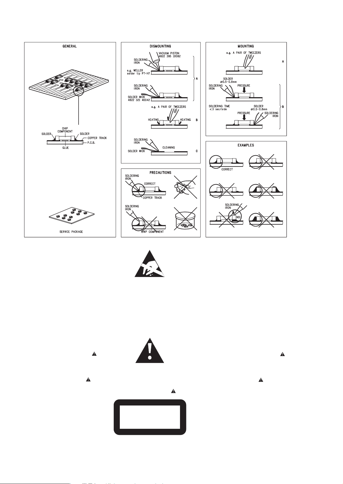
HANDLING CHIP COMPONENTS
1 - 1
© WARNING
All ICs and many other semiconductors are susceptible to
electrostatic discharges (ESD). Careless handling during
repair can reduce life drastically.
When repairing, make sure that you are connected with the
same potential as the mass of the set via a wristband with
resistance. Keep components and tools at this potential.
f ATTENTION
Tous les IC et beaucoup d´autres semi-conducteurs sont
sensibles aux décharges statiques (ESD). Leur longévite
pourrait être considérablement écourtée par le fait qu´aucune
précaution nést prise à leur manipulation.
Lors de réparations, s´assurer de bien être relié au même
potentiel que la masse de l´appareil et enfileer le bracelet
serti d´une résistance de sécurité.
Veiller à ce que les composants ainsi que les outils que l´on
utilise soient également à ce potentiel.
©
Safety regulations require that the set be restored to its
original condition and that parts which are identical with
those specified be used.
Safety components are marked by the symbol
f
Les normes de sécurité exigent que l`appareil soit remis
à l`état d`origine et que soient utilisées les pièces de
rechange identiques à celles spécifiées.
Les composants de sécurité sont marqués
d WARNUNG
Alle ICs und viele andere Halbleiter sind empfindlich
gegenüber elektrostatischen Entladungen (ESD).
Unsorgfältige Behandlung im Reparaturfall kann die
Lebensdauer drastisch reduzieren.
Sorgen Sie dafür, daß Sie im Reparaturfall über ein Pulsarmband mit Widerstand mit dem Massepotential des
Gerätes verbunden sind.
Halten Sie Bauteile und Hilfsmittel ebenfalls auf diesem
Potential.
d
Bei jeder Reparatur sind die geltenden Sicherheitsvorschriften zu beachten. Der Originalzustand des Gerätes
darf nicht verändert werden. Für Reparaturen sind Originalersatzteile zu verwenden.
Sicherheitsbauteile sind durch das Symbol markiert.
ESD
SAFETY
ñ WAARSCHUWING
Alle IC´s en vele andere halfgeleiders zijn gevoelig voor
electrostatische ontladingen (ESD).
Onzorgvuldig behandelen tijdens reparatie kan de levensduur
drastisch doen vermindern. Zorg ervoor dat u tijdens reparatie
via een polsband met weerstand verbonden bent met hetzelfde
potentiaal als de massa van het apparaat.
Houd componenten en hulpmiddelen ook op ditzelfde potentiaal.
i AVVERTIMENTO
Tutti IC e parecchi semi-conduttori sono sensibili alle scariche
statiche (ESD).
La loro longevità potrebbe essere fortemente ridatta in caso di
non osservazione della più grande cauzione alla loro
manipolazione. Durante le riparationi occorre quindi essere
collegato allo stesso potenziale che quello della massa
delápparecchio tramite un braccialetto a resistenza.
Assicurarsi che i componenti e anche gli utensili con quali si
lavora siano anche a questo potenziale.
ñ
Veiligheidsbepalingen vereisen, dat het apparaat in zijn
oorspronkeliijke toestand wordt teruggebracht en dat
onderdelen, identiek aan de gespecificeerde, worden toegepast.
De Veiligheidsonderdelen zijn aangeduid met het symbool
i
Le norme di sicurezza estigono che l´apparecchio venga
rimesso nelle condizioni originali e che siano utilizzati i
pezzi di ricambiago identici a quelli specificati.
Componenty di sicurezza sono marcati con
©
DANGER: Invisible laser radiation when open.
AVOID DIRECT EXPOSURE TO BEAM.
s Varning !
Osynlig laserstrålning när apparaten är öppnad och
spärren är urkopplad. Betrakta ej strålen.
∂ Advarsel !
Usynlig laserstråling ved åbning når sikkerhedsafbrydere
er ude af funktion. Undgå udsaettelse for stråling.
CLASS 1
LASER PRODUCT
ß Varoitus !
Avatussa laitteessa ja suojalukituksen ohitettaessa olet alttiina
näkymättömälle laserisäteilylle. Älä katso säteeseen !
©
After servicing and before returning the set to customer
perform a leakage current measurement test from all
exposed metal parts to earth ground, to assure no
shock hazard exists.
The leakage current must not exceed 0.5mA.
f
"Pour votre sécurite, ces documents doivent être utilisés par
des spécialistes agréés, seuls habilités à réparer votre
appareil en panne".

T
ECHNICAL SPECIFICATIONS
G
M
M
B
P
D
W
A
O
S
F
T
T
I
S
S
I
I
2 - 1
ENERAL
ains voltage -/00C/05 : 230 V
-/01/19
ains freq.. -/00C/05 : 50 Hz
-/01/19
attery main set : 9 V (R20, UM1 x 6)
remote : 3V (R03, AAA x 2)
ower consumption : < 35 W (max.)
imension (W x H x D) : 471 x 153 x 251 mm
eight : 3.8 Kg
: 120 / 230 V
-/17 : 120V
: 50 / 60 Hz
-/17 : 60 Hz
MPLIFIER
utput power mains : 2 x 1.6 W
battery : 2 x 1.6 W
peaker impedance : 2 x 4 ohm
requency response :
BASS - 100 Hz : +6 / -14 dB
MID - 1K Hz : +8 / -8 dB
HIGH - 10K Hz : +10 / -10 dB
DBB on : +8 dB
UNER - FM SECTION
SPECIFICATIONS
TUNER - AM SECTION
Tuning range MW : 531 - 1602 kHz
-/17 : 530 - 1700 kHz
LW : 153 - 279 kHz
IF frequency : 450 kHz ± 1 kHz
Sensitivity MW : 3200 µV/m at 26dB S/N
LW : 5500 µV/m at 26dB S/N
Selectivity MW : 22 dB
LW : 29 dB
IF rejection MW : 64 dB
LW : 60 dB
Image rejection MW : 32 dB
LW : 38 dB
AUDIO CASSETTE RECORDER
Number of tracks : 1 stereo
Tape speed : 4.76 cm/sec ± 3%
Wow & flutter : < 0.48 JIS UWTD
Fast wind/rewind C60 : < 110 sec.
Frequency response P/B : 125 - 8000 Hz
S/N ratio : > 36 dB (R/P)
Erasing ratio : > 50 dB
Bias frequency : 73 ± 1.5 kHz
uning range : 87.5 - 108 MHz
F frequency : 10.7 MHz ± 0.2 MHz
ensitivity : 20 dBf at 26dB S/N
electivity : 24 dB at 300kHz
F rejection : 85 dB
mage rejection : 24 dB
COMPACT DISC
Frequency response : 100 Hz - 10 kHz ± 2dB
S/N ratio : 60 dB
Channel difference 1 kHz : 2 dB
Channel crosstalk 1 kHz : 40 dB
Laser wavelength : 780 ± 20 nm
Laser light power : < 0.5 mW
SERVICE TOOLS
Audio signal disc SBC 429.......................................................................4822 397 30184
Playability test disc SBC 444
Test disc 5 (disc without errors ) +
Test disc 5A (disc with dropout errors, black spots and fingerprints)
SBC 426/426A.....................................................................4822 397 30096
Burn in test disc (65 min. 1kHz signal at -30 dB level without “pause”)
...................................................................4822 397 30245
.....4822 397 30155
AVAILABLE ESD PROTECTION EQUIPMENT
anti-static table mat
anti-static wristband
connection box (3 press stud connections, 1MΩ) 4822 320 11307
extendible cable (2m, 2MΩ, to connect wristband to connection box) 4822 320 11305
connecting cable (3m, 2MΩ, to connect table mat to connection box) 4822 320 11306
earth cable (1MΩ, to connect any product to mat or to connection box) 4822 320 11308
KIT ESD3 (combining all 6 prior products - small table mat) 4822 310 10671
wristband tester 4822 344 13999
large 1200x650x1.25mm 4822 466 10953
small 600x650x1.25m 4822 466 10958
4822 395 10223
2 - 2
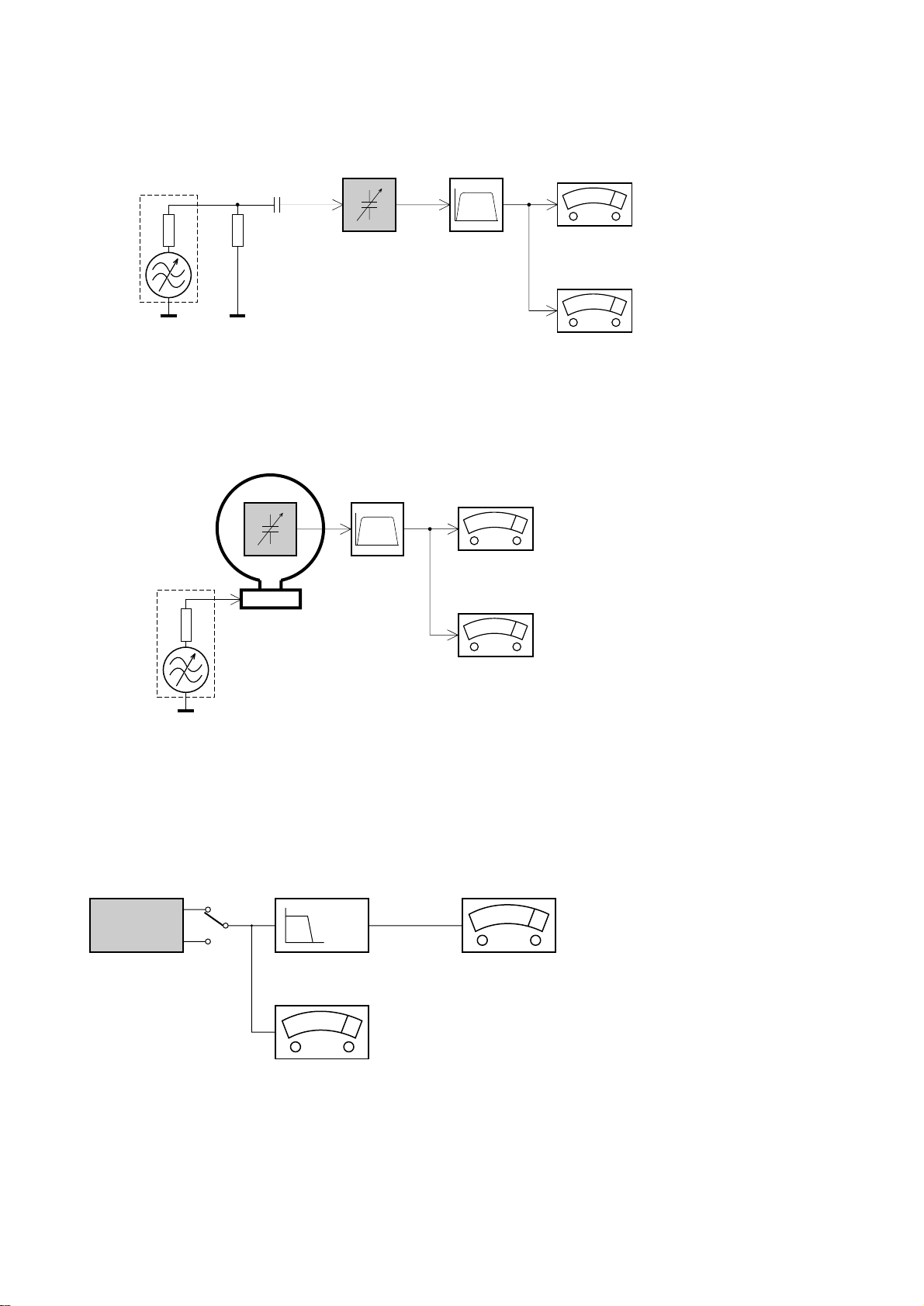
SERVICE MEASUREMENT
Bandpass
250Hz-15kHz
e.g. 7122 707 48001
LF Voltmeter
e.g. PM2534
DUT
RF Generator
e.g. PM5326
S/N and distortion meter
e.g. Sound Technology ST1700B
Tuner SW
To avoid atmospheric interference all AM-measurements have to be carried out in a Faraday«s cage.
Use a bandpass filter (or at least a high pass filter with 250Hz) to eliminate hum (50Hz, 100Hz).
Ri=50Ω
Aerial replacement
Capacitor
R=50Ω
Bandpass
250Hz-15kHz
e.g. 7122 707 48001
LF Voltmeter
e.g. PM2534
DUT
S/N and distortion meter
e.g. Sound Technology ST1700B
Frame aerial
e.g. 7122 707 89001
Tuner AM (MW,LW)
To avoid atmospheric interference all AM-measurements have to be carried out in a Faraday«s cage.
RF Generator
e.g. PM5326
Ri=50Ω
Low pass filter 22kHz
L
R
LEVEL METER
e.g. Sennheiser UPM550
with FF-filter
S/N and distortion meter
e.g. Sound Technology ST1700B
DUT
CD
Use Audio Signal Disc SBC429 4822 397 30184 (replaces test disc 3)
L.P.F. = 13
th
order filter 4822 395 30204
3 - 1
C
D
R
E
W
R
I
T
A
B
L
E
C
D
S
O
U
N
D
M
A
C
H
I
N
E
CD SYNCHR
O STAR
T RECORDING
R
EC
O
RD
POWER
BASS
PROG
MODE
R
E
M
O
T
E
S
E
N
S
O
R
VOLUME
HIGH
MID
S
O
U
R
C
E
30 P
R
E
SE
T
D
IG
IT
A
L
T
U
N
ER
BAND
DIG
IT
AL
DY
N
AMIC BA
SS BOO
ST
PRESET
DO
W
N
PRESET
UP
PL
AY
SEARCH
ST
OP/OPE
N
PA
U
SE
See A
8
07 9
!@#65
$
%^
321 4
V
O
L
U
M
E
SE
A
R
C
H
PRESE
T
T
U
N
IN
G
REPE
AT
SH
UFF
L
E
S
EA
R
C
H
1
9
8
6
7
2
4
3
5
Remote control
for AZ2055 model only
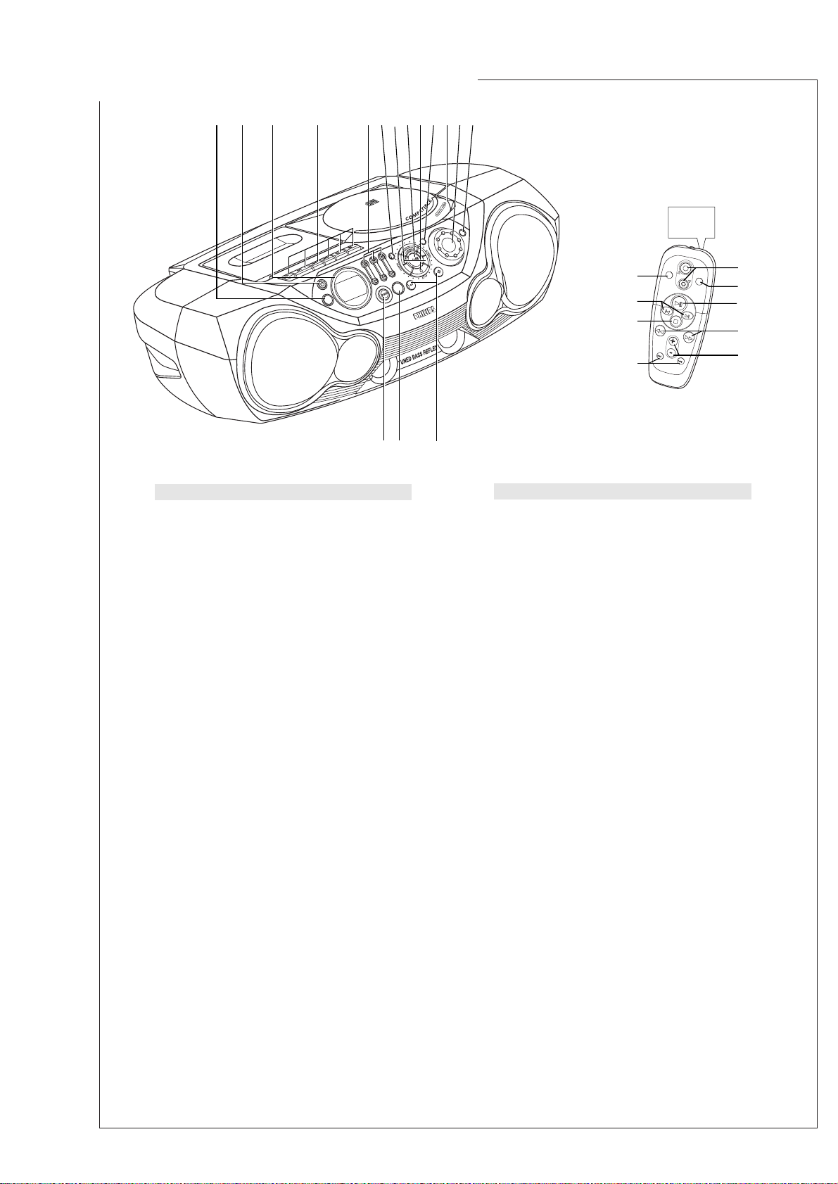
TOP AND FRONT PANELS
(See 1)
1SOURCE – selects CD/ TUNER / TAPE function
2y – power on/ off switch
3Display – shows the status of the set
4
Cassette recorder keys
RECORD 0 – starts recording
PLAY 2 – starts playback
SEARCH 5/6 – fast winds/rewinds tape
STOP/OPEN 9/
– opens the cassette compartment
– stops the tape
PAUSE ; – pauses playback or recording
5BASS, MID, HIGH – EQ keys to adjust the bass,
mid & treble frequencies
6PROG
CD:
programs tracks and reviews the program;
Tuner:
programs preset radio stations
Navigation controls
7 , §
§
§
CD:
– searches back and forward within a
track;
– skips to the beginning of a current
track/previous/ later track
Tuner:
– tunes to radio stations
(down, up)
.
82; – starts or pauses CD playback
99 – stops CD playback;
– erases a CD program
0MODE – selects different play modes:
e.g. REPEAT or SHUFFLE (random) order
!PUSH TO OPEN – opens/closes the CD door
@VOLUME – to adjust volume level
#REMOTE SENSOR
(for AZ2055 model only)
–
infrared sensor for remote control
$PRESET DOWN/ UP (–, +) – selects a preset
tuner station
(down, up)
%BAND – selects waveband
^DBB – (Dynamic Bass Boost) activates a more
vivid bass response
REMOTE CONTROL
(for AZ2055 only)
1VOLUME 3,4 – adjusts volume level
(up, down)
2SHUFFLE – plays all CD tracks in random order
32; – starts/ pauses CD playback
4SEARCH 5, 6 – searches backwards/ forwards
within a track
5PRESET +, – – selects a preset radio station
(up, down)
6TUNING , § – tunes to tuner stations
(down, up)
79 – stops CD playback;
– erases a CD program
8¡, ™ – skips to the beginning of a current track
previous/ subsequent track
9REPEAT – repeats a track /program/ entire CD
CAUTION
Use of controls or adjustments or performance of
procedures other than herein may result in hazardous
radiation exposure or other unsafe operation.
CONNECTIONS AND CONTROLS
3 - 2
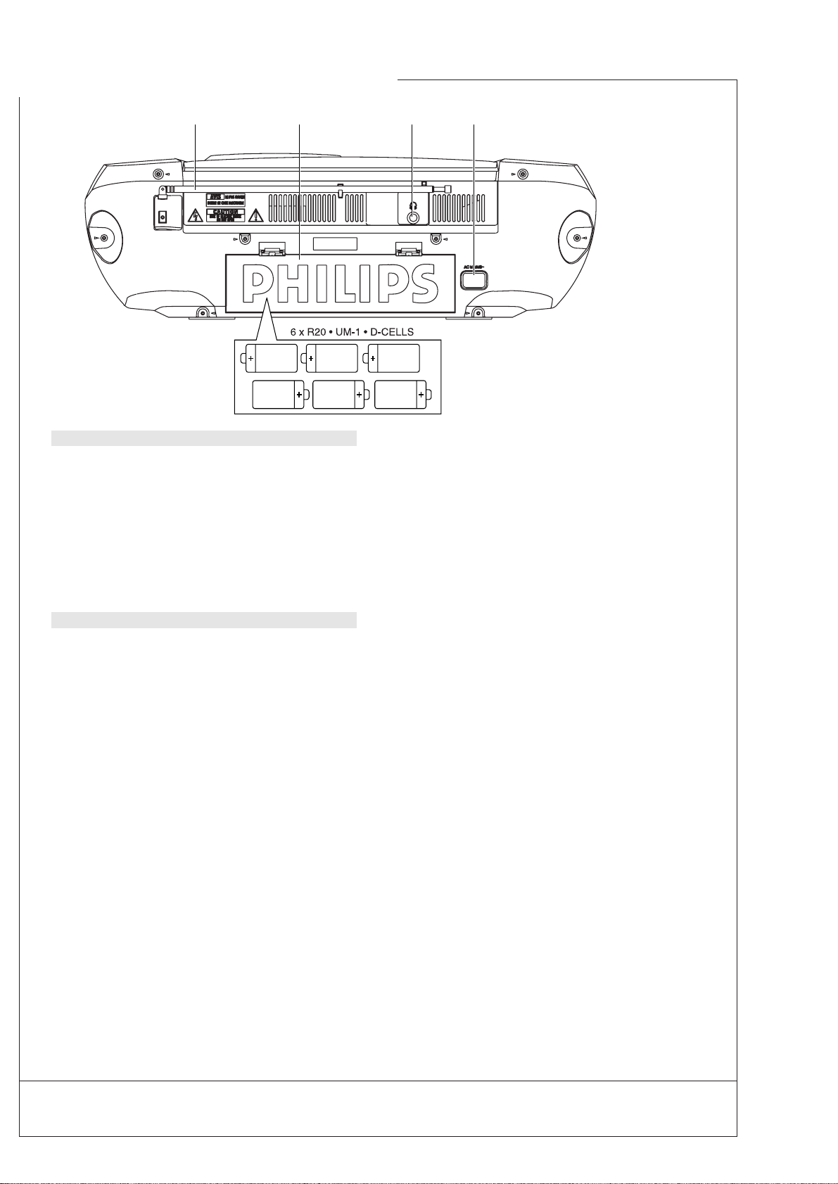
Batteries
(not included)
•Insert 6 batteries, type R-20, UM-1 or D-cells,
(preferably alkaline) with the correct polarity.
Remote control
(for AZ2055 only /See A)
• Insert 2 batteries, type AAA, R03 or UM4
(preferably alkaline).
Incorrect use of batteries can cause electrolyte
leakage and will corrode the compartment or cause
the batteries to burst.
•
Do not mix battery types:
e.g. alkaline with carbon
zinc. Only use batteries of the same type for the
set.
•When inserting new batteries, do not try to mix old
batteries with the new ones.
•
Batteries contain chemical substances,
so they should be disposed of properly.
Using AC Power
1
Check if the power supply, as shown on the type
plate located on the bottom of the set,
corresponds to your local power supply. If it does
not, consult your dealer or service center.
2
If your set is equipped with a voltage selector,
adjust the selector so that it matches with the
local power .
3
Connect the power cord to the wall outlet.
4
To disconnect the power supply, unplug the set
from the wall outlet.
Auto-Standby mode
When a CD or tape has reached the end of playback
and remains in the stop position for more than
15 minutes, the set will switch off automatically to
save energy.
The type plate is located on the bottom of the
set.
BACK PANEL
&Telescopic antenna – improves FM reception
*Battery compartment – for 6 batteries,
type R-20, UM1 or D-cells
(p – 3.5 mm stereo headphone jack
Note: The speakers will be muted when
headphones are connected to the set.
)AC MAINS – inlet for power cord
POWER SUPPLY
Whenever convenient, use the power supply to
conserve battery life. Make sure you remove the
power plug from the set and wall outlet before
inserting batteries.
& * ()
CONNECTIONS AND CONTROLS
For more information on operation instruction please visit Philips Audio internet site :
http://www.audio.philips.com
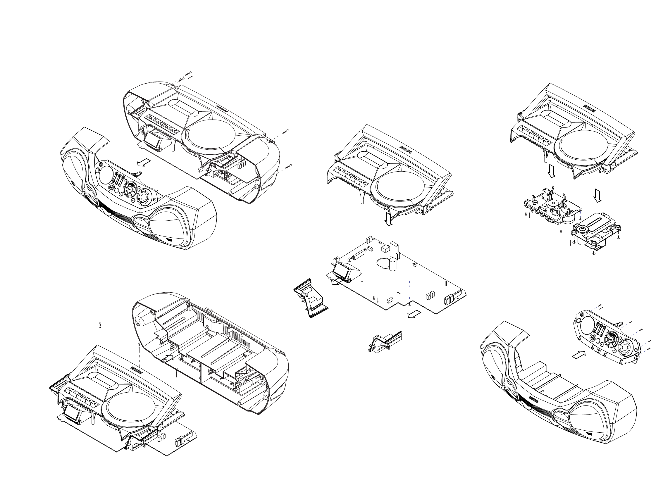
A2
B3(x3)
A1 (x9)
C4 (x2)
C5 (x4)
D6 (x4)
D7 (x4)
E8 (x6)
A. REMOVE FRONT CABINET ASSEMBLY
- REMOVE SCREWS A1 (3X20) 9 PCS.
- REMOVE SCREW A2 (3X10) 1 PC
(INSIDE CD DOOR)
E. REMOVE CD PANEL-FRONT ASSEMBLY
- REMOVE SCREWS E8 (2.5X10) 6 PCS.
B. REMOVE BACK CABINET ASSEMBLY.
- REMOVE SCREWS B3 (3X10) 3 PCS.
C. REMOVE COMBI BOARD ASSEMBLY
- REMOVE SCREWS C4 (3X10) 2 PCS.
- REMOVE FIXING BRACKETS
- REMOVE SCREWS C5 (3X10) 4 PCS.
D. REMOVE DECK MECHANISM
- REMOVE SCREWS D6 (3X8) 4 PCS.
- REMOVE CASSETTE DECK
- REMOVE SCREWS D7 (2.5X10) 4 PCS.
- REMOVE CD DECK
4 - 14 - 1
DISASSEMBLY DIAGRAM

4 - 2 4 - 2
STOP button pressed in any step returns
to begin of Service Testprogram.
HIGH-UP button
pressed?
Y
Y
Display shows all
segments and flags.
see figure 1
Display shows part
segments and flags.
see figure 2
Display shows part
segments and flags.
see figure 3
DISPLAY TEST
CD SERVO TEST
Display shows
version number
of the P - software.
NEXT button
pressed?
Display shows
see table 1
NEXT button
pressed?
BASS-UP button
pressed?
BASS-DN button
pressed?
MID-DN button
pressed?
MID-UP button
pressed?
Slide moves
outside as long as
button is held
depressed.
Slide moves
inside as long as
button is held
depressed.
Y
Y
Y
Y
Y
N
NN
N
N
FOCUS found?
Y
N
Display shows
objective moves up&down
disc motor for 160ms "on"
STOP button
pressed?
Y
STOP button
pressed?
Y
N
Display shows
disc motor turns.
FOCUS search
SLIDE MOTOR test DISC MOTOR test
To enter CD Service
Testprogramm hold
PROG & MODE buttons
depressed while pressing
POWER on. Press
SOURCE to select
TUNER mode.
To enter CD Service
Testprogramm hold
PROG & MODE buttons
depressed while pressing
POWER on. Press
SOURCE to select
CD mode.
*
*
*
To leave Service Testprogram press POWER to
switch off.
Door switch is ignored → CD door can be opened.
Slide servo, Radial servo, Focus servo, Disc motor
and Laser are switched off.
Mute is switched on via decoder IC.
*
Volume up/down buttons function independentely
of the service testprogram.
N
N
HIGH-UP button
pressed?
Y
N
HIGH-UP button
pressed?
Y
N
N
Display shows
version number
of the P - software.
Y
table 3
N
PROG button
pressed?
Ser. preset frequencies
acc. table 3 are copied
to the RAM.
Tuner is normal working
STOP button
pressed?
N
Y
SERVICE PRESET FREQUENCIES
1)
How to set frequency grid:
AM - 9 kHz / FM - 50 kHz : Hold MODE with the PRESET DOWN simultaneously and then switch to TUNER.
AM - 10 kHz / FM - 100 kHz : Hold MODE with the PRESET UP simultaneously and then swutch to TUNER.
Selected frequency grid is stored in the EEPROM.
CD TEST
TUNER TEST
Disc motor turns
clockwise
as long as button
is held depressed.
(accelerate)
Disc motor turns
counter clockwise
as long as button
is held depressed.
(brake)
-02
FOC
CD V-02
HIGH-DN button
pressed?
Y
N
Display shows
EP
E2prom clear
STOP button
pressed?
N
Y
EP2PROM CLEAR
FM
REGION
EUROPE
EUROPE2B OVERSEAS EAST-EUROPE USA
FM/MW/LW
FM/MW FM/MW FM/MW FM/MW
1)
Grid switchable
10-100kHz/9-50kHz
PRESET
/00/05/20/25
/00 /01/21 /14
/14/17/37
1 87.5 MHz
87.5 MHz 87.5 MHz 65.81 MHz 87.5 MHz
2 108 MHz
108 MHz 108 MHz 108 Mhz 108 MHz
3 531 kHz
531 kHz 531/530 KHz 74 MHz 530 kHz
4 1602 kHz
1602 kHz 1602/1700 kHz 87.5 MHz 1700 kHz
5 558 kHz
558 kHz 558/560 kHz 531 kHz 560 kHz
6 1494 kHz
1494 kHz 1494/1500 kHz 1602 kHz 1500 kHz
7 153 kHz
--558 kHz -
8 279 kHz
--1494 kHz -
9 198 kHz
----
10 -
----
11 -
----
12 -
----
13
-
----
TU V-02
Y
N
BAND button
pressed?
Display shows the
version of ECO6 tuner
according to table 4.
STOP button
pressed?
N
Y
PLAY button
pressed?
SERVICE PLAY TEST
Set is in Service PLAY Mode.
The Service Play Model
is intended to detect and
identify the failures in the
CD Mode.
In this mode the electronics
will still function even when
an error is detected so that
repair activities can be carried out.
In case of failures, error
codes according to table 2
will be displayed.
Error code Error description
Err 1
No Focus found.
Err 6
Radial error on search mode.
Subcode error on play mode.
Err 3
Focus error during tracking initialization.
Err 2
Time out error for disc motor reach the normal speed.
CD ERROR CODES
table 2figure 2
figure 1
figure 3
table 1
Err 5
Focus error on play mode.
Err 7
Focus error
Err 4
OPEN
Door switch is open.
Inner switch is opened.
- 1
Inner switch is closed.
CLOS
Door switch is closed.
VERS REGION
01
/00 EUROPE - 3 BAND
/14 EAST EUROPE
10
/01 OVERSEAS
06
/00 EUROPE - 2 BAND
TUNER VERSION
table 4
17
/17 USA
14
+ 1
DBB
LWMWFMAM
all
program
shuffle
stereo
repeat
LWAM
all
shuffle
stereo
DBB
MWFM
program
repeat
SERVICE TEST PROGRAM

4 - 34 - 3
Abbreviations and Pin-description of CD Ics
SERVO PROCESSOR SAA7325H
SYMBOL PIN DESCRIPTION
HFREF 1 comparator common mode input
HFIN 2 comparator signal input
ISLICE 3 current feedback output from data slicer
V
SSA1
4
(1)
analog ground 1
V
DDA1
5
(1)
analog supply voltage 1
I
ref
6 reference current output pin
V
RIN
7 reference voltage for servo ADC’s
D1 8 unipolar current input (central diode signal input)
D2 9 unipolar current input (central diode signal input)
D3 10 unipolar current input (central diode signal input)
D4 11 unipolar current input (central diode signal input)
R1 12 unipolar current input (satellite diode signal input)
R2 13 unipolar current input (satellite diode signal input)
V
SSA2
14
(1)
analog ground 2
CROUT 15 crystal/resonator output
CRIN 16 crystal/resonator input
V
DDA2
17
(1)
analog supply voltage 2
LN 18 DAC left channel differential output - negative
LP 19 DAC left channel differential output - positive
V
neg
20 DAC negative reference input
V
pos
21 DAC positive reference input
RN 22 DAC right channel differential output - negative
RP 23 DAC right channel differential output - positive
SELPLL 24 selects whether internal clock multiplier PLL is used
TEST1 25 test control input 1; this pin should be tied LOW
CL16 26 16.9344 MHz system clock output
DATA 27 serial d4(1)ata output (3-state)
WCLK 28 word clock output (3-state)
SCLK 29 serial bit clock output (3-state)
EF 30 C2 error flag output (3-state)
TEST2 31 test control input 2; this pin should be tied LOW
KILL 32 kill output (programmable; open-drain)
V
SSD1
33
(1)
digital ground 2
V2/V3 34 versatile I/O: input versatile pin 2 or output versatile pin 3 (open-drain)
WCLI 35 word clock iutput (for data loopback to DAC)
SDI 36 serial data input (for data loopback to DAC)
SCLI 37 serial bit clock input (for data loopback to DAC)
RESET 38 power-on reset input (active LOW)
SDA 39 microcontroller interface data I/O line (open-drain output)
SCL 40 microcontroller interface clock line input
Abbreviations and Pin-description of CD Ics
SERVO PROCESSOR SAA7325H
SYMBOL PIN DESCRIPTION
RAB 41 microcontroller interface R/W and load control line input (4-wire bus mode)
SILD 42 microcontroller interface R/W and load control line input (4-wire bus mode)
STATUS 43 servo interrupt request line/decoder status register output (open-drain)
TEST3 44 test control input 3; this pin should be tied LOW
RCK 45 subcode clock input
SUB 46 P-to-W subcode bits output (3-state)
SFSY 47 subcode frame sync output (3-state)
SBSY 48 subcode block sync output (3-state)
CL11/4 49 11.2896 MHz or 4.2336 MHz (for microcontroller) clock output
V
SSD2
50
(1)
digital ground 3
DOBM 51 bi-phase mark output (externally buffered; 3-state)
V
DDD1(P)
52
(1)
digital supply voltage 2 for periphery
CFLG 53 correction flag output (open-drain)
RA 54 radial actuator output
FO 55 focus actuator output
SL 56 sledge control output
V
DDD2(C)
57
(1)
digital supply voltage 3 for core
V
SSD3
58
(1)
digital ground 4
MOTO1 59 motor output 1; versatile (3-state)
MOTO2 60 motor output 2; versatile (3-state)
V4 61 versatile output pin 4
V5 62 versatile output pin 5
V1 63 versatile intput pin 1
LDON 64 laser drive on output (open-drain)
Note : All supply pins must be connected to the same external power supply voltage.
Abbreviations and Pin-description of CD ICs Abbreviations and Pin-description of CD ICs
5 - 1 5 - 1
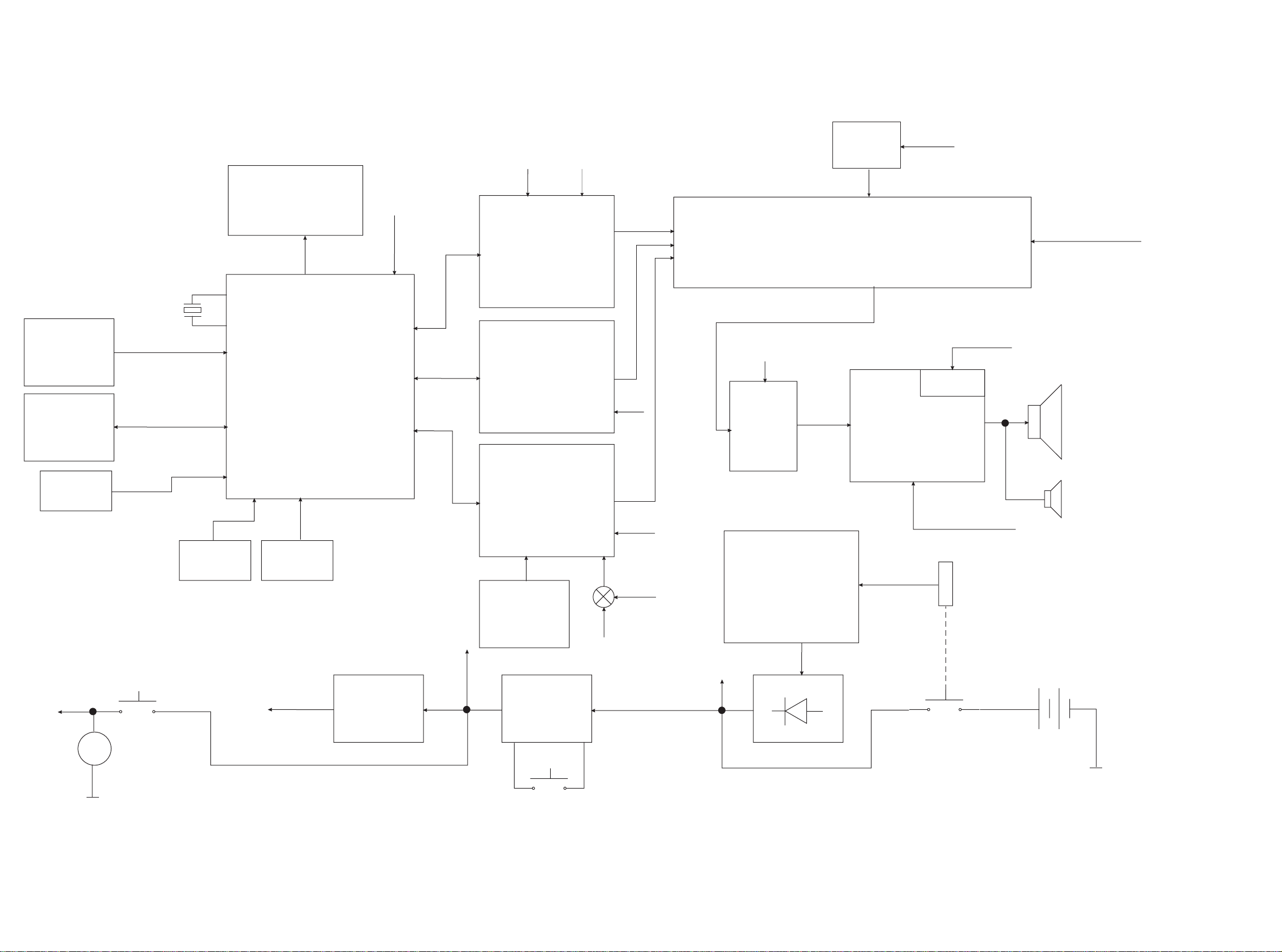
4.19MHz
CD99
LAYOUT
CELL
ECO MTF
LAYOUT
CELL
ECO6
LAYOUT
CELL
LCD DISPLAY
DA11
CD DRIVE
EEPROM
REMOTE
SENSOR
TMP86CH21
Xformer
AC IN
Keys
CD Door
SW
Vol.
Encoder
5.6V
V. Reg.
Mute
Ctrl
Mute
Power
Amp.
A_on
+A
+A
Tape
Power On
AC Socket
SW
CPU
CPU
A_on
+A_on
Battery 9V
L/R
L/R
L/R
M
I2CSound Processor with Source Selector,
3 Bands EQ, DBB and ALC
Power
On/Off
ckt
+B
CPU
+B
+M
+M
+B
+B
+B
*Optional
+B
+
-
Buzzer
Speaker
Ripple
Filter
BLOCK DIAGRAM
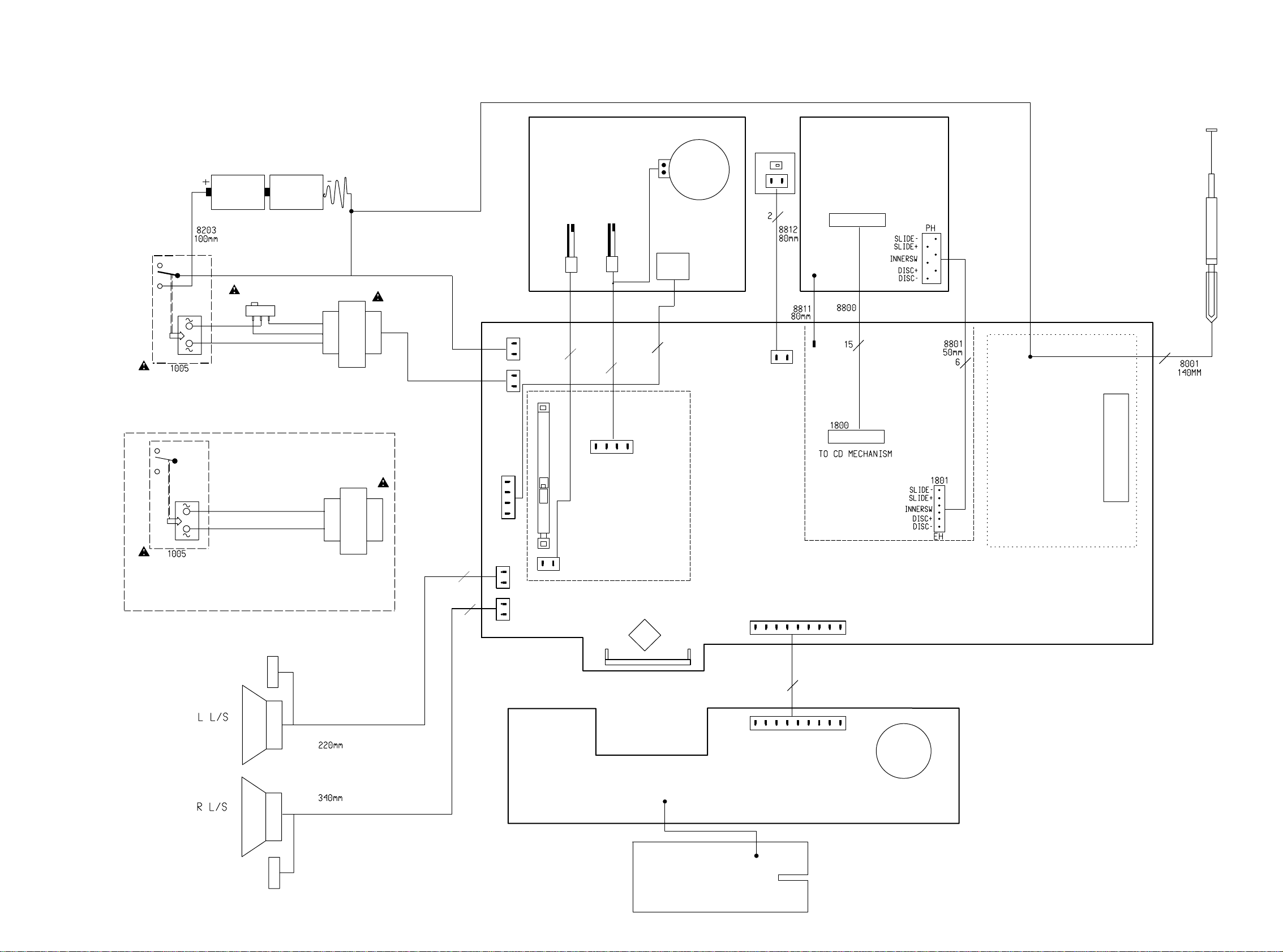
5 - 25 - 2
15
BATTERIES
TRANSFORMER
4 OHM
1008
1010
1007
1009
PIEZO
ECO-MTF Layout cell
9
1404
FOR
GND
R
GND
SECONDARY
8401
8204
CELL
4
4
2
6
15
1
SWITCH
9V BATTERY
ORANGE
FOR
TRANSFORMER
65MM
110-127V
BLUE
ON/OFF SW
1
LAYOUT CELL
LAYOUT
4 OHM
1
CD99
LCD
PLAY SW
TAPE MECHANISM
MECHANISM
AD
220-240V
ECO6
PIEZO
L
SHIELD
8402
8802
MAINS SOCKET
8202
1006
1011
1006
BLACK
9
MAINS SOCKET
/01,/11,/19
VOLTAGE SELECTOR
/13,/16,/17
8201
8206
2
2
220MM
8702
8701
8703
/00,/05,/10,
COMBI BOARD
CD
KEYBOARD_PCB
CD DOOR
TUNER
MOTOR
REC/PLAY HEAD
ROTARY ENCODER
CPU
1
2
FE-ST-VK-N
1519
12345678
89
1711
EH-B
1
2
1256
EH-B
1
2
FE-BT-VK-N
1401
1234567
3
4
PH-B
1700
1
2
3
4
1251
EH-B
1403
DIPMATE
12
EH-B
1725
1
2
1253
PH-B
1
2
1402
EH-B
12
1252
PH-B
1
2
WIRING DIAGRAM
 Loading...