

philips AZ 1141, AZ 1142, AZ 1143, AZ 1145 Service Manual
CD Stereo Radio Recorder
AZ1140
AZ1141
AZ1142
AZ1143
AZ1145
all versions
TABLE OF CONTENTS
chapter
Handling chip components and safety 1 - 1
Technical Specification & Service Tools 2 - 1
Service Measurement 2 - 2
Connections & Controls
Instructions for use
Disassembly Diagram 4 - 1
CD Service Test Program 4 - 2 to 4 - 3
Block Diagram
Wiring Diagram 6 - 1
CONTROL BOARD
circuit diagram
layout diagram
SWITCH & VOLUME BOARD
layout diagram
TUNER BOARD
circuit diagram
layout diagram
..................................................
................................................
.................................................
...................................................
........................................
.............................................................
...........................................................
...................................................
.......................................................
.......................................................
.......................................................
.......................................................
.............................
..........................
3 - 1
3 - 2 to 3 - 6
5 - 1
7 - 1, 7 - 3
7 - 2
8 - 1
9 - 1
9 - 2
MAIN BOARD
circuit diagram
layout diagram
RECORDER & BEAT CUT BOARD
circuit diagram
layout diagram
CD MODULE
circuit diagram
layout diagram
EXPLODED VIEWS DIAGRAM
cabinet
tape deck
Mechanical partslist
Electrical partslist
.......................................................
.......................................................
.......................................................
.......................................................
.......................................................
.......................................................
.................................................................
............................................................
.....................................................
...............................................
chapter
10 - 1
10 - 2
11 - 1
11 - 2
12 - 2
12 - 1
13 - 1
13 - 2
13 - 2
14 - 1 to 14 - 4
Safety regulations require that the set be restored to its original
condition and that parts which are identical with those specified
be used.
C
Copyright 1995 Philips Consumer Electroncis B.V. Eindhoven, The Netherlands
All rights reserved. No part of this publication may be reproduced, stored in a retrieval
system or transmitted, in any form or by any means, electronic, mechanical, photocopying,
or otherwise without the prior permission of Philips.
Printed in The Netherlands Copyright reserved Subject to modification
PCS 104 409
CLASS 1
LASER PRODUCT
GB
3140 785 22260Published by SS 0024 Service Audio

TECHNICAL SPECIFICATIONS
2-1
GENERAL
Mains voltage -/00 : 230 V
-/01/11/16 : 120/230 V
-/05/10 : 240 V
-/17 : 120 V
Mains frequency -/00/05/10 : 50 Hz
-/01/11/16 : 50 / 60 Hz
-/17 : 60 Hz
Battery mains : 9 V (R14 x 6)
Remote : 3V (R03 x 2)
Power consumption normal : 10 W
standby : 2 W
Dimension (W x H x D) : 290 x 152 x 253 mm
Weight : 2.6 Kg
AMPLIFIER
Output power mains : 2 x 1.6 W
battery : 2 x 2 W
Speaker impedance : 2 x 4 ohm
Frequency response : 100 Hz - 8 kHz (±3dB)
TUNER - FM SECTION
TUNER - AM SECTION
Tuning range MW : 531 - 1602 kHz
-/17 : 520 - 1730 kHz
LW : 153 - 279 kHz
IF frequency : 450 kHz ± 1 kHz
Sensitivity MW : 64 dBu at 26dB S/N
LW : 70 dBu at 26dB S/N
Selectivity MW : 22 dB
LW : 29 dB
IF rejection ratio MW : 70 dB
LW : 70 dB
Image rejection ratio MW : 32 dB
LW : 35 dB
AUDIO CASSETTE RECORDER
Tape speed accuracy : ± 3%
Wow & flutter : < 0.35 % JIS WTD
Fast wind/rewind C60 : < 120 sec.
Frequency response P/B : 125 – 6.3 kHz
S/N ratio : 45 dB
COMPACT DISC
Tuning range : 87.5 - 108 MHz
IF frequency : 10.7 MHz ± 0.2 MHz
Sensitivity : 16 dBf at 26dB S/N
Selectivity : 55 dB at ± 300kHz
IF rejection : 85 dB
Image rejection : 40 dB
Frequency response : 100 Hz - 10 kHz
S/N ratio : > 50 dB
Channel difference 1 kHz : < 3 dB
Channel crosstalk 1 kHz : > 26 dB
Laser wavelength : 780 ± 20nm
Laser light power : < 0.3 mW
SERVICE TOOLS
Audio signal disc SBC 429.......................................................................4822 397 30184
Playability test disc SBC 444
Test disc 5 (disc without errors ) +
Test disc 5A (disc with dropout errors, black spots and fingerprints)
SBC 426/426A.....................................................................4822 397 30096
Burn in test disc (65 min. 1kHz signal at -30 dB level without “pause”)
Universal test cassette Fe SBC 420........................................................4822 397 30071
...................................................................4822 397 30245
.....4822 397 30155
PCS 104 410
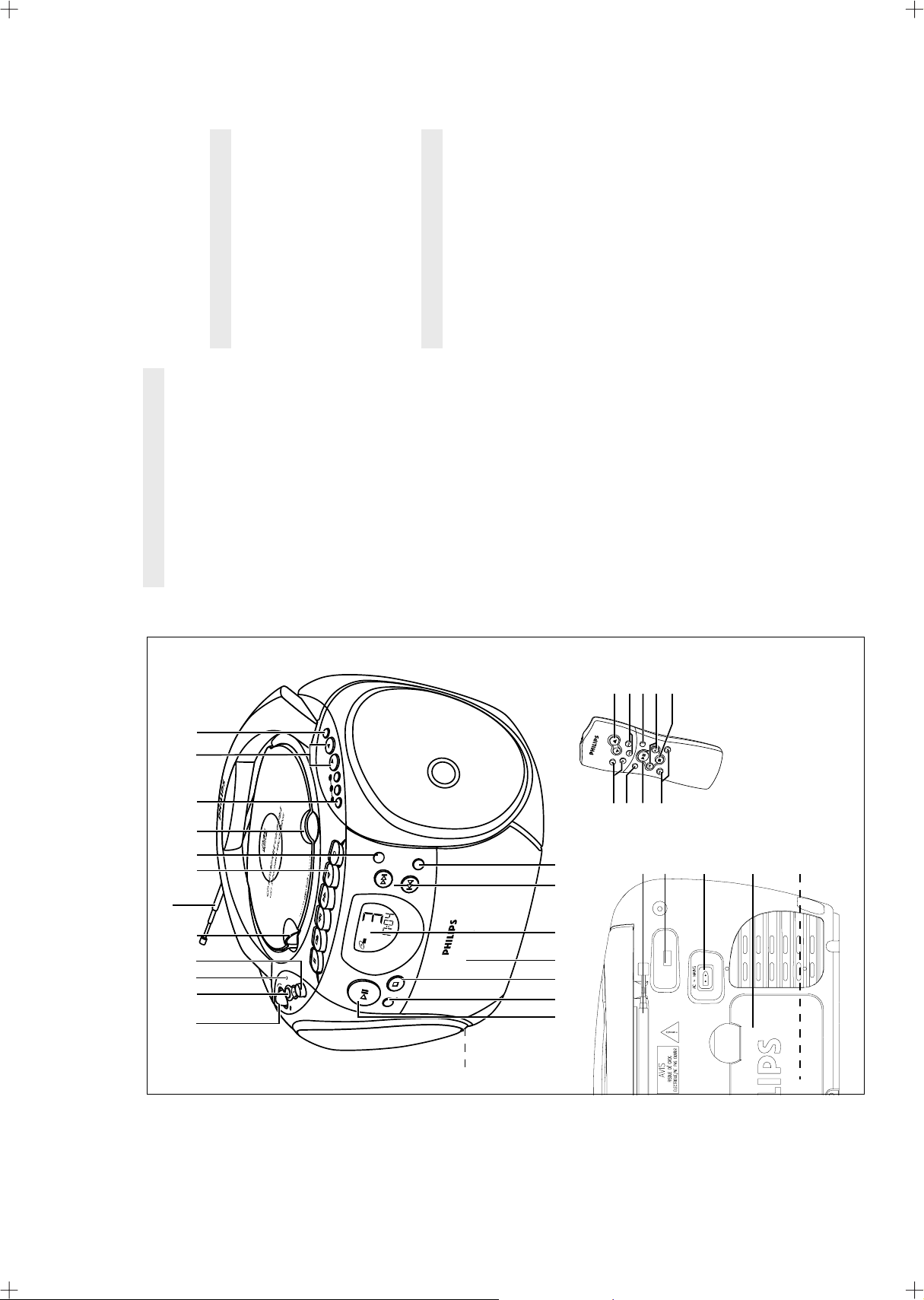
CONNECTIONS AND CONTROLS
and reviews the
tracks
whistle tones during
MW (AM) recordings
3-1
stations
radio station
forwards within a track/CD
programme
Tuner - programmes preset radio stations;
CD - programmes
& PROGRAM -
TOP AND FRONT PANELS
1 POWER slider - selects the sound source
BACK PANEL
OFF and also switches
for CD/ TUNER/ TAPE
the set off
2 VOL +, – - adjusts the volume level
type R-14, UM-2 or C-cells
* p - 3.5 mm stereo headphone socket
( Telescopic aerial - improves FM reception
) BEAT CUT switch - eliminates possible
¡ AC Mains - inlet for mains lead
™ Battery compartment - for six batteries,
£ Voltage selector (located inside the battery
the bass
- fast winds/rewinds the tape
is running low
3 BATT LOW - indicates when battery power
4 DBB (Dynamic Bass Boost) - enhances
5 OPEN•CLOSE - opens/ closes the CD door
/ 6
STOP•OPEN 9/ - stops the tape;
SEARCH 5
RECORD 0 - starts recording
PLAY 1 - starts playback
6 CASSETTE RECORDER keys
VOLUME 3,4 – adjusts volume level
PRESET 3,4 (up, down) – selects a preset
TUNING ∞, § (down, up) – tunes to radio
compartment. Some versions only) - select
the correct local voltage 110/220 V before
plugging in the set
REMOTE CONTROL
1
2
compartment
- opens the cassette
remote control
SHUFFLE – to play CD tracks in random order5REPEAT – repeats a track/ CD programme/
3
4
tuner stations
CD playback
three radio stations
PAUSE ; - interrupts recording or playback
7 Remote sensor - infrared sensor for the
8 1-3 - programmes and selects your favourite
9 PRESET 3, 4 - (down, up) selects preset
0 BAND - selects waveband
! PLAY PAUSE 2; - starts /pauses
entire CD
interrupts CD playback
2; – starts and pauses CD playback/
6
e.g. SHUFFLE/ REPEAT CD
tracks or programme in random
@ CD MODE - selects a different play mode
CD programme
track/ previous/ later track
¡, ™ – skips to the beginning of a current
STOP 9 – stops CD playback or erases a
SEARCH 5, 6 – searches backwards or
7
8
9
/repeated order
programme;
activates/ deactivates display
demo mode.
# STOP 9 - stops CD playback or erase a CD
18573
/ §
searches back and forward within a
track;
- skips to the beginning of a current
Tuner: (down, up) tunes radio stations.
CD: -
$ Cassette door
% Display - shows the status of the set
^ SEARCH ∞
track/ previous/ later track
CAUTION
Use of controls or adjustments or performance of procedures other than herein
may result in hazardous radiation exposure or other unsafe operation.
(
98 0
3
2 67 55
1 4
BAND
PRESET
3
2
1
REMOTE
REMOTE
SENSOR
SENSOR
RECORD
PLAY
SEARCH
CD
ALL
REPEAT
PROGRAM
STOP•OPEN
PAUSE
VOL
TUNER
BATT
LOW
DBB
CD
BASS
PLAY•PAUSE
DYNAMIC
BOOST
TAPE
OFF
CD MODE
PROGRAM
SEARCH
AZ1145
CD RADIO CASSETTE R ECORDER
DIGITAL TUNER
DYNAMIC BASS BOOST
STOP
&^@ # $ %!
REPEAT
TUNING
VOLUME
PRESET
2
SEARCH
ontrol
C
STOP
emote
SHUFFLE
R
SEARCH
igital
D
694
(
)
¡
™
£
*
PCS 104 411
INSTRUCTIONS FOR USE
AC ~ MAINS
6 x R14 • UM-2 • C-CELLS
PROGRAM
REPEAT
ALL
CD
PLAY
•
P
AUSE
PAUSE
STOP
•
OPEN
SEARCH
PLAY
RECORD
DYNAMIC
BASS
BOOST
DBB
VOL
TUNER
BATT
LOW
CD
TAPE
OFF
REMOTE
SENSOR
PROGRAM
REPEAT
ALL
CD
PLAY
•
P
AUSE
PAUSE
STOP
•
OPEN
SEARCH
PLAY
RECORD
DYNAMIC
BASS
BOOST
DBB
VOL
TUNER
BATT
LOW
CD
TAPE
OFF
REMOTE
SENSOR
PROGRAM
REPEAT
ALL
CD
SEARCH
STOP
CD MODE
PLAY
•
P
AUSE
PAUSE
STOP
•
OPEN
SEARCH
PLAY
RECORD
DYNAMIC
BASS
BOOST
DBB
PROGRAM
REMOTE
SENSOR
3-2
.
TUNER or TAPE/OFF.
TAPE/OFF position and the keys on the tape deck are released.
Switching on and off
• Adjust the POWER slider to the desired sound source: CD,
• The set is switched off when the POWER slider is in the
™The volume and tuner presets will be retained in the set's
memory.
Adjusting volume and sound
1. Press the VOL +, – controls to increase or decrease VOLUME
(or press 3 or 4on the remote control).
demo mode for 30 seconds;
scrolls once before the demo mode is cancelled.
2. Adjust the DBB control to select dynamic bass boost on or off.
PHILIPS demo mode
1. On the set, press the CD STOP 9 button for 5 seconds.
™PH..IL ..IPS scrolls across the display continuously.
2. To return to the current display you can either:
• press any function button on the front panel. This interrupts the
• press the CD STOP 9button for 5 seconds. PH..IL ..IPS
GENERAL INFORMATION
rain, sand or excessive heat caused by heating equipment or
direct sunlight.
General maintenance
• Do not expose the set, batteries, CDs or cassettes to humidity,
• To clean the set, use a soft, slightly dampened chamois leather
Do not use any cleaning agents containing alcohol, ammonia,
benzene or abrasives as these may harm the housing.
Safety information
• Place the set on a hard and flat surface so that the system
does not tilt. Make sure there is adequate ventilation to
prevent the system from overheating.
bearings and must not be oiled or lubricated.
• The mechanical parts of the set contain self-lubricating
,
y to mix old batteries
y power is running low.
PCS 104 412
lights up, batter
TT LOW
batteries are too weak.
rect use of batteries can cause electrolyte leakage and will
R-14, UM-2 or C-cells, (preferably alkaline) with the correct
polarity as indicated by the "+" and "-" symbols inside the
conserve battery life. Make sure you remove the plug from the set
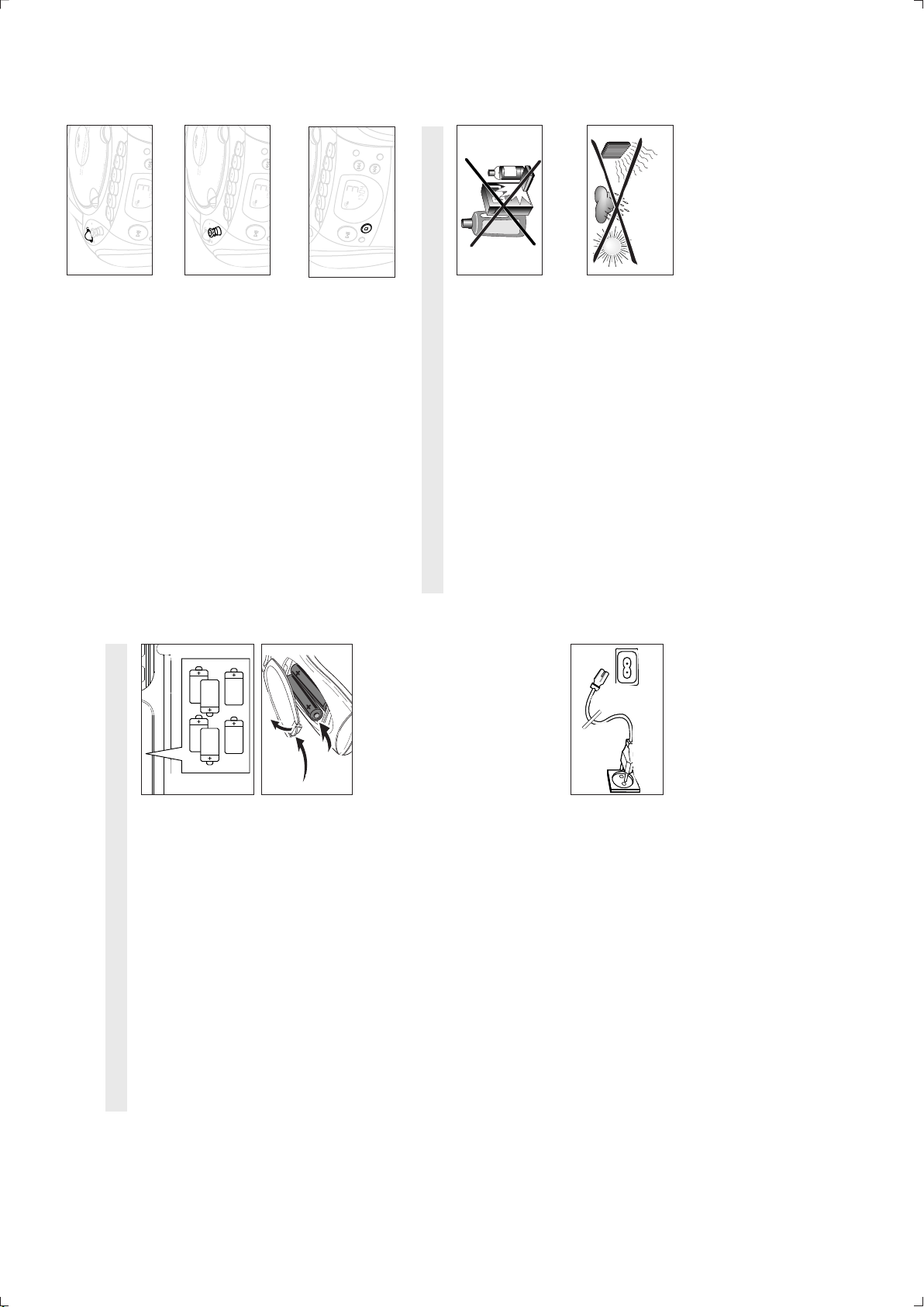
BATTERIES (OPTIONAL)
and wall socket before inserting batteries.
Whenever convenient, use the mains supply if you want to
1. Open the battery compartment and insert six batteries, type
compartment.
Remote control (supplied)
Open the battery compartment and insert two batteries,
type AAA, R03 or UM4 (preferably alkaline).
2. Replace the compartment door, making sure the batteries are
firmly and correctly in place. The set is now ready to operate.
– If BA
– The BATT LOW indicator eventually goes out if the
Incor
corrode the compartment or cause the batteries to burst.
Only use batteries of the same type for the set.
with the new ones.•Remove the batteries if the set is not to be used for a long
time.
Therefore:
• Do not mix battery types:e.g. alkaline with carbon zinc.
• When inserting new batteries, do not tr
be disposed of properly.
• Batteries contain chemical substances, so they should
Using AC MAINS
1. Check if the mains voltage as shown on the type plate on
the base of the set, corresponds to your local mains supply. If
it does not, consult your dealer or service centre.
selector so that it matches with the local mains supply.
ready for use.
3. Connect the mains lead to the wall socket and the set is now
remove the plug from the wall socket.
4. To disconnect the set from the mains supply completely
2. If your set is equipped with a voltage selector, adjust the
 Loading...