

Philips AZ-1137 Service Manual
CD Sound Machine
IT IS ONLY FOR Serial Number: NSxxxxxxxxx
AZ1137/55/77
TABLE OF CONTENTS
Page
Specifi cations ..........................................................................1
Software Version Checking ..................................................... 2
Set Block Diagram ................................................................3-1
Set Wiring Diagram ..............................................................3-2
Power Board ............................................................................4
VR Board .................................................................................5
LCD Board ...............................................................................6
Main & Aux Jack & Rect. Board...............................................7
Set Mechanical Exploded View & Parts List ............................8
©
Copyright 2009 Philips Consumer Electronics B.V. Eindhoven, The Netherlands
All rights reserved. No part of this publication may be reproduced, stored in a retrieval system or
transmitted, in any form or by any means, electronic, mechanical, photocopying, or otherwise without
the prior permission of Philips.
Published by SL 0945 Service Audio Printed in The Netherlands Subject to modifi cation
Version 1.1
CLASS 1
LASER PRODUCT
3141 785 34521

SPECIFICATIONS
Dimensions (W x H x D) 341 x 122 x 236 mm
Weight (main unit) 1.67 kg
Power supply DC 9V 1.5 A
Power consumption Active <12 W
Power output 2 x 1 W RMS
1 - 1
AC 110-127V, 60Hz
220-240V, 50Hz
Operating temperature
range
-10 °C - 50 °C
14 °F -122 °F

SOFTWARE VERSION CHECKING
Software checking:
2 - 1 2 - 1
Set at CD mode with no disc inserted --> then display shows "no" --> press and hold "Play" key for 5sec.
The software version will be showed on the display.
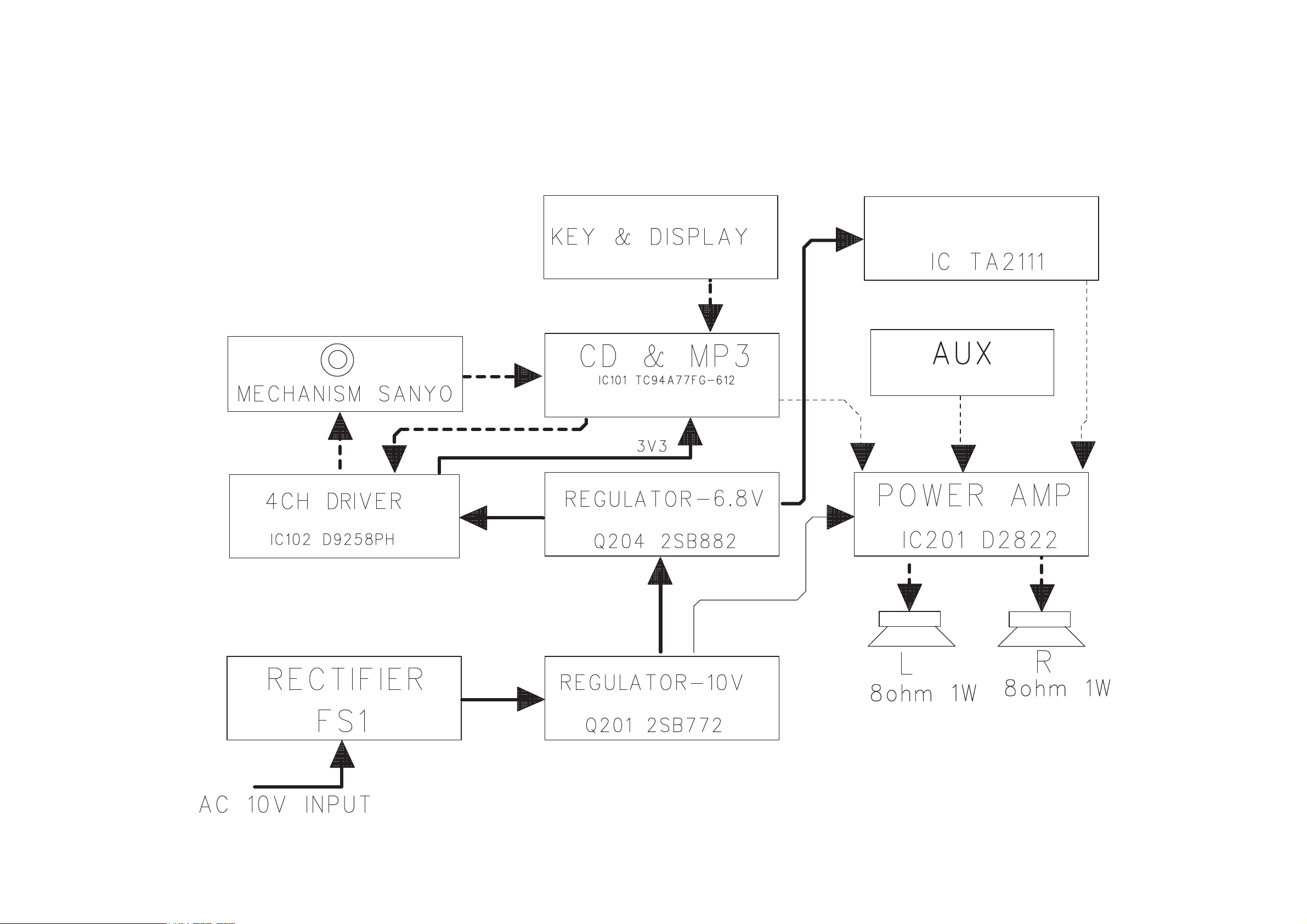
SET BLOCK DIAGRAM
3-1
3-1
TUNER
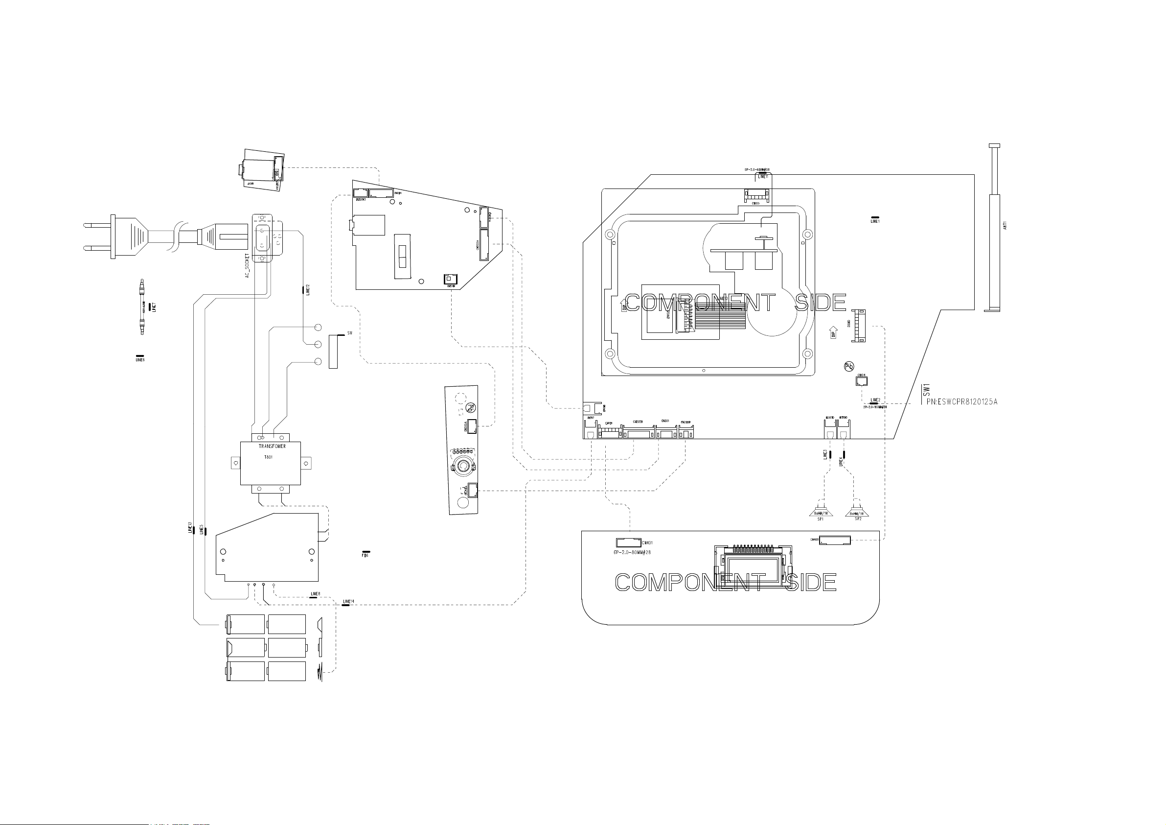
SET WIRING DIAGRAM
AUX BOARD
3 - 2
3 - 2
POWER BOARD
MAIN BOARD
RECT. BOARD
VR BOARD
LCD BOARD
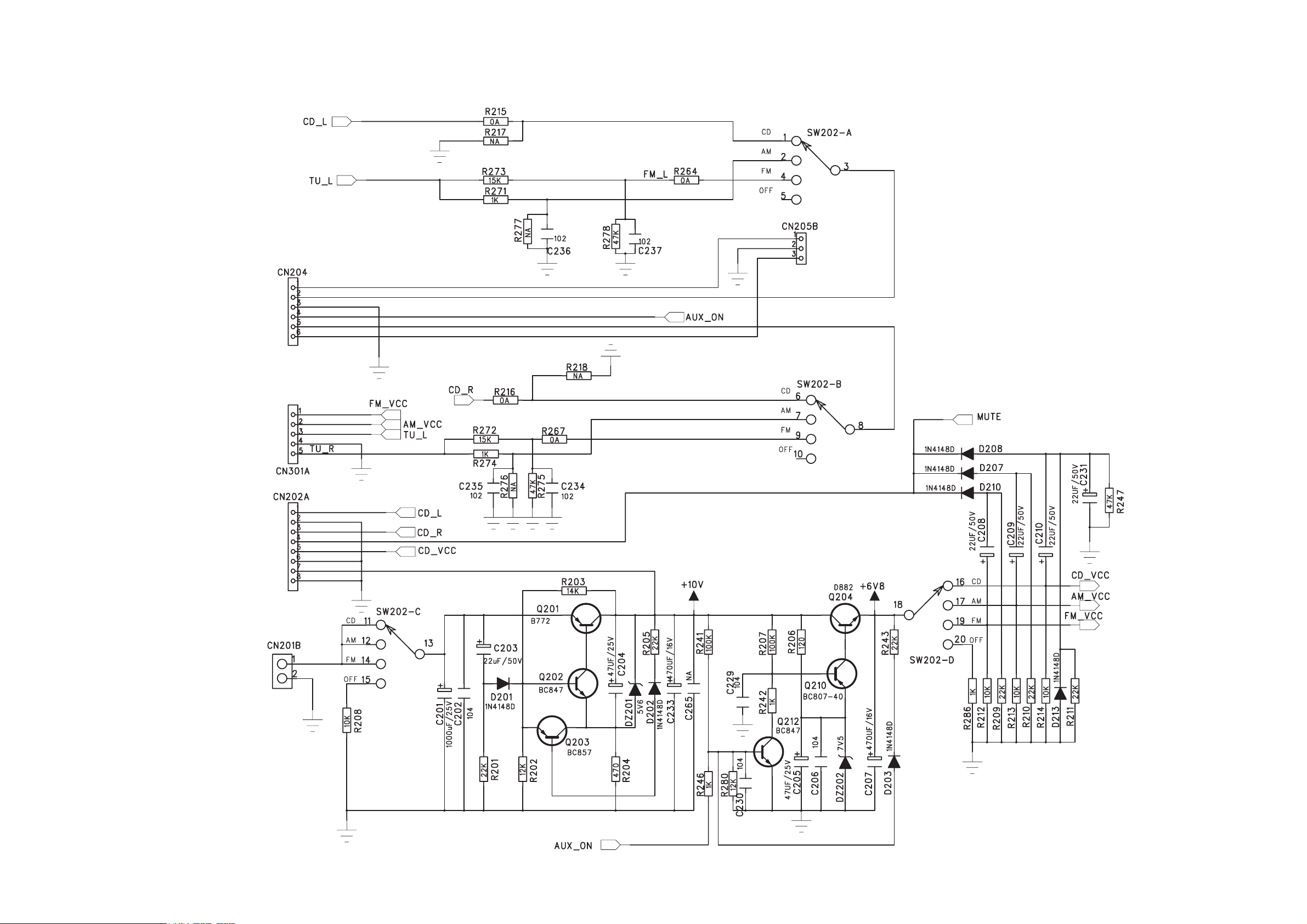
POWER BOARD - CIRCUIT DIAGRAM
4-14-1
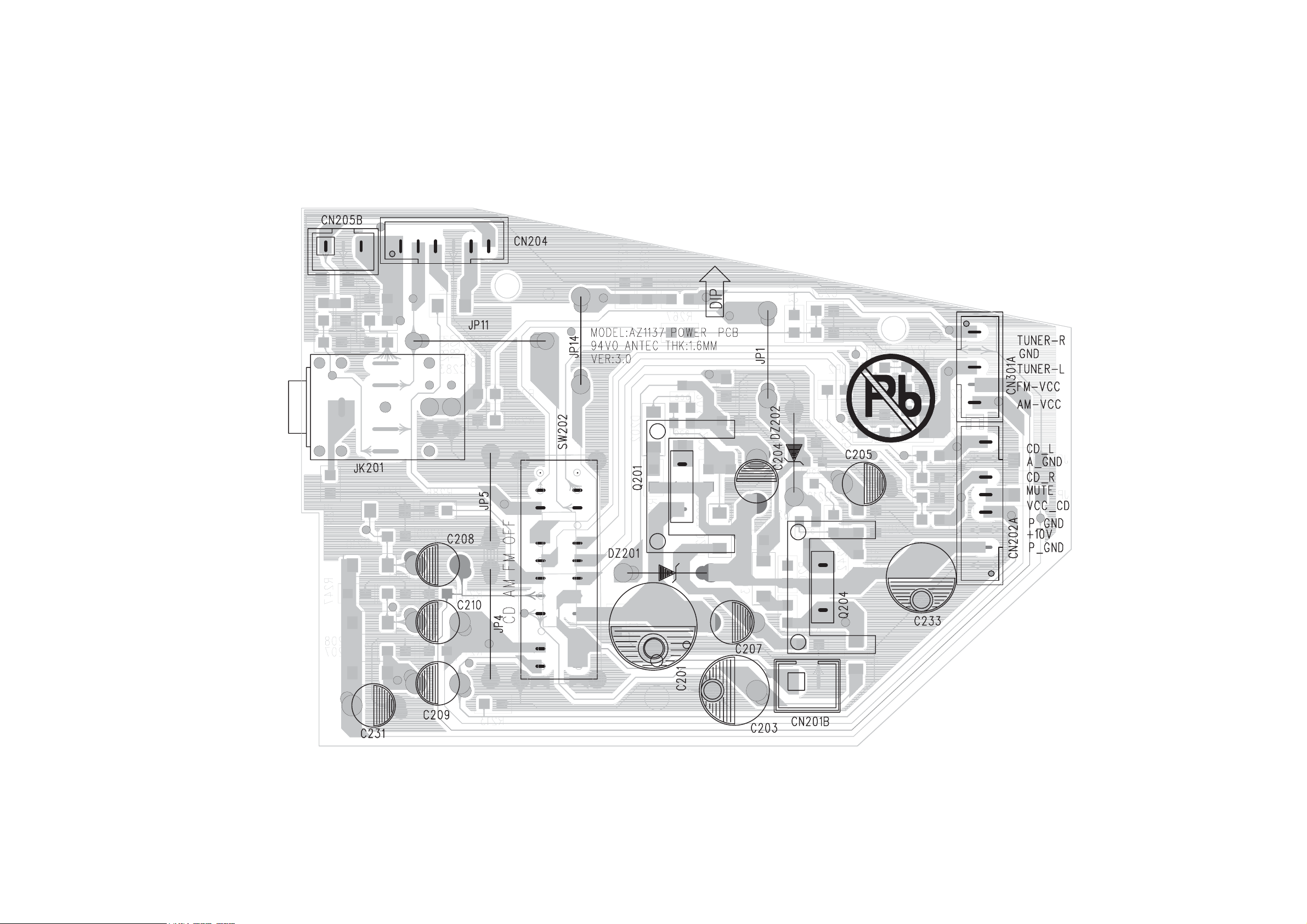
POWER BOARD - LAYOUT DIAGRAM
TOP VIEW
4 - 2
4 - 2
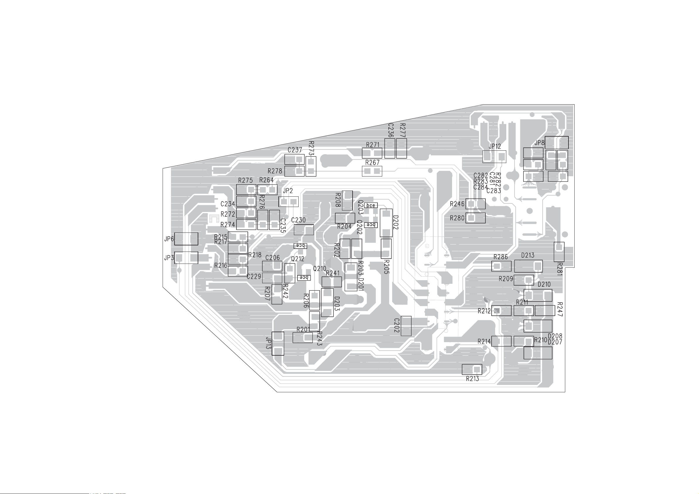
POWER BOARD - LAYOUT DIAGRAM
BOTTOM VIEW
4 - 3 4- 3
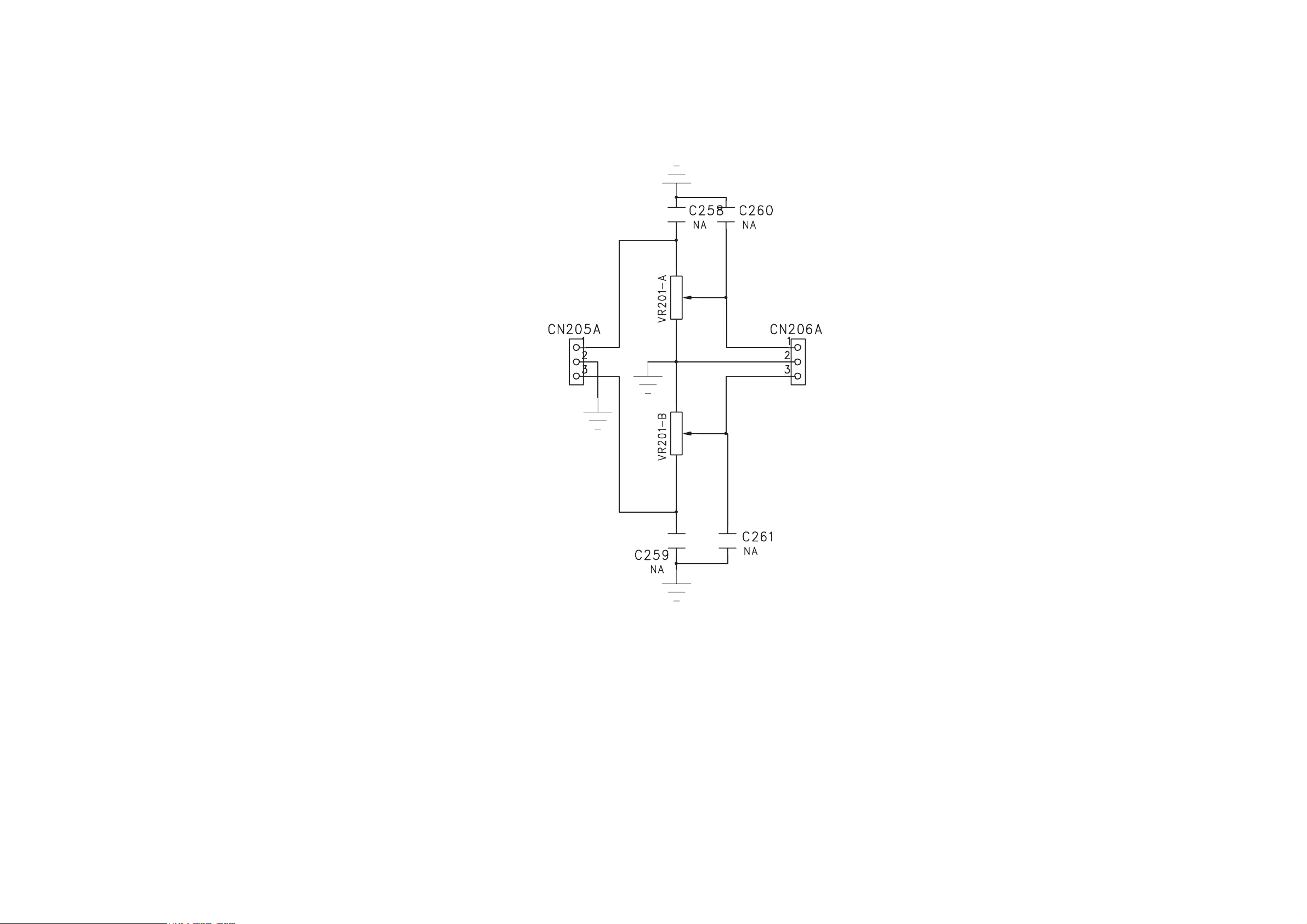
VR BOARD - CIRCUIT DIAGRAM
5 - 1 5 - 1
5 - 2 5 - 2
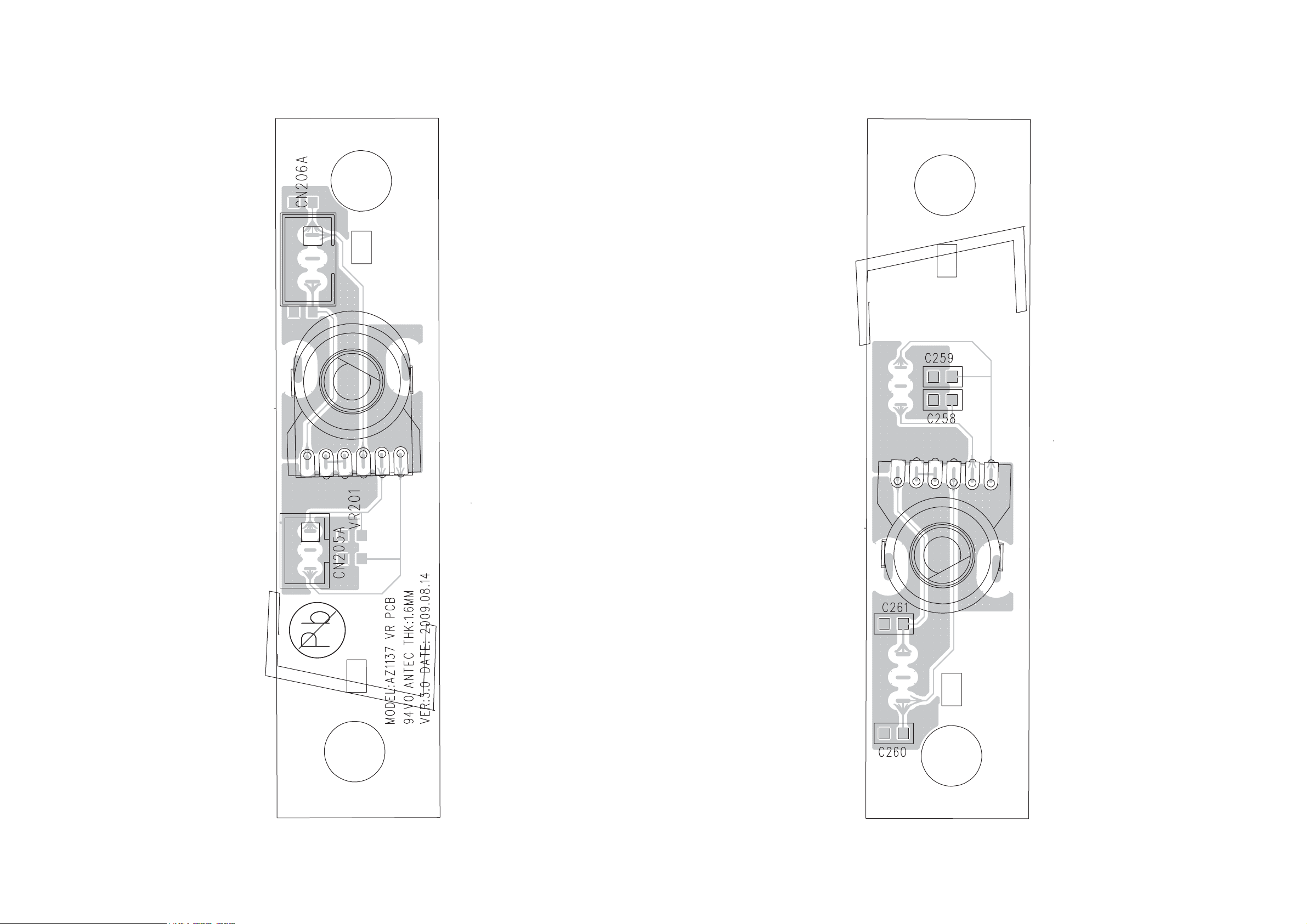
VR BOARD - LAYOUT DIAGRAM
TOP VIEW
VR BOARD - LAYOUT DIAGRAM
BOTTOM VIEW
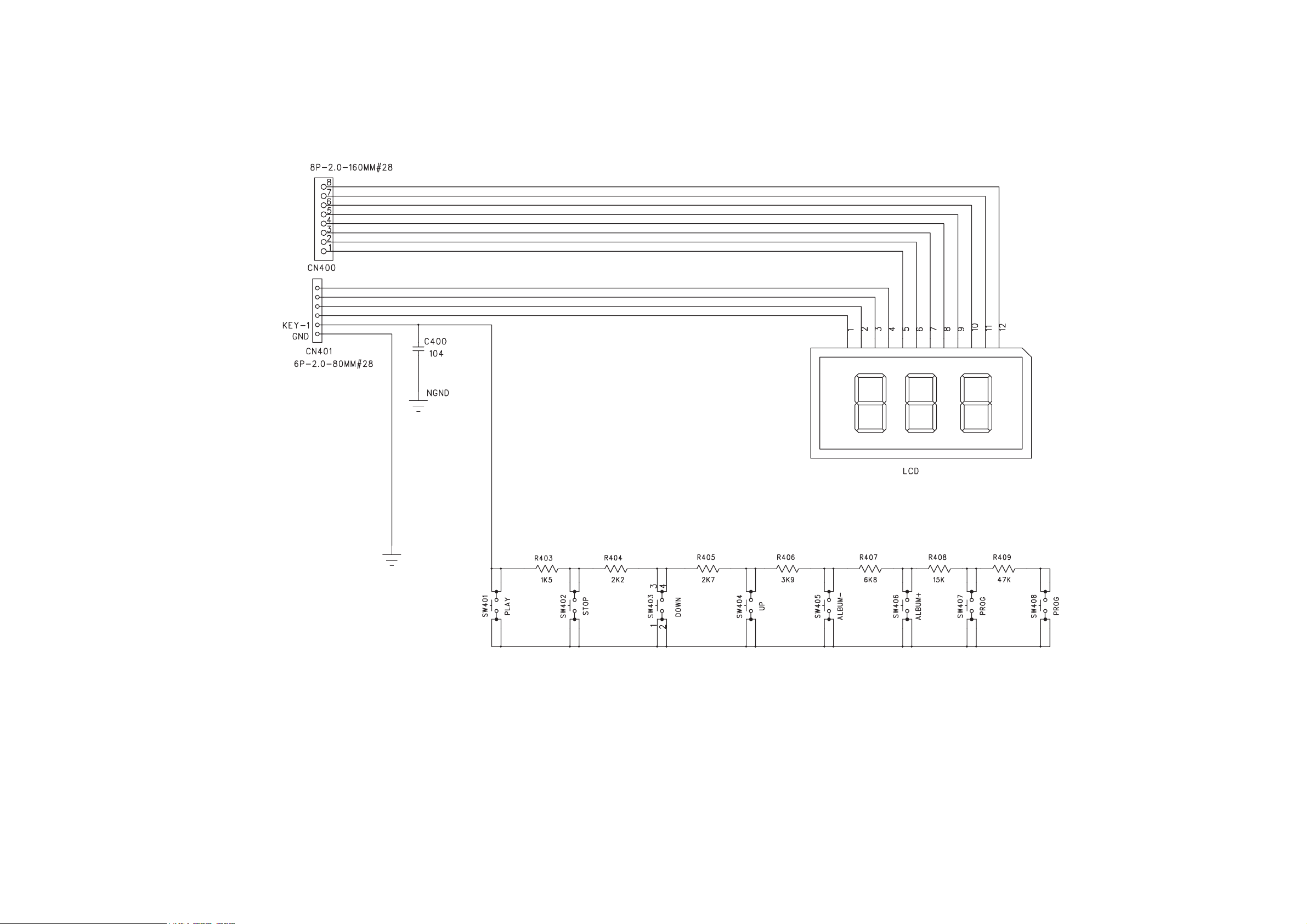
LCD BOARD - CIRCUIT DIAGRAM
6-1
6 - 1
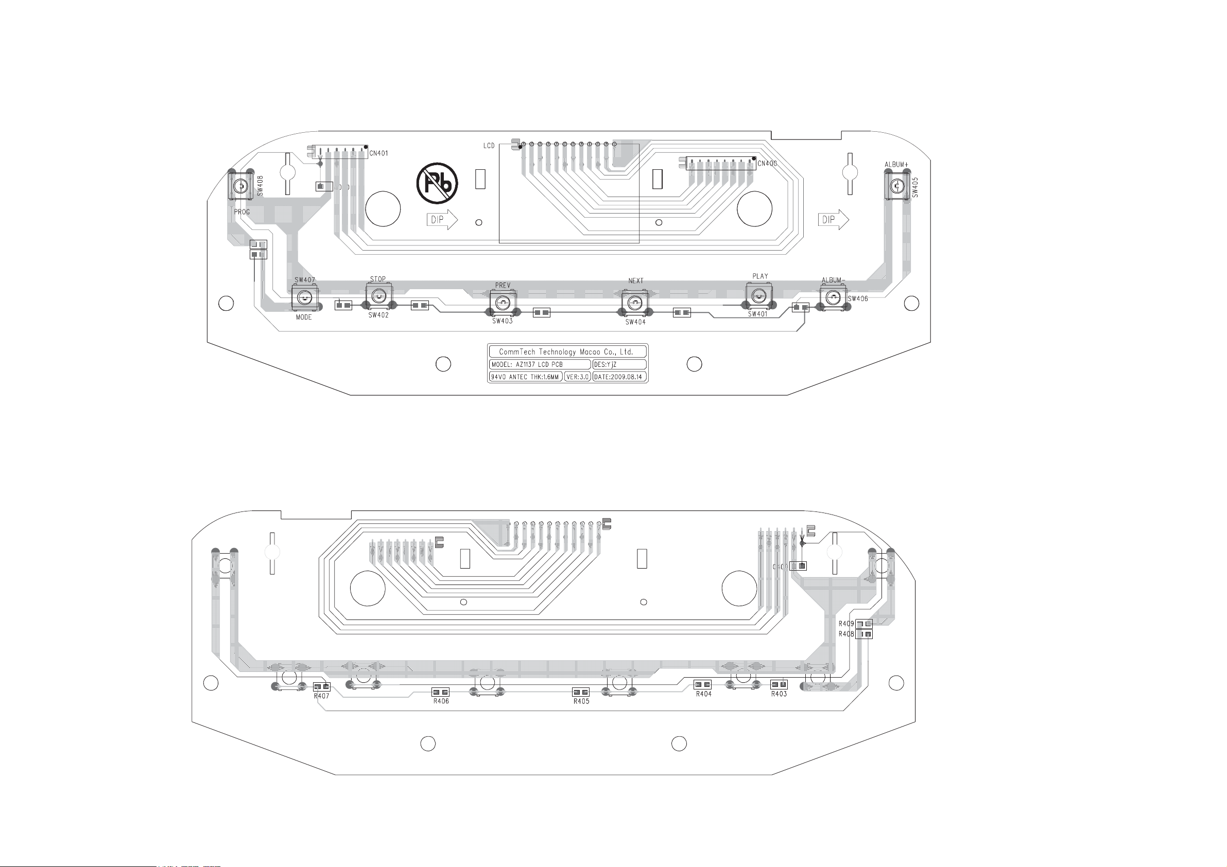
LCD BOARD - LAYOUT DIAGRAM
6 - 2 6 - 2
 Loading...