

Philips AZ-1080 Service manual
CD Soundmachine
AZ 1080
AZ 1081
all versions
© 3140 785 32020
Published by LX 0218 Service Audio Printed in The Netherlands Subject to modification
TABLE OF CONTENTS
©
Copyright 2001 Philips Consumer Electronics B.V. Eindhoven, The Netherlands
All rights reserved. No part of this publication may be reproduced, stored in a retrieval
system or transmitted, in any form or by any means, electronic, mechanical, photocopying,
or otherwise without the prior permission of Philips.
Handling Chip Components and Safety ..........................1 - 1
Technical Specification & Service tools...........................2 - 1
Service Measurement......................................................2 - 2
Connections and controls....................................3 - 1 to 3 - 2
Block Diagram .................................................................4 - 1
Wiring Diagram................................................................5 - 1
Front Board
Circuit diagram........................................................6 - 1
layout diagram.........................................................6 - 1
Tuner Board
circuit diagram.........................................................7 - 1
layout diagram.........................................................7 - 2
adjustment table......................................................7 - 2
Recorder Board
circuit diagram.........................................................8 - 1
layout diagram.........................................................8 - 2
adjustment...............................................................8 - 2
Combi Boad
circuit diagram.............................................9 - 1 to 9 - 2
layout diagram.............................................9 - 3 to 9 - 4
Exploded view diagram - cabinet...................................10 - 1
Exploded view diagram - tape deck ..............................10 - 2
Mechanical partslist.......................................................10 - 2
Electrical partslist ............................................11 - 1 to 11 - 6
CLASS 1
LASER PRODUCT
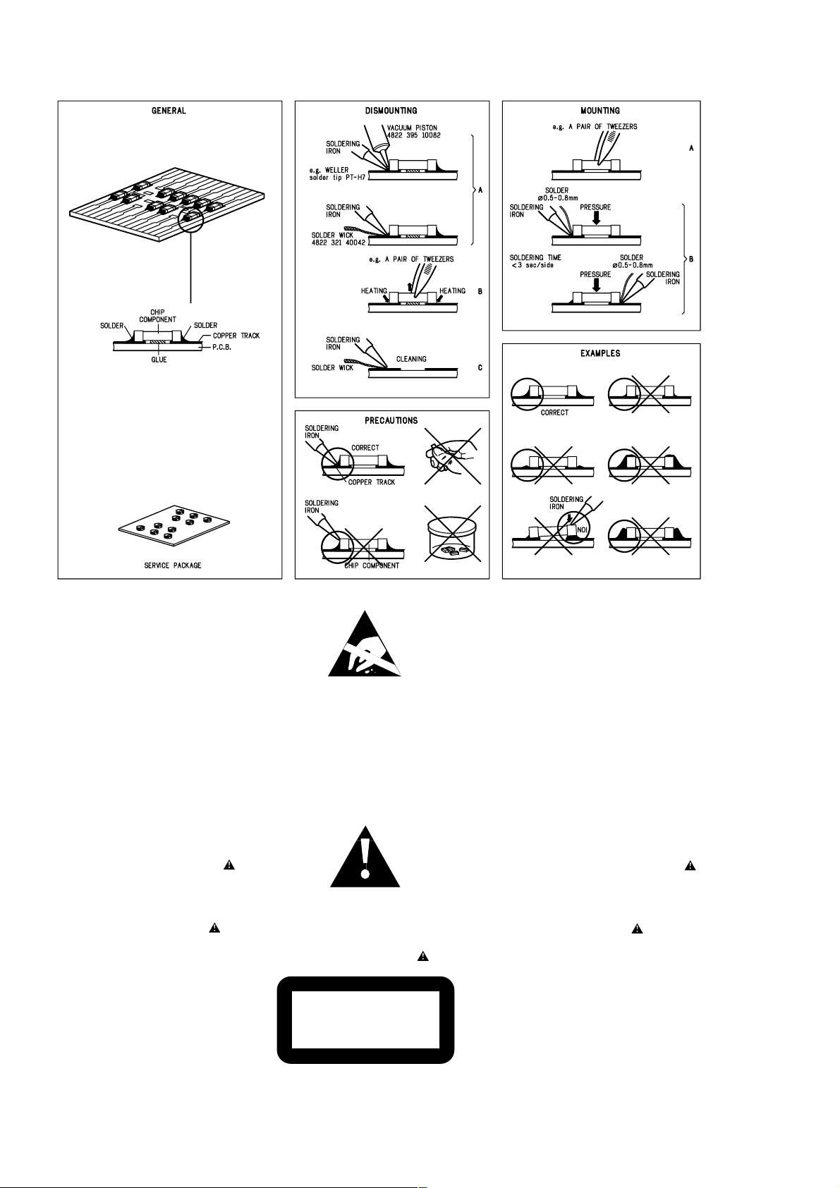
HANDLING CHIP COMPONENTS
1 - 1
© WARNING
All ICs and many other semiconductors are susceptible to
electrostatic discharges (ESD). Careless handling during
repair can reduce life drastically.
When repairing, make sure that you are connected with the
same potential as the mass of the set via a wristband with
resistance. Keep components and tools at this potential.
f ATTENTION
Tous les IC et beaucoup d´autres semi-conducteurs sont
sensibles aux décharges statiques (ESD). Leur longévite
pourrait être considérablement écourtée par le fait qu´aucune
précaution nést prise à leur manipulation.
Lors de réparations, s´assurer de bien être relié au même
potentiel que la masse de l´appareil et enfileer le bracelet
serti d´une résistance de sécurité.
Veiller à ce que les composants ainsi que les outils que l´on
utilise soient également à ce potentiel.
©
Safety regulations require that the set be restored to its
original condition and that parts which are identical with
those specified be used.
Safety components are marked by the symbol
f
Les normes de sécurité exigent que l`appareil soit remis
à l`état d`origine et que soient utilisées les pièces de
rechange identiques à celles spécifiées.
Les composants de sécurité sont marqués
d WARNUNG
Alle ICs und viele andere Halbleiter sind empfindlich
gegenüber elektrostatischen Entladungen (ESD).
Unsorgfältige Behandlung im Reparaturfall kann die
Lebensdauer drastisch reduzieren.
Sorgen Sie dafür, daß Sie im Reparaturfall über ein Pulsarmband mit Widerstand mit dem Massepotential des
Gerätes verbunden sind.
Halten Sie Bauteile und Hilfsmittel ebenfalls auf diesem
Potential.
d
Bei jeder Reparatur sind die geltenden Sicherheitsvorschriften zu beachten. Der Originalzustand des Gerätes
darf nicht verändert werden. Für Reparaturen sind Originalersatzteile zu verwenden.
Sicherheitsbauteile sind durch das Symbol markiert.
ESD
SAFETY
ñ WAARSCHUWING
Alle IC´s en vele andere halfgeleiders zijn gevoelig voor
electrostatische ontladingen (ESD).
Onzorgvuldig behandelen tijdens reparatie kan de levensduur
drastisch doen vermindern. Zorg ervoor dat u tijdens reparatie
via een polsband met weerstand verbonden bent met hetzelfde
potentiaal als de massa van het apparaat.
Houd componenten en hulpmiddelen ook op ditzelfde potentiaal.
i AVVERTIMENTO
Tutti IC e parecchi semi-conduttori sono sensibili alle scariche
statiche (ESD).
La loro longevità potrebbe essere fortemente ridatta in caso di
non osservazione della più grande cauzione alla loro
manipolazione. Durante le riparationi occorre quindi essere
collegato allo stesso potenziale che quello della massa
delápparecchio tramite un braccialetto a resistenza.
Assicurarsi che i componenti e anche gli utensili con quali si
lavora siano anche a questo potenziale.
ñ
Veiligheidsbepalingen vereisen, dat het apparaat in zijn
oorspronkeliijke toestand wordt teruggebracht en dat
onderdelen, identiek aan de gespecificeerde, worden toegepast.
De Veiligheidsonderdelen zijn aangeduid met het symbool
i
Le norme di sicurezza estigono che l´apparecchio venga
rimesso nelle condizioni originali e che siano utilizzati i
pezzi di ricambiago identici a quelli specificati.
Componenty di sicurezza sono marcati con
©
DANGER: Invisible laser radiation when open.
AVOID DIRECT EXPOSURE TO BEAM.
s Varning !
Osynlig laserstrålning när apparaten är öppnad och
spärren är urkopplad. Betrakta ej strålen.
∂ Advarsel !
Usynlig laserstråling ved åbning når sikkerhedsafbrydere
er ude af funktion. Undgå udsaettelse for stråling.
CLASS 1
LASER PRODUCT
ß Varoitus !
Avatussa laitteessa ja suojalukituksen ohitettaessa olet alttiina
näkymättömälle laserisäteilylle. Älä katso säteeseen !
©
After servicing and before returning the set to customer
perform a leakage current measurement test from all
exposed metal parts to earth ground, to assure no
shock hazard exists.
The leakage current must not exceed 0.5mA.
f
"Pour votre sécurite, ces documents doivent être utilisés par
des spécialistes agréés, seuls habilités à réparer votre
appareil en panne".

2 - 1
TECHNICAL SPECIFICATIONS
GENERAL
Mains voltage -/00/05/14 : 230 V
-/10 : 240 V
-/01
: 120 / 230 V
Mains frequency-/00/05/10/14 : 50 Hz
: 50 / 60 Hz
-/01
Battery : 9 V (R14 x 6)
Power consumption : 5 W
Dimension (W x H x D) : 400 x 235 x 173mm
Weight : 3 Kg
AMPLIFIER
Output power mains : 2 x 1 W
battery : 2 x 1 W
Speaker impedance : 2 x 8 ohm
Frequency response : 70 Hz - 3 kHz (±3dB)
TUNER - AM SECTION
Tuning range : 512 - 1635 kHz
IF frequency : 468 kHz ± 3 kHz
Sensitivity ::1500 µV/m at 26dB S/N
Selectivity 20 dB
IF rejection : 70 dB
Image rejection : 32 dB
CASSETTE RECORDER
Number of tracks : stereo
Tape speed : 4.76 cm/sec ± 3%
Wow & flutter : < 0.35% JIS WTD
Fast wind/rewind C60 : 130 sec.
Frequency response P/B : 125 - 8000 Hz
S/N ratio : 36 dB
COMPACT DISC
TUNER - FM SECTION
Tuning range : 87.35 - 108.25 MHz
IF frequency : 10.7 MHz ± 0.2 MHz
Sensitivity : 17 dB at 26dB S/N
Selectivity : 24 dB at 300kHz
IF rejection : 65 dB
Image rejection : 26 dB
S/N ratio : 55 dB
Channel difference 1 kHz : 2 dB
Channel crosstalk 1 kHz : 40 dB
THD 1 kHz : 0.2 %
SERVICE TOOLS
Audio signal disc SBC 429.......................................................................4822 397 30184
Playability test disc SBC 444
Test disc 5 (disc without errors ) +
Test disc 5A (disc with dropout errors, black spots and fingerprints)
SBC 426/426A.....................................................................4822 397 30096
Burn in test disc (65 min. 1kHz signal at -30 dB level without “pause”)
...................................................................4822 397 30245
.....4822 397 30155
AVAILABLE ESD PROTECTION EQUIPMENT
anti-static table mat
anti-static wristband
connection box (3 press stud connections, 1MΩ) 4822 320 11307
extendible cable (2m, 2MΩ, to connect wristband to connection box) 4822 320 11305
connecting cable (3m, 2MΩ, to connect table mat to connection box) 4822 320 11306
earth cable (1MΩ, to connect any product to mat or to connection box) 4822 320 11308
KIT ESD3 (combining all 6 prior products - small table mat) 4822 310 10671
wristband tester 4822 344 13999
large 1200x650x1.25mm 4822 466 10953
small 600x650x1.25m 4822 466 10958
4822 395 10223
2 - 2
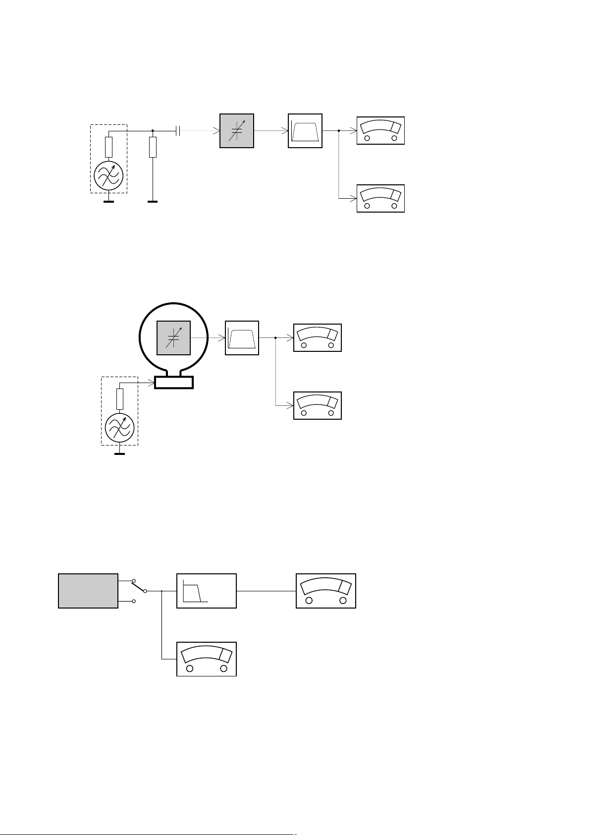
SERVICE MEASUREMENT
Tuner SW
RF Generator
e.g. PM5326
Aerial replacement
DUT
Capacitor
Ri=50Ω
R=50Ω
Bandpass
250Hz-15kHz
e.g. 7122 707 48001
LF Voltmeter
e.g. PM2534
S/N and distortion meter
e.g. Sound Technology ST1700B
To avoid atmospheric interference all AM-measurements have to be carried out in a Faraday«s cage.
Use a bandpass filter (or at least a high pass filter with 250Hz) to eliminate hum (50Hz, 100Hz).
Tuner AM (MW,LW)
RF Generator
e.g. PM5326
Ri=50Ω
DUT
Frame aerial
e.g. 7122 707 89001
Bandpass
250Hz-15kHz
e.g. 7122 707 48001
LF Voltmeter
e.g. PM2534
S/N and distortion meter
e.g. Sound Technology ST1700B
To avoid atmospheric interference all AM-measurements have to be carried out in a Faraday«s cage.
CD
Use Audio Signal Disc SBC429 4822 397 30184 (replaces test disc 3)
L.P.F. = 13
th
order filter 4822 395 30204
DUT
L
R
Low pass filter 22kHz
LEVEL METER
e.g. Sennheiser UPM550
with FF-filter
S/N and distortion meter
e.g. Sound Technology ST1700B
3 - 1
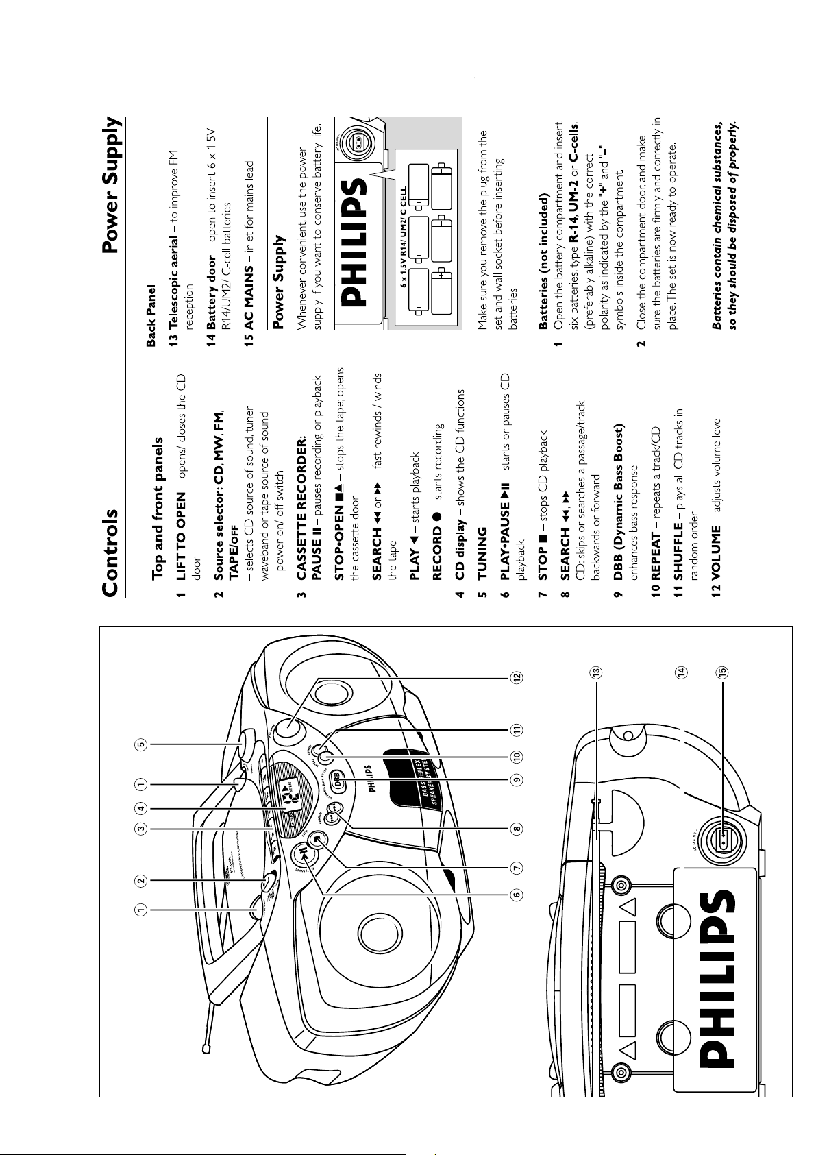
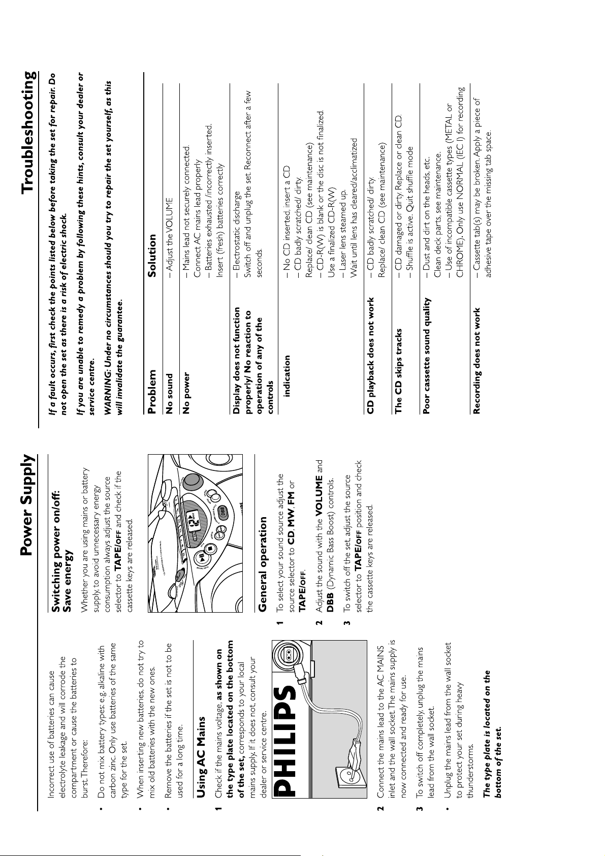
CONNECTIONS AND CONTROLS
3 - 2
4 - 14 - 1
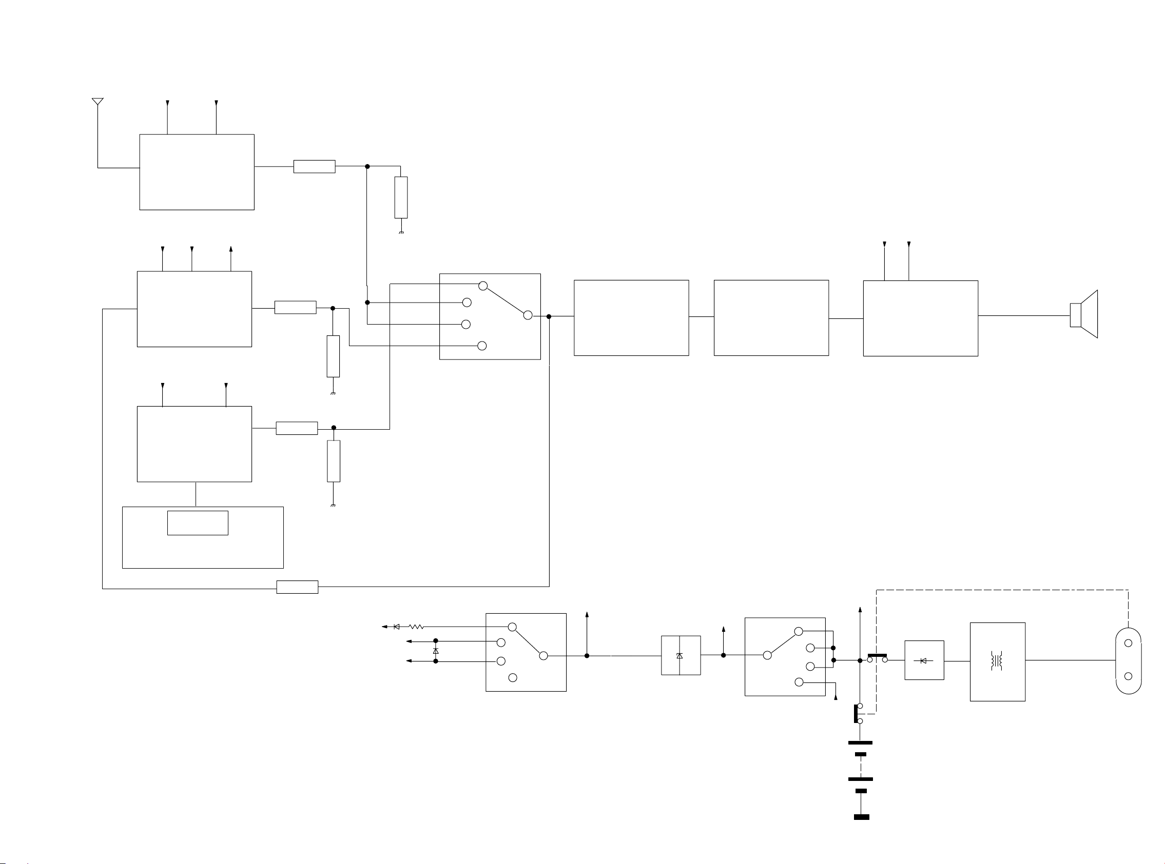
BLOCK DIAGRAM
FM+TUNER
ATM5
2 BAND TUNER
+B
+A
ECO-MTF-SD
TAPE MODULE
+CD
CD MX
+1
+A_ON
R
R
+A_ON
+A
CD
MW
R
FM
DBB
RO TAR Y V OLUME
TAPE
R
R
POWER AMP
TA8227P
8 OHM
LOUDSPEAKER
LCD
Control panel
R
R
+CD
+TUNER
+FM
1N4003
CD
1R
1N4148
MW
FM
+B
+A_ON
BZX55-B4V7
TAPE
CD
MW
FM
TAPE
+1
+A
RECTIFIER
1N4003
TRANSFORMER
97TS-031A
1.5 V X 6
5 - 1 5 - 1
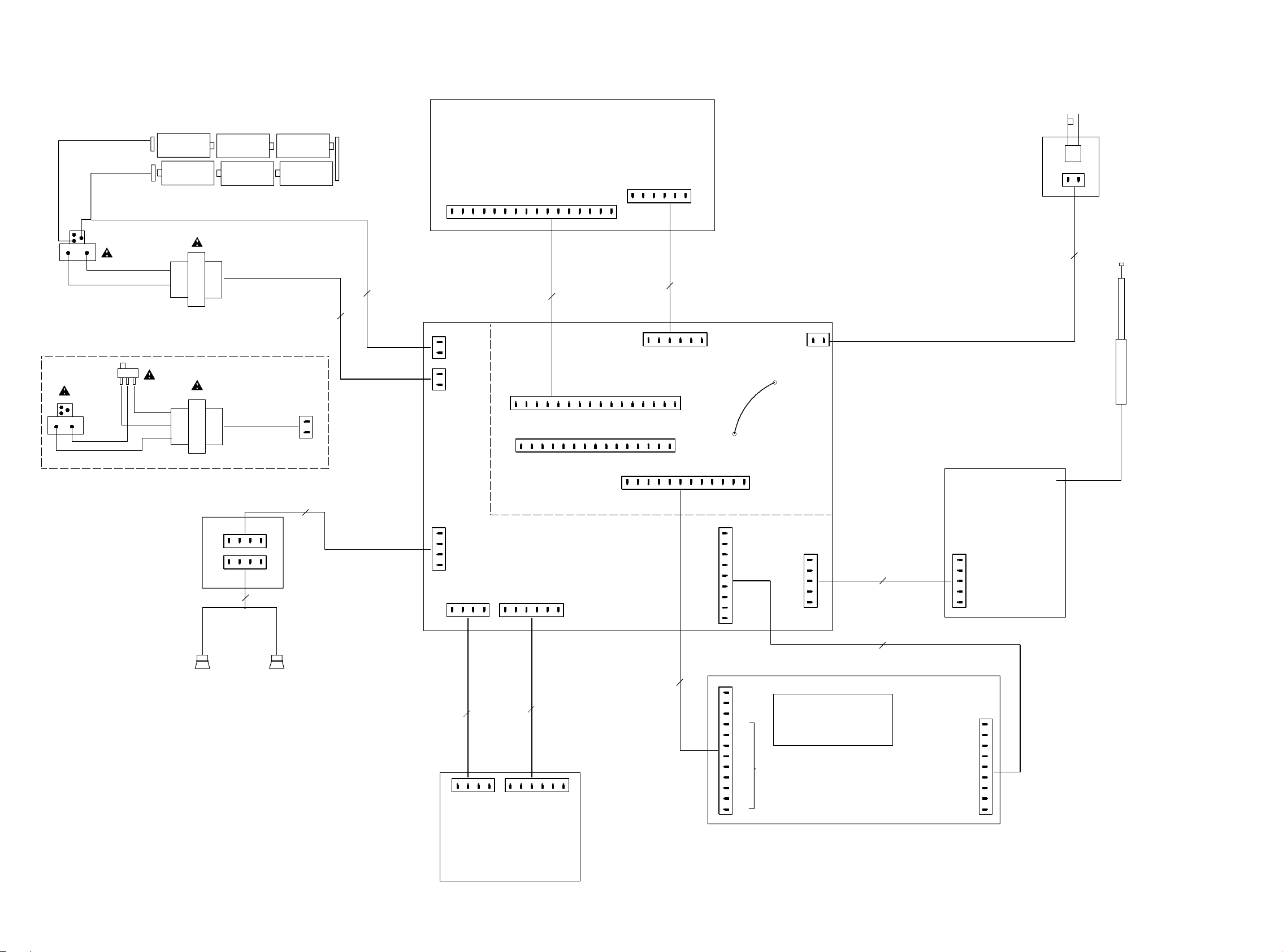
WIRING DIAGRAM
8254
BATTERY COMPARTMENT
FOR /01/11 ONLY
8255
VOLTAGE SELECTOR
CD DOOR SW
1
2
1
2345678
CD DRIVE MITSUMI MCD1B
PH-B
12345
9
101112
13
141516
DIPMATE
1805
6
2P
8801
2P
8803
16P
6P
8802
8253
2P
1
2
3
GND
E
D
D5
VCC
34
234
456
/ INNERSW
Vcc
D3
2
1
SLEDGE-
Vc
110111213141516 2345678
GND
678
5
DISC-
SLEDGE+
1801
FMZ-ST
DISC+
8000
(For MITSUMI MCD1B only)
0100
9
101112
0200
1256
PH-B
1
+BATT
2
GND
1
AC
2
AC
EH-B
1255
1255
EH-B
1
2
1801
FMZ-ST
FOC-
FOC+
TR+
TR-
FOC-
FOC+
TR-
LD
GND
LD-PD
9
TR+
GND
D1
D2
1112131415
10
CD LAYOUT CELL
1802
PH-B
CFGND
A
B
VC
LD
MON
D4
56
789
1803
FE-BT-VK-N
1
2
DOOR_SW
1804
EH-B
1
TUNER MODULE
8101
100MM
1260
DIPMATE
123
4
1261
EH-B
123
4
4P
8252
LEFT
RIGHT
LOUDSPEAKERS
4P
8251
DIPMATE
1259
1
2
3
4
1253
DIPMATE
R
GND
GND
L
+A
123
1258
FE-BT-VK-N
AF BOARD
GND_MOTOR
4
3
1702
+1
4P
8702
2
REC_INFO
4
1
EH-S
L_IN
R_IN
123
GND
456
L_OUT
456
6P
8701
AD
1725
+TAPE
R_OUT
2
3
FE-ST-VK-N
1252
FE-BT-VK-N
1
12P
8401
BD
1
2
3
4
5
6
7
8
9
FE-ST-VK-N
1406
1
GND
2
KEY_1
3
KEY_2
4
PIN_1
PIN_2
5
PIN_3
6
PIN_4
7
PIN_5
8
9
10
11
12
LCD
PIN_6
PIN_7
PIN_8
PIN_9
FE-ST-VK-N
1254
1
2
3
4
5
5P
9P
LCD
FRONTBOARD
8102
AD
8501
AD
ATM5 2BAND
FE-BT-VK-N
1110
L
1
2
GND
3
R
+B
4
5
+FM
1251
FE-ST-VK-N
+A_ON
AC_ON
L_OUT
R_OUT
GND
L_IN
GND
GND
R_IN
1
2
3
4
5
6
7
8
9
ECO-MTF-PA-SD
TAPE MODULE
 Loading...