

Philips AX-5118 Service Manual
PRODUCT FAMILY FOCUS ESP
Technical specification ......................................................1-1
Connections and controls..................................................1-2
Features ............................................................................1-3
Accessories.......................................................................1-3
Safety & Warnings.............................................................1-4
Service hints
Repair positions ............................................................2-1
Dismantling CD-door.....................................................2-1
Handling chip components............................................2-2
Service tools..................................................................2-2
Pin description of ICs ................................................3-1...3-3
Start-up procedure.............................................................3-4
Service Test Program................................................3-5...3-6
Blockdiagram.....................................................................3-7
Circuit diagrams
CD part..........................................................................4-1
Control / Supply partpart...............................................4-2
Audio part......................................................................4-3
PCB layout diagram
Componentside view.....................................................4-4
Copperside view............................................................4-5
Exploded view ...................................................................5-1
Mechanical partslist...........................................................5-1
Electrical partslist ......................................................6-1...6-4
© 3140 785 22870
Published by YT 0150 Service Audio Printed in The Netherlands Subject to modification
Portable compact disc player
AX 2100
AX 2101
AX 2102
AX 5100
AX 5101
AX 5102
AX 5103
AX 5104
AX 5111
AX 5112
AX 5113
AX 5114
AX 5115
AX 5116
AX 5117
AX 5118
AX 7101
AX 7104
AX 7113
all versions
TABLE OF CONTENTS
©
Copyright 2001 Philips Consumer Electronics B.V. Eindhoven, The Netherlands
All rights reserved. No part of this publication may be reproduced, stored in a retrieval
system or transmitted, in any form or by any means, electronic, mechanical, photocopying,
or otherwise without the prior permission of Philips.
CLASS 1
LASER PRODUCT
1-1
General
Dimensions (WxHxD) : 129x26x140mm
Weight without batteries : 220g
Power supply modes
DC-in socket : 2.5-6.0V
Primary batteries (2xLR6) : 1.7-3.6V
Rechargable batteries (AY3362) : 1.7-3.6V
Battery lifetime
Battery level detection
Charge section (not on all versions)
Charge current : 250mA ±10%
Charge time for 80% AY3362 : 4.0h nom.
Charge time for 100% AY3362 : 6.0h nom.
Max. charge time (µP controlled) : 7h
Temperature protection : 50°C ±5°C
Current consumption CDDA-playback
Shock resistance
+X/-X direction : ≥2.5g
+Y/-Y direction : ≥2.5g
+Z/-Z direction : ≥2.0g
Headphone out (measured with 16Ω load, DBB/ESP off)
Output power (THD=10%)
/17 version only : 2x12mW (+1/-3dB)
all other versions : 2x6mW (+1/-3dB)
Frequency response (1mW) : 100Hz-20kHz within 6dB
S/N ratio (unwght) : ≥80dB (83dB typ.)
S/N ratio (A-wght) : ≥82dB (85dB typ.)
THD+N (1kHz, 1mW) : ≤1% (0.2% typ.)
Channel crosstalk (1kHz, no load): ≤-24dB (-44dB typ.)
Channel unbalance (-40dB) : ≤5dB
Volume attenuation (1kHz) : ≥60dB
Dynamic Bass Boost DBB
Laser
Output power : <5mW (3mW typ.)
Wavelength : 780nm
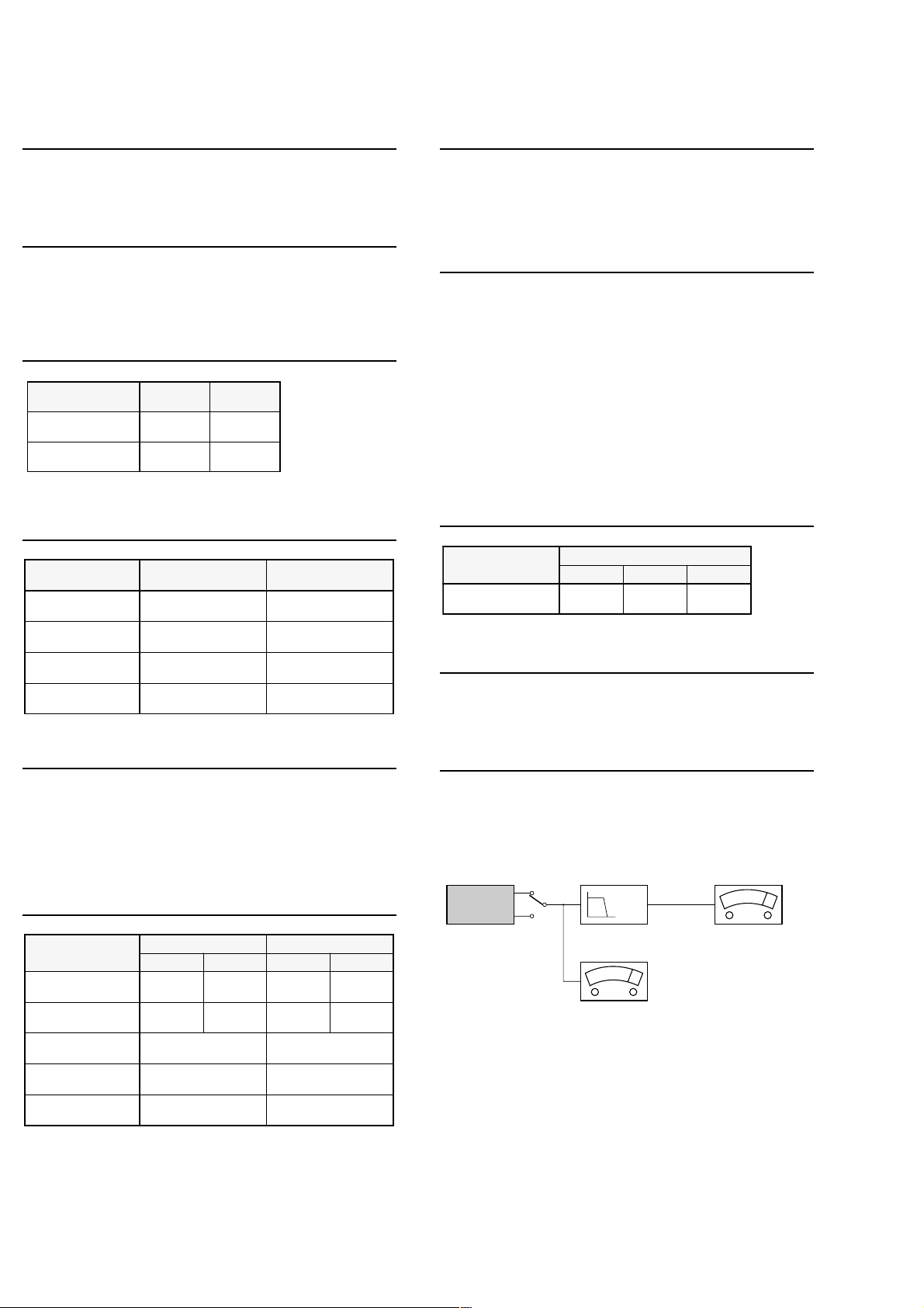
Measurement setup
Use Audio Signal disc SBC429 4822 397 30184
TECHNICAL SPECIFICATION
Power Save
EPYTYRETTAB
seirettabyramirP
6RLx2
seirettabelbagrahceR
)hAm0021(2633YA
OPSE N
ON
25 hours22 hours
10 hours9 hours
LEVELNOITCETED seirettabyramirP seirettabelbagrahceR
ytpmeyrettaB
1kaewyrettaB
2kaewyrettaB
3kaewyrettaB
V8.1
Vm05-/001+
V9.0
±
V6.0
±
V3.0
±
+levelytpmeyrettab
Vm001
+levelytpmeyrettab
Vm001
+levelytpmeyrettab
Vm001
V7.0
±
V5.0
±
V3.0
±
EGATSBBD
V8.1
Vm05-/001+
+levelytpmeyrettab
Vm001
+levelytpmeyrettab
Vm001
+levelytpmeyrettab
Vm001
1BBD Bd8+ ± Bd2 Bd0 ± Bd2 Bd0 ± Bd2
zHk36 zHk1 zHk01
esnopserycneuqerF
EDOMNOITAREPO
edom-yalP.pytAm001.pytAm001.pytAm021.pytAm021
edom-pmuJ.pytAm022.pytAm022.pytAm003.pytAm003
edom-egrahC.pytAm004a/n
gnithgilkcaB
)lanoitidda(
yb-dnatS
)egrahcer.lcxe(
FFOPSE NOPSE FFOPSE NOPSE
)V5.4(YLPPUSNI-CD )V52.2(YLPPUS.TTAB
.pytAm05.pytAm05
.pytAm0305
Use Audio Signal Disc SBC429 4822 397 30184 (replaces test disc 3)
L.P.F. = 13
µ
.pytA
th
order filter 4822 395 30204
DUT
L
R
Low pass filter 22kHz
LEVEL METER
e.g. Sennheiser UPM550
with FF-filter
S/N and distortion meter
e.g. Sound Technology ST1700B
1-2
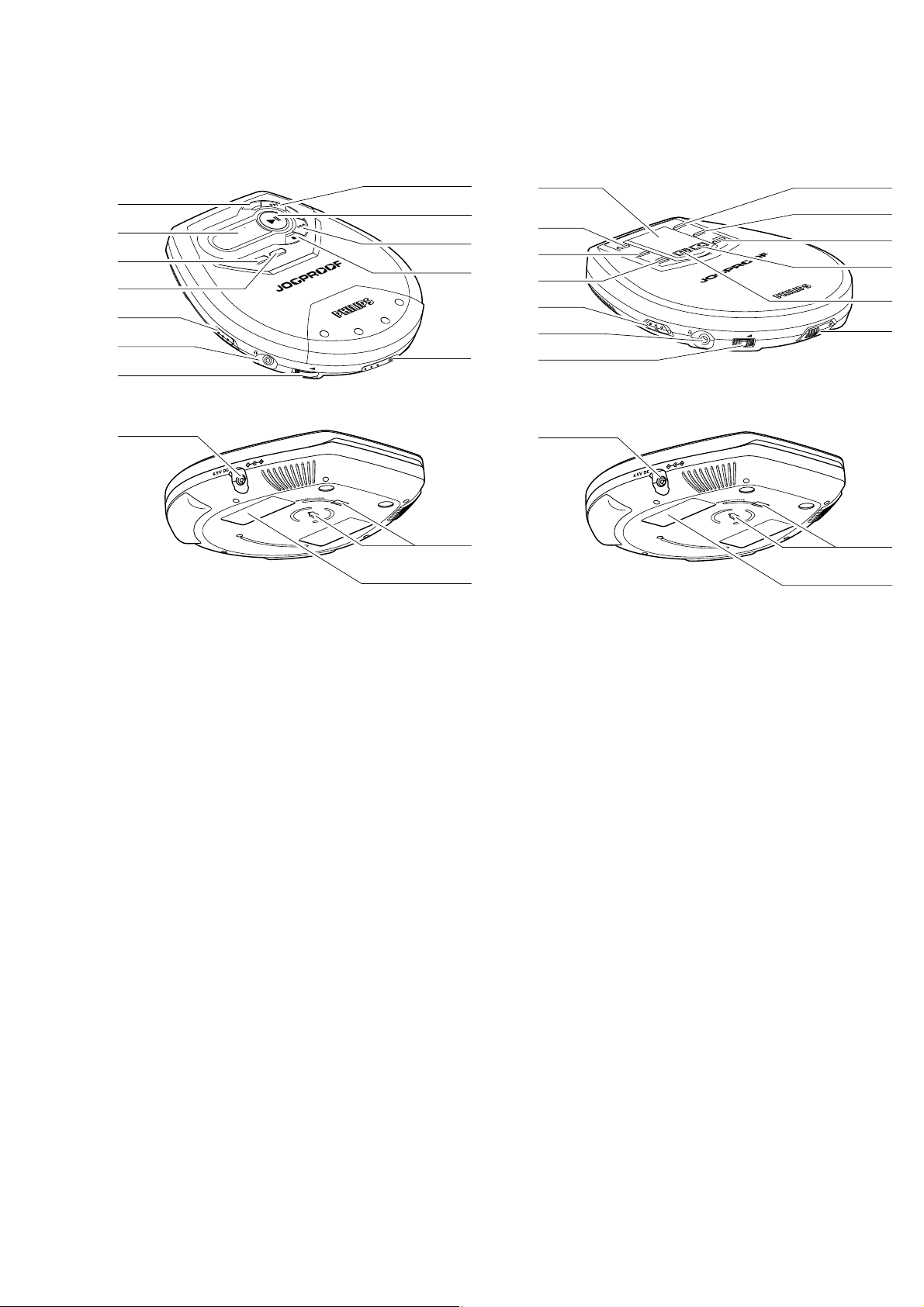
CONNECTIONS AND CONTROLS
AX21.. & AX51..
1 OPEN 2..............opens the CD lid
2 9 ......................stops CD play, clears a program or switches the
player off
3 ∞ .....................skips and searches CD tracks backwards
4 2; ....................switches the player on, starts or pauses CD play
5 § .....................skips and searches CD tracks forwards
6 DBB.................switches the bass enhancement on and off. This
button also switches acoustic feedback (the
beep) on/off when it is pressed for more than 2
seconds
7 ........................display
8 PROGRAM......programs tracks and reviews the program
9 MODE..............selects the different playing possibilities:
SHUFFLE,
SHUFFLE REPEAT ALL, REPEAT, REPEAT ALL and
SCAN
0 RESUME.........stores the last position of a CD track played
HOLD ..............locks all buttons
OFF.................switches RESUME and HOLD off
! LINE OUT/p ....3.5 mm headphone socket, socket to connect the
player to another audio input of an additional
appliance, remote control socket (not on all
versions)
@ VOL E ..........adjusts the volume
# 4.5V DC...........socket for external power supply
$ ........................belt clip holder
% ........................typeplate
AX71..
1 OPEN 2..............opens the CD lid
2 2; ....................switches the player on, starts or pauses CD play
3 9 ......................stops CD play, clears a program or switches the
player off
4 § .....................skips and searches CD tracks forwards
5 ESP .................ELECTRONIC SKIP PROTECTION ensures
continues CD playback regardless of vibrations
and shocks
6 MODE..............selects the different playing possibilities:
SHUFFLE,
SHUFFLE REPEAT ALL, REPEAT, REPEAT ALL and
SCAN
7 ........................display
8 PROGRAM......programs tracks and reviews the program
9 BASS...............switches the bass enhancement on and off. This
button also switches acoustic feedback (the
beep) on/off when it is pressed for more than 2
seconds
0 ∞ .....................skips and searches CD tracks backwards
! RESUME.........stores the last position of a CD track played
HOLD ..............locks all buttons
OFF.................switches RESUME and HOLD off
@ LINE OUT/p ....3.5 mm headphone socket, socket to connect the
player to another audio input of an additional
appliance, remote control socket (not on all
versions)
# VOL E ..........adjusts the volume
$ 4.5V DC...........socket for external power supply
% ........................belt clip holder
^ ........................typeplate
For more information of operation instruction
please visit Philips Audio internet site :
http://www.audio.philips.com
6
7
8
9
0
!
@
#
O
F
F
•
R
E
S
U
M
E
•
H
O
L
D
5
B
B
D
K
C
A
R
T
E
D
O
M
E
OD
M
ST
IGITA
D
IC BA
AM
L DYN
O
SS BO
CD REWRITABLE COMPATIBLE
V
O
L
.
0
N
E
P
O
AM
GR
PRO
L
I
N
E
O
U
T/
4
3
2
1
8
9
0
!
@
#
E
D
O
M
P
S
E
T
S
O
O
B
S
E
L
S
B
A
I
B
T
A
P
C
I
M
M
O
A
C
N
M
A
R
G
O
R
P
O
F
F
•
R
E
S
U
M
E
Y
E
D
L
B
L
A
T
A
I
T
R
I
G
W
I
E
D
R
D
C
S
S
A
B
•
H
O
L
D
L
I
N
E
O
U
T
/
V
.
O
L
N
E
P
O
$
$
%
67
5
4
3
2
1
%
^

1-3
FEATURES
FEATURES OF CD-PORTABLE
PRODUCT FAMILY FOCUS ESP
CD-RW COMPA TIBILITY
ELECTRONIC SKIP PROTECTION
ESP DRAM SIZE [Mbit]
HOLD / RESUME FUNCTION
DBB STAGES
ACOUSTIC FEEDBACK
PROGRAM MEMORY
RECHARGE NiCd / NiMH
BELT-CLIP
CORD REMOTE CONTROL
LINE / OPT. DIGITAL OUTPUT
ACCESSORIES
AX2100
●
12s
16
●/●
1
●
30
--/--
●
--
--/--
AX2101
●
12s
16
●/●
1
●
30
--/--
●
--
--/--
AX2102
●
12s
16
●/●
1
●
30
●/●
●
--
--/--
AX5100
●
45s
45s
16
●/●
●/●
1
●
30
--/-- --/--
--/--
●
--
--/--
--/--
AX5101
●
45s
16
16
●/●
1
●
30
●/●
●
--
--/--
AX5102
●
45s
●/●
1
●
30
●
--
--/--
AX5103
●
45s
16
16
●/●
1
●
30
30
●/●
●
--
--/--
AX5104
●
●
45s
16
●/●
1
●
●
30
--/--
●
●
●
--/--
AX5111
●
45s
16
●/●
1
1
●
30
●/●
●
--
--
--/--
AX5112
AX5113
●
45s
16
●/●
1
●
30
--/--
●
--
--/--
AX5114
●
45s
16
●/●
1
●
30
--/--
●
●
--/--
AX5115
●
45s
16
●/●
1
●
30
--/--
●
--
--/--
AX5116
●
45s
16
●/●
1
●
30
--/--
●
--
--/--
AX5117
●
45s
16
●/●
1
●
30
--/--
●
--
--/--
AX5118
●
●
100s
45s
32
16
●/●
●/●
1
●
●
30
30
--/--
--/--
●
●
●●
--/--
--/--
AX7101
●
100s
32
●/●
1
1
●
30
●/●
●
●●
--/--
AX7104
AX7113
●
100s
32
●/●
1
●
30
--/--
●
--/--
ACCESSORIES FOR CD-PORTABLE
PRODUCT FAMILY FOCUS ESP
AY3170/00 AC/DC Adaptor
AY3170/02 AC/DC Adaptor
AY3170/05 AC/DC Adaptor
AY3170/10 AC/DC Adaptor
AY3170/12 AC/DC Adaptor
AY3170/17 AC/DC Adaptor
AY3266/00 Pouch
AY3362/00 Rechargable Batt. NiMH
AY3464 HiFi Cord
AY3501/00 Car Adaptor Cassette
AY3545/00 Car DC/DC Converter
AY3545/17 Car DC/DC Converter
AY3768/00 Cord Remote Control
HE205/77 Headphone
HE205/77s Headphone
HL351/77 Headphone
HL351/77s Headphone
BELT-CLIP
X...supplied with the set, O...optional available
(Neoprene)
(3.5mm L-plug→cinch)
(S-plug)
(S-plug)
4822 219 10617
4822 219 10676
4822 219 10672
4822 219 10681
4822 219 10671
4822 219 10616
3140 113 10360
3103 308 84120
4822 320 11881
4822 397 10059
4822 219 10033
3140 118 32970
3140 118 50980
9082 100 00615
9082 100 00616
9082 100 00639
9082 100 00641
3103 304 70250
AX2100
AX2101
AX2002
/00
/00c
/00c
O
X
X
OOOO OOOOOOO
OOOO OOOOOOO
OOOO OOOO O
OOOO OOOO O
X
XOXXX
AX5100
AX5101
/05
/00
/00c
X
XX
XXX
XXX
X
AX5103
AX5102
/11
/00
/01
X
X
X
X
X
X
XXXXXXX
/10
XX
X
X
X
X
XX
XXX
AX5104
/05
/00c
O
X
O
OOOOOO
OO
X
XXXXX
AX5113
AX5112
AX5111
/17
/17
OO OOOOOO O
OO OOOOOO O
OOOOOOOOO
OO OO
AX5114
AX5116
AX5115
/00
/17
/17
/17
/17
X
O
XXXX X
XXXX X
X
X
X
X
X
XXXXXXXXXXXXX
X
AX5118
AX5117
/17
/17
X
AX7101
AX7104
/17
/00
X
O
O
X
OOOO
OO
O
O
X
XXX
X
AX7113
/17
1-4
SAFETY & WARNINGS
© WARNING
All ICs and many other semiconductors are susceptible to
electrostatic discharges (ESD). Careless handling during
repair can reduce life drastically.
When repairing, make sure that you are connected with the
same potential as the mass of the set via a wristband with
resistance. Keep components and tools at this potential.
f ATTENTION
Tous les IC et beaucoup d´autres semi-conducteurs sont
sensibles aux décharges statiques (ESD). Leur longévite
pourrait être considérablement écourtée par le fait qu´aucune
précaution nést prise à leur manipulation.
Lors de réparations, s´assurer de bien être relié au même
potentiel que la masse de l´appareil et enfileer le bracelet
serti d´une résistance de sécurité.
Veiller à ce que les composants ainsi que les outils que l´on
utilise soient également à ce potentiel.
©
AVAILABLE ESD PROTECTION EQUIPMENT :
anti-static table mat large 1200x650x1.25mm 4822 466 10953
small 600x650x1.25mm 4822 466 10958
anti-static wristband 4822 395 10223
connection box (3 press stud connections, 1MΩ) 4822 320 11307
extendible cable (2m, 2MΩ, to connect wristband to connection box) 4822 320 11305
connecting cable (3m, 2MΩ, to connect table mat to connection box) 4822 320 11306
earth cable (1MΩ, to connect any product to mat or to connection box) 4822 320 11308
KIT ESD3 (combining all 6 prior products - small table mat) 4822 310 10671
wristband tester 4822 344 13999
ESD
d WARNUNG
Alle ICs und viele andere Halbleiter sind empfindlich
gegenüber elektrostatischen Entladungen (ESD).
Unsorgfältige Behandlung im Reparaturfall kann die
Lebensdauer drastisch reduzieren.
Sorgen Sie dafür, daß Sie im Reparaturfall über ein Puls-
armband mit Widerstand mit dem Massepotential des
Gerätes verbunden sind.
Halten Sie Bauteile und Hilfsmittel ebenfalls auf diesem
Potential.
ñ WAARSCHUWING
Alle IC´s en vele andere halfgeleiders zijn gevoelig voor
electrostatische ontladingen (ESD).
Onzorgvuldig behandelen tijdens reparatie kan de levensduur
drastisch doen vermindern. Zorg ervoor dat u tijdens reparatie
via een polsband met weerstand verbonden bent met hetzelfde
potentiaal als de massa van het apparaat.
Houd componenten en hulpmiddelen ook op ditzelfde potentiaal.
i AVVERTIMENTO
Tutti IC e parecchi semi-conduttori sono sensibili alle scariche
statiche (ESD).
La loro longevità potrebbe essere fortemente ridatta in caso di
non osservazione della più grande cauzione alla loro
manipolazione. Durante le riparationi occorre quindi essere
collegato allo stesso potenziale che quello della massa
delápparecchio tramite un braccialetto a resistenza.
Assicurarsi che i componenti e anche gli utensili con quali si
lavora siano anche a questo potenziale.
©
Safety regulations require that the set be restored to its
original condition and that parts which are identical with
those specified be used.
Safety components are marked by the symbol
f
Les normes de sécurité exigent que l`appareil soit remis
à l`état d`origine et que soient utilisées les pièces de
rechange identiques à celles spécifiées.
Les composants de sécurité sont marqués
©
DANGER: Invisible laser radiation when open.
AVOID DIRECT EXPOSURE TO BEAM.
s Varning !
Osynlig laserstrålning när apparaten är öppnad och
spärren är urkopplad. Betrakta ej strålen.
SAFETY
d
Bei jeder Reparatur sind die geltenden Sicherheitsvor-
schriften zu beachten. Der Originalzustand des Gerätes
darf nicht verändert werden. Für Reparaturen sind Original-
ersatzteile zu verwenden.
Sicherheitsbauteile sind durch das Symbol markiert.
CLASS 1
LASER PRODUCT
∂ Advarsel !
Usynlig laserstråling ved åbning når sikkerhedsafbrydere
er ude af funktion. Undgå udsaettelse for stråling.
ñ
Veiligheidsbepalingen vereisen, dat het apparaat in zijn
oorspronkeliijke toestand wordt teruggebracht en dat
onderdelen, identiek aan de gespecificeerde, worden toegepast.
De Veiligheidsonderdelen zijn aangeduid met het symbool
i
Le norme di sicurezza estigono che l´apparecchio venga
rimesso nelle condizioni originali e che siano utilizzati i
pezzi di ricambiago identici a quelli specificati.
Componenty di sicurezza sono marcati con
ß Varoitus !
Avatussa laitteessa ja suojalukituksen ohitettaessa olet alttiina
näkymättömälle laserisäteilylle. Älä katso säteeseen !
©
After servicing and before returning the set to customer
perform a leakage current measurement test from all
exposed metal parts to earth ground, to assure no
shock hazard exists.
The leakage current must not exceed 0.5mA.
f
"Pour votre sécurite, ces documents doivent être utilisés par
des spécialistes agréés, seuls habilités à réparer votre
appareil en panne".
2-1
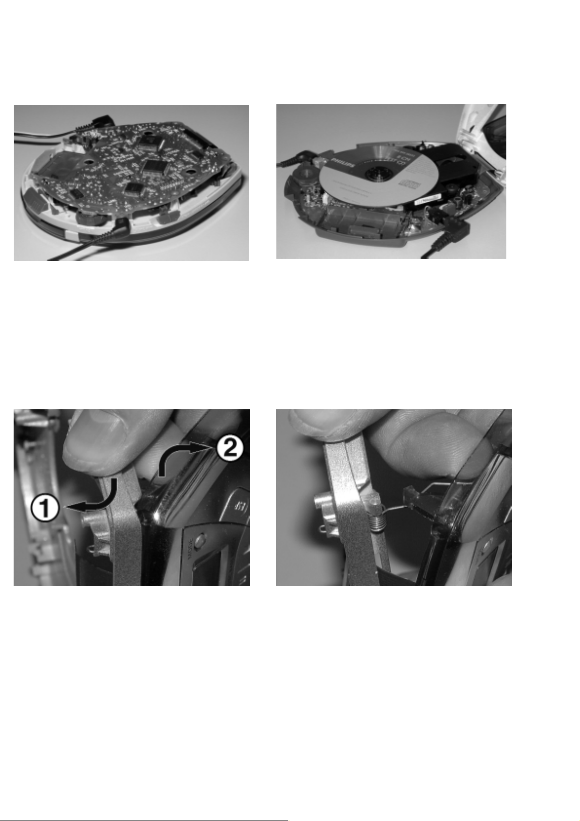
SERVICE HINTS
REPAIR POSITION COPPERSIDE
To get access to the copperside of the
printed board assembly proceed as follows:
1. Remove the bottom screws (6x)
2. Lift the bottom-cabinet
3. Supply the unit via external DC-socket
4. Take care that the door switch is closed during
measurements
To get access to the componentside of the
printed board assembly proceed as follows:
1. Remove the bottom screws (6x)
2. Open the CD-door
3. Lift the top-cabinet and put it backwards on the table
4. Supply the unit via the external DC-socket
5. Take care that the door switch is closed during
measurements
REPAIR POSITION COMPONENTSIDE
DISMANTLING THE CD-DOOR
To dismantle the CD-door proceed as follows:
1. Dismantle bottom and printed board/drive assembly
2. Disconnect membrane keyboard
(flex-foil connector on copperside of printed board)
3. Bend the cabinet leftwards downwards 1,
while bending the CD-door rightwards upwards 2
The procedure appears to be tricky at first, but force
needs to be applied with thumb and middle finger only.
It’s just like snapping one’s fingers.
Remark: Don’t worry about applied force - both parts have a
solid design. However, do not use screwdrivers or
tools like that. Sharp edges could damage hinge or
cabinet part.
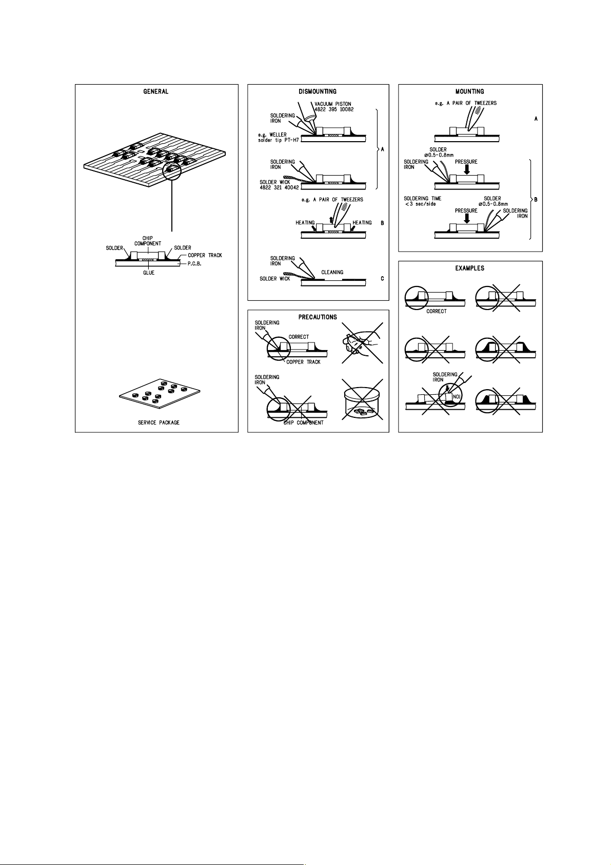
HANDLING CHIP COMPONENTS
SERVICE TOOLS
Audio signal disc SBC429 4822 397 30184
Playability test disc SBC444 4822 397 30245
Test disc 5 (disc without errors) + Test disc 5A (disc with dropout errors,
black spots and fingerprints) SBC426/SBC426A 4822 397 30096
ESD PROTECTION EQUIPMENT
Anti-static table mat large 1200x650x1.25mm 4822 466 10953
small 600x650x1.25mm 4822 466 10958
Anti-static wristband 4822 395 10223
Connection box (3 press stud connections, 1Mø) 4822 320 11307
Extendible cable (2m, 2Mø, to connect wristband to connection box) 4822 320 11305
Connecting cable (3m, 2Mø, to connect table mat to connection box) 4822 320 11306
Earth cable (1Mø, to connect any product to mat or to connection box) 4822 320 11308
KIT ESD3 (combining all 6 prior products - small table mat) 4822 310 10671
Wristband tester 4822 344 13999
2-2

PIN DESCRIPTION OF INTEGRATED CIRCUITS
TZA1024 – HF-PREAMPLIFIER AND LASER SUPPLY CIRCUIT
Pin Name Direction Description
–––––––––––––––––––––––––––––––––––––––––––––––––––––––––––––––––––––––––––––––––––––––––––––––––––––––––––
1 LD HF-preamp →CD-drive current output to laser diode
2 VCCL +2.6V laser supply voltage
3 CFIL → HF-preamp external filter capacitor
4 MON CD-drive → HF-preamp laser monitor diode input
5 DIN CD-drive → HF-preamp central diode input
6 GND GND ground
7 PWRON CD10 → HF-preamp power-on select input
8 CMFB +2.6V / 2 common mode feedback voltage input
9 RFFB → HF-preamp external RF feedback resistor
10 RFEQO HF-preamp → RF amplifier output
11 CDRW CD10 → HF-preamp gain select input for CDDA/CDRW
12 EQSEL CD10 → HF-preamp equalizer/speed select input
13 VCC2 +2.6V supply voltage
14 RGADJ GND external laser supply gain adjust resistor
SC111259FTA – SERVO DRIVER & POWER MANAGEMENT IC
Pin Name Direction Description
–––––––––––––––––––––––––––––––––––––––––––––––––––––––––––––––––––––––––––––––––––––––––––––––––––––––––––
1 SLEEP µP → servo driver sleep input
2 WAKW µP → servo driver wake input
3 VR +VR reference voltage input (motor driver)
4 ERR4 CD10 → servo driver control signal input (slide error signal)
5 CF4 → servo driver phase correction capacitor connect (CH4)
6 CF3 → servo driver phase correction capacitor connect (CH3)
7 ERR3 CD10 → servo driver control signal input (radial error signal)
8 ERR2 CD10/µP → servo driver control signal input (disc speed error signal)
9 CF2 → servo driver phase correction capacitor connect (CH2)
10 CF1 → servo driver phase correction capacitor connect (CH1)
11 ERR1 CD10 → servo driver control signal input (focus error signal)
12 OUT1A servo driver → CD-drive positive drive output (CH1)
13 PGND1 GND H-bridge driver ground
14 OUT1B servo driver → CD-drive negative drive output (CH1)
15 VIN12 +A CH1 and CH2 H-bridge driver supply voltage
16 OUT2B servo driver → CD-drive negative drive output (CH2)
17 PGND2 GND H-bridge driver ground
18 OUT2A servo driver → CD-drive positive drive output (CH2)
19 OUT3A servo driver → CD-drive positive drive output (CH3)
20 PGND2 GND H-bridge driver ground
21 OUT3B servo driver → CD-drive negative drive output (CH3)
22 VIN34 +A CH3 and CH4 H-bridge driver supply voltage
23 OUT4B servo driver → CD-drive negative drive output (CH4)
24 PGND4 GND H-bridge driver ground
25 OUT4A servo driver → CD-drive positive drive output (CH4)
26 VG +VG charge pump output
27 C2H → servo driver charge pump capacitor connect
28 C1H → servo driver charge pump capacitor connect
29 C1L → servo driver charge pump capacitor connect
30 C2L → servo driver charge pump capacitor connect
31 VIN battery → servo driver battery supply voltage
32 RSTB servo driver → reset block output
33 CHGSW servo driver → charge circuit transistor drive output for battery charger
34 RS charge circuit → servo driver OpAmp non-inverting input for battery charger
35 INM2 → servo driver error amplifier inverting input
36 RF2 → servo driver error amplifier output
37 DCIN +DC DC power supply from AC/DC adaptor
38 VDET servo driver → DCIN over voltage and VIN low voltage detect output
39 VREF servo driver → Voltage reference circuit output
40 DTC → servo driver max. duty control voltage input for power management
41 VOUT servo driver → DC/DC converter PWM output for power management
42 VC → servo driver power management power supply
43 CGND GND internal ground
44 RF1 servo driver → OpAmp output for power management
45 INM1 → servo driver OpAmp inverting input for power management
46 CLK → servo driver clock input
47 OE µP → servo driver output enable for motor drivers
48 CHGON µP → servo driver charge enable for battery charger
3-1
 Loading...