

Page 1
Video Cassette Recorder Deck: Turbo Drive APOLLO 13
VR120
/02/55/58
VR170/02/07/39/58
VR220/02/07/39/58
VR270B/02/07/39/58
VR270W/02/07/39/58
VR402/58
VR420/02/39/58
VR520/02/07/16/58
VR570/02/07/16/39/58
VR572/02/16
VR620/02/07/16/39/58
Contents Page
1 List of PWBs, Features, Technical specifications 3
2 Safety instructions, Modifications 10
3 Directions for use 12
4 Dismantling instructions 46
5 Service modes, Repair tips 49
6 Block diagrams, Waveforms, Wiring diagram 57
7 Circuit diagrams and PWB layouts 64
8 Electrical alignments 91
9 Circuit descriptions and List of abbreviations 97
10 Tape deck 113
11 Exploded views 124
12 Spare parts list 128
Survey of versions:
/02/03 PAL B/G, VPS/PDC
/05 PAL I, UK
/07 PAL I, Ireland
/11 PAL B/G, Belgium
/13 PAL B/G, Nordic
/16 PAL B/G, Spain / Nordic
/38/39 SECAM L, L’ & PAL B/G, I
/55 PAL B/G, I, PAL/SECAM D/K
/58/59 PAL/SECAM B/G, D/K
/60 PAL/SECAM D/K
©
Copyright 2001 Philips Consumer Electronics B.V. Eindhoven, The Netherlands.
All rights reserved. No part of this publication may be reproduced, st ored in a
retri eval system or transmitted, in any for m or by any means, elect ronic, mechani cal,
photocopyi ng, or otherwise without the prior permission of Philips.
VR622/02/16
VR627/02/16
VR670B/02/07/16
VR670B/39/58
VR670W/02/07/16
VR670W/39/58
VR720/02/07/16/39/58
VR870CC/02/07/16
VR870CC/39/58
VR870L/02/07/16
VR870L/39/58
Survey of remote controls:
VR220/02/07/39/58
VR420/02/39/58
VR870L/02/07/16/39/58
VR870CC/02/07/16/39/58
SB140/03
SB145/03/11
SB445/11
SB645/03/11
SB745/03/11
SB140/38
SB445/38
SB645/38
SB745/38
65DV30/39
45DV30/39
20DV30/39
VR120/02/16/55/58
VR402/58
VR520/02/07/16/58
VR170/07/39/58
VR270W/02/07/39/58
VR570/02/07/16/39/58
VR572/02/16
VR670W/02/07/16/39/58
VR270B/02/07/39/58
VR670B/02/07/16/39/58
VR620/02/07/16/39/58
VR622/02/16
VR627/02/16
VR720/02/07/16/39/58
SB140/03/38
SB145/03/11
SB445/11/38
SB645/03/11/38
SB745/03/11/38
20DV30/39
45DV30/39
65DV30/39
AA
RT112/111 8622 661 12111
RT114/111 8622 661 14111
RT116/201 8622 661 16201
RT116/204 8622 661 16204
RT121/101 8622 661 21101
RT121/111 8622 661 21111
RT121/121 8622 661 21121
RT123/111 8622 661 23111
RT128/112 8622 661 28112
Published by LE/MS0110, Videq Service Department Printed in Netherlands Subject to modification 5 3103 785 21760
Page 2

GB 2 VR120
2
4
Contents Page Contents Page
1 List of PWBs, Features, Technical
specifications 3
Survey of sets and PWB’s with software versions 3
Features 5
Technical specification 9
Safety instructions, Modifications 10
Safety instructions 10
Modifications 11
8 Electrical alignments 91
Measuring instruments 91
Setting instructions 91
Video signal processing (VS-SEC)91
Front End (FV)92
Deck electronics (DE)93
Servo System (AIO1)93
Audio Linear (AL)94
Display Control (AIO2)94
3 Direction for use 12
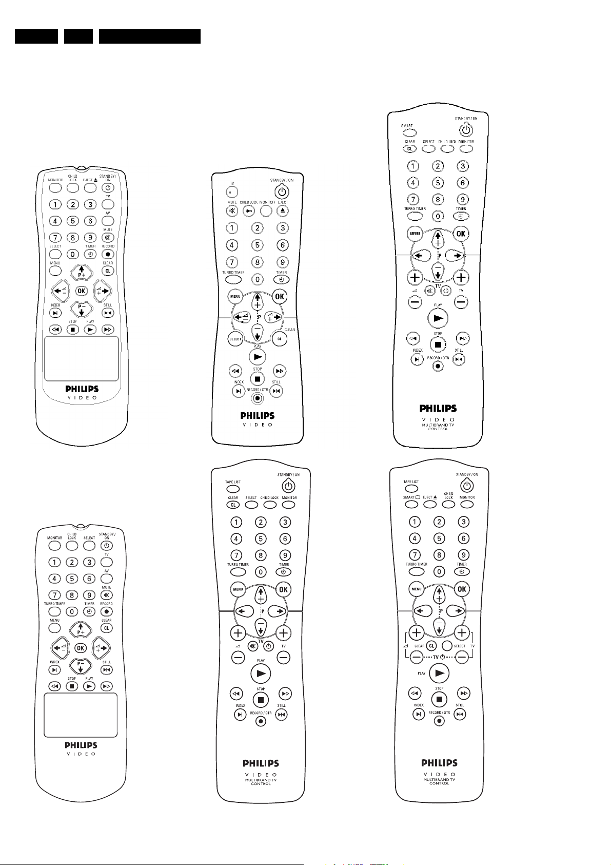
Remote control overview 12
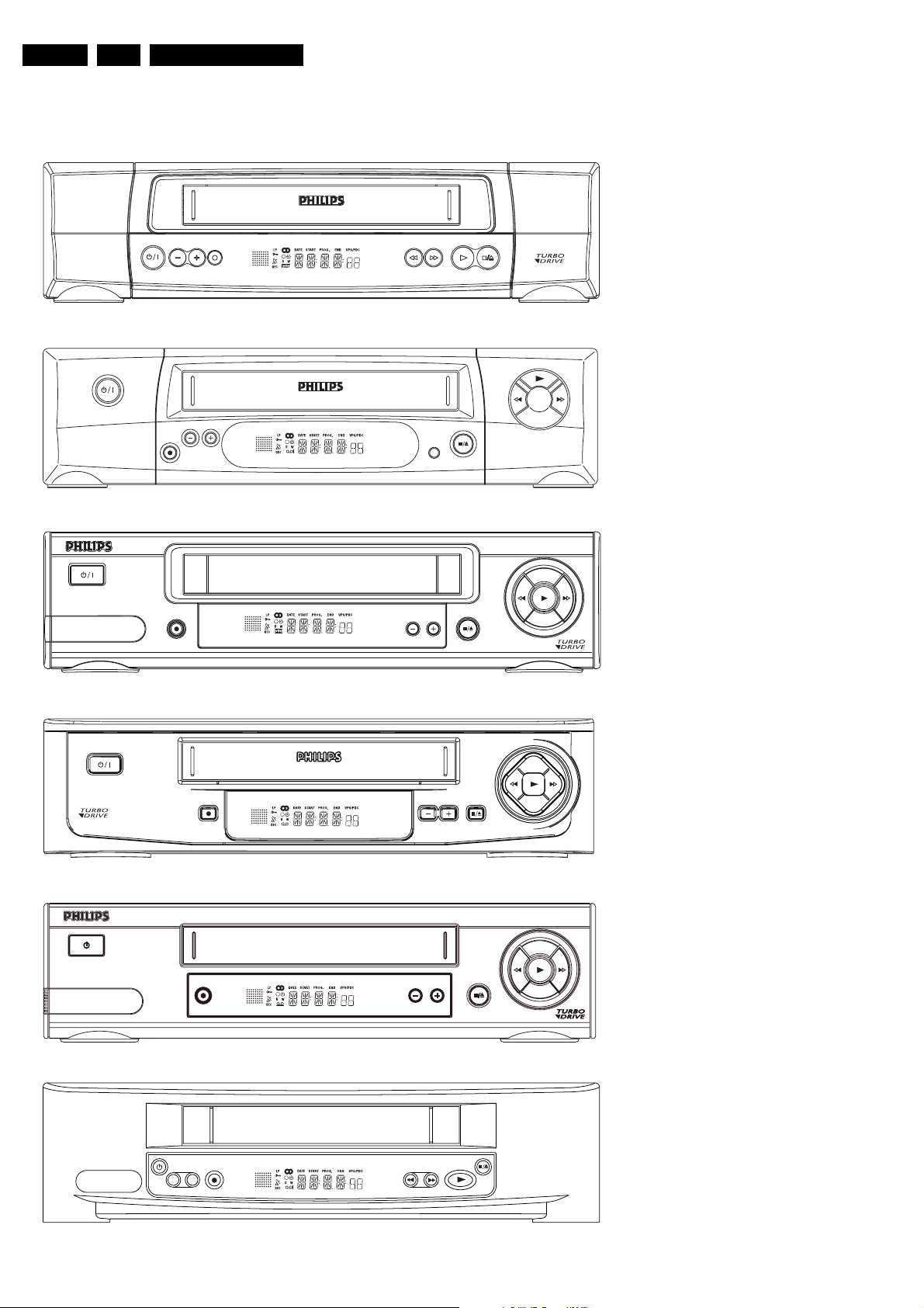
Front overview of the sets 14
Direction for use introduction 16
Remote control codes 45
Dismantling instructions 46
Dismantling instructions 46
Dismantling of the motherboard/drive
combination 47
Dismantling the drive 48
5 Service modes, Repair tips 49
Special functions 49
Service test program 49
Repair tips 53
6 Block diagrams, Waveforms, Wiring diagram 57
Block diagram Video 57
Block diagram Audio Mono 58
Block diagram Audio Stereo 59
Supply voltages and Bus diagram 60
Supply voltages and Bus diagram 61
Block diagram Central Control 62
Waveforms 63
7 Circuit diagrams and PWB layouts 64
Power supply (PS)64
Display control (AIO2)65
Central control (AIO1)66
Deck control (DE)67
Variant List Frontend (FV)68
Frontend (FV)69
FM stereo (FM-ST)70
FM Stereo + Nicam (FM-ST-NIC)71
Audio Linear (AL) 72
FM - Audio (AF)73
Video Signal Processing - SECAM (VS-SEC)74
Video Signal Processing (VS)75
VPS/PDC & OSD Part (VPO)76
In/Out Part (IO)77
FOLLOW ME Part (FOME)78
Wiring Diagram 79
Mother board - solder side 80
Mother board - component side 83
Connector print (ACP10)84
Connector print (ACP1)84
Connector print (QBOE1)85
Connector print (QBOG1)85
Connector print (ACP35)86
Key print (AKP35)87
Illumination print (AKP13)88
Key print (AKP36) 89
Shuttle board (ASP10)89
Shuttle board (QKP21)89
Test point overview 90
9 Circuit descriptions and List of
10 Tape deck 113
11 Exploded views 124
12 Spare parts list 128
abbreviations 97
Switched-mode power supply PS (PS Part) 97
Operating unit (DC part) 98
Central Control (AIO part) 99
Deck electronics (DE part) 100
Front end (FV part) 101
Video signal processing VS (VS part) 102
Audio linear (AL part) 104
Audio HiFi - for stereo units (AF part) 105
IN/OUT (IO part) 105
Follow Me (FOME part) 106
VPS/PDC, on-screen display (VPO part) 106
Simple Blockdiagram 107
Simple Blockdiagram FM Audio / Linear Audio
processing 109
List of abbreviations 110
Drive assembly 113
Adjustments 117
Deck exploded view (TOP) 120
Deck exploded view (BOTTOM) 121
Mechanical parts list 122
Exploded view set 124
Page 3
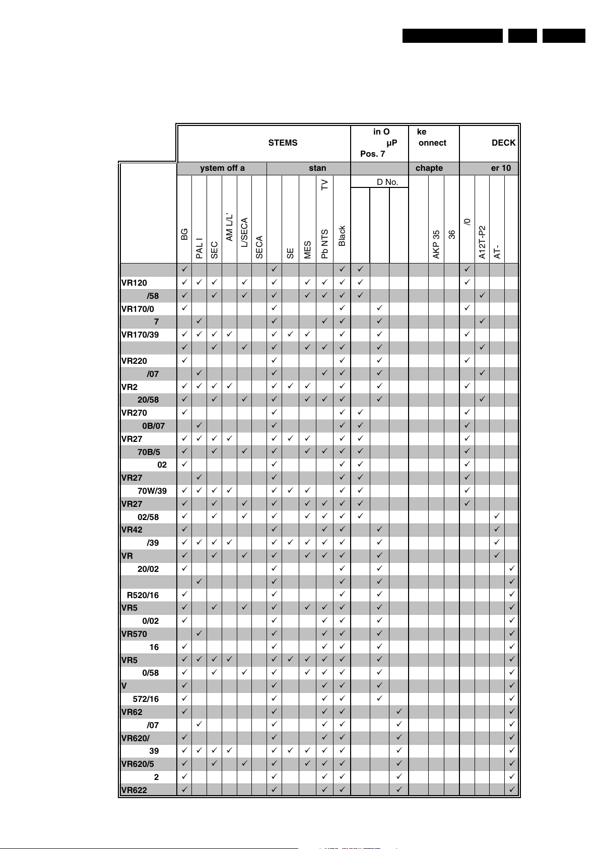
List of PWBs, Features, Technical specifications
1. List of PWBs, Features, Technical specifications
1.1 Survey of sets and PWB’s with software versions
GB 3VR120 1.
VR120/02
VR120/55
VR120/58
VR170/02
VR170/07
VR170/39
VR170/58
VR220/02
VR220/07
VR220/39
VR220/58
VR270B/02
VR270B/07
VR270B/39
VR270B/58
VR270W/02
VR270W/07
VR270W/39
VR270W/58
VR402/58
VR420/02
VR420/39
VR420/58
VR520/02
VR520/07
VR520/16
VR520/58
VR570/02
VR570/07
VR570/16
VR570/39
VR570/58
VR572/02
VR572/16
VR620/02
VR620/07
VR620/16
VR620/39
VR620/58
VR622/02
VR622/16
All in One-
(AIO) µP
Pos. 7899
31
Pb Black & White
MoboSystem off air
µP-ID No.
32 37
AC3P1 - xU
AC3B1 - xU
Rec/Pb standard
MESECAM
PAL BG
SECAM BG
PAL I
áááá á
ááááá áááá á
áááá áááá á
ááááá
ááááá á
áááá á á á á á á
áááá ááá á á
ááááá
ááááá á
áááá á á á á á á
áááá ááá á á
áááá á
áááá á
áááá á á á á á á
áááá áááá á
áááá á
áááá á
áááá á á á á á á
áááá áááá á
áááá áááá á
ááááá á
áááá ááááá á á
áááá ááá á á
áááá á
áááá á
áááá á
áááá ááá á á
ááááá á
ááááá á
ááááá á
áááá ááááá á á
áááá ááá á á
ááááá á
ááááá á
ááááá á
ááááá á
ááááá á
áááá ááááá á á
áááá ááá á á
ááááá á
ááááá á
PAL/SECAM DK
SECAM L/L’
SECAM K1
PAL
SECAM
Pb NTSC on PAL TV
key print
connector
print
chapter 7
ACP 35
AC3P7 - xU
AKP 35
AKP 36
TAPE DECK SYSTEMS
chapter 10
A12T-P2/0
A12T-P2/0LP
AT-S4/2
AT-S4/0
Page 4
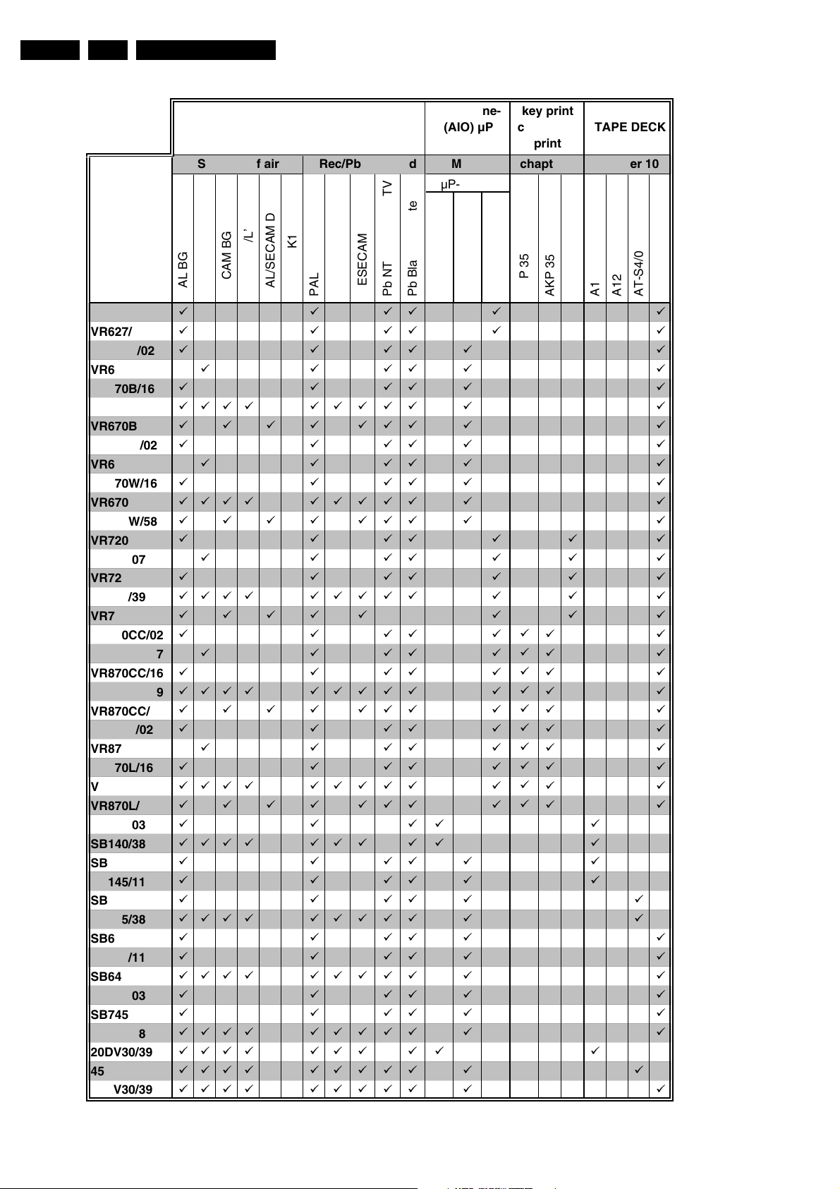
GB 4 VR1201.
List of PWBs, Features, Technical specifications
VR627/02
VR627/16
VR670B/02
VR670B/07
VR670B/16
VR670B/39
VR670B/58
VR670W/02
VR670W/07
VR670W/16
VR670W/39
VR670W/58
VR720/02
VR720/07
VR720/16
VR720/39
VR720/58
VR870CC/02
VR870CC/07
VR870CC/16
VR870CC/39
VR870CC/58
VR870L/02
VR870L/07
VR870L/16
VR870L/39
VR870L/58
SB140/03
SB140/38
SB145/03
SB145/11
SB445/11
SB445/38
SB645/03
SB645/11
SB645/38
SB745/03
SB745/11
SB745/38
20DV30/39
45DV30/39
65DV30/39
All in One-
SYSTEMS TAPE DECK
System off air Mobo chapter 10
PAL BG
PAL I
SECAM BG
SECAM L/L’
ááááá á
ááááá á
ááááá á
ááááá á
ááááá á
áááá ááááá á á
áááá ááá á á
ááááá á
ááááá á
ááááá á
áááá ááááá á á
áááá ááá á á
ááááááá
ááááááá
ááááááá
áááá ááááá á á á
áááá á á á á
ááááááá
ááááááá
ááááááá
áááá ááááá á á á
áááá ááá á á á
ááááááá
ááááááá
ááááááá
áááá ááááá á á á
áááá ááá á á á
áááá á
áááá á á á á á á
áááááá
áááááá
ááááá á
áááá ááááá á á
ááááá á
ááááá á
áááá ááááá á á
ááááá á
ááááá á
áááá ááááá á á
áááá á á á á á á
áááá ááááá á á
áááá ááááá á á
Rec/Pb standard chapter 7
MESECAM
PAL/SECAM DK
SECAM K1
PAL
SECAM
Pb NTSC on PAL TV
Pos. 7899
31
Pb Black & White
(AIO) µP
µP-ID No.
32 37
AC3P1 - xU
AC3B1 - xU
key print
connector
print
ACP 35
AC3P7 - xU
á
á
á
á
á
á
á
á
á
á
AKP 35
AKP 36
A12T-P2/0LP
AT-S4/0
A12T-P2/0
AT-S4/2
Page 5
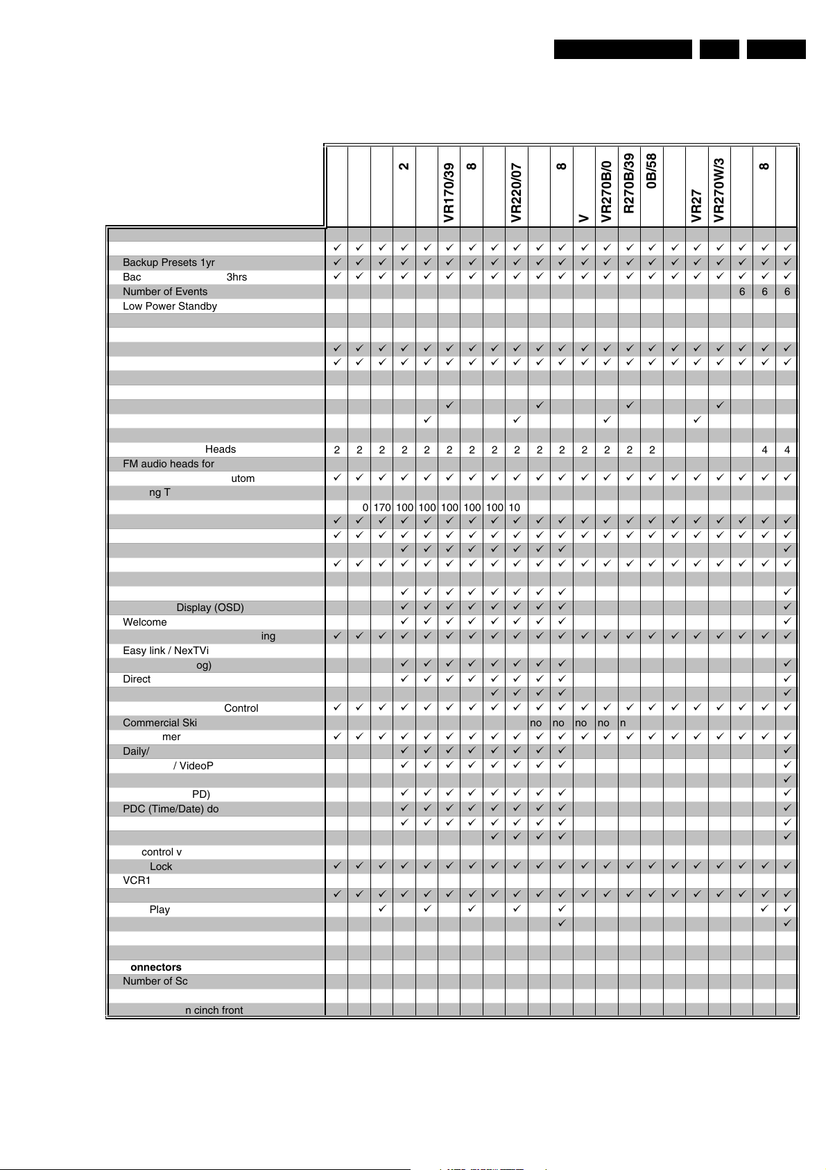
List of PWBs, Features, Technical specifications
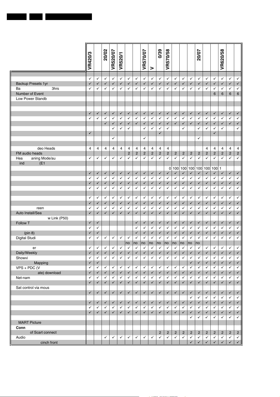
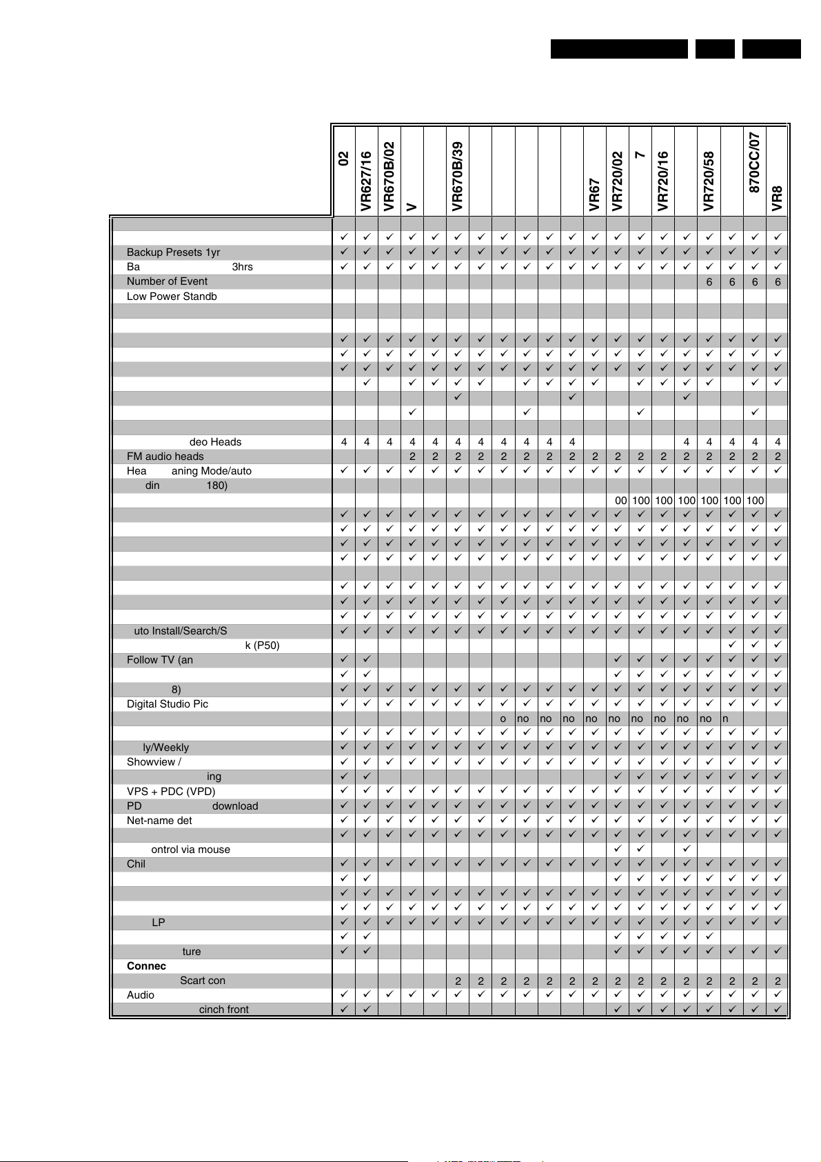
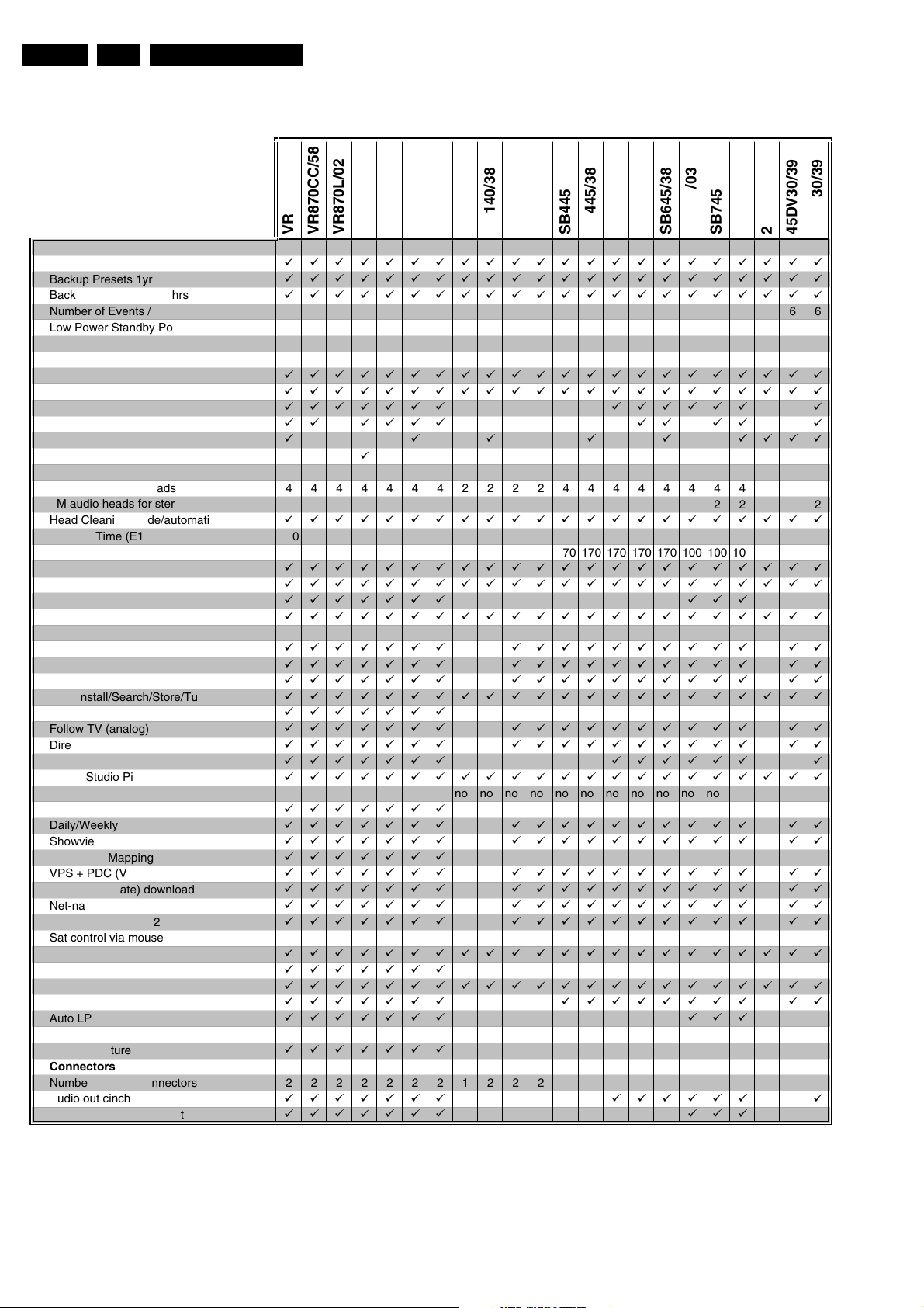
1.2 Features
VR220/07
VR120/02
VR120/55
VR120/58
General
Auto Standby On/Off
Backup Presets 1yr
Backup Clock / Timer 3hrs
Number of Events / month
Low Power Standby Power Cons. [Watts] <4 <4 <4 <4 <4 <4 <4 <4 <4 <4 <4 <4 <4 <4 <4 <4 <4 <4 <4 <4 <4
Tuning - presets (only channel input)
Systems
Hyperband, UHF, VHF
Mono
German Stereo
NICAM
Splitter
Auto Seek
Mechanism
Number of Video Heads
FM audio heads for stereo
Head Cleaning Mode/automatic
Winding Time (E180) sec
Rewind Time (E180) sec
Quick View
Tape Counter lin. Relative (h.m.s.)
Tape Counter Time Left (h.m)
VISS: next/prev. index / blank tape search
Features
Plug & Play
On Screen Display (OSD)
Welcome Screen
Auto Install/Search/Store/Tuning
Easy link / NexTView Link (P50)
Follow TV (analog)
Direct Record
16:9 (pin 8)
Digital Studio Picture Control
Commercial Skip no no no no no no no no no no no no no no no no no no no no no
Turbo Timer
Daily/Weekly
Showview / VideoPlus+
ShowView Mapping
VPS + PDC (VPD)
PDC (Time/Date) download
Net-name detection
Record Link / Scart 2
Sat control via Mouse
Child Lock
VCR1/VCR2
OTR
Long Play
Auto LP
Tape List
SMART Picture
Connectors
Number of Scart connectors
Audio out cinch rear
Audio/Video in cinch front
ббббббббббббббббббббб
ббббббббббббббббббббб
ббббббббббббббббббббб
666666666666666666666
99 99 99 99 99 99 99 99 99 99 99 99 99 99 99 99 99 99 99 99 99
ббббббббббббббббббббб
ббббббббббббббббббббб
222222222222222222244
ббббббббббббббббббббб
260 260 260 100 100 100 100 100 100 100 100 260 260 260 260 260 260 260 260 260 100
170 170 170 100 100 100 100 100 100 100 100 170 170 170 170 170 170 170 170 170 100
ббббббббббббббббббббб
ббббббббббббббббббббб
ббббббббббббббббббббб
ббббббббббббббббббббб
ббббббббббббббббббббб
ббббббббббббббббббббб
ббббббббббббббббббббб
ббббббббббббббббббббб
ббббб áá
111222222221121112112
VR170/07
VR170/02
áááá
бббббббб á
бббббббб á
бббббббб á
бббббббб á
бббббббб á
бббббббб á
бббббббб á
бббббббб á
бббббббб á
бббббббб á
бббббббб á
VR170/58
VR170/39
áááá
VR220/02
áááá á
áááá á
VR220/39
VR220/58
áá
VR270B/02
VR270B/07
VR270B/39
VR270B/58
VR270W/02
VR270W/07
VR270W/39
VR270W/58
GB 5VR120 1.
VR402/58
VR420/02
á
Page 6
GB 6 VR1201.
General
Auto Standby On/Off
Backup Presets 1yr
Backup Clock / Timer 3hrs
Number of Events / month
Low Power Standby Power Cons. [Watts] <4 <4 <4 <4 <4 <4 <4 <4 <4 <4 <4 <4 <4 <4 <4 <4 <4 <4 <4 <4
Tuning - presets (only channel input)
Systems
Hyperband, VHF, UHF
Mono
German Stereo
NICAM
Splitter
Auto Seek
Mechanism
Number of Video Heads
FM audio heads for stereo
Head Cleaning Mode/automatic
Winding Time (E180) sec
Rewind Time (E180) sec
Quick View
Tape Counter lin. Relative (h.m.s.)
Tape Counter Time Left (h.m)
VISS: next/prev. index / blank tape search
Features
Plug & Play
On Screen Display (OSD)
Welcome Screen
Auto Install/Search/Store/Tuning
Easy link / NexTView Link (P50)
Follow TV (analog)
Direct Record
16:9 (pin 8)
Digital Studio Picture Control
Commercial Skip no no no no no no no no no no no no no no no no no no no no
Turbo Timer
Daily/Weekly
Showview / VideoPlus+
ShowView Mapping
VPS + PDC (VPD)
PDC (Time/Date) download
Net-name detection
Record Link / Scart 2
Sat control via mouse
Child Lock
VCR1/VCR2
OTR
Long Play
Auto LP
Tape List
SMART Picture
Connectors
Number of Scart connectors
Audio out cinch rear
Audio/Video in cinch front
List of PWBs, Features, Technical specifications
VR570/07
VR420/39
VR420/58
бббббббббббббббббббб
бббббббббббббббббббб
бббббббббббббббббббб
66666666666666666666
99 99 99 99 99 99 99 99 99 99 99 99 99 99 99 99 99 99 99 99
бббббббббббббббббббб
бббббббббббббббббббб
ááá
44444444444444444444
бббббббббббббббббббб
100 100 100 100 100 100 100 100 100 100 100 100 100 100 100 100 100 100 100 100
100 100 100 100 100 100 100 100 100 100 100 100 100 100 100 100 100 100 100 100
бббббббббббббббббббб
бббббббббббббббббббб
бббббббббббббббббббб
бббббббббббббббббббб
бббббббббббббббббббб
бббббббббббббббббббб
бббббббббббббббббббб
бббббббббббббббббббб
áá бббббббббббббб
áá бббббббббббббб
áá бббббббббббббб
бббббббббббббббббббб
бббббббббббббббббббб
бббббббббббббббббббб
бббббббббббббббббббб
áá ббббббб
бббббббббббббббббббб
бббббббббббббббббббб
бббббббббббббббббббб
бббббббббббббббббббб
бббббббббббббббббббб
бббббббббббббббббббб
бббббббббббббббббббб
бббббббббббббббббббб
22222222222222222222
VR520/07
VR520/02
бббббббббббббббббб
222222222222222222
бббббббббббббббббб
VR520/16
VR520/58
VR570/02
ááá áááá á áááá á
áá á
VR570/16
VR570/39
VR570/58
VR572/16
VR572/02
VR620/02
ббббббб
ббббббб
ббббббб
VR620/16
VR620/07
VR620/39
VR620/58
VR622/16
VR622/02
Page 7
List of PWBs, Features, Technical specifications
VR670B/39
VR627/02
VR627/16
VR670B/02
General
Auto Standby On/Off
Backup Presets 1yr
Backup Clock / Timer 3hrs
Number of Events / month
Low Power Standby Power Cons. [Watts] <4 <4 <4 <4 <4 <4 <4 <4 <4 <4 <4 <4 <4 <4 <4 <4 <4 <4 <4 <4
Tuning - presets (only channel input)
Systems
Hyperband, UHF, VHF
Mono
German Stereo
NICAM
Splitter
Auto Seek
Mechanism
Number of Video Heads
FM audio heads for stereo
Head Cleaning Mode/automatic
Winding Time (E180) sec 100 100 100 100 100 100 100 100 100 100 100 100 100 100 100 100 100 100 100 100
Rewind Time (E180) sec 100 100 100 100 100 100 100 100 100 100 100 100 100 100 100 100 100 100 100 100
Quick View
Tape Counter lin. Relative (h.m.s.)
Tape Counter Time Left (h.m)
VISS: next/prev. index / blank tape search
Features
Plug & Play
On Screen Display (OSD)
Welcome Screen
Auto Install/Search/Store/Tuning
Easy link / NexTView Link (P50)
Follow TV (analog)
Direct Record
16:9 (pin 8)
Digital Studio Picture Control
Commercial Skip no no no no no no no no no no no no no no no no no no no no
Turbo Timer
Daily/Weekly
Showview / VideoPlus+
ShowView Mapping
VPS + PDC (VPD)
PDC (Time/Date) download
Net-name detection
Record Link / Scart 2
Sat control via mouse
Child Lock
VCR1/VCR2
OTR
Long Play
Auto LP
Tape List
SMART Picture
Connectors
Number of Scart connectors
Audio out cinch rear
Audio/Video in cinch front
бббббббббббббббббббб
бббббббббббббббббббб
бббббббббббббббббббб
66666666666666666666
99 99 99 99 99 99 99 99 99 99 99 99 99 99 99 99 99 99 99 99
бббббббббббббббббббб
бббббббббббббббббббб
бббббббббббббббббббб
á áááá áááá áááá áá
44444444444444444444
22222222222222222222
бббббббббббббббббббб
бббббббббббббббббббб
бббббббббббббббббббб
бббббббббббббббббббб
бббббббббббббббббббб
бббббббббббббббббббб
бббббббббббббббббббб
бббббббббббббббббббб
бббббббббббббббббббб
áá бббббббб
áá бббббббб
бббббббббббббббббббб
бббббббббббббббббббб
бббббббббббббббббббб
бббббббббббббббббббб
бббббббббббббббббббб
áá бббббббб
бббббббббббббббббббб
бббббббббббббббббббб
бббббббббббббббббббб
бббббббббббббббббббб
бббббббббббббббббббб
áá бббббббб
бббббббббббббббббббб
бббббббббббббббббббб
бббббббббббббббббббб
áá ббббб
áá бббббббб
22222222222222222222
бббббббббббббббббббб
áá бббббббб
VR670B/16
VR670B/07
áááá
VR670B/58
VR670W/02
ááá
VR670W/07
VR670W/16
VR670W/39
VR670W/58
áá á
VR720/07
VR720/02
VR720/16
VR720/39
GB 7VR120 1.
VR870CC/02
VR720/58
ááá
VR870CC/07
VR870CC/16
Page 8
GB 8 VR1201.
General
Auto Standby On/Off
Backup Presets 1yr
Backup Clock / Timer 3hrs
Number of Events / month
Low Power Standby Power Cons. [Watts] <4 <4 <4 <4 <4 <4 <4 <4 <4 <4 <4 <4 <4 <4 <4 <4 <4 <4 <4 <4 <4 <4
Tuning - presets (only channel input)
Systems
Hyperband, UHF, VHF
Mono
German Stereo
NICAM
Splitter
Auto Seek
Mechanism
Number of Video Heads
FM audio heads for stereo
Head Cleaning Mode/automatic
Winding Time (E180) sec 100 100 100 100 100 100 100 260 260 260 260 260 260 260 260 260 100 100 100 260 260 260
Rewind Time (E180) sec 100 100 100 100 100 100 100 170 170 170 170 170 170 170 170 170 100 100 100 170 170 170
Quick View
Tape Counter lin. Relative (h.m.s.)
Tape Counter Time Left (h.m)
VISS: next/prev. index / blank tape search
Features
Plug & Play
On Screen Display (OSD)
Welcome Screen
Auto Install/Search/Store/Tuning
easy link / NexTView Link (P50)
Follow TV (analog)
Direct Record
16:9 (pin 8)
Digital Studio Picture Control
Commercial Skip no no no no no no no no no no no no no no no no no no no no no no
Turbo Timer
Daily/Weekly
Showview / VideoPlus+
ShowView Mapping
VPS + PDC (VPD)
PDC (Time/Date) download
Net-name detection
Record Link / Scart 2
Sat control via mouse
Child Lock
VCR1/VCR2
OTR
Long Play
Auto LP
Tape List
SMART Picture
Connectors
Number of Scart connectors
Audio out cinch rear
Audio/Video in cinch front
List of PWBs, Features, Technical specifications
VR870CC/58
VR870CC/39
бббббббббббббббббббббб
бббббббббббббббббббббб
бббббббббббббббббббббб
6666666666666666666666
99 99 99 99 99 99 99 99 99 99 99 99 99 99 99 99 99 99 99 99 99 99
бббббббббббббббббббббб
бббббббббббббббббббббб
ббббббб бббббб á
áá áááá áá áá á
á á á á á áááá
4444444222244444444244
2222222 222222 2
бббббббббббббббббббббб
бббббббббббббббббббббб
бббббббббббббббббббббб
ббббббб ááá
бббббббббббббббббббббб
ббббббб бббббббббб áá
ббббббб бббббббббб áá
ббббббб бббббббббб áá
бббббббббббббббббббббб
ббббббб
ббббббб бббббббббб áá
ббббббб бббббббббб áá
ббббббб бббббб á
бббббббббббббббббббббб
ббббббб
ббббббб бббббббббб áá
ббббббб бббббббббб áá
ббббббб
ббббббб бббббббббб áá
ббббббб бббббббббб áá
ббббббб бббббббббб áá
ббббббб бббббббббб áá
бббббббббббббббббббббб
ббббббб
бббббббббббббббббббббб
ббббббб бббббббб áá
ббббббб ááá
ббббббб
2222222122222222222222
ббббббб бббббб á
ббббббб ááá
VR870L/02
VR870L/07
á
VR870L/16
VR870L/39
VR870L/58
SB140/03
SB140/38
SB145/03
SB145/11
SB445/11
SB445/38
SB645/03
SB645/11
SB645/38
SB745/03
SB745/11
SB745/38
20DV30/39
65DV30/39
45DV30/39
Page 9

List of PWBs, Features, Technical specifications
GB 9VR120 1.
1.3 Technical specification
Mains voltage : 220 - 240 V, +/- 10%
Mains frequency : 45 - 65 Hz
Power consumption : mono 12.5 W during
without Low Power Standby : mono 4 W during
with Low Power Standby : < 4 W standby
Ambient temperature : +10°C to +35°C
Relative humidity : 20 - 80 %
Dimensions : 380 x 260 x 94 mm
Weight : 3,7 kg
Fast forward/rewind time (turbo) : typ. 100s (E180
Position of use : horizontally, max.
Video resolution : ≥240 lines
Audio SP: Linear Audio : 80Hz - 10kHz (±6
Audio LP: Linear Audio : 80Hz - 5kHz (±6
Stereo FM Audio : 20Hz - 20kHz
Euroconnector (AV1) SCART plug 1
Connection to TV, monitor, projection TV ...
Pin 1 ARO (audio right out) 500 mV
Pin 2 ARI (audio right in) 0,2 V
Pin 3 ALO (audio left out) 500 mV
Pin 6 ALI (audio left in) 0,2 V
rms
rms
rms
rms
Pin 7 Blue (out) **)
Pin 8 Switching output: (with R
load
low: 2 V
high: 9.5 V
rise time: 5 ms
Pin 11 Green (out) **)
Pin 15 Red (out) **)
Pin 16 Blanking (out) **) loop through enabled during
standby, view-mode
Pin 19 CVBS II (video out) 1 V
Pin 20 CVBS I (video in) 1 V
+1/-2dB R
pp
+3/-3dB Rin75 Ohm
pp
**) passive loop through from AV2
operation
: HiFi 16 W during
operation
standby
: HiFi 4.4 W during
standby
cass.)
15°
dB)
dB)
(±3dB)
+/- 3 dB R
to 2V
+/- 3 dB R
to 2 V
out
Rin10 kOhm
rms
out
Rin10 kOhm
rms
= 10kOhm, C
out
load
1kOhm
1kOhm
<2nF)
75 Ohm
Cinch Audio/Video input on front panel (OPTION)
Audio:
AINFR (audio right in) red 0.2 V
AINFL (audio left in) white 0.2 V
rms
rms
to 2 V
to 2 V
typ. 500 mV
rms
typ. 500 mV
rms
Input impedance 47 kOhm
Video:
VFR yellow 1 Vpp + 3 / -3 dB
Input impedance 75 Ohm
Cinch Audio Out Rear (OPTION)
AOUT1R (audio right out) red 500 mV
AOUT1L (audio left out) white 500 mV
+/- 3 dB R
rms
+/- 3 dB R
rms
1 kOhm
out
1 kOhm
out
This outputs are in parallel with the corresponding outputs on
Euroconnector 1.
TUMOD
Modulator:
Frequency range loop through 45 MHz - 860 MHz
Gain: ANT IN - TV OUT 2 dB + 3 / -2 dB
ANT IN - TUN OUT 2 dB + 3 / -2 dB
Switch for RF input attenuation NO
Frequency range out (tuned by IIC bus) Ch 21 - Ch55
Tuner:
Frequency range 43 MHz - 860 MHz
for UK 450 MHz - 860MHz
Input voltage max. < 100 dBµV
min. > 60 dBµV
rms
rms
Euroconnector (AV2) SCART plug 2
Connection to decoder, SAT tuner, video disc, 2nd VCR ...
rms
rms
rms
to 2V
rms
to 2 V
+/- 3 dB R
Rin10 kOhm
rms
+/- 3 dB R
Rin10 kOhm
rms
out
out
Pin 1 ARO (audio right out) 500 mV
Pin 2 ARI (audio right in) 0,2 V
Pin 3 ALO (audio left out) 500 mV
Pin 6 ALI (audio left in) 0,2 V
Pin 7 Blue (out) **)
Pin 8 Switching input only: low: 2 V (low) R
high: 4.5 V (high) R
in
in
Pin 11 Green (in) *)
Pin 15 Red (in) *)
Pin 16 Blanking (in) *) loop through enabled during
standby, view-mode
Pin 19 CVBS II (video out) 1 V
Pin 20 CVBS I (video in) 1 V
+1/-2dB R
pp
+3/-3dB Rin75 Ohm
pp
75 Ohm
out
*) passive loop through to Euroconnector AV1
1kOhm
1kOhm
10 kOhm
10 kOhm
Page 10

GB 10 VR1202.
Safety instructions, Modifications
2. Safety instructions, Modifications
2.1 Safety instructions
• Safety regulations demand that the set be restored to its
original condition and that components identical with the
original types be used.
• Safety components are marked by the symbol h
• All ICs and many other semi-conductors are susceptible
to electrostatic discharges (ESD). Careless handling
during repair may reduce life drastically. When repairing,
make sure that you are conneted with the same potential
as the mass of the set via a wrist wrap with resistance.
Keep components and tools on the same potential.
• A set to be repaired should always be connected to the
mains via a suitable isolating transformer.
• Never replace any modules or any other parts while the
set is switched on.
• Use plastic instead of metal alignment tools. This in order
to prelude short-circuit or to prevent a specific circuit from
being rendered unstable.
Engineer's remarks:
2.1.1 Remarks
• The direct voltages and oscillograms ought to be
measured relative to the set mass.
• The direct voltages and oscillograms mentioned in the
diagrams ought to be measured with a colour bar signal
and the picture carrier at 503.25 MHz (C25).
• The oscillograms and direct voltages have been
measured in RECORD or PLAY mode.
• The semiconductors, which are mentioned in the circuit
diagram and in the parts lists, are fully exchangeable per
position with the semiconductors in the set, irrespective
of the type designation of these semiconductors.
Page 11
Safety instructions, Modifications
MADE IN EUROPE
MODEL NO:
VN 37 123456
SHOWVIEW IS
A TRADEMARK
APPLIED
GEMST
AR DEVELOPMENT
CORP
.
FOR
BY GEMST
AR
DEVELOPMENT
CORP
.
SHOWVIEW
SYSTEM
IS MANUF
ACTURED
UNDER
LICENSE
FROM
y
GB 11VR120 2.
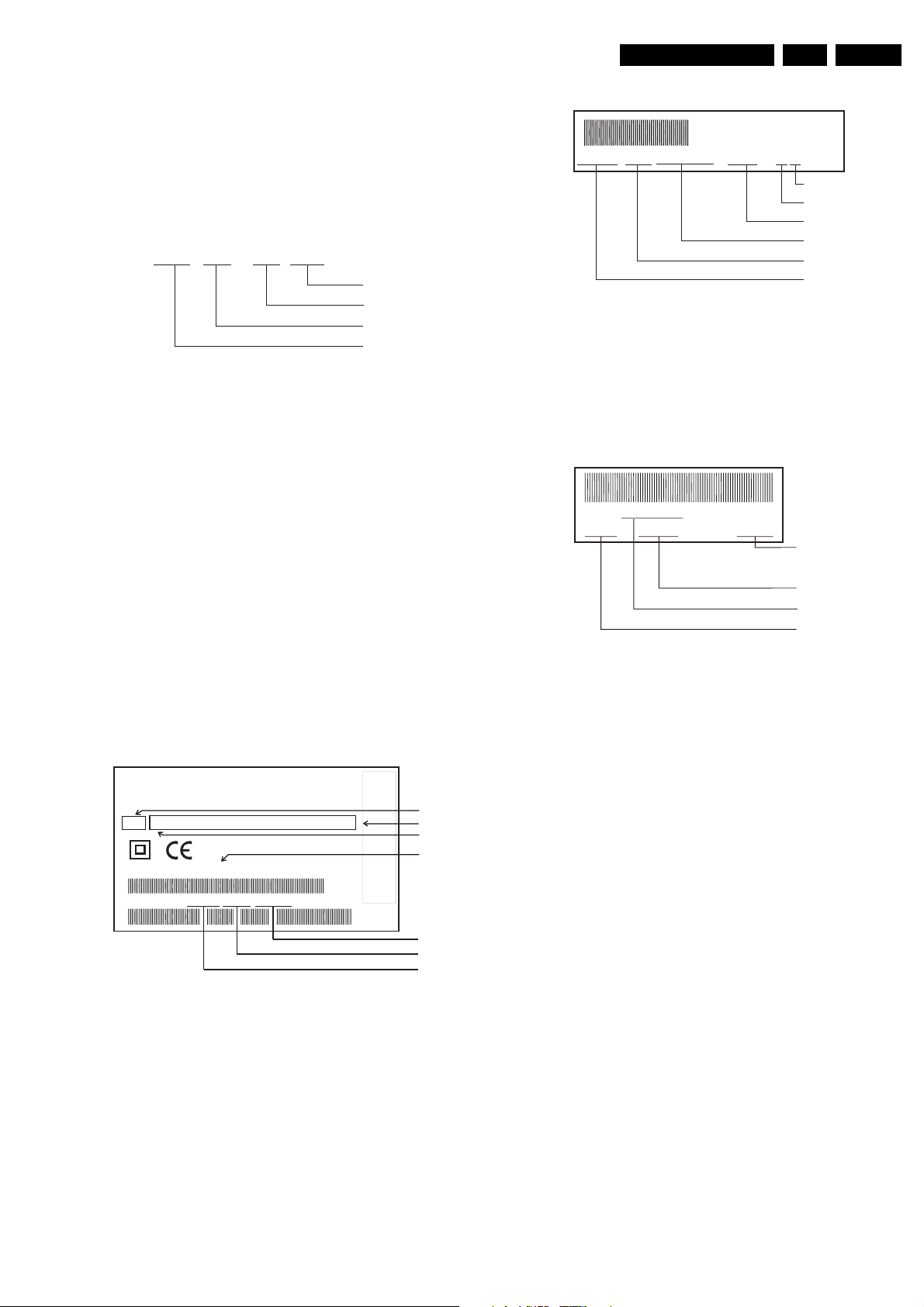
2.2 Modifications
2.2.1 Updating the service manual
All modifications and/or supplements to the Service Manual
are published by means of Service Information bulletins.
Each Service Information is numbered:
VR 01 - 01 GB
Language
Sequence number
Year
A Service Information bulletin consists of a front page which,
if needed, is followed by supplementary and/or replacement
sheets.
Replacement sheets should replace existing sheets in the
Service Manual. These sheets are identified by an additional
letter after the page number.
Example: Page 5-1a replaces page 5-1 in the Service
Manual.
Supplementary sheets should be inserted between existing
sheets in the Service Manual. These sheets are identified by
an additional figure after the page number.
Example: Page 5-1-1 should be inserted after page 5-1.
2.2.2 Modifications in the set
Tape deck
12345678 10001 A12T-P2/0LP
011731 12WD44
Production code
Factory indication
Production date
Tape deck type
Factory deck number
Note:
• The production code and the serial number on the tape
deck do not correspond to the production code and the
serial number on the type plate.
Printed circuits
The sticker is generally located on the copper side of the
board.
Example:
AVR 01102
12345 KW 015 123456
Serial number
Production week
Printed boardname
Factor
code
All important parts of the set (such as the tape deck, the
printed circuits and modules) are equiped with a sticker.
Those stickers provide a number of important information.
Type plate
The type plate is located on the back cover.
220-240 V ~
A13
AA
MODEL NO:
PROD.NO:
Note:
• In case of an important change in the set, the production
• In case of a major change in the set, the evolution code
.
MADE IN EUROPE
50Hz
AAA BBB CCC DDD EEE FFF GGG
VR120/02
VN 37 0015 123456
.
CORP
APPLIED
CORP
ACTURED
FROM
IS MANUF
DEVELOPMENT
LICENSE
A TRADEMARK
AR
AR DEVELOPMENT
SYSTEM
UNDER
GEMST
BY GEMST
SHOWVIEW IS
SHOWVIEW
FOR
Range
Option codes (A-G)
Evolution code
Type number
Serial number
Production date
Production center (VN),
Production code
code on the type plate is incremented: E.g. 37 becomes
38.
is incremented: E.g. AA becomes AB.
Note:
• The production code number might not always be
mentioned.
In case of an important modification, the last figure of the
factory code number (point number) is increased by one: E.g.
8502.1 becomes 8502.2
Page 12
GB 12 VR1203.
3. Direction for use
Direction for use
RT111
RT116
RT112
RT114
RT121
RT123
RT128
Page 13

Remote control
Direction for use
GB 13VR120 3.
SMART
STANDBY/ON m
CLEAR (CL)
SELECT
CHILD LOCK
MONITOR
TURBO TIMER
TIMER k
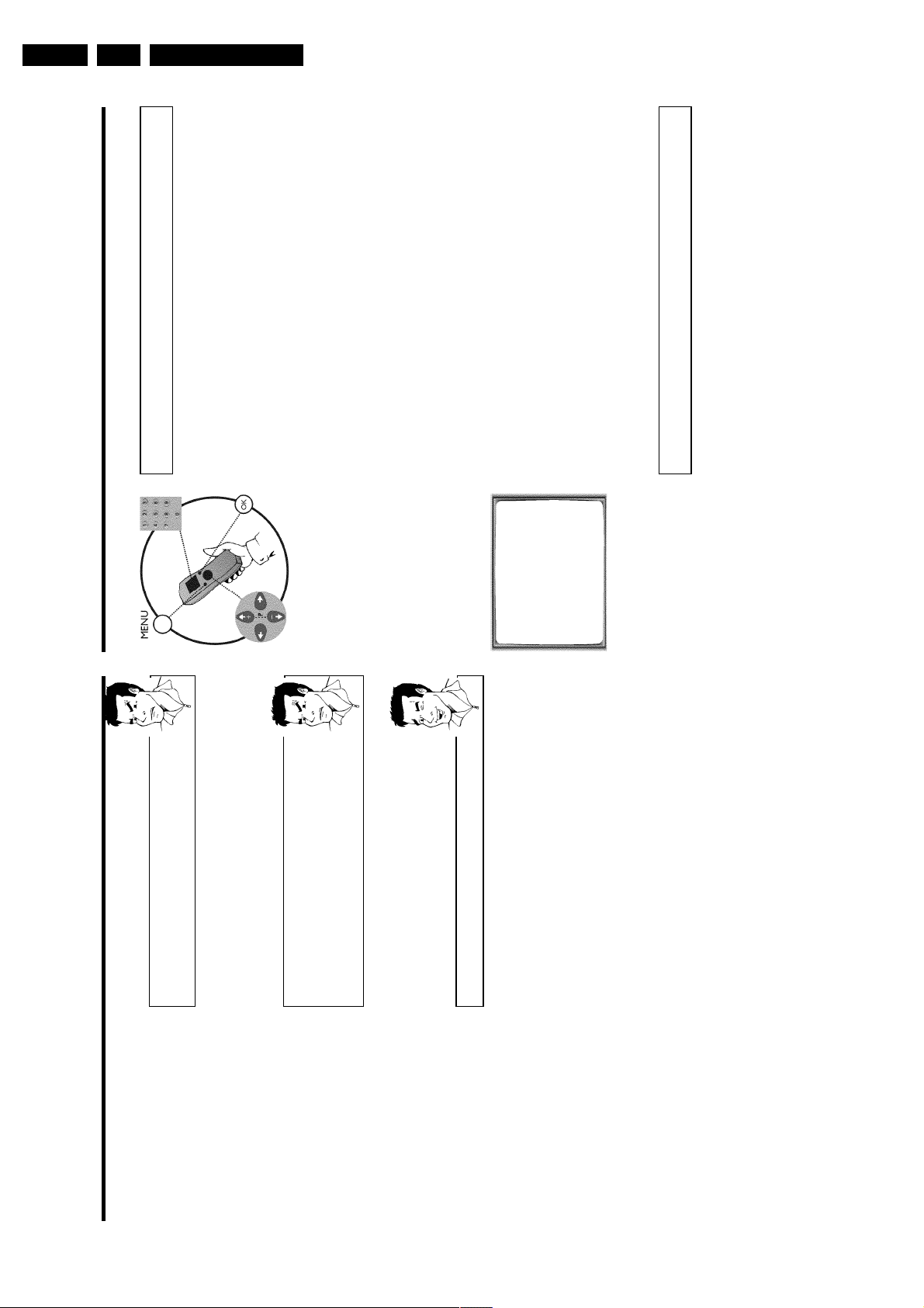
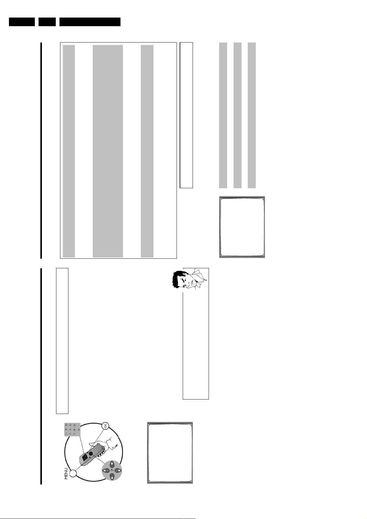
MENU
;Pq
rP=
PLAY G
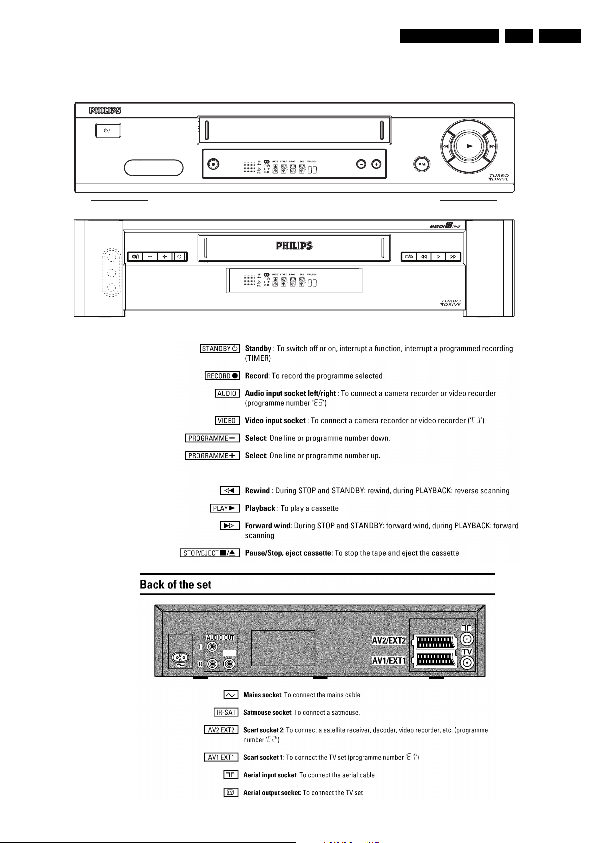
SMART: To adjust the picture setting during playback
Switch off : To switch off set, interruptmenu function, interrupt a programmed recording
(TIMER)
Delete : To delete last entry/Clear programmed recording(TIMER)
Select: To select a function
Child Lock : To switch child lock on/off
TV monitor : To switch between TV reception and VCRplayback
0-9
Number buttons:0-9
TurboTimerAufnahmen programmieren mit der Funktion TurboTimer
TIMER: To make a manual TIMER programming or to alteror clear a programmed TIMER
Menu : To call up or end main menu
OK
Store/Confirm: To store or confirm entry
Q
Select: Cursor left
P
Select: Cursor right
Select: To select a programme number
Select: To select a programme number
Playback : To play a recorded cassette
H
STOP h
I
INDEX E
RECORD n
STILL R
Sq
Sr
TV y
TV m
TV q
TV r
Rewind : During STOP and STANDBY:rewind, during PLAYBACK: reverse scanning
Pause/Stop: To stop the tape, except while a TIMER-recordingis being made
Forward wind: During STOP and STANDBY:forward wind, during PLAYBACK: forward
scanning
Index search: In combination with
H/I
: to search for previous or next recording
on the cassette.
Record: To record the programme selected
Still picture : To stop the tape and show a stillpicture
Additional TV functions
TV volume: TV volume up
TV volume: TV volume down
TV sound off : To switch the sound on or off
Switch off : To switch off the TV
TV Programme number: TV programme number up
TV Programme number: TV programme number down
Page 14
GB 14 VR1203.
Set width 380 mm
Direction for use
VR120
VR402
VR520
VR170
VR570
VR572
VR220
VR420
VR270B
VR270W
VR670B
VR670W
VR620
VR622
VR627
SB140
SB145
SB445
SB645
SB745
+
-
20DV30
45DV30
65DV30
Page 15
SAT
VR870L
VR870C
C
VR720
Set width 435 mm
Direction for use
GB 15VR120 3.
Page 16
GB 16 VR1203.
This
iew
the
the
has
ideo
and
s, it
you
the
and
er.
and
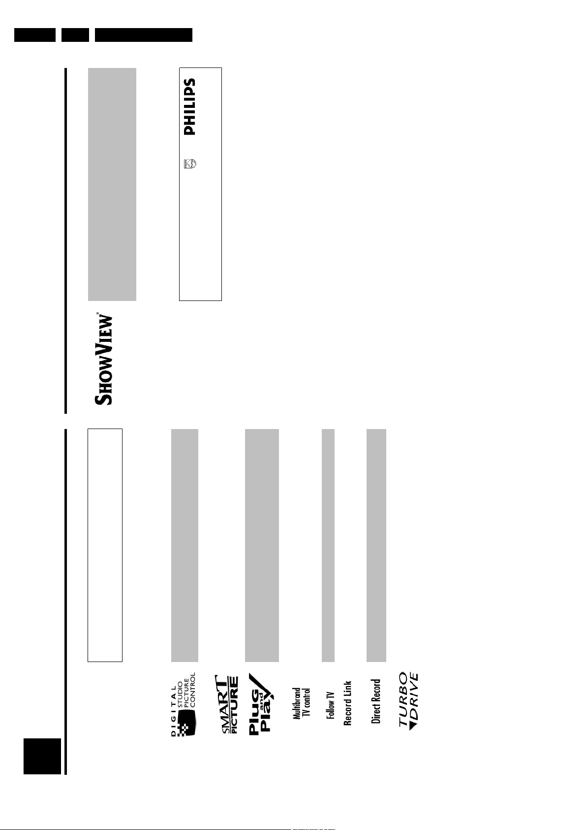
Simple programming system for video recorders. Makes programming as easy as makingatelephone call. Simply enter the number code associated with your television programme.
number is located in your favourite television listings magazine.
ShowView is a registered trademark of Gemstar Development Corporation. The ShowV
system is manufactured under licence from Gemstar Development Corporation.
So that you can identify your machine for service questions or in the event of theft, enter
serial number here. The serial number (PROD.NO.) is printed on the type plate fixed at
back of the device.
Direction for use
MODEL NO. VR720/58
PROD. NO. ..................
Special functions of your new video
recorder
Introduction
1
Your PHILIPS video recorder is not just for recording and playing back VHS cassettes. It also
a whole range of special functions which will make the day-to-day use of your new v
recorder much easier.
Philips has developed a system which produces the best possible playback quality. For old
often-used video cassettes, this system reduces interference. For new or high quality cassette
emphasises the details.
This function allows you to save the playback settings that suit you best. Select your own personalsettings for this type of film you are currently watching.
When you connect your video recorder to your television and plug it into the wall socket,
will be welcomed with a screen menu. All you have to do is follow the instructions in
'intelligent help line' for the next step. Enjoy the automatic TV channel search/save function
the automatic time setting.
You can operate the main functions on your television using your video recorder remote control,even if your television is not a Philips.
This function automatically transfers all the television channel settings onto your video record
Recordings made on your video recorder can be controlled by an external satellite receiver.
Your video recorder can ascertain which channel is currently playing on your television
record from it at the touch of a button.
The precision tape drive from Philips provides short rewind times and automatic tape length
recognition.
Page 17

Direction for use
Connecting the video recorder
Preparing the remote control for
operation
The remote control and its batteries are packed separately in the original video recorder
packaging. You must install the batteries in the remote control before use - described in the
following section.
1 Take the remote control and the enclosed batteries (2 batteries).
2 Open the remote control's battery compartment and place the
batteries in it as shown in the picture and close the battery
compartment.
The remote control is now ready to use. Its range is approximately 5 meters.
Connecting your video recorder to the TV
set
The necessary cable connections must be made before you can record or playback TV
programmes using your video recorder.
We recommend that you use a scart cable to connect your TV set and video recorder.
What is a scart cable?
The scart or Euro AV cable serves as the universal connector for picture,
sound and control signals. With this type of connection, there is practically no
loss of quality during the picture or sound transfer.
When you install your video recorder for the first time, select one of the following options:
'Connecting with a scart cable'
If your TV set has a scart socket and you are using a scart cable.
'Connecting without a scart cable'
If you do not wish to use a scart cable.
The symbols on your video recorder
display
These symbols can light up on your video recorder display:
This is where the current operating mode is shown as a symbol.LPWhen you have switched on the LP (Long Play) function or when you
play a tape that has been recorded in LP (Long Play).
When you have switched on the child lock.
When a satellite recording has been programmed.
DEC
When a decoder has been allocatedto the TV channel (currently
selected programme number on the video recorder) you have currently
selected on the video recorder.
When you play a cassette that has been recorded with hifi sound, or
when a hifi sound is transmitted.
When you are making a recording.kWhen you have programmed a recording or when a programmed
recording is being made.DWhen you are programming daily recordings.WWhen you are programming weekly recordings.
When you have put a cassette in the video recorder.
DATE
When the date of the programmed recording is shown.
START
When the start time of the programmed recording is shown.
PROG.
When the programme number of the programmed recording is shown.
END
When the end time of the programmed recording is shown.
VPS/PDC
Video Programming System / Programme Delivery Control: when a VPS
or PDC code is being transmitted.
Display of programme number of the TV channel / tape position /
channel name / function.
Tape position in seconds.
GB 17VR120 3.
Page 18
GB 18 VR1203.
aMy screen is empty
b Many TV sets are switched to the programme number for the scart socket
by way of a control signal sent through the scart cable.
number, manually change to the corresponding programme number on your
TV set (see your TV's operating instructions).
b If the TV set does not automatically switch to the scart socket programme
Direction for use
set. Insert it into the socket 2 at the back of the video recorder.
back of the video recorder and the other end into the aerial input
socket at the back of the TV set.
4 at the back of the video recorder and the other end into the wall
socket.
Which programme number is used for video recorder operation?
video playback on your TV set (see your TV's operating instructions).
To ensure the stability of the television picture during cassette playback
(prevention of waves or streaks), special programme numbers have been set
aside on the TV for the use of video recorders. This is usually the highest
possible programme number, e.g. '12', '16', '99' or even programme number
'0'. For more information, please see your TV's operating instructions.
CONGRATULATIONS
YOU NOW OWN A NEW
PHILIPS
VIDEO RECORDER
Then, read the paragraph 'Initial installation' in the chapter 'Installing your video recorder'.
CONTINUEpOK
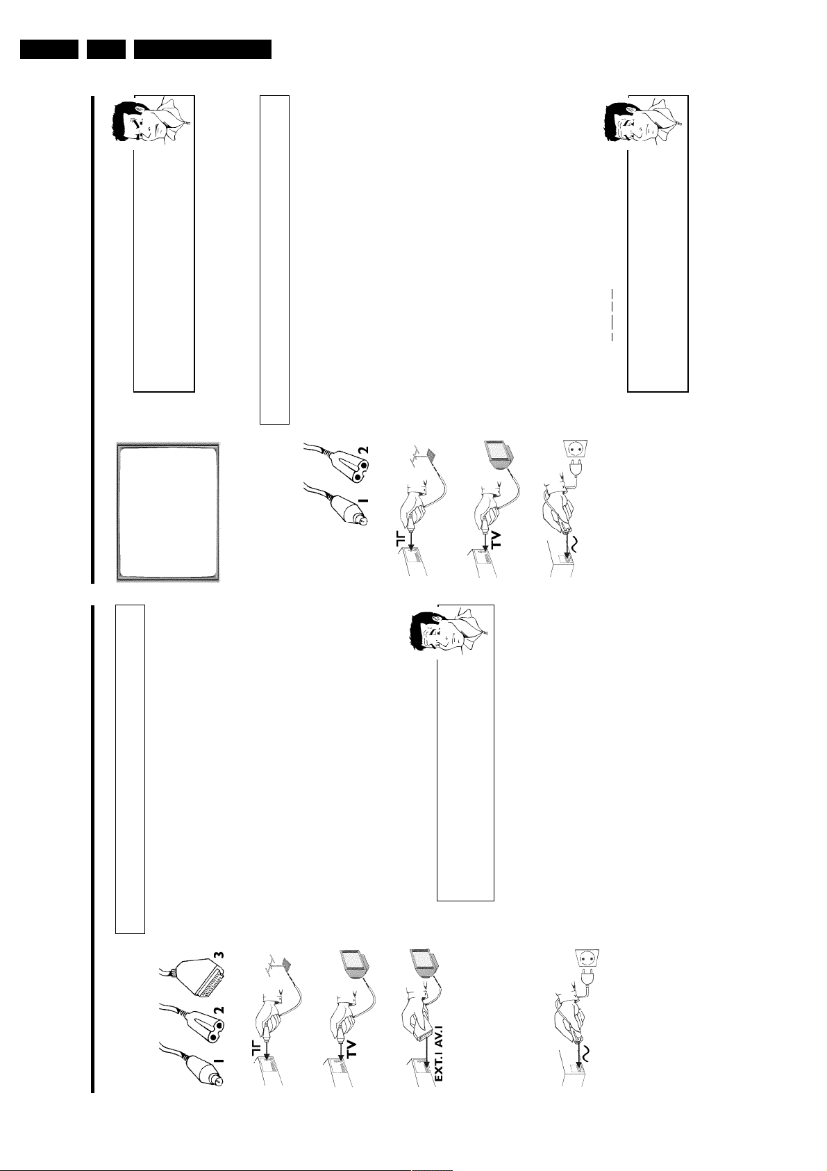
Connecting without a scart cable
Have the following cables ready:
an aerial cable (1, supplied), a mains cable (2, supplied).
1 Switch off your TV set.
2 Remove the aerial cable plug from the aerial input socket of the TV
3 Insert one end of the supplied aerial cable into the socket 3 at the
4 Insert one end of the supplied mains cable into the mains socket
5 Switch on your TV set and select the programme number used for
Connecting with a scart cable
Have the following cables ready:
socket 2 at the back of the video recorder.
an aerial cable (1, supplied), a mains cable (2, supplied), a scart cable (3).
1 Remove the aerial cable plug from your TV set. Insert it into the
socket at the back of the TV set.
back of the video recorder and the other end into the aerial input
2 Insert one end of the supplied aerial cable into the socket 3 at the
3 Plug one end of a scart cable into the scart socket EXT.1 AV 1 at
scart socket on your TV set (see your TV's operating instructions).
the back of the video recorder and the other end into the suitable
My TV set has several scart sockets. Which one should I use?
4 Switch on the TV set.
5 Insert one end of the supplied mains cable into the mains socket
4 at the back of the video recorder and the other end into the wall
socket.
'0', 'AV', you will see the following picture:
switched to the programme number for the scart socket, e.g. 'EXT',
6 If the connection was properly made and your TV was automatically
Select 'TV' as a connection source of this scart socket.
video input.
My TV offers me a selection menu for the scart socket.
Select that scart socket which is suited for the video output as well as for the
Page 19
Direction for use
Installing your video recording
Initial installation
This chapter shows you how to start the initial installation. The video recorder automatically
seeks out and stores all available TV channels.
'Aim' correctly
In the following sections, you require the remote control for the first time.
When using, always aim the front of the remote control at the video recorder
and not at the TV set.
Connecting additional devices
After you have connected additional devices (satellite receiver, etc.) through
the aerial cable, switch them on. The automatic channel search will recognise
them and save them.
1 Confirm the image on the TV screen by pressing the OK button on
the remote control.
2 Select the desired language for the on-screen menu by pressing
P r= or ;qP .
What is an onscreen menu?
The multi-language on-screen menu takes the mystery out of using your new
video recorder. All settings and/or functions are displayed on your TV screen
in the corresponding language.
3 Confirm with OK .
4 Select the country of your residence with P r= or ;qP .
If your country does not appear, select 'OTHERS'.
Confirm with OK .
aThe video recorder does not find any TV channels during the
search
b Select channel 1 on the TV set. Can you see the saved TV channel on the
TV set?
If not, check the cable connection of the aerial (aerial socket), video
recorder, TV set.
b Please have patience.
The video recorder searches the entire frequency range in order to find
and save the largest possible number of TV channels. It is possible that the
TV channels in your country are broadcast in a higher frequency range. As
soon as this range is reached during the search, the video recorder will find
the TV channels.
CLOCK
YEAR è 2001 p
MONTH 01
DATE 01
TIME 20:00
SMART CLOCK ON
________________________________
EXITpMENU STOREpOK
5 When the automatic TV channel search is complete, 'STORED' will
briefly appear on the TV screen.
'YEAR', 'MONTH', 'DATE', 'TIME' will appear on the TV screen.
6 Check the year in line 'YEAR'. If required, please change the year with
the number buttons 0-9 on the remote control.
6 Select this programme number and manually start the TV's channel
search as if you wanted to save a new TV channel until the 'test
image' appears.
CONGRATULATIONS
YOU NOW OWN A NEW
PHILIPS
VIDEO RECORDER
CONTINUEpOK
aI do not see a 'test screen'
b Check the cable connections.
b The video recorder 'transmits' on the 591MHz frequency (channel 36)
Repeat the channel search on your TV set.
7 Save this programme number setting on your TV set for video
recorder operation.
Programme number for video recorder operation
You have now saved a programme number for use by your video recorder as
you would a regular TV channel. This programme number must now be used
in future for video recorder playback ('video recorder' TV channel).
You can find more details in chapter 'Initial Installation'.
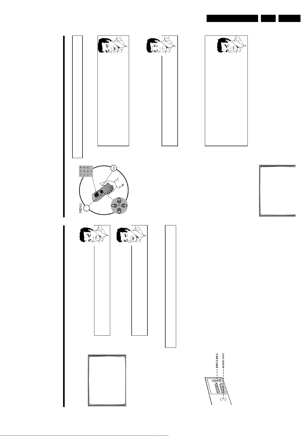
Connecting additional devices
You can connect additional devices such as decoders, satellite receivers, camcorders, etc. to the
socket EXT.2 AV 2 .
Two audio sockets AUDO OUT L R are located on the back of the video recorder (audio
signal output left/right). These can be used to connect stereo systems.
GB 19VR120 3.
Page 20
GB 20 VR1203.
the
and
ially
der
the
Direction for use
on the screen to select 'OFF' (Decoder switched off).
P
How can I switch off the decoder?
SEARCH' and confirm with OK .
Use the button
the video recorder.
The main menu will appear.
OK .
want to use for the TV channel, e.g. 'P01'.
4 Use the buttons ;qP or P r= to select the line 'MANUAL
5 Use the buttons P r= or ;qP to select the line 'DECODER'.
MANUAL SEARCH
6 Use the buttons Q or P to select 'ON' (Decoder switched on).
PROGRAMME NUMBER è P01 p
7 Confirm with OK .
8 End with the button MENU .
The decoder has now been allocated to this TV channel.
If this TV channel is chosen, the symbol 'DEC' will appear in the video recorder display.
Manual TV channel search
In some cases it could occur that all of the TV channels were not found and saved during
initial installation. In this case, the missing or coded TV channels must be searched for
stored manually.
1 Switch on the TV set. If required, select the programme number for
2 Press MENU on the remote control.
3 Select line 'MANUAL SEARCH' using P r= or ;qP and confirm with
5 Using Q or P , select the desired programme number that you
4 Select line 'PROGRAMME NUMBER' using P r= or ;qP .
6 In line 'S-CHANNEL', select the desired display using P .
BBC1
S-CHANNEL NO
CHANNEL NUMBER 21
DECODER OFF
NICAM ON
TV SYSTEM AUTO
________________________________
EXITpMENU STOREpOK
MANUAL SEARCH
PROGRAMME NUMBER è P01 p
S-CHANNEL NO
CHANNEL NUMBER 21
DECODER OFF
NICAM ON
TV SYSTEM AUTO
________________________________
EXITpMENU STOREpOK
no sound at all, it is possible that the incorrect TV system was saved for
this TV channel. In the chapter 'Manual TV channel search' you will find the
information on how to change the TV system.
aSound disruptions can occur on several TV channels
Satellite receiver
If you are connecting a satellite receiver, please read the section 'Using the
satellite receiver'.
Decoder
If you are connecting a decoder, you must install it as described in the next
briefly flash in the video recorder display.
correct.
8 Check if the displayed settings for 'MONTH', 'DATE' and 'TIME' are
7 Select the next line with ;qP or P r= .
9 When all information is correct, save by pressing OK .'STORED' will
The initial installation is now complete.
section.
b If sound disruptions should occur for several saved TV channels or there is
Decoder allocation
Some TV channels transmit encoded TV signals which can only be viewed with a commerc
purchased or hired decoder without disturbances. You can connect such a deco
(descrambler) to this video recorder. The following function will automatically activate
connected decoder for the desired TV channel.
video recorder operation.
1 Switch the TV on. If applicable, select the programme number for the
buttons 0-9 on the remote control to select the TV channel which
2 Use the buttons ;qP , P r= on the video recorder or the number
appear.
you would like to allocate the decoder to.
3 Press the button MENU on the remote control. The main menu will
Page 21
Direction for use
Using the satellite receiver
TV channels from a satellite receiver (connected to the scart socket EXT.2 AV 2 ) are received
on the video recorder on programme number 'E2'.
To do this, select programme number 'E1' with 0 on the remote control and then select
programme number 'E2' with P r= .
You should select the TV channels to be received by the satellite receiver directly on the
receiver itself.
Sorting TV channels automatically
(Follow TV)
When the automatic channel search function is activated, the TV channels are saved in a specific
order. This may vary from the order of TV channels on the TV set.
This function changes the order of TV channels saved in the video recorder to match that of the
TV set.
This only works if the video recorder (socket EXT.1 AV 1 ) and the TV set are connected
with a scart cable.
1 Switch on the TV set. If required, select the programme number for
the video recorder.
2 Press the MENU button on the remote control. The main menu will
appear.
MENU
CLOCK
AUTO TUNING
MANUAL SEARCH
FOLLOW TV
TV CHANNEL ALLOC.
RECORD SPEED
AUTO STANDBY
VIDEOSYSTEM
LANGUAGE
SPECIAL SETTINGS
________________________________
…EXITpMENU OK
†HOTLINEpCL
3 Select line 'FOLLOW TV' using P r= or ;qP and confirm with
OK .
4 Press the OK button. 'TV01' will appear in the video recorder display.
TV01
5 Select programme number '1' on the TV set.
What is hidden behind the settings?
'NO': Display/Entry of channels
'YES': Display/Entry of special channels
What is a special channel?
TV channels are transmitted in certain pre-defined frequency ranges. These
ranges are divided into channels. A specific frequency/channel is assigned to
each TV station. Certain frequency ranges are specified as special channels
(hyperband channels).
7 In line 'CHANNEL NUMBER', enter the channel of the desired TV
station using the number buttons 0-9 .
aI don't know the channels for my TV stations
b In this case, press
P
in line 'CHANNEL NUMBER' to start the automatic
channel search. A changing channel number will appear on the TV screen.
Continue the automatic search until you have found the desired TV
channel.
What is NICAM?
NICAM is a digital sound transmission system. Using NICAM, you can
transmit either 1 stereo channel or 2 separate mono channels. However, if
you experience poor reception resulting in sound disruptions, you can turn off
NICAM.
In line 'NICAM', select 'OFF' using
Q
or
P
.
How can I change the TV transmission system of the TV channel?
In line 'TV SYSTEM', select the corresponding TV system using
Q
or
P
until the picture/sound disruptions are minimised.
8 Save the TV channel with OK .'STORED' will briefly appear on the
TV screen.
9 To search for other TV channels, begin again at step
3
.
0 To end, press MENU .
GB 21VR120 3.
Page 22
GB 22 VR1203.
nnel
ideo
nnel
with
rto
Direction for use
Automatic TV channel search
During installation, all available TV channels are searched for and saved. If the cha
, please
EXT.2 AV 2
assignments of your cable or satellite TV provider change or if you are reinstalling the v
recorder, e.g. after moving house, you can start this procedure again. This will replace theTVchannels already saved with the new ones.
1 Switch on the TV set. If required, select the programme number for
the video recorder.
2 Press the MENU button on the remote control. The main menu will
appear.
If your country doesn't appear, select 'OTHERS'.
4 Press OK .
3 Select line 'AUTO TUNING' using P r= or ;qP .
6 Press OK .
5 Select the country of your residence with ;qP or P r= .
7 The automatic TV channel search starts. This allows the video
AUTO TUNING
.
CLEAR (CL)
recorder to save all available TV channels. This procedure may take
several minutes.
8 When the TV channel search is complete, 'STORED' will briefly appear
SEARCHING
00 TV CHANNELS FOUND
on the TV screen.
9 To end, press MENU .
ƒƒƒƒƒƒƒ__________________
You can read about how to search for a TV channel manually in the section 'Manual TV cha
PLEASE WAIT...
search'.
Monitor function
MONITOR . But this only works when you use a scart cable to connect the video recorde
You can switch back and forth between the TV picture and video recorder picture
your TV set and your TV set responds to this switch-over.
until you have assigned a programme number
9
to
7
receiving a video signal from the TV set.
for video signals.
disconnect these devices. Because of other connected devices, the TV set
could switch to the programme number of the scart socket.
aI cannot switch my TV set to programme number '1'
b If you have connected additional devices to socket
6 Confirm with OK on the video recorder remote control. The video
recorder compares the TV channels on the TV set and the video
recorder.
If the video recorder finds the same TV channel as on the TV set,
then it stores it at 'P01'.
a'NOTV' will appear in the display. The video recorder is not
b Check the plug on the scart cable.
b Check your TV's operating instructions to see which scart socket is used
Please read the section 'Sorting TV channels manually'.
b If this does not help, it's not possible to use this function.
7 Wait until the next number, e.g. 'TV02' appears in the display.
Deleting sorting
You can delete an incorrect TV channel sorting by pressing
to all TV channels.
8 Select the next programme number on the TV set, e.g. '2'.
9 Confirm with OK on the video recorder remote control.
0 Repeat steps
A To end, press MENU .
Page 23

Direction for use
aThe main menu will appear on the screen
b After you have confirmed the last channel that can be sorted, you will
automatically return to the main menu since no more TV channels can be
assigned.
0 To assign other TV channels to a programme number, repeat steps
7
to
9
.
A Confirm the assignment of the TV channel with MENU .
B To exit the main menu, press MENU .
Setting onscreen menu language
You have the option of setting one of the displayed languages for the on-screen menu (OSD).
However, the video recorder display will only display English text regardless of this setting.
1 Switch on the TV set. If required, select the programme number for
the video recorder.
2 Press MENU on the remote control. The main menu will appear.
MENU
CLOCK
AUTO TUNING
MANUAL SEARCH
FOLLOW TV
TV CHANNEL ALLOC.
RECORD SPEED
AUTO STANDBY
VIDEOSYSTEM
LANGUAGE
SPECIAL SETTINGS
________________________________
…EXITpMENU OK
†HOTLINEpCL
3 Select line 'LANGUAGE' and confirm with OK .
4 Select the desired language with P r= or ;qP and confirm with
OK .
'STORED' will appear briefly on the screen.
5 To end, press MENU .
Sorting and clearing TV channels manually
After you have performed the automatic channel search you may not agree with the sequence in
which the individual TV channels have been allocated to the programme positions (programme
numbers) of the video recorder. You can use this function to individually sort the TV channels
already saved or to delete unwanted TV channels or those with poor reception.
1 Switch on the TV set. If required, select the programme number for
the video recorder.
2 Press MENU on the remote control. The main menu will appear.
3 Select line 'TV CHANNEL ALLOC.' using P r= or ;qP .
4 Confirm with OK .
TV CHANNEL ALLOC.
ALLOCATE ON P01
TV CHANNEL è CNN p
________________________________
ALLOCATEpOK EXITpMENU
5 Using Q or P , select the saved TV channel that you want to
assign to the programme number 'P01'.
6 Confirm with OK . The following message will briefly appear on the
TV screen: 'ALLOCATED ON P01'.
7 Then the sorting for the next highest programme number will appear
on the screen, e.g. 'ALLOCATE ON P02'.
8 Using Q or P , select the saved TV channel that you want to
assign to this programme number, e.g. 'P02'.
Deleting TV channels
Using
CLEAR (CL)
you can delete unwanted TV channels or those with
poor reception.
9 Confirm with OK . The following message will briefly appear on the
TV screen: 'STORED'.
GB 23VR120 3.
Page 24
GB 24 VR1203.
s
o
enu.
ber
)
0-9 or by putting in a cassette.
You can switch on the video recorder with the STANDBY/ON m button, the number button
If the video recorder is not used for several minutes, it switches itself off automatically. Thisfunction can be deactivated (e.g. if you want to use the video recorder as a TV receiver). For moreinformation, please read the section 'Automatic switch-off' in chapter 'Additional functions'.
If you have switched the video recorder off with STANDBY/ON m , the time will show in thedisplay, e.g. '18:00'.
If the clock has not been set, '--:--' will appear.
When the video recorder is switched off and the time isn't shown in the video recorder display,the clock display may be switched off. You will find more information in the chapter 'Additionalfunctions' section 'Switch off the clock display'.
Direction for use
The video recorder should always be connected to the mains so as not to affect the use of the TVor programmed recordings.
Your video recorder uses less than 4W (with clock display switched off).
Channel information remains saved for up to 1 year, the time and timer information is saved for upto 3 hours.
The video recorder and the remote control have the option of an 'Emergency exit'. You can usethe STANDBY/ON m button to interrupt any function or step during use.
You can operate your device without worry. There is no risk whatsoever of damaging the vide
recorder by performing user steps incorrectly.
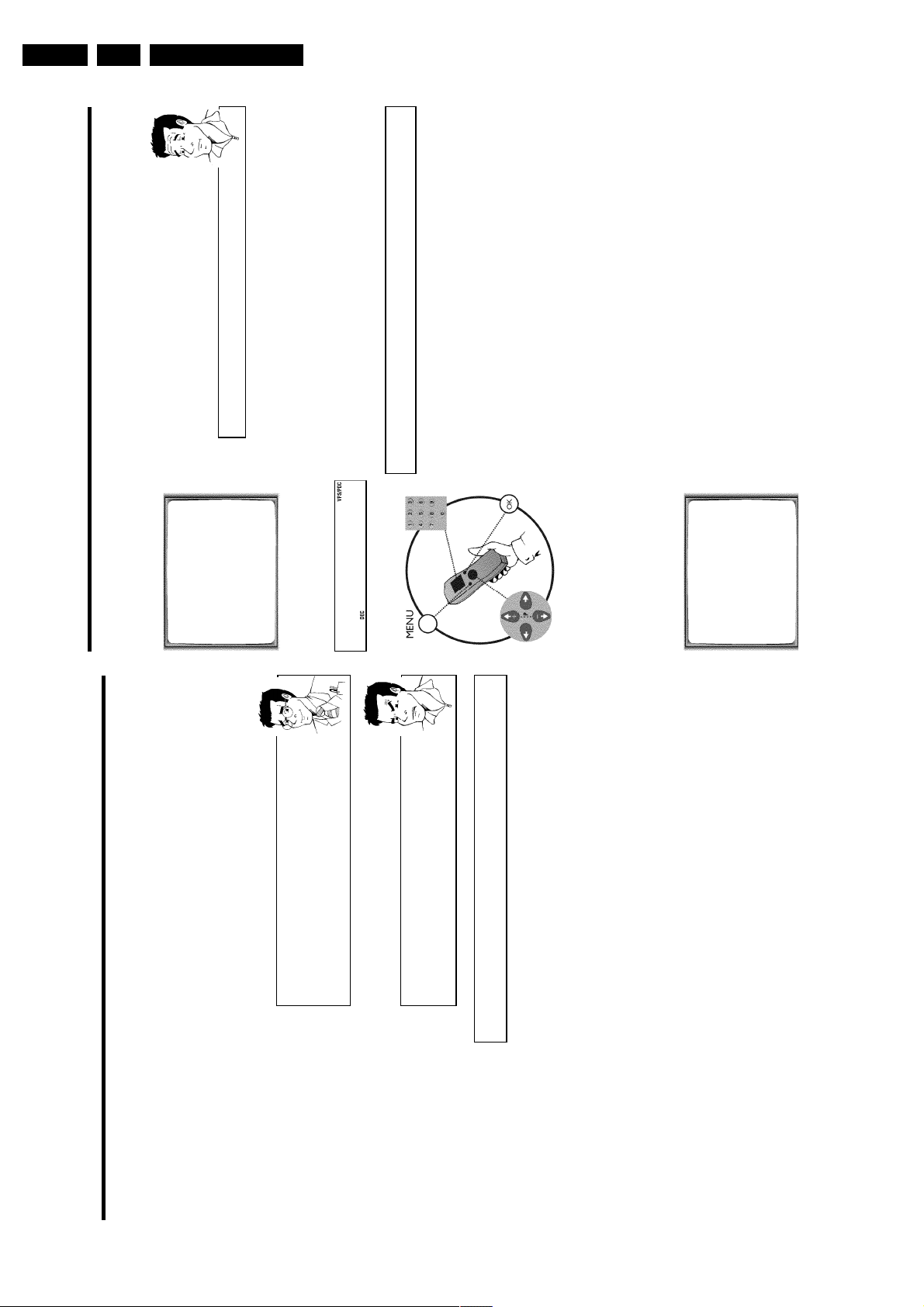
Navigation in the screen menu
You can check/change many functions and settings of your video recorder via the screen m
The individual functions are selected as follows:
Call up the menu: with MENU .
To select: with P r= or ;qP .
To cancel: with STANDBY/ON m .
To enter or change your selection: with the number buttons 0-9 or with Q or P .
To end: with MENU .
To save or confirm: with OK .
Important notes for operation
Switching on
Setting the time and date
If the display shows an incorrect time or '--:--', the time and date must be reset manually.
If a TV channel which transmits TXT/PDC (teletext/PDC) is stored under programme num
Automatic switchoff
1 Switch on the TV set. If required, select the programme number for
'P01', time/date will automatically be taken from the TXT/PDC information. (SMART CLOCK
Time in the display
the video recorder.
2 Press MENU on the remote control. The main menu will appear.
Energy consumption
Power outage/no
power
the number buttons 0-9 on the remote control.
3 Select line 'CLOCK' using P r= or ;qP and confirm with OK .
4 Check the year in line 'YEAR'. If required, please change the year with
Emergency exit
5 Select the next line with ;qP or P r= .
6 Check 'MONTH', 'DATE' and 'TIME' in the same way.
aTime/date is displayed incorrectly despite manual setting
'P01' and automatically corrected.
b With Smart Clock, time/date is transferred from the TV channel saved on
or
Q
Switch off Smart Clock. In line 'SMART CLOCK', select 'OFF' using
CLOCK
AUTO TUNING
MANUAL SEARCH
FOLLOW TV
TV CHANNEL ALLOC.
RECORD SPEED
AUTO STANDBY
VIDEOSYSTEM
LANGUAGE
MENU
.
P
You can switch on 'SMART CLOCK' again when you select 'ON'.
'STORED' will appear briefly on the screen.
7 Check the displayed settings and confirm with OK .
SPECIAL SETTINGS
________________________________
…EXITpMENU OK
†HOTLINEpCL
8 To end, press MENU .
CLOCK
YEAR è 2001 p
MONTH 01
DATE 01
TIME 20:00
SMART CLOCK ON
________________________________
EXITpMENU STOREpOK
Page 25
Direction for use
Why must I note the cassette number?
When searching for available recordings, you will need to insert the
corresponding cassettes (cassette numbers).
How many cassettes can I save in the Tape List?
You can store up to 9 cassettes. You can store a maximum number of 50
titles in the Tape Manager.
Editing recording titles
In the Tape List, all recordings longer than 10 minutes are displayed with cassette number,
recording title and length of recording. The TV channel, time and date are saved as a title. The
title of this recording can only be changed after the recording has been completed.
To do this, the corresponding cassette does not have to be in the video recorder. In the
following, you will read how to customise the titles to your wishes.
1 Press TAPE LIST on the remote control. An overview of all saved
titles/cassettes from the Tape List appears on the screen.
aI can see the message 'TAPE LIST- MEMORY EMPTY'
b There are no recordings saved in the Tape List. Therefore, it is not
possible to add or change a title.
2 Using ;qP or P r= select the title to be edited and confirm with
P .
3 Using P or Q select the position where the letter/number/symbol
is to be changed or re-entered.
4 Change the desired symbol using ;qP or P r= .
Deleting symbols
To delete a symbol of a recording title, press
CLEAR (CL)
at the
corresponding symbol position.
5 Repeat step
3
and step
4
until you have made the desired changes.
6 Save the new title with OK .
7 If you want to change more titles, repeat step
3
through step
7
.
8 To end, press TAPE LIST .
Tape List
General information
The 'Tape List is an integrated database in the video recorder that remembers all recordings
made by this video recorder. The Tape List helps you keep track of which film is on which
cassette. The 'Tape List' also gives you quick and easy access to recordings.
And: If desired, the video recorder will rewind to the beginning of the selected recording and
automatically start playback.
Can I add cassettes that already have recordings on them to the
Tape List?
Yes. Tape List can manage a maximum of 9 cassettes. However, there must be
recordings on the cassettes in order to copy them to the Tape List database.
Adding a cassette to the Tape List
You can add any cassette to the 'Tape List'. Please note that the process for adding cassettes
that already have recordings on them lasts longer than with new (blank) cassettes.
1 Switch on the TV set. If required, select the programme number for
the video recorder.
2 Label the cassette to be inserted with a number from 1 to 9.
3 Insert the cassette into the video recorder.
4 'TAPE' will appear in the display.
5 Enter the cassette number using the 0-9 number buttons on the
remote control.
The video recorder will briefly check the cassette inserted.
'CHECKING CASSETTE' appears on the TV screen.
If the cassette is new (blank), no information will appear on the
screen.
aI see a cassette number and an overview of all recordings on this
cassette
b You have selected a number which has already been included in the Tape
Manager and contains a recording.
On the screen after 'CHECKING CASSETTE' I see the message ''
There are already recordings on the cassette. This cassette is searched for
recordings and added to the Tape List.
GB 25VR120 3.
Page 26
GB 26 VR1203.
rate
er.
ape
and
What does VHS mean?
'Video Home System' (VHS) has become the world-wide standard for the
playback and recording of amateur video cassettes. This popular standard
continues to be improved. Super VHS (S-VHS) provides a sharper picture and
Direction for use
less noise. Digital VHS (D-VHS) only works with digital picture and sound
signals. Your video recorder can only record and play standard VHS cassettes.
The cassette is inserted automatically. ' v ' will appear on the display.
aI see 'TAPE' in the display
b The video recorder is waiting for you to enter a cassette number from the
'Tape List'. You can find more information on the Tape List in the chapter
'Tape List'.
This will, for example, appear in the display:
aPicture/ sound quality is poor
possible to completely filter out picture and sound interference. This is not
a fault in your machine.
Please read the section 'Selecting the picture settings (SMART PICTURE)',
or the chapter 'Eliminating picture interference'.
picture/sound interference occurs, attempt to fix the problem by manually
switching the TV system. In that case, turn to chapter 'Additional functions'
b When playing rental videos or older, poorer quality cassettes, it may not be
section 'Switching the video (color) system'.
b During playback the automatic TV system will switch-over automatically. If
STOP/EJECT ? on the video recorder.
recorder when the video recorder stops the playback (STOP).
To eject a cassette, you can also use EJECT J on the remote
control.
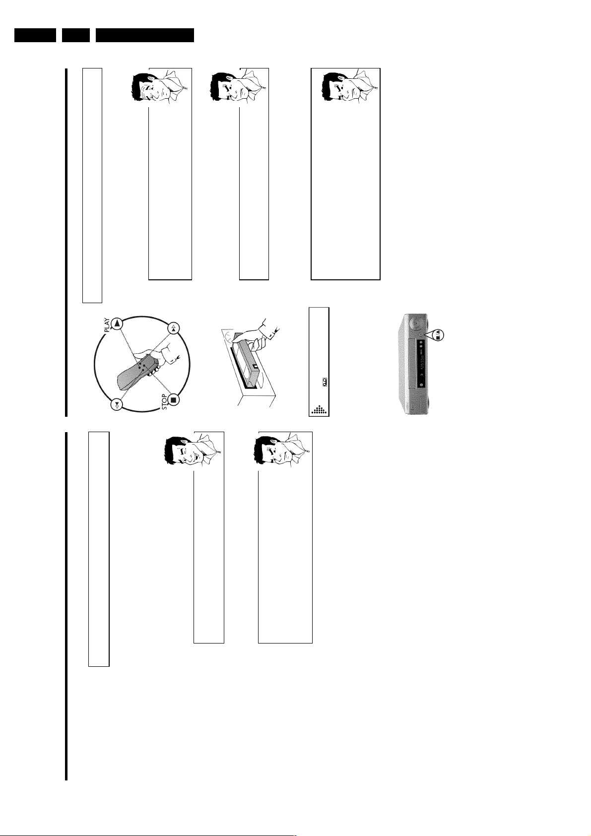
Playing cassettes
Playback
You can use this video recorder to play back recorded VHS video cassettes. You can ope
the video recorder using the remote control or the buttons on the front of the video record
1 Put a cassette into the cassette slot.
2 Press the Play button PLAY G to view the tape.
.
MENU
02
0:00:
3 To stop the playback, press STOP h on the remote control or
4 To eject the cassette, press STOP/EJECT ? on the video
Searching for a title in the Tape List
This function can be used to quickly and easily find and play back a recording saved in the T
List. The video recorder automatically rewinds to the beginning of the selected recording
automatically starts playback.
1 Press TAPE LIST on the remote control.
2 An overview of all recordings saved in Tape List appears on the
screen.
What do the displays on the screen mean?
'CASS.' = Cassette number
'TITLE' = Title (TV channel, time, date)
'LENGTH' = Length of the recording
displayed cassette number. Please insert the corresponding cassette. After a
brief check, the video recorder will rewind to the beginning of the selected
recording and start playback.
aI see the message 'INSERT CASSETTE X' on the screen.
b The selected recording is located on the Tape List cassette with the
3 Select the title that you want to play back with P r= or ;qP .
aI want to cancel the search
b If you want to cancel the search, press
selected recording and automatically starts playback.
4 Confirm with OK . The video recorder winds to the start of the
Page 27
Direction for use
aThe counter does not move
b This occurs when there are no recordings on a portion of a tape.
Therefore, the video recorder cannot receive any information from the
tape. This is not a fault in your machine.
aThe display/the screen shows '-0:01:20'
b If you rewind a cassette from the tape position '0:00:00', the counter will
show for instance, '-0:01:20' (the cassette will be rewound to 1 minute
and 20 seconds before '0:00:00').
a':' is displayed in the 'REMAIN' counter
b This counter will automatically recognise the length of the tape. In addition,
when you put in a cassette the video recorder must first calculate the time
played. Therefore, '-:--' appears first and only after the tape has been
running for a few seconds will the correct playing time be shown.
Searching for a tape position with picture
(scanning)
0:30:
21
1 While a cassette is playing, press H (reverse) or I (forward) one
or more times. This will, for example, appear in the display:
2 To stop at a certain place on the tape, press PLAY G .
Decreased picture quality
Scanning interferes with the picture quality. The sound is switched off. This is
not a fault in your machine.
Still picture / slow motion
0:00:
02
1 During playback, press STILL R to stop the tape and display a still
picture. This will, for example, appear in the display:
2 Each time you press STILL R , the picture will advance one frame.
3 When you hold down the STILL R button, the tape will be played
in slow motion.
4 When you press I several times, you have a choice of several
playback speeds for slow motion.
5 To continue playback, press PLAY G .
Automatic switchoff of special functions
Many functions (e.g. pause, still picture, search) switch themselves off
automatically after a short time in order to protect the cassette and to save
energy.
Do I need to change the playback speed when playing back LP
recordings?
For playback, the correct recording speed 'SP' will automatically be selected.
For more information, please read the section 'Selecting the recording speed
(SP/LP)' in the chapter 'Manual recording'.
Playing back NTSC cassettes
Cassettes that have been recorded in the NTSC standard (for example, American cassettes) can
be played back using this video recorder. However, this only works on PAL-television sets which
are suitable for a picture frequency of 60Hz.
When you play an NTSC cassette '60HZ' will appear on the display.
Some special features (for example, still picture) are not possible while you are playing an NTSC
cassette.
Displaying current tape position
The display shows the tape position in hours, minutes and seconds. In addition, by pressing
OK you can show the present tape position on the TV screen.
The following information is displayed on the screen:
e.g.: 0:02:45 Shows the tape position in hours, minutes and seconds.
Moving/blinking arrow: This indicates the current tape position. The arrow moves in a line from
left (tape start) to right (tape end).
'REMAIN 0:06': will show the actual amount of playing/recording time left on the tape in hours
and minutes.
When you play an NTSC cassette, the video recorder will not show 'REMAIN 0:06'.
How can I set the counter to '0:00:00'?
You can set the counter to '0:00:00' using
CLEAR (CL)
.
When you put a cassette in the machine, the counter will automatically reset
to 0:00:00'.
GB 27VR120 3.
Page 28
GB 28 VR1203.
, for
ater
Automatic search for a blank space on the
tape
You can search for space on the tape (at least 1 minute of blank tape) for a new recording
example, after an existing recording on the tape.
appear in the display:
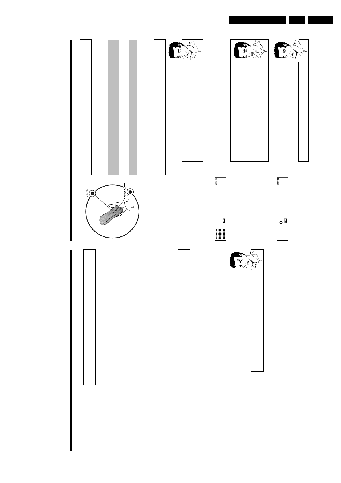
1 Press INDEX E . Then press STOP h . This will, for example,
Direction for use
inserted.
aThe cassette is ejected
b The video recorder was unable to find any blank space on the tape
it automatically switches to pause.
2 As soon as the video recorder finds the corresponding tape position,
Selecting picture settings (SMART
PICTURE)
Using SMART * , you can display and set many stored picture settings for playback.
What types of picture settings are available to me?
'NATURAL': Natural picture (standard setting)
'DISTINCT': Emphasises details (quick movements, sports)
'SOFT': Suppression of interference (when using rental cassettes)
'SHARP': Increase in sharpness (e.g. for animated films)
picture setting.
1 During playback, press SMART * . This will show the current
Press the SMART * button several times to select the
corresponding picture setting.
the selected picture setting will be saved.
2 If the SMART * button is not been pressed after a few seconds,
3 These picture settings will not change until you eject the cassette.
00
0:00:
Searching for tape position without
picture (forward wind and rewind)
in the display:
2 Press H (reverse) or I (forward). This will, for example, appear
3 To stop at a certain place on the tape, press STOP h .
1 Stop the tape with STOP h .
Instant View
With this function you can switch to picture search during wind and rewind.
1 If you hold H (rewind) or I (wind) during wind or rewind, you
will switch to picture search.
2 As soon as you release the button, the video recorder will
automatically switch back to rewind or wind.
Automatic search for a tape position
(index search)
Every time a tape is recorded an index marking is written on the tape. This marking canbecompared with a bookmark. These marked positions can be found again quickly and easily l
by pressing a button.
1 To search for the previous marking, press INDEX E and then H .
21
0:30:
example, appear in the display for the next marking.
2 For the next marking, press INDEX E and then I . This will, for
switches to playback.
3 As soon as the video recorder finds this marking, it automatically
02
0:30:
Page 29
Direction for use
Manual recording
General information
Use 'Manual Recording' to make a spontaneous recording (for example, a programme currently
being shown).
If you want to start and stop a recording manually, read the section 'Recording without
automatic switchoff'.
If you want to start a recording manually but have it stopped automatically, read the section
'Recording with automatic switchoff'. (e.g. not to record to the end of the tape)
Read the section 'Direct record' if you want to record a programme currently being shown.
Read the section 'Automatic recording from a satellite receiver', if you want a recording to
be controlled automaticallyby a satellite receiver.
Recording without automatic switchoff
1 Insert a cassette.
Using 'Tape List'
To save a recording in the 'Tape List' or to use a 'Tape List' cassette, enter
the cassette number using the number buttons
0-9
on the remote control.
The cassette is being checked. You can find more information on the 'Tape
List' in the chapter 'Tape List'.
BBC1
2 Use ;qP or P r= to select the programme number you want to
record, for example, 'P01'. This will appear on the display:
Station name
If a TV station transmits a station name, it will be shown in the display.
Programme numbers 'E1''E2'
This programme number is provided for recording from external sources (via
the scart socket
EXT.1 AV 1
,
EXT.2 AV 2
).
Programme number 'E3'
This programme number is used for recording from the audio and video front
sockets.
BBC1
3 To start recording, press RECORD/OTR n on the remote control
or RECORD n on the video recorder. This will, for example, appear
in the display:
Displaying tape position
Using
OK
you can show the tape position in the display.
Eliminating picture interference
Optimising tracking
This video recorder has an automatic tracking function. In order for the video heads to optimally
read the video track of the newly inserted video cassette, the tape speed is slightly corrected
automatically.
In some cases however, interference will still occur.
The following section will explain how to manually adjust the tracking settings.
1 While a cassette is playing, hold ;qP until 'TRAC' (TRACking)
appears in the display.
2 Hold down the buttons ;qP or P r= until the playback quality is
at its best.
3 Wait a few seconds, until 'TRAC' disappears from the display.
These selected picture settings will not change until you eject the cassette.
Optimising still picture
If the still picture vibrates vertically, you can improve the still picture as follows:
1 During still picture, hold ;qP or P r= until the picture quality is at
its best.
'JITT' will appear in the display.
2 When you release the button, 'JITT' will disappear.
The video recorder will store these settings automatically.
aI cannot reach optimal quality for the still picture
b Interference which cannot be alleviated by this function can occur in
cassettes of poor quality or camcorder cassettes .
GB 29VR120 3.
Page 30
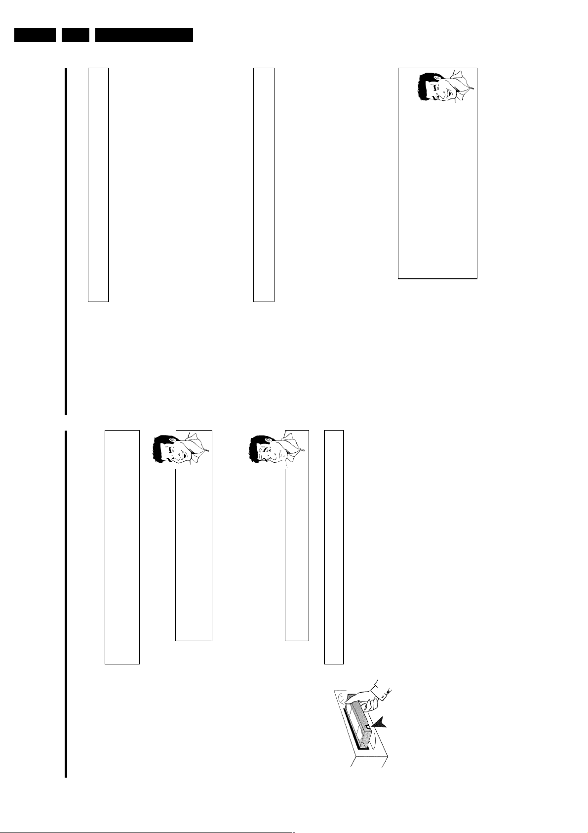
GB 30 VR1203.
hort
ker.
ple,
the
tape
the new recording.
Direction for use
remote control.
new recording is to go. 9 ' will appear on the display.
the video recorder.
recorded on a 4 hour cassette (E240) with a somewhat reduced picture
quality.
'AUTO': AUTOmatic Long Play. If there is not enough space on the tape to
record a programmed recording in standard speed, the recording will
automatically be made in 'LP' (Longplay). Otherwise, the recording speed will
quality.
'LP': LongPlay (half recording speed, double recording time). 8 hours can be
'SP': StandardPlay (normal recording speed) offers the usual first-class picture
OK .
'SP'/'LP' AUTO'
be 'SP' (Standardplay).
Lining up recordings (assemble cut)
Selecting the recording speed (SP or LP)
1 Find the tape position of the old recording where you want to insert
2 Look at the last minute of the old recording (playback).
When you add a further recording to a cassette, which already has a recording on it, a s
blank (flicker) can appear between the old and the new recording or the picture itself can flic
To help reduce these from occurring, proceed as follows:
3 Press STOP h on the remote control at the tape position where the
on the remote control.
0-9
5 Stop recording with STOP h .
4 Now start recording as usual by pressing RECORD/OTR n on the
You can reduce the recording speed by half. This makes it possible to record, for exam
eight-hours instead of four-hours on an 'E240' (four-hour) cassette.
For playback, the correct recording speed will automatically be selected.
while the display shows the
CLEAR (CL)
1 Switch on the TV set. If required, select the programme number for
3 Select line 'RECORD SPEED' using P r= or ;qP and confirm with
2 Press MENU on the remote control. The main menu will appear.
4 Select the required recording speed with Q or P .
Using 'Tape List'
To save a recording in the 'Tape List' or to use a 'Tape List' cassette, enter
the cassette number using the number buttons
The cassette is being checked. You can find more information on the 'Tape
List' in the chapter 'Tape List'.
record.
Recording with automatic switchoff (OTR
4 Stop recording with STOP h .
OneTouchRecording)
1 Insert a cassette.
2 Use ;qP or P r= to select the programme number you want to
3 Press RECORD/OTR n on the remote control.
How can I clear the recording time just setted?
To delete an entry, press
the recording time.
4 Each time you press RECORD/OTR n you will add 30 minutes to
recording time.
Preventing accidental erasing of cassettes
All cassettes (except for rental and store cassettes) have a security tab on the back of
cassette (see arrow).
To prevent recording over important recordings (erasing), you can remove this security taborslide it to the left.
If you later decide to record on a protected cassette, simply cover the hole with adhesive
or slide the tab to the right.
Page 31

Direction for use
The video recorder is now ready to record. The beginning and end of the recording is
controlled via scart socket EXT.2 AV 2 .
When this function is switched on, ' x ' will appear on the video recorder display.
'Direct Record'
Can you record the right TV channel in seconds when the video recorder is switched off? No
problem. If recording is started manually, the switchedoff video recorder uses the current TV
channel setted on the TV set.
You will find more information on how to switch 'Direct record' on or off in the next section
'Direct record'.
How does Direct Record work?
The video recorder compares the TV channel selected on the TV set with its
stored TV channels via the scart cable. If the same TV channel is found, it
switches the video recorder to the corresponding programme number and
starts recording.
Please do not change the TV channel on the TV set during the search so as
not to affect the process.
1 On the TV set, select the programme number you want make the
recording from.
2 Press RECORD/OTR n with the video recorder switched off.
aA 'search symbol' appears in the display (a moving symbol)
b The video recorder is comparing its saved TV channels with those of the
TV set. Please do not change the TV channel on the TV set as long as the
'search symbol' (a moving symbol) is being displayed.
a'NOTV' appears in the display
b This TV channel could not be found in the video recorder's memory.
Check that all TV channels saved on the TV set are available in the video
recorder. If required, save any missing channels. Please read the section
'Manual TV channel search'.
3 Stop recording with STOP h .
5 Confirm with OK .
6 To end, press MENU .
Automatic controlled recording from a
satellite receiver (RECORD LINK)
This function automatically starts recording on the switched-off video recorder when a video
signal is recognised through the connected scart cable. If your satellite receiver has a
programming function, the recording will start automatically (as long as the satellite receiver is
switched on).
1 Switch on the TV set. If required, select the programme number for
the video recorder.
2 Press MENU on the remote control. The main menu will appear.
3 Select line 'SPECIAL SETTINGS' using P r= or ;qP and confirm
with OK .
SPECIAL SETTINGS
OSD è ON p
CLOCK DISPLAY OFF
REPEAT PLAY OFF
DIRECT RECORD ON
________________________________
EXITpMENU STOREpOK
4 Select line 'RECORD LINK' using P r= or ;qP .
5 Select function 'ON' with Q or P .
Switching off 'Record Link'
To switch off the function, select 'OFF'.
6 Confirm with OK .
7 To end, press MENU .
8 Insert a cassette.
9 Use a scart cable to connect scart socket EXT.2 AV 2 on the video
recorder to the corresponding scart socket on the satellite receiver.
0 Programme the satellite receiver with the required information
(programme number of the TV channel, start time, end time).
If necessary, please see the operating instructions for your satellite
receiver.
A Switch off the video recorder with STANDBY/ON m .
GB 31VR120 3.
Page 32

GB 32 VR1203.
cted
sis
the video recorder.
Direction for use
window on the bottom of the satellite control protrudes beyond the
edge of the Set Top Box.
This allows the control signal (IR signal) to be transmitted and
received by the Set Top Box without interference.
Set Top Box.
have chosen for video playback.
main menu is displayed.
A list of all available IR-code numbers is printed in the back of this
section.
confirm with OK .
using the number buttons 0-9 on the remote control.
automatically switch to programme number 12.
This auxiliary device allows you to change the TV channels (programme numbers) of a conne
digital satellite receiver (Set Top Box) via the video recorder. This is necessary to programmerecordings which can only be made via a Set Top Box. A list of controllable Set Top Boxe
IR satellite control
printed at the end of this section.
Connecting the satellite control
1 Connect the satellite control to the socket IR SAT on the back of
2 Position the satellite control on the Set Top Box so that the signal
Preparing the satellite control
1 Switch on the Set Top Box and select programme number 1 on your
2 Switch on your TV set and select the programme number that you
3 Press the MENU button on the video recorder remote control. The
4 Select the line 'SPECIAL SETTINGS' with P r= or ;qP and
5 Select line 'SAT. IR-CODE NR.' with P r= or ;qP .
SPECIAL SETTINGS
6 Enter the IR-code number that corresponds to your Set Top Box,
OSD è ON p
CLOCK DISPLAY OFF
7 After you have entered the last number, the Set Top Box will
REPEAT PLAY OFF
DIRECT RECORD ON
________________________________
EXITpMENU STOREpOK
Switching 'Direct Record' on or off
the video recorder.
1 Switch on the TV set. If required, select the programme number for
2 Press MENU on the remote control. The main menu will appear.
with OK .
3 Select line 'SPECIAL SETTINGS' using P r= or ;qP and confirm
(Direct Record on) using Q or P .
4 In line 'DIRECT RECORD', select 'OFF' (Direct Record off) or 'ON'
SPECIAL SETTINGS
5 Confirm with OK .
OSD è ON p
CLOCK DISPLAY OFF
7 Switch off with STANDBY/ON m .
6 To end, press MENU .
REPEAT PLAY OFF
DIRECT RECORD ON
________________________________
EXITpMENU STOREpOK
Page 33

Direction for use
Programming a recording (TIMER)
General information
Use programmed recording to automatically start and stop a recording at a later date. The video
recorder will switch to the right programme number and begin recording at the correct time.
With this video recorder, you can pre-programme up to six recordings within a period of one
month.
To make a programmed recording, your video recorder needs to know:
* the date you want to make the recording
* the programme number of the TV channel
* the start and stop time of the recording
* VPS or PDC on or off
This information is saved in a 'TIMER block'.
What is 'VPS/PDC'?
'VPS' (Video Programming System)/ 'PDC' (Programme Delivery Control) are
used to control the start and duration of TV channel recordings. If a TV
programme starts earlier or ends later than was scheduled, the video recorder
will then turn on and off and the correct time.
What do I need to know about 'VPS/PDC'?
Usually the start time is the same as the VPS or PDC time. But if your TV
guide gives a VPS or PDC time which is different from the programme's start
time, e.g. '20.15 (VPS/PDC 20.14)', you must enter the VPS/PDC time
'20.14' exact to the minute as the start time.
If you want to programme a time that is different from the VPS or PDC time,
you must switch off VPS or PDC.
Only one TV program of a TV channel can be controlled using 'VPS/PDC' at a
time. If you want to record two or more TV programmes on a TV channel
using 'VPS/PDC', you will need to programme these as two separate
recordings.
aMy Set Top Box does not switch to programme number 12
b Please check that you entered the correct code number. Repeat step 6 .
b Also try other code numbers.
b Please make sure that the IR electronic eye on the Set Top Box is not
blocked.
b You may wish to reposition the SAT mouse (repeat steps 1 and 6 ).
8 Confirm the correct code number with OK .
9 Affix the satellite control to the Set Top Box using the adhesive strip
on the bottom of the satellite control.
0 To end, press the MENU button.
The satellite control has now been successfully installed.
Further information regarding the use of the satellite control for programmed recordings is
included in chapter 'Programming a recording (TIMER)'.
IRCODE table
Set Top Box Provider Country code number
AMSTRAD DRX 100 Sky Digibox Sky UK 3
ASTON Xena 1500 Canal+ FR 13
CANAL+ Canalsatellite Canal+ FR 1
ECHOSTAR D-2500-IP Free-to-Air D, FR, UK 11
GRUNDIG Digibox GDS200/1 Sky UK 3
HUMAXF1-AVCI Free-to-Air D, FR, UK 2
NOKIA D-Box Premiere World D 5, 15
NOKIA 9200S Free-to-Air FR, UK 6
NOKIA 9850T On Digital UK 3
PACE DTR730-IM On Digital UK 12
PACE BSKYB 2200 Sky UK 3
PANASONIC TU-DSB30 Sky UK 3
PHILIPS DTX 6371 On Digital UK 4
SAGEM ISD 3100 TPS FR 14
SAGEM ISD 3200 TPS FR 10
TPS Thomson TPS FR 10
TPS Sagem TPS FR 10
XCOM CDTV 2000 TPS FR 7
XCOM CDTV 350 TPS FR 9
The proper function of the satellite control can only be guaranteed for the listed combinations of
Set Top Boxes and providers in the respective countries. Other combinations could influence the
switching of the programme numbers or may not function properly.
Modifications of the technical specifications of the Set Top Boxes can cause the satellite control
to malfunction.
GB 33VR120 3.
Page 34

GB 34 VR1203.
ate,
gis
din
NR.'
aThe following message appears on the screen: 'SELECT PROG.
b The programme number of the TV channel has not yet been assigned to
on the remote
0-9
the ShowView number. Using the number buttons
control, select the corresponding programme number (name) of the TV
.
OK
channel and confirm with
NOT VALID'
aThe following message appears on the screen: 'SHOWVIEW NUMBER
b The entered ShowView number is incorrect. Correct your instructions or
.
MENU
end with
b Check the time/date (see chapter 'Installing your video', section 'Setting the
Direction for use
time and date').
PROGRAMMING NOT POSSIBLE FOR WEEKEND'
only be used for recordings to be made from Monday to Friday.
aThe following message appears on the screen: 'MO-FR
b A daily recording was entered for the wrong day. Daily programming can
time to change the data.
Switching on 'VPS/PDC' in the 'START' input field
switch on
SELECT
again, you will switch
. Using
SELECT
TIMER k
Select the 'START' input field using
'VPS/PDC' off (']' goes out).
'VPS/PDC' (']' lights up). If you press
programming information is stored in a TIMER block.
Using 'Tape List'
To save a recording in the 'Tape List' or to use a 'Tape List' cassette, enter
on the remote control.
0-9
the cassette number using the number buttons
The cassette is being checked. You can find more information on the 'Tape
List' in the chapter 'Tape List'.
The programmed recording will only function when the video
recorder is switched off with STANDBY/ON m .
If any of the TIMER blocks are in use, ' k ' will light up on the video
recorder display.
VPS
TIMER
DATE REP. PROG. START PDC END
21 MO-FR 01 20:00 ] 21:30
________________________________
REP.pSELECT STOREpOK
5 The decoded data appears after confirmation. You can go back at any
6 When all information is displayed correctly, confirm with OK . The
7 Insert a cassette with an intact security tab (unprotected).
8 Switch off with STANDBY/ON m .
Programming a recording (with
'ShowView')
Thanks to this programming system, you no longer need to do tediously enter the d
programme number, start and end time. All the information needed for programmin
contained in the ShowView-programming number. This 9-digit ShowView number is foun
every TV listings magazine.
the video recorder.
1 Switch on the TV set. If required, select the programme number for
2 Press TIMER k on the remote control.
and can be found next to the start time of the TV programme in your
3 Enter the entire ShowView number. This number is up to 9 digits long
TV listings magazine.
e.g. 5-312-4 or 5 312 4
Enter 53124 for the ShowView-number.
If you make a mistake, you can clear your instructions with CLEAR
, select from the following options:
SELECT
'WEEK.': Repeated weekly recordings (every week on the same day)
'ONCE': Recording once
'MO-FR': Repeated daily recordings (Monday to Friday)
Selecting onetime/daily/weekly recordings
(CL) .
Using
4 Confirm with OK .
53124---- èONCE p
SHOWVIEW NUMBER REP.
SHOWVIEW
________________________________
REP.pSELECT STOREpOK
TIMER LISTpTIMER
Page 35

Direction for use
Programming a recording (without
ShowView)
1 Switch on the TV set. If required, select the programme number for
the video recorder.
2 Press TIMER k on the remote control twice . A free TIMER block
will be highlighted.
3 Press TIMER k . The information will appear on the screen.
TIMER
VPS
DATE REP. PROG. START PDC END
21 MO-FR 01 20:00 ] 21:30
________________________________
REP.pSELECT STOREpOK
4 With TIMER k , P or Q you can select 'DATE' (date), 'PROG.'
(programme number), 'START' (start time) and 'END' (end time).
Enter or change your information with ;qP or P r= , or with the
number buttons 0-9 on the remote control.
Selecting onetime/daily/weekly recordings
In 'DATE' use
SELECT
to select from the following options:
'ONCE': Recording once
'MO-FR': Repeated daily recordings from Monday to Friday
'WEEK.': Repeated weekly recordings (every week on the same day)
Programme numbers of the 'E1' and 'E2' scart socket
You can also programme recordings from external sources via scart socket
EXT.1 AV 1
('E1') or
EXT.2 AV 2
('E2').
'Switching on 'VPS/PDC' in the 'START' input field
Select the 'START' input field using
TIMER k
. Using
SELECT
switch on
'VPS/PDC' (']' lights up). If you press
SELECT
again, you will switch
'VPS/PDC' off (']' goes out).
5 When all information is displayed correctly, confirm with OK . The
programming information is stored in a TIMER block.
6 Insert a cassette with an intact security tab (unprotected).
Problems and solutions for programmed
recordings
PROBLEM SOLUTION
The video recorder
will not operate
b
While a programmed recording is being made, you cannot operate your video recorder manually.
If you want to cancel the programmed recording, press STANDBY/ON m .
'SWITCH TO
STANDBY- TIMER
RECORDING' flashes on
the TV screen
b
The video recorder was switched on several minutes before the start of a programmed recording.
Switch off the video recorder with STANDBY/ON m . A programmed recording (timer) will
only function if the video recorder is switched off.
Cassette is ejected
during recording
b
The end of the tape was reached during recording.
Error message: 'NO
CASSETTE'
k
' will flash
in the video recorder
display
b
No cassette was inserted. Insert a cassette and switch off the video recorder using
STANDBY/ON m .
Cassette was ejected
as soon as the
OK
button was pressed
b
A cassette was inserted with the security tab removed. Undo the erase protection (chapter
'Manual Recording', section 'Preventing accidental erasing of cassettes') or insert a different
cassette.
Error message: 'ALL
TIMERS OCCUPIED'
b
If this error message appears after pressing TIMER k , then all TIMER blocks are already
programmed. No more recordings can be programmed. If you want to clear a programmed
recording (TIMER block), select it with ;qP or P r= and then press CLEAR (CL) .
GB 35VR120 3.
Page 36

GB 36 VR1203.
lbe
ill
g
Direction for use
on the remote control.
0-9
, you can change the input for a satellite TV channel.
Programming a recording with 'TURBO
TIMER'
With this function, programming a recording that takes place within the next 24 hours, wil
on the remote control.
0-9
quick and easy. The following pre-set information will appear in the display when you programmea recording using 'TURBO TIMER'.
Programme number = the programme number currently selected (TV channel)
Start time = current time
End time = current time +2 hours
The current set programme number will appear in the display, for
1 Press TURBO TIMER on the remote control.
P r= .
instance, 'PROG. 01'. If required, you can change this using ;qP or
BBC1
a'CLK' will flash in the video recorder display
b This display means that the video recorder clock is not set correctly. Please
read the section 'Setting the time and date' in chapter 'Installing your video
recorder'
SELECT
Controlling the satellite receiver (IRSat control)
Using
'S---' will appear in the display. Enter the programme number for the
satellite TV channel using the number buttons
Attention: For this to work, the IR-Sat control must be installed correctly
(chapter 'IR Sat control', 'Connecting the Sat control'.
2 Press TURBO TIMER .
The current time (= start time) will appear in the display, for instance,
'START 20:00'. If required, you can change this using ;qP or
P r= .
20:00
The end time will appear in the display, for instance, 'END 22:00'.
3 Press TURBO TIMER .
'END 22:00'. If required, you can change this using ;qP or P r= .
'OK' will briefly appear in the video recorder display. Programming is
4 Press TURBO TIMER .
22:00
now complete.
5 Insert a cassette with an intact security tab (unprotected).
Using 'Tape List'
To save a recording in the 'Tape List' or to use a 'Tape List' cassette, enter
the cassette number using the number buttons
The cassette is being checked. You can find more information on the 'Tape
List' in the chapter 'Tape List'.
The programmed recording will only function when the video
recorder is switched off with STANDBY/ON m .
If any of the TIMER blocks are in use, ' k ' will light up on the video
recorder display.
Problem solving for programmed
7 Switch off with STANDBY/ON m .
recordings
While a programmed recording is being made, you cannot operate your video recorder manually.If you want to cancel the programmed recording, press STANDBY/ON m .
b
PROBLEM SOLUTION
The video recorder
does not react
'SWITCH TO
The video recorder was switched on several minutes before the start of a programmed recording.Switch off the video recorder with STANDBY/ON m . A programmed recording (timer) w
b
STANDBY- TIMER
RECORDING' flashes on
only function if the video recorder is switched off.
the TV screen
The end of the tape was reached during recording.
b
A cassette was
automatically ejected
No cassette was inserted. Insert a cassette and switch off the video recorder usin
b
' will
k
during recording
Error message: 'NO
CASSETTE''
STANDBY/ON m .
flash in the video
recorder display
A cassette was inserted with the security tab removed. Undo the erase protection (chapter'Manual Recording', section 'Preventing accidental erasing of cassettes') or insert a differentcassette.
b
The 'PROTECTED
CASSETTE' error
message appears
briefly on the screen
then the cassette is
ejected.
If this error message appears after pressing TIMER k , then all TIMER blocks are alreadyprogrammed. No more recordings can be programmed. If you want to clear or checkaprogrammed recording (TIMER block), select it with ;qP or P r= .
b
Error message: 'ALL
TIMERS OCCUPIED'
The data for the recording could not be transferred. Please check date, start time and end timeof the programmed recording.
b
The 'DATA ERROR'
message appears on
the screen.
Page 37

Direction for use
How to check, change or delete a
programmed recording (TIMER)
1 Switch on the TV set. If required, select the programme number for
the video recorder.
2 Press TIMER k on the remote control twice .
3 Select the programmed recording (TIMER) you want to check, change
or delete with P r= or ;qP .
Delete programmed recording
Press
CLEAR (CL)
.
'--' appears rather than the displayed values
To end, press
MENU
.
4 Press TIMER k .
Select the input field with Q or P .
If required, change the information with ;qP , P r= or the number
buttons 0-9 .
5 Confirm with OK .
6 Switch off with STANDBY/ON m .
Using Tape List
Enter the cassette number with the number buttons
0-9
.
The cassette is being checked. You can find more information on the 'Tape
List' in the chapter 'Tape List'.
6 Switch off with STANDBY/ON m .
The programmed recording will only function when the video
recorder is switched off with STANDBY/ON m .
If any of the TIMER blocks are in use, ' k ' will light up on the video
recorder display.
Problems and solutions for programmed
recordings
PROBLEM SOLUTION
The video recorder
does not react
b
While a programmed recording is being made, you cannot operate your video recorder manually.
If you want to cancel the programmed recording, press STANDBY/ON m .
'
k
' will flash in the
video recorder display
b
The video recorder was switched on several minutes before the start of a programmed recording.
Switch off the video recorder with STANDBY/ON m . A programmed recording (timer) will
only function if the video recorder is switched off.
b
No cassette was inserted. Insert a cassette and switch off the video recorder using
STANDBY/ON m .
Cassette is ejected
during recording.
b
The end of the tape was reached during recording.
The 'PROT' error
message appears
briefly in the display
then the cassette is
ejected.
b
A cassette was inserted with the security tab removed. Undo the erase protection (chapter
'Manual Recording', section 'Preventing accidental erasing of cassettes') or insert a different
cassette.
Error message: 'FULL'
b
If this error message appears after pressing TIMER k , then all TIMER blocks are already
programmed. No more recordings can be programmed. If you want to clear or check a
programmed recording (TIMER block), select it with ;qP or P r= .
GB 37VR120 3.
Page 38

GB 38 VR1203.
hild
can
rnal
Direction for use
remote control for five seconds.'{ ' will appear on the video
recorder display.
for five seconds, with the video recorder switched on. ' { ' will
disappear from the video recorder display.
' will flash in the video recorder display
{
a'
b This symbol flashes when a button is pressed when the child lock is active.
Child lock
You can prevent unauthorised use of your video recorder with this function. When the c
lock is active, the buttons on the front of the device are blocked (will not function). You
make programmed recordings while the child lock is on.
1 With the video recorder switched on, press CHILD LOCK on the
2 Put away the remote control somewhere out of reach of children.
3 If you want to switch off the child lock, press CHILD LOCK again
Changing the video (colour) system
If you playback recordings made on other video recorders or you want to record from exte
Other functions
sources (via the scart socket), the automatic video (colour) system switch-over may leadtocolour distortion.
You can switch off the automatic TV system switch-over as follows.
Video (colour) systems
Other countries, other video (colour) systems:
In central Europe transmissions are broadcast in the PAL system (Phase
Alternation Line) standard. France uses SECAM (Séquentiel à mémoire). In
some countries (USA and Japan), TV viewers receive their programmes as an
NTSC signal (National Television System Committee).
or during playback. The main menu will appear.
1 Press MENU on the remote control before you start recording
2 Select line 'VIDEOSYSTEM' using P r= or ;qP and confirm with
MENU
OK .
CLOCK
AUTO TUNING
MANUAL SEARCH
FOLLOW TV
3 Select the TV (colour) system with the least disruptions using P or
TV CHANNEL ALLOC.
Q .
If colour interference still occurs, you can switch to 'B/W' (black and
white).
4 Confirm with OK .
RECORD SPEED
AUTO STANDBY
VIDEOSYSTEM
LANGUAGE
SPECIAL SETTINGS
________________________________
…EXITpMENU OK
†HOTLINEpCL
How can I change back to 'Automatic Switchover'?
If you change the programme number, the video (colour) system for recording
will switch itself back to 'AUTO' (automatic switch-over).
If you eject the cassette, the video (colour) system for playback will switch
itself back to 'AUTO' (automatic switch-over).
5 To end, press MENU .
Page 39

Direction for use
Switch off the clock display
To save energy, you can switch off the clock display on the video recorder. Programmed
(TIMER) recordings will still take place.
1 Switch on the TV set. If required, select the programme number for
the video recorder.
2 Press MENU on the remote control. The main menu will appear.
3 Select the line 'SPECIAL SETTINGS' with P r= or ;qP and
confirm with OK .
SPECIAL SETTINGS
OSD è ON p
CLOCK DISPLAY OFF
REPEAT PLAY OFF
DIRECT RECORD ON
________________________________
EXITpMENU STOREpOK
4 To switch off the time display on the video recorder, select in the line
'CLOCK DISPLAY' with P 'OFF'.
How can I switch on the clock display?
Select with
Q
'ON' (time display switched on).
5 Confirm with OK .
'STORED' will briefly appear on the TV screen.
6 To end, press MENU .
Switching the onscreen display (OSD) off
or on
Along with the on screen menu, the OSD (On Screen Display) also displays information on the
current operating status (counter, playback, recording, TV channel, etc.) on the TV screen. You
can switch off the information about the operating status so that the on screen display (OSD) is
not recorded when copying video cassettes.
1 Switch on the TV set. If required, select the programme number for
the video recorder.
2 Press MENU on the remote control. The main menu will appear.
3 Select line 'SPECIAL SETTINGS' using P r= or ;qP and confirm
with OK .
SPECIAL SETTINGS
OSD è ON p
CLOCK DISPLAY OFF
REPEAT PLAY OFF
DIRECT RECORD ON
________________________________
EXITpMENU STOREpOK
4 In the line 'OSD', select the desired setting with P .
Which settings can I choose?
'ON': Shows the OSD for a few seconds only.
'OFF': Switches off the OSD.
5 Confirm with OK .
6 To end, press MENU .
GB 39VR120 3.
Page 40

GB 40 VR1203.
ette
nis
play,
ideo
Direction for use
with OK .
on the
0-9
Using 'Tape List'
Enter the 'Tape List' cassette number with the number buttons
remote control.
The cassette is being checked. You can find more information on the 'Tape
If you select 'OFF', continuous playback will be switched off.
'STORED' will appear briefly on the screen.
List' in the chapter 'Tape List'.
Continuous playback
This function can be used to play a cassette over and over again. When the end of the cass
is reached, the video recorder will rewind and start from the beginning again. This functio
activated or deactivated as follows.
1 Press MENU on the remote control. The main menu will appear.
2 Select line 'SPECIAL SETTINGS' using ;qP or P r= and confirm
3 Select line 'REPEAT PLAY' using ;qP or P r= .
SPECIAL SETTINGS
5 Confirm with OK .
4 Select function 'ON' with Q or P .
OSD è ON p
CLOCK DISPLAY OFF
REPEAT PLAY OFF
DIRECT RECORD ON
7 Insert a cassette.
6 To end, press MENU .
________________________________
EXITpMENU STOREpOK
8 Start the continuous playback with the PLAY G playback button.
Switching the remote control command
If you use a second video recorder that reacts to the same remote control command (stop,
record, etc.) as this video recorder, then you can change the remote control and this v
recorder.
1 Switch on the TV set. If required, select the programme number for
the video recorder.
2 Press MENU on the remote control. The main menu will appear.
3 Press the SELECT button on the remote control. In addition, press
MENU
the number button 2 to change the remote control to 'VCR2'.
CLOCK
AUTO TUNING
MANUAL SEARCH
4 Confirm with OK .
FOLLOW TV
TV CHANNEL ALLOC.
What do I need to pay attention to when changing the remote
control and video recorder?
The main menu will disappear. If you have switched the remote
control and the video recorder to 'VCR2', 'RESPONDS TO VCR2' will
RECORD SPEED
AUTO STANDBY
VIDEOSYSTEM
appear on the TV screen.
LANGUAGE
SPECIAL SETTINGS
You must always change both video recorder and remote control to the same
________________________________
…EXITpMENU OK
†HOTLINEpCL
button on the remote control. Then press the number
on the remote control. The main menu will disappear.
OK
. The main menu will appear.
SELECT
to change the remote control to 'VCR1'.
MENU
1
Repeat step 3 .
After you change the batteries in the remote control, it will switch back to
'VCR1'.
How can I change back to 'VCR1'?
setting, e.g. video recorder and remote control to 'VCR1'or'VCR2'.
- Press
- Press the
button
- Confirm with
aThe main menu will not disappear and no message appears.
b The remote control command was not recognised by the video recorder.
This picture will appear on the screen: 'RESPONDS TO VCR1'
).
2
and
SELECT
button for a long time, the video recorder settings appear in the display. In
this case 'VCR2'. You need to also change the remote to 'VCR2' (button
aThis will, for example, appear in the display: 'VCR2'
b Remote control and video recorder were not both changed. If you press a
Page 41

Direction for use
Using your video recorder remote control
with your TV set
With the enclosed multicode remote control you can control the main functions of your TV set.
To do this, you must first enter a code number that corresponds to the make of your TV set.
You will find a summary of all available remote control commands on the last page of this
manual.
1 Hold down the Sr button.
2 Using the number buttons 0-9 , enter the code number that
corresponds to the make (manufacturer) of your TV set.
When you have entered the code number correctly, the TV set will
switch off.
aMy TV set will not switch off.
b Also try to enter code numbers of other manufacturers.
b In some cases, it is possible that your TV set will not react to the selected
code numbers. If this is the case, you unfortunately cannot use this
function.
By using the TV buttons on the panel in the middle of the control,
you can::
qS increase the TV volume
Sr decrease the TV volume
qTV next programme number
TV r previous programme number
To switch off the TV ( TV m ), press Sr and TV r at the same time.
Automatic switchoff
If you haven't used the video recorder for a few minutes in certain modes (e.g.: STOP), it will
switch to standby automatically. You can cancel this function to use the video recorder as a
television receiver.
1 Switch on the TV set. If required, select the programme number for
the video recorder.
2 Press MENU on the remote control. The main menu will appear.
3 Select line 'AUTO STANDBY' using P r= or ;qP .
4 Select 'OFF' (no automatic switch-off) or 'ON' (automatic switch-off)
with the menu buttons P or Q .
5 Confirm with OK .'STORED' will briefly appear on the TV screen.
6 To end, press MENU .
GB 41VR120 3.
Page 42

GB 42 VR1203.
ilar
eral
tor)
the
Direction for use
What is a modulator?
This electronic component in the video recorder allows the device to transmit
audio and video signals via the aerial cable. These signals can be received TV
set just like TV channels.
What is an modulator frequency?
This frequency or channel indicates the frequency or channel on which the
audio or video signal is transmitted.
recorder playback (see TV operating instructions).
device.
STOP/EJECT ? until, e.g. 'M591' appears in the display.
The video recorder will now transmit a test image on UHF channel
36/Frequency 591MHz.
.'G' (TV system PAL-B,G) or 'K' (TV system
Q
or
P
SECAM-D,K).
In line 'SOUND SYSTEM', select the TV system with the least sound
disruptions using
aSound interference occurs
b The wrong sound system could have been selected.
shown in the video recorder display.
the new modulator frequency with the number buttons 0-9 .
'STORED' will appear briefly on the screen.
Optimising the modulator
In some reception locations it is possible that a TV channel will be sent on the same or sim
frequency as the video recorder.
Result: As soon as the video recorder is switched on, the reception quality for this or sev
other TV channels will decreased.
Suppressing interference
The following steps will show you how to change the pre-set 'transmission' (modula
frequency on the video recorder.
1 Switch on the TV set. Select the programme number used for video
2 Press STOP/EJECT ? to eject any cassette that might be in the
3 Press the STOP h button on the remote control. Then press
4 Select line 'OPTIMIZE FREQUENCY' using ;qP or P r= . Enter
OPTIMIZE MODULATOR
5 Tune in the TV set to the new modulator frequency (channel 21 - 69)
OPTIMIZE FREQUENCY 591 p
MODULATOR ON
SOUND SYSTEM G
________________________________
EXITpMENU STOREpOK
6 Confirm with OK .
Optimising the modulator is now complete.
Selecting the sound channel
You can select the desired sound channel during playback or while receiving TV channels via
video recorder. This allows you to select a desired language for multi-language transmissions.
1 Press SELECT . This will show the current sound setting.
What goes on behind the settings?
'STEREO':
Left and right stereo (HIFI) sound tracks can be heard.
'LEFT':
The left stereo (HIFI) sound track can be heard.
'RIGHT':
The right stereo (HIFI) sound track can be heard.
'MONO':
The mono (linear) sound track can be heard.
'MIXED':
The mono (linear) sound track can be heard at the same time as the stereo
(HIFI) sound tracks.
display.
Automatic switch to 'MONO'
If a TV channel does not transmit a stereo signal or if there is no stereo signal
recorded on the video cassette, the video recorder will automatically switch
to 'MONO'. You will not be able to select any other settings.
Playing back an audio dubbing
When dubbing video recordings, the mono (linear) sound track is recorded
with a new sound signal. The stereo (HIFI) sound track is kept. To hear the
dubbed section, you must select either 'MONO'or'MIXED'.
2 Keep pressing SELECT until the desired setting appears in the
Page 43

Direction for use
Before you call an engineer
If, contrary to expectation, you have any problems using this video recorder, it may be caused by
the following reasons.
You will find the phone number in the enclosed guarantee leaflet.
The telephone numbers can be found on the back of this instruction manual. Have the model
number (MODEL NO) and the production number (PROD.NO.) of your video recorder ready.
HOTLINE telephone numbers
The telephone numbers for after-sales service (HOTLINE) are also saved in your video recorder.
To call them up, proceed as follows:
1 Switch on the TV set. If required, select the programme number for
the video recorder.
2 Press MENU . The main menu appears.
3 Press CLEAR (CL) . The after-sales service telephone numbers will
appear on the screen.
4 Using OK , you can select more telephone numbers.
5 To end, press MENU .
PROBLEM SOLUTION
Your video recorder
does not respond to
any button being
pressed:
b
There is no power supply: check the power supply.bA programmed recording is currently being made: if desired, cancel the programmed recording
with STANDBY/ON m .bChild lock active: switch the child lock off.bThere is a technical problem: disconnect from the mains power supply for 30 seconds, then
connect again.
If this doesn't help, you could reset your video recorder to the default factory settings.
Resetting devices to
default factory settings
b
Attention:
All the information stored (TV channels, time and date, TIMER) will be cleared.
1. Disconnect from the mains power supply.
2. Press and hold the STANDBY/ON m button on the device and reconnect to the mains power
supply.
3. Release the button when 'OSD' appears in the video recorder display.
Cassette is jammed in
the video recorder:
b
Don't use force. Pull out the mains plug for a moment.
Remote control does
not work:
b
Remote control not pointed toward the video recorder: point it at the video recorder.bThere is a technical problem: Take out the batteries, wait for 10 seconds and place them back.bBatteries have run out: change the batteries.bYou have given the wrong remote control command: read 'Switching remote control command' in
chapter 'Additional functions'.
Switching the modulator on / off
If you cannot clear picture or sound interference despite optimisation, you can switch off the
built-in modulator.
Warning:
this is only possible if you have connected the video recorder to the TV set with a
scart cable. Without a scart cable you will not receive a picture from the video
recorder on the TV set when the modulator is switched off.
1 Switch on the TV set. If required, select the programme number for
the video recorder.
2 Press STOP/EJECT ? to eject any cassette that might be in the
device.
3 Press the STOP h button on the remote control. Then press
STOP/EJECT ? until, e.g. 'M591' appears in the display.
OPTIMIZE MODULATOR
OPTIMIZE FREQUENCY 591 p
MODULATOR ON
SOUND SYSTEM G
________________________________
EXITpMENU STOREpOK
4 Select the line 'MODULATOR' on the TV screen or 'MOD+' in the
display with ;qP or P r= .
5 On the screen select 'OFF' or in the display 'MOD-' (modulator off)
with Q .
How can I switch the modulator back on?
In the display, select 'MOD+' (modulator on) with
Q
.
6 Confirm with OK .
7 To end, press MENU .
GB 43VR120 3.
Page 44

GB 44 VR1203.
P
Direction for use
There is no recording on the cassette: change the cassette.bYou have selected the wrong programme number on the TV for playing cassette: on the TV,select the correct programme number for the video recorder.bThe cable connecting the TV set and the video recorder has come loose: check the cable.
b
ROBLEM SOLUTION
No picture when you
play a cassette:
Your TV set is not properly adjusted.bThe cassette is badly worn or of poor quality: use new cassette.bTracking is not properly adjusted: turn to chapter 'Eliminating picture interference' and read thesection 'Optimising tracking'.bRead the section 'Selecting the picture settings (SMART PICTURE)' in the chapter 'Playback'.bYou haven't selected the correct video (colour) system for playback: Turn to chapter 'Additionalfunctions' section 'Changing the video (colour) system'.
b
Poor picture quality
when you play a
cassette:
The TV channel you want to record is not stored or you selected the wrong programme number:check TV channels stored.bA cassette was inserted that does not have the security tab (cannot be used to record): Insertacassette with an intact security tab or change cassette. For more information, please see thesection 'Preventing accidental erasing of cassettes' in chapter 'Manual Recording'.b'VPS/PDC' switched on but 'VPS/PDCtime' wrong: 'enter 'VPS/PDCtime exactly to the minute.Have your aerial checked.
b
No recording possible:
You have programmed the wrong time or date: check time and date.bCheck time and date. If time and date are wrong despite manual setting, you can switch 'SMARTCLOCK' off. Please read the section 'Setting the time and date' in the chapter 'Installing yourvideo recorder'.bYou have not set the TIMER properly: Check the programmed recordings (TIMER block).bYou have put in a cassette that cannot be recorded on: undo the erase protection on thecassette.
b
Programmed
recording does not
work:
1. Enter the ShowView programming number of the desired TV channel.
2. Confirm with OK .
3. Check the programme number/channel name in the 'PROG.' input field
b
The wrong TV channel
was decoded (entered)
after you programmed
4. If this does not correspond to the desired TV channel, select the input field and change theprogramme number/channel name.
5. Confirm with TIMER k .
a recording using
ShowView
Turn to chapter 'Suppressing interference' and read 'Optimising the modulator' and 'Switchingon/off the modulator'.bHave your aerial checked.bYou will find information on how to switch the TV system in chapter 'Installing your videorecorder' section 'Manual TV channel search'.
b
There is picture or
sound interference on
TV reception:
Page 45

Remote control codes
Acura 02...............................................
Adyson 05, 20......................................
Akai 33,18.............................................
Akura 21, 25.........................................
Alba 02,21, 07....................................
Allorgan 28..........................................
Amplivision 20....................................
Amstrad 02..........................................
Anitech 02...........................................
Arcam 20.............................................
Asuka 21...............................................
Audiosonic 15.....................................
BPL 26...................................................
BSR 28..................................................
BTC 21.................................................
Basic Line 02, 21..................................
Baur 33,03............................................
Beko 35................................................
Binatone 20.........................................
Blaupunkt 17.......................................
Blue Sky 21..........................................
Blue Star 26.........................................
Bondstec 23.........................................
Boots 20...............................................
Brandt 15.............................................
Bush 21, 02, 07, 26, 28, 36, 42........
CGE 23.................................................
CTC 23.................................................
Carrefour 07.......................................
Cascade 02..........................................
Cimline 02............................................
Clatronic 23,35..................................
Condor 30, 35.....................................
Contec 02, 07......................................
Crown 35, 02, 38................................
Cybertron 21......................................
Daewoo 36, 02....................................
Dainichi 21...........................................
Dayton 02............................................
De Graaf 18.........................................
Decca 10..............................................
Dixi 02..................................................
Dual 42.................................................
Elite 21, 30............................................
Elta 02...................................................
Emerson 33.........................................
Ferguson 15.........................................
Fidelity 33.............................................
Finlandia 32, 18....................................
Finlux 32, 13, 10..................................
Firstline 31, 02, 20, 23, 28................
Fisher 20, 18, 35..................................
Flint 40..................................................
Formenti 30.........................................
Frontech 23, 25...................................
Fujitsu 10..............................................
Funai 28, 25..........................................
GEC 10, 20...........................................
GPM 21.................................................
Geloso 02............................................
Genexxa 21.........................................
GoldStar 20, 15, 27............................
Goodmans 10, 07, 20, 29, 36...........
Gorenje 35..........................................
Graetz 33.............................................
Granada 10, 18, 20.............................
Grandin 26...........................................
Grundig 17...........................................
HCM 02, 26..........................................
Hanseatic 33, 30, 01...........................
Hinari 02, 07, 21.................................
Hisawa 26, 40.......................................
Hitachi 22, 15, 08, 05, 20, 07, 13....
Huanyu 36............................................
Hypson 25,26......................................
ICE 20, 25.............................................
ICeS 21.................................................
ITT 33...................................................
Imperial 23, 38, 35..............................
Inno Hit 10..........................................
Interfunk 33, 23...................................
Intervision 12, 20, 25.........................
Isukai 21...............................................
JVC 09, 07.............................................
Kaisui 21, 20, 02, 26...........................
Kathrein 01..........................................
Koyoda 02............................................
Leyco 10, 25, 28..................................
Lloytron 05..........................................
Luxor 33...............................................
M Electronic 32,13,20,02,15,36,41.
Magnadyne 12, 23...............................
Magnafon 12........................................
Manesth 30, 20, 25.............................
Marantz 01...........................................
Matsui 02,39,18,20,04,06,07,10,28..
Memorex 02........................................
Metz 34.................................................
Mitsubishi 07, 14, 16..........................
Mivar 27...............................................
Multitech 02, 12..................................
Neckermann 01..................................
Nikkai 06, 21, 05, 10, 25...................
Nobliko 12...........................................
Nokia 41, 33.........................................
Nordmende 15...................................
Oceanic 33...........................................
Orion 28, 30, 31, 39..........................
Osaki 05, 10, 20, 21, 25....................
Oso 21..................................................
Osume 05, 10......................................
Otake 29..............................................
Otto Versand 03, 07, 20, 30, 01.....
Palladium 35, 38..................................
Panama 20, 25......................................
Panasonic 24, 34..................................
Pathe Cinema 30................................
Pausa 02................................................
Perdio 30..............................................
Phase 05...............................................
Philco 23...............................................
Philips 01, 36........................................
Pioneer 15............................................
Profex 02, 33........................................
Proline 31.............................................
Protech 12, 02, 20, 23, 25, 38.........
Quelle 03, 04, 33................................
Questa 07............................................
Rank Arena 07....................................
Rediffusion 33.....................................
Rex 25...................................................
Roadstar 02, 25, 21, 38.....................
SEG 20, 07, 25.....................................
SEI 12, 03, 28.......................................
Saba 15.................................................
Saisho 04, 02, 25.................................
Salora 33..............................................
Sambers 12..........................................
Samsung 20, 25, 27, 35, 02, 01........
Sanyo 07, 18, 04, 10...........................
Schaub Lorenz 33...............................
Schneider 21, 23..................................
Sentra 06..............................................
Sharp 11, 07.........................................
Shorai 28..............................................
Siarem 12.............................................
Siemens 17...........................................
Silver 07................................................
Sinudyne 12, 03, 28............................
Solavox 05...........................................
Sonitron 18..........................................
Sonoko 02............................................
Sonolor 18...........................................
Sony 04, 03, 07....................................
Soundwave 38.....................................
Standard 20, 21, 02.............................
Sunkai 28, 31........................................
Susumu 21............................................
Tandy 21, 10, 20.................................
Tashiko 07, 20.....................................
Tatung 10, 20.......................................
Tec 20, 23.............................................
Technema 30.......................................
Technics 24..........................................
Telefunken 15.....................................
Telemeister 30....................................
Teletech 07, 20....................................
Teleton 20...........................................
Tensai 21, 28, 29, 30..........................
Texet 21...............................................
Thomson 15........................................
Thorn 06, 10, 33.................................
Tomashi 26..........................................
Toshiba 06, 07.....................................
Uher 30................................................
Ultravox 12.........................................
Universum 13,32, 25, 35..................
Videosat 23..........................................
Videotechnic 20..................................
Vision 30..............................................
Waltham 20.........................................
Watson 30...........................................
Watt Radio 12....................................
Wega 07...............................................
White Westinghouse 30..................
Yoko 20, 25..........................................
(WwnnNNNwwnwNNnwNWwnnnNwWnNwnnW)
Direction for use
GB 45VR120 3.
Page 46

GB 46 VR1204.
Dismantling instructions
4. Dismantling instructions
4.1 Dismantling instructions
General guidelines for dismantling housing components,
electronic parts and the drive mechanism
Always disconnect from mains before dismantling or
assembly.
Due to the supply voltages (hot circuit) on the primary side of
the switched-mode power supply, an isolating transformer is
required for the operation of the device.
The drive or the drive/motherboard unit must not be pulled
out by the cross struts!
Components placed below the tape deck has to be inserted
exactly.
A
A
A
A
S
S
A
A
A
A
The use of a regulating isolating transformer is
recommended for detecting faults around the power supply.
All screws of the video recorder can be removed or tightened
with a 10* torx screwdriver .
1. Housing cover (Figure 4-1)
– Remove the four screws (A).
– Push catch (S) inwards, lifting lid at the same time to
move out of groove.
– Slide housing cover back by approx. 1 cm.
– Push centre of housing cover sides on underside approx.
1 cm outwards and lift up the housing cover.
Assembly
Assemble in reverse order.
2. Base plate (Figure 4-2)
The base plate may not be removed from the frame!
3. Front panel (Figure 4-2)
Preparation
Dismantle the housing lid as described in section 1.
– Position the device with the base plate facing upwards.
– Undo the six catches (S) one after the other, starting from
the left or the right.
– Remove the front panel by pulling it forwards.
– For devices with shuttle print or socket print, disconnect
the cabling to the motherboard.
Figure 4-1
S
S
S
S
S
S
S
S
S
S
S
S
Figure 4-2
SS
SS
SS
SS
SS
Assembly
Assemble in reverse order (device in operational position).
Important
– The lift flap lever should be connected to the lift flap
guide.
– Check that all catches are engaged.
SS
SS
SS
for VR720, VR870x, 435 mm sets
SS
SS
Page 47

4.2 Dismantling of the motherboard/drive
combination (Figure 4-3 and 4-4)
Preparation
Remove the housing cover as described in section 1.
Remove the front panel as described in section 3.
– Move device into operational position (Figure 4-3).
– Undo the two screws (B) of the stay and pull it up to
remove it.
– Push back the lift by 5 cm after releasing both lift stops.
– Undo and remove the four fastening screws (C) of the
drive.
– Detach the Cinch socket cable (K) and ground cable (M)
from the socket print (if present).
– Remove the cables (K1; K2; K3) from the guides on the
rear of the frame.
– Pull the Cinch socket holder with the socket and print up
and out of the frame (if present).
– Position the device with the base plate facing up.
– Undo the 8 catches (S) from the rear right to the rear front
and then from the rear left to the front left.
– After the weight of the motherboard/drive unit has
released it from the frame, the catch (S) at the mains
socket has to be released for a second time.
– The frame can be removed by lifting it off.
– Turn the motherboard/drive unit and move it into the
service position (Figure 4-6), if necessary.
– The device is operational in this position
” Eject” must NOT be used !!!
Dismantling instructions
B
B
B
B
GB 47VR120 4.
C
C
C
C
C
K1
K1
K1
K1
C
C
C
C
C
C
C
K3
K3
K3
K2
K2
K2
K2
K3
B
B
B
C
C
C
C
B
Caution:
Adjustments can not be made in the service position.
” Eject” must NOT be used !!!
Assembly
– Position the frame with the top open onto a level surface.
– Hold the drive on the side at the lift and insert the
motherboard/drive unit into the frame, pushing it down
lightly. Observe that the power Supply and Scart sockets
are positioned in openings.
– Check that all 8 catches (S) are engaged.
– Secure the drive with the four holding screws (C).
– Move the lift into the ”Eject” position.
– Push the stay onto the frame with the chamfered side
facing to the rear and secure with both screws (B).
– Insert the Cinch socket into the opening and ensure that
it engages.
– Connect the Cinch socket and the ground cable (K ; M)
(if present).
– Insert the cables (K1; K2; K3) into the supports
provided in the frame.
– Replace the front panel and the housing cover.
Figure 4-3
Figure 4-4
Page 48

GB 48 VR1204.
Dismantling instructions
4.3 Dismantling the drive (Figure 4-3, 4-5 and 4-6)
Preparation
Remove the housing cover as described in section 1.
Remove the front panel as described in section 3.
– Undo the two screws (B) of the stay and pull it up to
remove it.
– Push back lift by 5 cm after releasing both lift stops.
– Undo and remove the four fastening screws (C) of the
drive.
– Undo and remove the ground screw (D) at the rear.
– (For this purpose, insert the screwdriver through the hole
in the back panel).
– Remove the cables from the drive.
– Bend back the guard of the scanner cable.
– Remove the scanner cable from the socket.
– Return the lift into the ”Eject” position.
– Slightly lift the left rear side of the drive to undo the
connector to the capstan motor.
– Press both catches (S) together with fine pliers and lift
the drive around the snapholders.
– The drive may be separated from the motherboard.
Assembly
Assemble in reverse order.
D
C
C
D
C
C
C
C
S
S
C
C
SS
Important
Observe that the cables (K1; K2; K3) are positioned in the
supports on the rear of the frame and that the ground screw
(D) is screwed in!
Figure 4-5
D
Service position
Figure 4-6
Page 49

Service modes, Repair tips
SELECT key on the remote control whilst the Step is flashing,
5. Service modes, Repair tips
GB 49VR120 5.
5.1 Special functions
5.1.1 Erasing the EEPROM
– Disconnect from mains
– Push and hold down the Standby key, reconnect to
mains and keep the Standby key depressed for a further
3 sec.
All EEPROM data will then be erased and initialised (timer
and transmitter channels). The internal processor RAM will
also be erased, but the option codes, deck parameters and
adjustment values are maintained.
5.1.2 After changing the EEPROM or Motherboard the
following steps must be carried out:
Step 40: Option code input
Step 51: Gap position adjustment
Step 52: Studio Picture control‘ adjustment
Step 53: Input of clock correction
Step 62: Adjustment of Audio Linear Playback Level
Step 99: Clock frequency output
5.2 Service test program
5.2.1 Introduction
The software program for the control, deck and operating
microprocessors includes a service test program. It was
divided into the following steps, with the following ‘modes‘:
The display shows, for instance:
Product ID. No.
Prod. ID No. ident. No. for A 13 (31, 32, 37)
Centr. Contr. Mask No. µP mask No.
Build No. continually state No.(software)
By pressing the SELECT key on the remote control, all step
modes may be left and the currently selected step number
appears and flashes.
Other service steps are selected with the UP and DOWN
keys or the numerical remote control keys. By pressing the
the respective mode can be entered or left.
If a step is selected to which no mode is assigned, the
displays shows - - and flashes.
Central control
mask No.
Build No.
Step 00: Display of mask version number
Step 01: Check of the drive positions
Step 02: Display of the deck - error codes
Step 03: Deck - sensors and manual tracking
Step 04: Display of operating hours counter
Step 05: Display of the IIC-Bus Communication
Step 10: Operation without drive - dummy mode
Step 40: Option code input
Adjustment Steps in the service test program:
Step 51: Gap position adjustment
Step 52: ‘Studio Picture control‘ adjustment
Step 53: Input of clock correction
Step 62: Adjustment of Audio Linear Playback Level
Step 98: Display test
Step 99: Clock frequency output
In the service test program, all drive functions apart from the
channel search and channel change mode can be carried
out. The program position set before entering the service
test program is maintained.
5.2.2 Activating the service test program
Press and hold down the STOP key on the remote control.
Then press the PLAY key on the recorder and keep it
depressed for at least 5 sec. The STOP key on the remote
control may be released whilst the PLAY key on the recorder
is pressed.
The service test program can be selected in any operating
mode apart from the channel search, install, clock set-up and
cassette length calculation mode. The recorder and all drive
functions are fully operational in the service mode.
To leave the service program, press the STAND-BY key or
disconnect recorder from mains.
5.2.3 Service mode functions
Endurance test
In the service test program, the recorder can be endurance
tested. For this purpose, use a cassette and activate “PLAY”
or “REC”. The functions are then repeated continuously. In
RECORD, the recorder does not move to EJECT at the tape
end, but to REWIND, after which it starts to RECORD again.
This test serves to detect intermittent faults. The last error is
stored in the EEPROM. (The fault remains stored even after
a power failure).
The endurance test is ended by pressing STOP or leaving
the service test program.
PLAY TAPE END RECORD
TAPE BEGIN REWIND TAPE BEGIN
Page 50

GB 50 VR1205.
5
Status Position
(FTA dec)
Eject 007 +2/-2
Index 191 +0/-2
Stop 200 +4/-4
Play 213 +4/-4
Reverse 237 +2/-0
.2.4 Description of steps with modes:
Step 00: Display of mask version number
After activating the service test program, step 00 and the
mask version number are automatically displayed.
Service modes, Repair tips
A:DC, 2V/Div,0.5 s/Div
B:DC, 2V/Div,0.5 s/Div
Product ID. No.
The mode can be left again by pressing the SELECT key on
the remote control. The currently selected position number
appears and flashes on the display.
A step between 00 and 99 can now be selected
Step 01: Checking the drive positions
By pressing the SELECT key whilst Step 01 is flashing, the
drive position appears on the display.
The FTA signal from the photoelectric barriers which controls
the revolutions of the loading motor is used to check the drive
condition.
The drive position is shown as a 3-digit decimal number by
counting the FTA pulses on the display.
(e.g. 213 = Play)
Central control
mask No.
Build No.
A
B
Eject
Cass down
Step 02: Display of the deck error codes
By pressing the SELECT key whilst Step 02 is flashing, the
deck error code is shown on the display.
Checking the drive function Loading and unloading time
The signal (FTA) of the photoelectric barrier which controls
the revolutions of the loading motor is used as a reference for
the loading and unloading time.
Stopping of supply or take-up reels
The tacho signals of the left (WTL) and right (WTR) winding
disks are used as control reference.
Stopping of head drum motor
This is monitored with the PG/FG signal. The signal is
discharged from the e.m.f. of the non-conducting spools of
the head cylinder motor, showing the position of the head
cylinder.
wind-rewind
Play
Index/
Init switch
FTA pulses
Reverse
Table of drive positions:
Function of the Init switch:
The diagram shows the function of the Init switch, depending
on the position of the deck. The number of FTA pulses is
important for the position of the drive.
Capstan motor fault
This is monitored with the FGD signal.
If one of the above sensor signals is not available, the
recorder tries to put the lift into the “EJECT” position.
Explanation of deck error codes and deck error status
The last error code is stored and remains in the EEPROM,
even if the recorder is disconnected from the mains.
The error code can be erased by pushing the CLEAR button
on the remote control.
The display shows, for instance:
The left digit shows the error:
(e.g.: Error 2 = Capstan error)
Page 51

Service modes, Repair tips
GB 51VR120 5.
Error table:
0
no error
1
threading error
2
no capstan pulses
3
tape broken
4
no pulses left reel
5
no pulses right reel
6
head motor error
The 3 digits on the right represent the deck error condition:
(e.g.: 053 = during Play )
The error code can be reset in this step with the CLEAR key.
Functiontable:
012 Standby 114 VISS write 211/491 Slowmotion 1/24
014 Autotracking 115 Viss erase 212/492 " " 1/14
031 Play-3 125 Tuner - Stopout 215/495 " " 1/7
034 Slow_reverse 126 Auto Remain Funct. 216/496 " " 1/2
041 Still Picture 130/410 ATTS Function 217/497 " " -1/24
042 Fast 168/448 Frame+ 218/498 " " -1/14
044 Play-9 169/449 Frame- 219/499 " " -1/7
045 Eject 170/450 Play-11 220/500 " " -1/2
046 Play9 171/451 Play-7 222/502 Edit Record
047 Play-1 172/452 Play-5 223/503 Align of Gap
048 Pause 173/453 Play5 238/518 Pause
050 Rewind 174/454 Play7 239/519 SPC align
052 Wind 175/455 Play11 246/526 Edit Pause
053 Play 196/456 Tuner - Eject 247/527 Slow motion 1/10
054 Stop out 197/457 Standby Eject 248/528 " " 1/18
055 Record 199/459 Audio Dubbing 249/529 " " -1/10
112 Index next 202/482 Audio Dubb. Pause 250/530 " " -1/18
113 Index previous 206/486 Reset Tapecounter 253/533 Key Released
Step 03: Deck sensors and manual tracking
By pressing the SELECT key whilst step 03 is flashing, the
deck sensors will be displayed in one digit as either 1 or 0.
Step 04: Display of the operating hours counter:
By pressing the SELECT key whilst step 04 is flashing, the
operating hours counter shows how many hours the head
disk has turned. The hours are displayed as a 4-digit decimal
number.
Step 05: Display of the IIC - Bus Communication:
By pressing the SELECT key whilst step 05 is flashing, the
available IIC- components will be displayed with symbols.
Symbol Description Component Position
v
VPS or VPO IC SDA5650 or SDA5652 7502
DEC
FM ST / NIC IC MSP 3415D 7761
x
FM St IC TDA 9873 7760
W
Video switch IC STV 6401 7904
D
FM Audio IC TDA 9605H 7650
k
Tuner Philips TP9xx 1701
o
Tuner Alps TMRxx/TCBZ4 1701
u
Modulator Phil TP9xx 1701
LP
Modulator Alps TMRxx/TCBZ4 1701
8
Signal electr. IC LA71595M 7004
The following errors are visible in the display when the start
up routine of the set isn’t working properly.
E000 IIC-Data line is low
E001 IIC-Clock line is low
E002 EEPROM give no acknowledgement
hnDC are used to display the deck status
START init switch (INIT)
END record protection (RECP)
DEC Loading pulses (FTA)
In the service test program, the tracking is always in the
centre position.
Only in this step can the value for the required tape running
setting be changed, manually in the PLAY function with the
UP / DOWN keys. After leaving the mode with the SELECT
key, the tracking value always resets itself to the centre
position and cannot be changed.
Page 52

GB 52 VR1205.
MADE IN EUROPE
MODEL NO:
VN 37 123456
SHOWVIEW IS
A TRADEMARK
APPLIED
GEMST
AR DEVELOPMENT
CORP
.
FOR
BY GEMST
AR
DEVELOPMENT
CORP
.
SHOWVIEW
SYSTEM
IS MANUF
ACTURED
UNDER
LICENSE
FROM
Step 10: Operation without drive - dummy mode
Before activating this mode with the SELECT key, the
recorder must be in the EJECT position.
Enter the mode by pressing the SELECT key. The motors are
then switched off and the sensors will be ignored by the deck
microprocessor. The drive can now be dismantled from the
motherboard (see dismantling instructions). Only install
drive if recorder is disconnected from mains. For signal
tracking, the recorder can be set to all drive conditions, i.e.
signal electronics, audio and IO processing are switched to
the respective operating mode.
hnDC are used to display the deck status
START init switch (INIT)
END record protection (RECP)
DEC Loading pulses (FTA)
Service modes, Repair tips
In case of an invalid entry (value >255) the activation of the
OK key causes the content of the last stored option to be
displayed and OK does not appear in the display.
Depending on the model, some bits are software or default
protected and cannot be changed by an entry. In this case,
the display shows OK, but the display returns to the default
value.
Step 98: Display Test
By pressing the SELECT key whilst step 98 is flashing, all
segments of the display are illuminated.
The step is exited by pressing SELECT again.
Step 40: Option code input
If a new EEPROM is installed in the course of repairs, it must
be initialised.
By pressing the SELECT key whilst step 40 is flashing, the
decimal option A appears in the display.
By entering a 3-digit decimal code, the correct features are
set.
.
.
CORP
APPLIED
CORP
ACTURED
FROM
IS MANUF
DEVELOPMENT
LICENSE
A TRADEMARK
AR
AR DEVELOPMENT
SYSTEM
UNDER
GEMST
BY GEMST
SHOWVIEW IS
SHOWVIEW
FOR
220-240 V ~
A13
PROD.NO:
AAA BBB CCC DDD EEE FFF GGG
AA
MODEL NO:
MADE IN EUROPE
50Hz
VR120/02
VN 37 0015 123456
Range
Option codes (A-G)
Evolution code
Type number
Serial number
Production date
Production center (VN),
Production code
These codes are shown on the type-plate of the recorder.
After pressing the OK key on the remote control, the entered
code is saved. The display shows OK for approx. 3 sec. and
then the stored value in decimal format.
By pressing the UP and DOWN keys, the available options (A
to G) can be selected. The display shows the last stored
value in decimal format.
Page 53

Service modes, Repair tips
GB 53VR120 5.
5.3 Repair tips
5.3.1 Replacement procedure for leadless components (chip)
The following procedures are recommended for replacing
leadless components used in this unit.
1. Preparation for replacement
a. Soldering iron
Use a pencil-type soldering iron that uses less than 30W
b. Solder
Use Eutectic solder (Tin 63%, Lead 37%)
c. Soldering time
Maximum 4 seconds.
Note:
• Leadless components must not be re-used after removal.
• Excessive mechanical stress and rubbing of the
component electrode must be avoided.
2. Removing the leadless components
Grasp the leadless component body with tweezers and
alternately apply heat to both electrodes. When the solder on
both electrodes has melted, remove leadless component
with a twisting motion.
Note:
• Do not attempt to lift the component off the board until the
component is completely disconnected from the board
with a twisting motion.
• Be careful not to break the copper foil on the printed
circuit board.
b. Using tweezers press down the part and solder both
electrodes as shown below.
Tweezers
Soldering iron
Solder
Note:
Do not glue the replacement component to the circuit board.
5.3.2 How to remove/install the Flat Pack IC
How to remove the Flat Pack IC
• Using a hot air Flat Pack IC unsoldering equipment
EXAMPLE
Tweezers
Chip
Soldering iron
Figure 5-1
3. Installation of leadless components
a. Presolder the contact points on the circuit board
Presolder
Soldering iron
Figure 5-2
a. Prepare the hot air Flat Pack IC unsoldering equipment.
Then apply hot air to Flat Pack lC for 5 - 8 seconds.
b. Remove the Flat Pack lC with tweezers while applying the
hot air.
CAUTION:
To avoid damage, do not apply the hot air to the chip parts
around the Flat Pack lC for long periods.
C.B.A.
Hot air Flat Pack
IC unsoldering
equipment
Masking
tape
Tweezers
Flat Pack IC
Figure 5-3
Put masking tape around the Flat Pack lC to protect adjacent
parts.
The Flat Pack IC is fixed to the P.C.B. with glue; therefore
take care not to break or damage any foil under the lC or on
each pin when removing it.
Page 54

GB 54 VR1205.
Service modes, Repair tips
• Using a soldering iron
a. Use unsoldering braid to remove the solder from all
pins of the Flat Pack IC. Apply solder flux to all pins of the
Flat Pack IC, to allow easy removal.
Flat Pack IC
Unsoldering braid
Soldering iron
b. Lift up each lead of the Flat Pack IC individually, using a
sharp pin or non-solder wire (iron wire), while heating the
pins using a fine tip soldering iron or a hot air blower.
Sharp iron
• Using a special removal device
a. Apply extra tin-lead solder onto the pins
b. Heat the IC to melt the glue which has been used to affix it
c. Use a solder removing device with a special punch which
matches the contours of the IC to remove the IC.
At the other corners there are printed conductors which may
be damaged!
Solder
removing
device
Soldering iron
• Using iron wire
a. Use unsoldering braid to remove the solder from all pins of
the Flat Pack IC. Apply solder flux to all pins of the Flat Pack
IC, to allow easy removal.
b. Affix the wire to workbench or solid mounting point ( see
figure 5-3 )
c. Pull up the wire as the solder melts in order to lift the IC
lead from the P.C.B. contact pad, while heating the pins
using a fine-tip soldering iron or hot air blower.
Hot air blower
Solid mounting point
Iron wire
Pull up gently
... or soldering iro
to remove
Control µP
PCB
Figure 5-5
How to install the Flat Pack IC
a. Use unsoldering braid to remove the solder from the foil of
each pin of the Flat Pack lC on the P.C.B. in order to install
the replacement Flat Pack IC more easily.
b. The “dot” mark on the Flat Pack IC indicates pin 1.
Make sure this mark matches the 1 on the P.C.B. when
positioning for installation. Then pre-solder the four corners
of the d. Flat Pack IC. ( see figure 5-5 ).
Example
Figure 5-4
Note:
When using a soldering iron care must be taken to ensure
that the Flat Pack lC is not held by glue or the P.C.B. may be
damaged if force is used.
If the IC is glued, heat the IC with hot air to loosen the glue.
Pin 1 on Flat Pack IC is market by a " ".
Figure 5-6
Page 55

number indicating to what component it is connected; in other
Presolder
Soldering iron
C.B.A.
Flat Pack IC
Figure 5-7
c. Solder all pins of the Flat Pack IC. Make sure that none of
the pins have solder bridges between pins on the Flat Pack
IC.
5.4 Note
Service modes, Repair tips
5.6 How to read wave forms
1
2
3
4
Connecting point
Aplitude
Time base
Operating mode of the VCR
GB 55VR120 5.
4
All integrated circuits and many other semiconductor devices
are electrostatically sensitive and therefore require the
special handling techniques described in the “SAFETY
INSTRUCTIONS” section of this manual.
5.5 Voltage measurements
Color bar signal in SP REC and PB modes.
Note:
Voltage indications for the REC. and PB mode on the
schematic diagrams are shown below:
REC and PLAY mode
(identical voltages for
PLAY mode
REC mode
both modes)
Figure 5-8
2
1
Figure 5-9
3
5.7 Voltage indication of Zener diodes
The Zener voltage of Zener diodes is indicated as such on
schematic diagrams:
Example: BZX79C20............Zener voltage: 20 Volts
5.8 How to identify connectors on schematic
diagrams
Each connector is labeled with a connector number and a pin
words, its counterpart.
Use the Connecting Wiring Diagram to find the connections
between associated connectors.
Example:
The connections between C.B.A.s are shown below:
Connector no.
and Pin no.
on PCB
PCB to which this
1913
1
1
1
1
1
MOT1
MOT3
MOT2
MOT0
POS
connector is connected
1927
TO SCANNER MOTOR
Connector no. to which
the left connector is
connected
Figure 5-10
Page 56

GB 56 VR1205.
Engineer's remarks:
Service modes, Repair tips
Page 57

Block diagrams, Waveforms
TDA9817
TDA9818
SDA 5650
SDA 5652
Interconnections:
AF page 73
VPO page 76
VS page 75
VS_S page 74
AL page 72
AIO1 page 66
AIO2 page 65
DE page 67
FM ST page 70
FM NIC-page 71
FV page 69
FOME page 78
I/O page 77
PS page 64
6. Block diagrams, Waveforms
6.1 Block diagram Video
57VR120 6.
Page 58

6.2 Block diagram Audio Mono
ADJ.
Interconnections:
AF page 73
VPO page 76
VS page 75
VS_S page 74
AL page 72
AIO1 page 66
AIO2 page 65
DE page 67
FM ST page 70
FM NIC-page 71
FV page 69
FOME page 78
I/O page 77
PS page 64
Engineer's remarks:
Block diagrams, Waveforms
58VR120 6.
Page 59

6.3 Block diagram Audio Stereo
Interconnections:
AF page 73
VPO page 76
VS page 75
VS_S page 74
AL page 72
AIO1 page 66
AIO2 page 65
DE page 67
FM ST page 70
FM NIC-page 71
FV page 69
FOME page 78
I/O page 77
PS page 64
Block diagrams, Waveforms
59VR120 6.
Page 60

6.4 Supply voltages and Bus diagram
1941
SAT MOUSE
o
M63100BFP
Block diagrams, Waveforms
60VR120 6.
Page 61

6.5 Supply voltages and Bus diagram
Engineer's remarks:
Block diagrams, Waveforms
61VR120 6.
Interconnections:
AF page 73
AL page 72
AIO1 page 66
AIO2 page 65
DE page 67
FM ST page 70
FM NIC-page 71
FV page 69
FOME page 78
I/O page 77
PS page 64
VPO page 76
VS page 75
VS_S page 74
Page 62

Block diagrams, Waveforms
OPTION
AC3P1 - xU
AC3P7 - xU
AC3B1 - xU
not used for M63100BFP
Interconnections:
AF page 73
VPO page 76
VS page 75
VS_S page 74
AL page 72
AIO1 page 66
AIO2 page 65
DE page 67
FM ST page 70
FM NIC-page 71
FV page 69
FOME page 78
I/O page 77
PS page 64
6.6 Block diagram Central Control (AIO1, AIO2)
62VR120 6.
Page 63

6.7 Waveforms
A: DC, 2 V/Div, 10us/Div
0V
T 7302 GATE
01
PLAY
A: DC, 100mV/Div, 10us/Div
0V
IC 7303 PIN2
02
PLAY
A: DC, 10 V/Div, 10us/Div
0V
TRAFO5301 PIN5
03
PLAY
A: DC, 500mV/Div, 20us/Div
0V
IC 1701 PIN17
05
REC
A: DC, 500mV/Div, 20us/Div
2V
T7704 EMITTER VFV
06
REC
A: DC, 1 V/Div, 500us/Div
0V
IC 7705 PIN8 AFV MONO
07
REC
A: DC, 500mV/Div, 2us/Div
0V
IC 7705 PIN12 SIF2
08
REC
A: AC, 200mV/Div, 20us/Div
0V
TUNER 1701 PIN1 VMOD
09
ETOE
A: AC, 500mV/Div, 500us/Div
0V
TUNER 1701 PIN3 AMCO
10
ETOE
A: DC, 2 V/Div, 500us/Div
0V
IC 7761 PIN30,31 AFL,AFR
11
REC
A: DC, 1 V/Div, 500us/Div
0V
IC 7650 PIN6 - 9
12
REC
A: DC, 1 V/Div, 500us/Div
0V
IC 7650 PIN16,17 AOUT1
13
REC
A: AC, 1 V/Div, 500us/Div
0V
IC 7650 PIN19,20 AOUT2
14
REC
A: AC, 500mV/Div, 500us/Div
0V
IC 7650 PIN15 AMCO
15
REC
A: AC, 50mV/Div, 20us/Div
0V
IC 7650 PIN35,37 AH1/2
16
PLAY
A: AC, 50mV/Div, 20us/Div
0V
IC 7650 PIN36 AHC
17
REC
A: AC, 200mV/Div, 500us/Div
0V
IC 7650 PIN21 AMLR
18
REC
A: AC, 200mV/Div, 200us/Div
0V
IC 7650 PIN22 AMLP
19
PLAY
A: AC, 500mV/Div, 20us/Div
0V
IC 7502 PIN17
20
OSD
A: AC, 500mV/Div, 20us/Div
0V
IC 7502 PIN15 VOUT
21
OSD
A: AC, 500mV/Div, 20us/Div
0V
IC 7502 PIN18 VSB
22
OSD
A: AC, 100mV/Div, 200ns/Div
0V
IC 7502 PIN3 2FSC
23
OSD
A: DC, 2 V/Div, 5ms/Div
0V
IC 7502 PIN9 OFP
24
OSD
A: AC, 200mV/Div, 20us/Div
0V
IC 7904 PIN2 VIN1
30
REC
A: DC, 200mV/Div, 20us/Div
0V
SCART1 PIN19
31
REC
A: DC, 200mV/Div, 20us/Div
0V
SCART2 PIN19
32
REC
A: DC, 200mV/Div, 500us/Div
0V
SCART 1 PIN1/3
33
REC
A: DC, 200mV/Div, 500us/Div
0V
SCART 2 PIN1/3
34
REC
A: DC, 200mV/Div, 500us/Div
0V
T7906 EMITTER AIN1
35
E1
A: DC, 200mV/Div, 500us/Div
0V
T7905 EMITTER AIN2
36
E2
A: DC, 5 V/Div, 5ms/Div
0V
T 7804 COLLECTOR LED
40
PLAY
A: DC, 2 V/Div, 5ms/Div
0V
T 7462 COLLECTOR TAS
41
PLAY
A: DC, 2 V/Div, 5ms/Div
0V
T 7461 COLLECTOR TAE
42
PLAY
A: DC, 2 V/Div, 20us/Div
0V
IC 7899-B PIN33 THIO
43
LOAD
A: DC, 2 V/Div, 20us/Div
0V
IC 7463 PIN25 THIO
44
LOAD
A: DC, 1 V/Div, 20us/Div
0V
T 7809 COLLECTOR CSYNC
45
REC
A: DC, 2 V/Div, 10ms/Div
0V
TP 9802 SYNC
46
REC
A: DC, 500mV/Div, 10ms/Div
0V
TP9803 HP1
47
REC
A: DC, 2 V/Div, 10us/Div
0V
IC 7899-B PIN35 DRUM_DIG
49
REC
A: DC, 1 V/Div, 200us/Div
0V
IC 7463 PIN11 DRUM
50
REC
A: AC, 5 V/Div, 2ms/Div
0V
CON 1948 PIN 1-3
51
REC
A: DC, 200mV/Div, 10ms/Div
0V
CON 1948 PIN 5 PG
52
REC
A: DC, 2 V/Div, 1ms/Div
0V
IC 7463 PIN6 PG/FG
53
REC
A: DC, 2 V/Div, 20ms/Div
0V
T 7466 COLLECTOR FTA
54
LOAD
A: DC, 1 V/Div, 200ms/Div
0V
T 7464 COLLECTOR WTR
55
REC
A: DC, 1 V/Div, 20us/Div
0V
IC7899-B PIN34 CAP_DIG
56
REC
A: DC, 1 V/Div, 20us/Div
0V
CON 1946 PIN6 CAP
57
REC
A: AC, 500mV/Div, 500us/Div
0V
CON 1946 PIN 4 FG
58
REC
A: DC, 1 V/Div, 500ms/Div
0V
T 7465 COLLECTOR WTL
59
REC
A: DC, 2 V/Div, 20ms/Div
0V
IC 7463 PIN3 CTL1
60
REC
A: DC, 10 V/Div, 5us/Div
0V
R 3625 BIAS
61
REC
A: AC, 500mV/Div, 1ms/Div
0V
IC 7004-A PIN96 AMLP
62
PLAY
A: AC, 100mV/Div, 500us/Div
0V
IC 7004-A PIN80 AFV
63
REC
A: 6C, 100mV/Div, 500us/Div
0V
IC 7004-A PIN78 AIN2
64
REC
A: AC, 100mV/Div, 500us/Div
0V
IC 7704-A PIN76 AIN1
65
REC
A: AC, 50mV/Div, 500us/Div
0V
IC 7004-B PIN94 ENVC
70
PLAY
A: DC, 500mV/Div, 20ms/Div
0V
IC 7004-B PIN10 CROT/MTA
71
PLAY
A: DC, 1 V/Div, 20ms/Div
0V
IC 7004-B PIN10 CROT/MTA
71
MUTE
A: AC, 100mV/Div, 20us/Div
T 7003 EMITTER
73
PLAY
A: AC, 200mV/Div, 20us/Div
0V
T 7003 EMITTER
73
REC
A: AC, 200mV/Div, 20us/Div
0V
T 7008 EMITTER
74
REC
A: DC, 1 V/Div, 20ms/Div
0V
IC 7004-B PIN25 HSC
75
FAST
A: DC, 2 V/Div, 10ms/Div
0V
IC 7004-B PIN26 FFP
76
PLAY
A: DC, 1 V/Div, 20us/Div
0V
IC 7072 PIN27 CSYNC
77
REC
A: DC, 1 V/Div, 20us/Div
0V
IC 7004-B PIN29 VSB PAL
78
ETOE
A: DC, 1 V/Div, 20us/Div
0V
IC 7004-B PIN29 VSB SECAM
78
ETOE
A: DC, 500mV/Div, 20us/Div
2V
C 2075,2036 VREC
79
REC
A: AC, 200mV/Div, 20us/Div
0V
IC 7704-B PIN38 VBS
81
REC
A: AC, 100mV/Div, 20us/Div
0V
IC 7004-C PIN45
82
REC
A: AC, 100mV/Div, 20us/Div
0V
IC 7004-C PIN46
83
REC
A: AC, 50mV/Div, 20us/Div
0V
IC 7004-C PIN52
84
REC
A: AC, 100mV/Div, 20us/Div
0V
IC 7004-C PIN51
85
REC
A: AC, 100mV/Div, 10ms/Div
0V
IC 7004-C PIN54
86
REC
A: AC, 200mV/Div, 1us/Div
0V
T 7002 EMITTER FMPV
87
REC
A: AC, 100mV/Div, 5ms/Div
0V
T 7073 EMITTER (PAL)CSRP
88
REC
A: AC, 100mV/Div, 5ms/Div
0V
T 7703 EMITTER (SECAM L)
88
REC
A: AC, 200mV/Div, 500ns/Div
0V
T7005 EMITTER FSC
89
REC
Block diagrams, Waveforms
63VR120 6.
Page 64

Circuit diagrams and PWB layouts, Wiring diagram
V
200 µA
200 µA
200 µA
t
F375 F13
14.1V
9001 H1
9002 H1
-14.1V
12.3V
F360 I9
F361 H9
F362 G9
I327 F13
I328 F13
I329 E14
2
2
..V MEASURED IN RECORD MODE
9V
F355 H6
I308 C12
5302 C12
5303 D12
I317 B13
I318 F12
I319 C14
0.2V
..
1
F353 H4
F354 H52311 F10
2312 G10
I315 B11
I316 B12F333 F13
F385 E10
F382 E11
F387 A13
F388 A13
F389 A12
6V3 / ZL-Type
4.6V
ISOLATION TRANSFORMER WHEN SERVICING
NFR25
14.7V
or SI2306DS
0.7V
4
1
F390 E15
9003 H1
9004 H1
F371 G13
F372 G14
F369 G11
I321 D15
F322 D11
F323 D11
F373 F14
F374 F13
3331 E6
3332 B13
F380 H6
F381 G9
F358 H8
F359 I8
F309 D10
F363 G9
I326 H5
F365 G10
F366 G10
F367 E8
294V
6304 D7
6305 E7
DO NOT OPERATE WITHOUT CASE
5.1V
I343 D6
I344 I5
1%
1%
5304 G11
5305 H5
5306 E12
F310 A8
not used
I320 D14
C303 I5
C304 I62309 E11
2310 F5
F327 E10
F328 E10
F331 E9
F332 E11
7310 D15
F338 D8
F386 E10
F312 A9
F313 C10
F314 C10
50V / ZL-Type
6303 D10
3300 A11
F391 E14
I301 C7
I309 E7
F351 H3
F352 H3
I310 G13
I314 A12
F340 E5
F341 A15
F342 E6
18.2V
F378 B15
F379 G3
F356 G6
F357 G5
F307 C9
F308 C9
3325 I9
7315 D14
F339 D6
7350 E13
7351 F12
9000 H1
..V MEASURED IN PLAYBACK MODE
-10.8V
-9.9V
0V
CAUTION : LETHAL POTENTIALS AT PRIMARY
not used
9.4V
3344 D14
3345 D15
3347 D4
3350 E132304 C8
2305 C10
F364 G10
4
2308 D7
F325 E13
F326 E9
F329 E10
F330 E10
7308 A12
7309 B12
2317 H9
5307 E11
F311 A96300 C11
6301 C10
6302 D7
not used
T1,25AL
3
BEFORE REPAIRING !
6306 E10
6307 E6 F343 A15
F344 F3
F345 F4
F346 F4
I302 A10
I303 A10
I304 A11
I307 C11
F349 G3
F350 H23353 F13
F376 E14
F377 A12F303 C6
F304 C6
F305 C7
F306 C8
3322 D5
3324 I8
10
3326 H5
7316 C14
3328 A12
3329 A12
3330 B12
*
16V / ZL-Type
3333 C12
3334 E8
13V
F315 C14
F316 C15
F317 C11
F368 G11
F320 C13
F321 C14
3311 C12 F370 G13
6317 B13
7300 A9
F324 E12
7304 D11
7305 D13
7306 G12
7307 G13
2315 G10
2316 H4
14
2318 H7
5308 C10
2319 A14
2325 G10
2327 B12
2328 F9
5.2V
3301 B12
3302 A10
6308 E10
6309 G10 9005 I1
9006 I1
F347 F5
F348 G2
C300 G14
C301 I5
2306 C13
4302 B14
F300 G4
F301 C5
F302 C55300 C7
5301 B83320 G13
3321 G13
89
1300 G2
1301 H3
1302 H5
1304 E14
11
3327 B12
D
E
F
G
25V / ZL-Type
3336 B11
3343 C14
6310 G6
6311 G7
F318 C11
F319 C12
6315 B11
6316 B12
3312 D4
7301 B10
7302 C7
7303 A3
3318 F4
3319 G9
2313 G11
2314 G13
DISCHARGE POS 2318
10 11 12 13
12 13 14 15
I
14.8V
NFR25
3303 A10
3304 H5
3305 G4
3306 B11
9007 I1
9301 G143351 F12
3352 F12
3
2307 D10
4303 A14
4305 E13
5009 E8
45
G
H
I
67
A
B
Mains
plug
HOT CIRCUIT , BE CAREFUL AND USE AN
8.5V
15
C
13.6V
-10.7V
-10.6V
1306 G12
2300 A10
2301 C11
6312 H6
6313 H7
3309 C7
3310 C11
C
3314 E6
3315 D8
3316 E10
56789
10V / ZL-Type
0040 B5
for < 1Watt 3K9 1% and 470R
0V
H
B
E
F
3
OSCILLOGRAMS
3307 C10
3308 C5
1%
A
D
123
3304
SIOV-S05K420GAS3
L
0.8V
5.2V
1308 E10
1309 A13
2302 C7
2303 C6
12
0.7V
4
2318
18u
F308
47p
2302
0u33
5306
3311
220R
F376
6315
BZX79-B4V7
10n
2315
5
6
F344
5301
1
10
11
12
13
14
15
16
17
183
F379
CT283D3
F300
F374
F330
3326
220R
100n
2316
22R
F388
F367
3307
3351
10K
3319
4R7
BYD33D
6306
10u
5302
F333
1R5
3314
5307
F366
GNDD
220R
3333
10u
5304
BC857BW
7316
BC857BW
7351
2311
100u
100K
3350
I318
F321
MP
1304
125mA
1N4003
6304
5303
220K
3305
F359
330n
3318
F371
1K
4305
F343
F351
3330
470R
3321
220K
6305
1N4003
I320
7301
TL431
2
1
3
1N4006GP
6311
3353
4K7
F317
3344
22K
3347
1R
1N4006GP
6313
I343
47p
2304
3316
22R
F349
6307
BAV21
5V_STBY
2n2
2317
2306
220n
3302
270R
I302
F302
F378
3334
120R
C301
F309
47n
2308
F306
I303
9301
F341
3331
1R5
F357
I315
100K
F325
6308
I321
3343
F355
BYD33D
I310
F303
F346
F312
F382
100n
2300
C300
2325
10n
MC44608
7303
CTRL
3
DEMAG
1
DRIVER
5
4
GND
ISENSE
2
7
NC
VCC
6
VI
8
C303
5V_STBY
F375
BSH103
7306
F331
330u
2305
1.25A
1308
PSC
F365
F301
F385
10K
3352
47u
2309
2303
3n3
F323
33K
5305
HF2022R
F338
3336
3312
1R
F358
I301
F370
I309
F311
F332
PSC
1306
1.6A
DSP
1302
2310
22u
F362
2327
100n
6310
1N4006GP
I314
F342
3332
470R
F310
F377
F390
F320
F313
F386
I319
33R
3328
I329
F318
F340
F348
F329
F373
BC847BW
7315
1301
3300
4K7
I304
3301
150K
BZX79-B3V9
6316
F364
1300
W1
W2
F369
I327
F387
F347
3345
47K
I307
2313
1m0
I316
7305
BC847BW
F350
3320
330K
F316
BC327-25
7308
6312
1N4006GP
F389
F353
F356
I326
BC847BW
7309
4303
100n
2314
5308
SB360
6309
3303
10K
GNDLED
3309
33R
I317
6303
BYT42M
F368
47K
3329
F363
C304
10u
2301
100MHZ
5300
F361
F372
2328
100n
3310
2K2
3306
4K7
3308
100R
6302
BYT42M
F328
4302
47u
2307
I308
T100mA
1309
19372
5009
F324
7307
PDTC124EU
F307
GND
F360
I328
F391
F322
MCL4148
6317
3315
22K
BD438
7304
F315
F380
F345
F319
F352
F354
F304
F327
TCET1101G
7300
BYD33J
F381
6300
1K8
3327
4K7
3322
3324
3M3
F314
3M3
3325
F305
7302
2SK2750
GNDM1
SBYV27-200
6301
BC337-25
7350
7310
PDTC124EU
F326
F339
2312
560u
I344
10u
2319
5VA
5V_1WSTBY
5V_STBY
5VD
33V
9VA
18VNEG
HELO
14VM1
STBY
14AL
9VASW
HEHI
9_14VM2
CSW
PS-8920-12
Interconnections:
AF page 73 AL page 72 AIO1 page 66 AIO2 page 65 DE page 67 FM ST page 70 FM NIC-page 71
FV page 69 FOME page 78 I/O page 77 PS page 64
VPO page 76
VS page 75 VS_S page 74
7. Circuit diagrams and PWB layouts, Wiring diagram
7.1 Power supply (PS)
64VR120 7.
Page 65

Circuit diagrams and PWB layouts, Wiring diagram
DEM
BAND
PASS
CTRL
CIRCUIT
AGC
INP
PIN
DATE
NC
STARTPROG.ENDVPS/PDC
LP
DEC
DW
I170 C3
6172 A2
7170 A3
10K
I179 C4
F172 C1
12K
F175 C8
not used
I174 C3
3K9
A
3173 D8
3174 E4
B
E
2178 E6
2179 E9
8K2
I182 C5
3176 D1
2183 D1
6171 C9
I186 C5
78
3172 C1
2181 D7
2V5.2V
0E
I198 D8
I188 C5
I171 C3
I172 C3
I187 C5
1K2
F173 E7
2180 F7
2170 C1
3170 A2
I183 C5
F176 C6
27K
5
4
I194 D5
100K
IR-Receiver
I177 C4
I175 C4
I176 C4
231
..V MEASURED IN RECORD MODE
..
2176 E5
2177 E5
F
0005 A3
I190 C6
I192 D5
I193 D5
4
I189 C6
F
6
C
I195 D6
I180 C4
I181 C4
2174 D8
OSCILLOGRAMS
I173 C3
2K2
2V
2184 A2
6170 C2
F177 C9
5.2V
4.8V
4.8V
5V_1WSTBY
I168 D1
470E
7172 E8
C
D
F171 A1
I184 C5
I185 C5
-17.8V
C170 E7
B
D
I167 C1
1170 D5
4.8V
7899-A C5
9
47K
2175 E5
2182 D9
F174 D4
2172 D9
7
Clock Adj.
5
2
2171 D7
13
2.2V
I197 E8
A
2173 D8
6
3175 E7
3171 A2
18K
5K6
89
1.8V
I178 C4
I196 E7
F170 B3
I199 C6
..V MEASURED IN PLAYBACK MODE
7173 E1
5170 C9
1171 D6
GNDD
I194
E
10n
2180
GNDD
2177
22p
0005
DISPLAY HOLDER
5V_1WSTBY
I190
7173
F175
5V_1WSTBY
PDTC124EU
GNDD
I178
I184
GNDD
I197
3172
220R
GNDD
100n
2181
I177
I180
5V_STBY
I183
2182
I174
3176
1R
47u
73
X1
74
X2
BAT85
6171
14
PF0|S815PF1|S9
16
PF2|S1017PF3|S1118PF4|S1219PF5|S13
79
TEST1
80
TEST2
81
TEST3
30
VKK
PC7|G728PD0|G829PD1|G9
6
PE0|S07PE1|S18PE2|S29PE3|S310PE4|S411PE5|S512PE6|S613PE7|S7
76
75
ITEST
77
PB0|XT1
78
PB1|XT2
20
PC0|G021PC1|G122PC2|G223PC3|G324PC4|G425PC5|G526PC6|G6
27
7899-A
TMP93CT76F
64
ADGND
65
ADREF
71
CLK
72
DGND
31
DVCC
IRESET
I176
F174
2176
15p
GNDD
100n
2173
I186
GNDD
I172
18p
2175
2170
47u
I195
I192
I189
2183
I179
470n
2179
3173
1R
470n
18VNEG
I199
I167
PDTC124EU
7172
F177
I181
I170
I173
18VNEG
2174
220m
6172
BZX79-B4V7
I175
2172
220u
GNDD
100n
2184
GNDD
I168
GNDD
DT-38
1170
32K768
GNDD
AT-49
1171
16M
3174
47K
10K
3175
I185
GNDD
F172
18K
3171
I188
F170
I171
GNDD
18VNEG
I182
I198
2171
100n
I193
I196
GNDD
F171
GNDD
5V_1WSTBY
F176
GNDKEY
GNDD
GNDD
P16
41 27
P2
P328P429P530P631P732P833P9
34
GNDD
10111213
P1
26
P1035P1136P1237P1338P1439P15
40
F2-
51415161718 6789
7170
1G252G243G234G225G216G207G
1944
F1+
1
F1-
45
F2+
2
I187
25U39143SAN
GNDD
5170
10u
5V_1WSTBY
3170
470R
2
22p
2178
TSOP2236
6170
3
1
F173
C170
HELO
HEHI
5V_1WSTBY
IPOR
5V_1WSTBY 18VNEG
IRR
STBY
5V_STBY
AIO2 8920-4
Interconnections:
AF page 73 AL page 72 AIO1 page 66 AIO2 page 65 DE page 67 FM ST page 70 FM NIC-page 71
FV page 69 FOME page 78 I/O page 77 PS page 64
VPO page 76
VS page 75 VS_S page 74
7.2 Display control (AIO2)
65VR120 7.
Page 66

Circuit diagrams and PWB layouts, Wiring diagram
I821 C8
I822 C8
F8203 I1
for Tapelist .... M24C16
2814 C12
3868 F1
3870 F10
3000 B11
56
Central
Control-µP
AC3P1-xU
AC3P7-xU
AC3B1-xU
I876 G11
I878 C5
11
12 56
F8204 H1
......... for Keyprint only
+
I847 D5
I848 I10
3893 I2
3817 B6
3895 I2
1802 G1
1941 I8
49
I853 F5
43
I850 A13
I854 E5
F817 E3
I849 A12
F818 I6
I819 C8
I820 D8
..V MEASURED IN PLAYBACK MODE
G
H
I
2815 C12
+
0022 A8
0030 I13
3839 C10
2809 I10
2810 B13
2811 B12
2812 I6
3867 B4
7803 C2
3869 D5
7807 H12
3819 B7
3820 B7
3821 B11
5678
E
40
I877 G11
I879 D1
1982 H1
2800 A11
/
34 7
not used
for VPO only
3892 I1
F822 E5
7804 C1
F824 I9
3840 E5
3841 D5
3842 D10
for 16_9 only
42
D
8
keyprint
0062 I12
0E
2803 B1
12 910
3804 A8
3805 A1
0020 B10
0021 B1
3808 B1
3809 B1
..V MEASURED IN RECORD MODE
3863 F10
3864 E5
3865 F10
3866 D5
0.6V
+
F807 A7
12.3V
3871 G5
3872 G12
3873 G8
3822 B8
3823 B9
3824 C5
3825 C10
keyprint
2801 A3
G
2805 H13
2806 I11
B
C
not used
+
for TAE / TAS
3888 H7
3889 H7
3890 G10
3891 H8
F821 E2
1.3V
F823 I9
I826 E8
7808 G13
7809 G12
7810 A12
3843 D5
3844 D10
3845 D5
3846 D10
0061 I12
3
1801 C4
3798 F5
2804 G10
3800 A1
3801 A4
3802 H10
3803 I10
2.7V
3856 E10
3857 E5
3806 A9
3807 A4
3860 D5
3861 F10
3810 B1
*
*
1.6V
*
I844 D5
I846 C5
F809 E12
F810 B4
F811 E12
3874 G8
3875 G9
3876 G10
3877 A13
3826 H13
3796 F12
2802 A5
3850 E10
H
3831 D5
3832 E5
3854 F5
3855 H2
1.4V
0.9V
5.1V
for <100sec only
5.2V
0.3V
3862 C5
4.9V
F8205 H1
F8207 H1
F8208 H1
5.1V
I864 H13
I825 D8
I866 G8
F825 F12
F826 F12
F827 B1
7811 H2
7812 I10
7818 A10
7899-B E7
3847 E5
3827 F5
4
3881 H5
3799 F5
3852 C12
3853 E10
3885 H2
3886 H6
not used
4.9V
3858 E10
3859 F10
for Satmouse only
3887 H6
1.4V
1.4V
I843 D5
*
I845 E5
I836 F8
1.4V
4.6V
F812 F12
F813 F12
F814 F12
F815 I7
6802 I9
3848 E10
3797 F5
6805 I10
3851 C12
7462 B9
7800 B3
7801 B8
7802 B9
4.6V
4.8V
4.8V
5.1V
5.1V
4.8V
I863 I10
*
I827 E8
I828 E8
I829 E8
F828 B1
F829 H2
I801 C1
I802 B2
9802 G11
3879 H12
3828 C11
F018 C11
3882 C5
F802 A1
F803 A1
F804 A1
F805 A6
4.4V
4.8V
4.7V
4V
not used
4.6V
for <1W only
5.2V
5.2V
F806 A6
3894 I2
F808 A7
I867 G7
I868 I10
I869 G13
I812 C7
I813 A4
I814 A8
I815 B9
F816 I7
6803 I9
3849 F5
F819 E1
7461 B10
F8201 I1
F8202 I1
I810 C7
I811 C7
I837 F8
I838 G7
I839 G7
0.1V
5.2V
I842 G6
4.6V
OSCILLOGRAMS
*
not used
I805 B3
3815 B3
3816 B6
2816 H7
I855 D5
I856 D5
I857 D5
I830 E8
I831 E8
I832 F8
I833 F8
I803 C1
9803 G12
3880 H1
I806 C5
F800 C7
I808 C6
I809 C1
I817 B11
I818 D8
2.6V
2.7V
I823 D8
4.6V
4.6V
I835 F8
*
1.3V
0.7V
4.8V
91011
3896 H6
3897 H9
3898 I9
I870 F5
I871 F5
I872 F5
I873 F5
I816 B10
F
6804 H10
0E
F820 E2
+
4.8V
3835 C10
3836 E3
3837 D10
3838 C5
I840 G7
I841 G6
0V
0.7V
5.2V
I874 A6
I804 B3
3813 B2
3814 B3
F
3829 I7
3818 A4
12 13
I858 E5
I859 E5
I860 E5
I865 H12
I834 F8
E
9804 A6
3830 C1
I807 C6
I861 E5
I862 D5
3834 E5
5V
4.8V
3V
I824 D8
5.2V
24
6801 A4
0.9V
12 13
I
A
2807 B8
2808 G9
3899 G11
5007 C11
6460 B1
I851 F5
I852 H2
......... for Shuttle only
..
*
41
47
+
46
45
0060 H12
71
0031 I13
3811 B2
3812 B2
A
B
C
D
3878 G8
3883 H13
3884 H6
3833 D10
I835
820R
3812
I812
330R
3810
3849
470R
I837
18K
3874
I865
F812
3821
100R
GNDD
3844
10K
1802
18K
3865
F818
GNDD
I847
I859
I830
3800
10R
10K
3837
3814
220R
F813
GND
1K
3880
10K
3819
F823
I817
3873
GNDD
GNDDE
GNDLED
7808
BC847BW
I845
I832
I826
GNDD
2812
33p
I827
3848
100R
10R
3805
GND
10K
3879
F802
S298P
7461
22K
3854
I822
3817
470R
GNDD
GND
I839
I828
GND
I836
GNDD
F828
10n
2808
GNDD
5VD
I855
I874
47K
3897
I803
I810
I820
7462
47K
3864
S298P
7803
BC857BW
1K
3796
F8204
I846
F826
5V_1WSTBY
I823
3896
4K7
2n2
2805
9802
F8203
3803
2K2
I842
I816
7804
BC337-25
F829
1K
3872
3833
10K
GNDD
22K
3888
F809
22K
3887
3828
10K
330R
3808
7811
BC847BW
3809
330R
GNDD
3832
10K
2807
I870
I821
10n
GNDD
F825
3868
10K
I844
22K
3883
100R
3825
10K
3889
GNDD
3815
33K
5V_1WSTBY
100n
2800
3838
10K
GNDD
I879
3885
1K2
I851
GNDD
15K
3863
5VD
GNDDE
3797
1K
2802
2n2
9804
I872
I857
I862
GNDDE
GNDD
I808
3892
68K
10n
2806
GNDD
GNDD
F8208
I825
F808
I867
GNDD
5VD
SENSORHOLDER
0020
GND
BC847BW
7807
5VD
2K2
3855
GNDD
F821
1K5
3898
100n
2810
3811
330R
5VD
1K
3845
GNDD
I841
SENSORHOLDER
0022
GNDD
3818
6K8
3827
1K
GNDD
I811
1N4148
6805
3866
I860
F807
1K
I849
I804
GNDD
3801
27K
F018
2K2
3851
BAT85
6801
GNDD
3822
47K
3840
1K
GNDD
68K
3895
3813
10K
I806
I824
4K7
3860
I848
BC847BW
7802
I850
F811
4K7
3891
5VD
I834
5V_1WSTBY
I873
9803
F804
I838
F822
5VD
3834
F810
I858
470R
I871
F800
2811
1u
3802
4R7
5VD
10K
3882
F817
68K
3893
I864
I856
I866
10K
3858
F8202
4K7
3875
YKB21-5130
1941
1
2
3
3862
47K
I805
I861
3884
I876
F827
7809
PDTA124EU
I814
P96|TO1|TPG10
43
P97|TPG11
32
PA0|PWM3|PV|PH33PA3|PWM234PWM035PWM1
I833
P84|DPGIN
49
P85|CFGIN
50
P86|CSYNCIN
51
P87|COMPIN
36
P90|TP0|TPG0037P91|TPG01|VASWP
38
P92|TP1
39
P93|TPG03
40
P94|CR
41
P95|HA
42
69
P53|INT1
70
P54|INT0
52
P73|SDA0
53
P74|SCL0
54
P75|AIN0|SDA1
55
P76|AIN1|SCL1
44
P80|CTLIN
45
P81|DFGIN
46
P82|RMTIN
47
P83|EXT|TO1
48
P40|AIN2
57
P41|AIN3
58
P42|AIN4
59
P43|AIN5
60
P44|AIN6
61
P45|AIN7
62
P46|AIN8
63
P47|AIN9
66
P50|INT4|TI3|TI5|SI
67
P51|INT3|TI2|TI4|SO
P52|INT2|TI1|TI0|SCK
68
P16
97
P17
98
P20
99
P21
100
P22
1
P23
2
P24
3
P25
4
P26
P27
5
56
P03
86
P04
87
P05
88
P06
89
P07
90
P10
91
P11
92
P12
93
P13
94
P14
95
P15
96
7899-B
82
P00
83
P01
P02
84
85
I843
I819
I877
I878
8K2
3842
2K2
3847
F824
F8205
GNDD
2K2
3000
3890
10K
1801
GNDFOME
3804
56K
470R
3861
3839
10K
3831
2K2
10n
2804
10K
3850
GND
F805
470R
3853
47K
3823
3870
GNDLED
I831
F814
GNDDE
18K
5VD
5V_1WSTBY
3894
68K
GNDDE
3869
1K
F8201
2803
220u
6804
1N4148
TL7705
7810
3
CT
4
GND
1
REF
6
RESET
5
RESETQ_
2
RESIN_
7
SENSE
8
VS
5V_1WSTBY
470R
3816
I801
I809
F815
GNDDGNDD
F806
10K
3899
I818
I863
2814
68p
10K
3857
GNDD
14VM1
3K9
3886
GNDDE
I869
2801
220p
8K2
3835
1K
3841
3877
1K
I815
I802
470R
3820
3867
10K
F8207
18K
3881
470u
5007
F816
I854
6803
BZX284-C6V8
BC327-40
7812
5VD
I868
7801
BC847BW
68p
2815
100R
3846
2
3
4
5
6
7
8
100u
2809
1982
1
100K
3807
10K
3824
3843
1K
F803
I852
2K2
I813
5VD
3852
4K7
3876
SENSORHOLDER
0021
I853
3878
2K2
1K
3836
6460
V298PB
F819
3799
1K
I829
1K
3829
BC847BW
7800
GND
E0
1
E1
2
E2
3
SCL
6
SDA
5
VCC
8
VSS
4
WC_
7
10K
3871
7818
M24C08
3859
1K
F820
I840
GNDLED
3856
2K2
2816
47K
3806
220R
3830
GNDD
I807
5V_1WSTBY 14VM1
3826
10K
5V_1WSTBY
6802
BZX284-C6V8
TRIV
3798
1K
IPOR
HP1
IPOR
SCL
14VM15VD5V_1WSTBY
SDA_VS
SDA
HP2
SATCO
HSC
RM
MTA
KEY_IN
TAE
TAS
CSYNC
SYNC
AGC
STBY
RMHI
8SC1
IREV
CSW
10SC12
AFC
FFP
OFP
CAP
THIO
VISS
TMO
FOME
SB1
PSS
SFS
CSI
MTA_CROT
MTA_CROT
WTLD
WTRD
FTAD
8SC1L
8SC1M
INIT
TRIA_ALM
8SC2
ENVC
FGD
W_R
PG_FG
IRR
CREV
DRUM
AIO1 8920-2
Interconnections:
AF page 73 AL page 72 AIO1 page 66 AIO2 page 65 DE page 67 FM ST page 70 FM NIC-page 71
FV page 69 FOME page 78 I/O page 77 PS page 64
VPO page 76
VS page 75 VS_S page 74
7.3 Central control (AIO1)
66VR120 7.
Page 67

Circuit diagrams and PWB layouts, Wiring diagram
POWER OFF
DETECTOR
DET
AMPLIFIER
22k
47k
3k9
10k22k
FILTER
DETECTOR
WRITE
FG/PG
GEN
AMPL
STARTER
OSC
-EMF
BACK
COMMUTATION
MATRIX
120DEG SW
TSD
V/V
FG CIRCUIT
CTL
OUT
PULS
CONV
POWER ON/
I482 D3
I483 D3
I484 A2
to Threading Motor
4
F471 E6
F4801 B1
2487 G9
I464 B4
I465 B4
0.4V
1.1V
4.7V
I477 F3
45
delete for <1Watt
4.7V
I473 E5
I479 F2
I480 G7
I481 G8
2491 C9
2492 A3
3473 E1
C460 I7
C461 A8
2463 A7
F462 B6
3468 C8
1
2490 C9
2493 A3
10
A
B
F464 B6
D
for <1W or fome
1
F467 A8
F468 B7
2.6
2480 E9
delete for <1W
2482 E7
F469 B7
2
1.1V
F470 D2
2.2V
F4701 C10
F4703 C10
..
F
4664 D9
7463 B3
I470 D8
I471 F8
F4805 A1
I475 E4
I468 D8
6
2.6V
7466 F1
7530-B I3
I
2.6V
1V
I472 E6
910
59
3474 E8
C462 I7
9401 A8
9423 H3
3471 D9
3472 E1
6
3482 F3
F463 B6
3484 F3
F4601 F10
F4602 F9
3461 A2
3462 A2
delete for <1W
C
7V
F465 B6
F466 A7
3488 B9
3489 F2
54
2481 E6
A
2.4V
14.4V
for <100sec only
for <1W
55
2488 D2
3490 B3
Mot. Adj.
2485 F8
2486 F8
E
2472 C2
5460 A7
3463 A3
F4802 A1
F4803 A1
I466 B5
I467 C9
I463 B4
5.2V
1.1V
7464 G2
7465 H8
3466 B1
3467 C8
1946 F10
0007 H8
0008 I8
78
I478 E1
5.2
2464 B5
3475 E3
I485 F2
3469 E9
3470 D8
2461 A7
2462 A6
2
7V
3483 E7
2474 C9
3459 D2
3460 A4
I488 E4
I489 H2
F461 A5
2.6
44
60
3485 F9
3486 G7
2477 D2
2478 D9
for <1W or fome
H
7V
7V
57
2479 D8
G
2489 E6
I028 H8
2483 H7
2484 G3
D
E
2467 B3
2468 B4
2473 C8
0011 H9
I461 B1
I462 C2
4460 H4
for <1W or fome
13.8V
13.8V
3464 A7
3465 A6
1969 H8
50
..V MEASURED IN RECORD MODE
..V MEASURED IN PLAYBACK MODE
12
I474 E4
5.2V
3
78
2465 B2
F4603 F10
2459 D1
2460 A4
5
3477 E4
3478 E5
3479 E6
7V
FG
I486 H1
I487 D9
F4606 F9
F4607 F9
3481 G7
14.4V
3
7V
2475 C2
2476 D1
58
2.6
I
4.8
2.4V
53
52
H
3547 H3
B
C
F
G
2466 B2
3548 H3
2469 B8
2470 C1
I029 H8
I030 H8
2471 C2
2.9V
2.5V
OSCILLOGRAMS
2.4V
1947 C10
1948 A1
3549 H2
3550 I1
3551 H2
5.2V
7V
3V
51
14.4V
7464
3480 G8
9
F4604 F10
F4605 F9
3476 E4
34
for <1W
5.1
5VD
0u33
5460
TCRT5000L
GNDDE
2470
100u
1946
CAPSTAN
1
2
3
4
5
6
7
8
F470
100n
2464
GNDDE
F4803
5V_1WSTBY
5V_1WSTBY
2478
3470
220R
F469
F4605
3486
10K
I475
GNDDE
I485
390K
3548
GNDS
GNDDE
GNDS
F4601
3489
390R
2492
10u
4K7
3471
F4805
GNDDE
2488
I465
F4606
I477
3460
22K
2467
47n
I474
4n7
2486
3484
10K
GNDM1
GNDM1
GNDDE
2462
GNDDE
100n
2469
F4703
220u
2n2
2480
5VD
C462
F4602
I468
I478
33n
2477
GNDDE
GNDDE
3482
33K
42
VCTL
1120
VP1
21
VP2
VREF2
440
W|RIN
GND2
32
GND3
14
GND4
10
28 IPOR
MGND
15
MOT119MOT218MOT3
16
8 PGIN
POFCAP29
17
RS1
RS2
23
1
S-GND
26STBY
12 VCC1
VCC2
34
C1OUT
38
C2IN
C2OUT
33
C3IN
3731
C3OUT
35
C4IN
C4OUT
30 5
CAPREV
CIN
13 7
CSOFT
41
CTLDATA
CTLFB 2
3CTLI|O
FGPGOUT
6
FLT
9
GND1
36
M63100BFP
7463
22A
27
AIN
24B
BIN 25
39
C1IN
47K
3474
F467
100n
2476
5VS
C460
TCST1030
7466
42
31
I471
I467
GNDDE
4460
5VD
10n
2473
9_14VM2
GNDS
2491
100n
3550
10K
F466
F463
GNDDE
GNDM1
I479
470K
3483
GNDDE
I462
47u
2481
I480
I489
3463
470R
390R
3480
82K
3468
5VS1
47n
2465
2M2
3479
LM339D
7530-B
7
6
1
GNDDE
100u
I470
GNDDE
2487
5
6
F464
F4603
1948
1
2
3
4
3476
100K
14VM1
5VD
5V_1WSTBY
GNDS
GNDDE
220R
470R
3466
I484
3459
F4801
GNDDE
I463
2471
100n
GNDDE
33K
3481
GNDDE
I481
100n
2474
3490
220K
GNDM1
10n
2484
GNDM1
GNDDE
2460
150p
270K
3478
2R2
3464
GNDS
GNDM1
3469
4K7
5VS
F471
4n7
2479
18K
3475
3
41
GNDDE
4664
I464
7465
TCRT5000L
2
F468
F4802
5VS1
GNDS
3549
10K
3473
5K6
3461
470R
5VD
5VD
3547
10K
0R47
3465
I483
GNDDE
100n
2485
GNDDE
5n6
2468
9423
4K7
3462
470R
2
3
GND
3485
1947
1
I482
10n
2483
2459
22n
F465
100p
2475
2463
I472
100n
GNDDE
F4607
GNDDE GNDDE
I461
I488
5V_1WSTBY
I473
GNDDE
F4701
I487
5VS1
1R
3467
9_14VM2
HOLDER FOR TCST1030+
TCRT5000L
0008
GNDDE
C461
47n
2466
GNDM1
3472
330R
GNDS
GNDDE
100u
2490
5VS1
2461
100u
9401
3551
18K
I466
GNDM1
GNDDE
F4604
1
2
3
5V_1WSTBY
100n
2482
REELTABLE TACHO HOLDER
0007
1
1969
I486
GNDM1
F462
2493
GNDM1
3488
470K
F461
3477
270K
2489
100u
STBY
W_R
GNDDE
2472
22n
PG_FG
SYNC
FGD
WTLD
WTRD
THIO
TMO
VISS
CAP
CREV
CTL1
5VD5V_STBY
CTL2
DRUM
5V_1WSTBY
IPOR
FTAD
9_14VM2
Threading Motor connector
DE 8920-5
Interconnections:
AF page 73
AL page 72
AIO1 page 66
AIO2 page 65
DE page 67
FM ST page 70
FM NIC-page 71
FV page 69
FOME page 78
I/O page 77
PS page 64
VPO page 76
VS page 75
VS_S page 74
7.4 Deck control (DE)
67VR120 7.
Page 68

Circuit diagrams and PWB layouts, Wiring diagram
PAL BG
PAL I
UHF only
PAL I fullband
PAL, BG/I,
SEC L/L’
PAL, SEC
BG/I/DK
PAL, SEC,
BG/DK
PAL,SEC DK
(K1)
PAL, BG/I/DK,
SEC L/L’
PAL BG PAL I fullband PAL BG
PAL, SEC
BG/I/DK, L/L’
PAL,SEC
BG/DK
PAL,SEC DK
(K1)
/02 /05 /07 /39 /55 /58 /60 prepared /02 /07 /13, /16 /39 /58 /60
Pos. FM Interc. FM Interc. FM Interc. FM, AM QSS FM QSS FM QSS FM Interc. FM, AM QSS FM Interc.
FM, NICAM QSS FM, NICAM QSS
FM, AM, NICAM
QSS
FM, NICAM QSS FM, NICAM QSS
FUNCTION
1701 TP916MKII TP944MKII - TP926MKII - - TP926MKII TP926MKII TP916MKII - TP916MKII TP926MKII - TP926MKII TUMOD PHILIPS
1701 TMRG1-108A TMRB1-102A TMRG1-110A TMRG2-104A TMRG1-203A TMRG1-203A TMRG2-104A TMRG2-104A TMRG1-108A TMRG1-110A TMRG1-108A TMRG2-104A TMRG1-203A TMRG2-104A TUMOD ALPS old
1701 TCBZ4-002A TCBB1-001A TCBZ4-002A TCBZ4-004A TCBZ4-002A TCBZ4-002A TCBZ4-004A TCBZ4-004A TCBZ4-002A TCBZ4-002A TCBZ4-002A TCBZ4-004A TCBZ4-002A TCBZ4-004A TUMOD ALPS new
1703 - - - K9656M K9656M K9656M - K9656M - K9656M K9656M K9656M K9656M K9656M QSS Sound OFW
1704 G1961M J1980M J1980M K3953M G3956M G3956M K2955M K3953M G1984M K3953M G3956M K3953M G3956M G3956M 2. QSS Video OFW
1705 TPS 5,5
double TRAP
TPW6,0/6,5
double TRAP
TPW6,0/6,5
TPS 5,5 TPS 5,5 TPS 5,5 TPS 6,5 TPS 5,5 TPS 5,5
double TRAP
TPW6,0/6,5
TPS 5,5 TPS 5,5 TPS 5,5 TPS 6,5 Video-TRAP
1706 EFC 5,5 EFC 6,0 EFC 6,0 EFC 5,5 EFC 5,5 EFC 5,5 EFC 6,5 EFC 5,5 ------1. Sound-Filter
1766 EFC 6,5 EFC 6,5 1’. Sound filter DK
1707 - - - EFC 6,0 EFC 6,0 EFC 6,5 - EFC 6,0 ------2. Sound-Filter
2707 - - - 100n - - - 100n - - - 100n - - VIF AGC TDA 9818T only
2712 - - - 1n 1n 1n - 1n - 1n 1n 1n 1n 1n QSS Sound OFW coupling
2713 - - - 120p - - - 120p - - - 120p - - 40,4 trap
2714 - - - 220p - - - 220p - - - 220p - - 40,4 trap
2718 22n 22n 22n 22n 22n 22n 22n 22n ------Deemphasis MONO
2719 22u 22u 22u 22u 22u 22u 22u 22u ------FM PLL Demodulator
2722 470p 470p 470p - 470p 470p - 470p 470p 470p - 470p sieve Audio Modulator IN
2795 --------15p-----Video Trap widen
3710 - - - 220E 220E 220E - 220E - - - 220E 220E - Video Trap Bypass
3711 - - - 3k3 3k3 3k3 - 3k3 - - - 3k3 3k3 - Video-Amplitude Multistdt.
3714 - - - 100E - - - 100E - - - 100E - - 40,4 trap
3715 330E 220E 220E 220E 220E 220E 270E 220E 330E 220E 330E 220E 220E 270E Video Trap resistor
3716 - - - 2k2 2k2 2k2 - 2k2 - - - 2k2 2k2 - Video Trap resistor
3717 2k7 2k7 2k7 2k7 2k7 2k7 2k7 2k7 ------Deemphasis MONO
3718 - - - 2k2 - - - 2k2 - - - 2k2 - - Sound OFW switch
3719 - - - 6k8 - - - 6k8 - - - 6k8 - - Sound OFW switch
3720 470E 470E 470E 470E 470E 470E 470E 470E ------EFC resistor
3721 - - - 4k7 - - - 4k7 - - - 4k7 - - Sound OFW switch
3725 - - - 470E 470E 470E - 470E ------2. EFC resistor
3726 1k 1k 1k - 1k 1k 1k - 1k 1k 1k - 1k 1k Audio IN Modulator
3727 - - - 5k6 - - - 5k6 - - - 5k6 - - Sound OFW switch
3728 - - - 5k6 - - - 5k6 - - - 5k6 - - Sound OFW switch
3729 --------5k65k65k65k65k65k6Mute FM Demodulator
3701 - - - 39k - - - 39k - - - 39k - - SEC band 1 Adj.
3730 - - - 100k - - - 100k - - - 100k - - SEC band 1 Adj.
4701 0E 0E 0E - 0E 0E 0E - 0E 0E 0E - 0E 0E 40,4 Falle Bypass
4702 0E 0E 0E - - - 0E - 0E -----Intercarier switch
4703 0E 0E 0E - - - 0E -------4053 Bypass
4704 --------0E0E0E0E0E0ESIF to MSP
4705 ----0E0E---0E0E-0E0EQSS OFW BG/I/DK select
5701 15uH 10uH 10uH 10uH 10uH 10uH 15uH 10uH 15uH 10uH 15uH 10uH 10uH 15uH Video trap coil
5704 - - - 41645 - - - 41645 - - - 41645 - - 40,4 trap
5710 --------39u-----Video trap widen
6702 - - - BA792 - - - BA792 - - - BA792 - - Sound OFW switch
7701 - - - HEF4053 HEF4053 HEF4053 - HEF4053 - - - HEF4053 HEF4053 - EFC / TRAP switch
7702 - - - PDTC124EU - - - PDTC124EU - - - PDTC124EU - - AFC L’
7705 TDA 9817 T TDA 9817 T TDA 9817 T TDA 9818 T TDA 9817 T TDA 9817 T TDA 9817 T TDA 9818 T TDA 9817 T TDA 9817 T TDA 9817 T TDA 9818 T TDA 9817 T TDA 9817 T AV Demodulator
7706 - - - BC847BW - - - BC847BW - - - BC847BW - - Sound OFW switch
9701 0E 0E 0E - - - 0E - 0E 0E 0E - - 0E 4053 Bypass
9702 0E 0E 0E 0E 0E 0E 0E 0E ------MONO Audio to Modulator
7.5 Variant List Frontend (FV)
68VR120 7.
Page 69

7.6 Frontend (FV)
IIII
AGC
UHF’
PLLVCO
VCO
AGC
AGC
MIX
NOTE: Optional
loop through
passive
+
MOD
VCO
UHF
IIIIUHF
IIII
PLL
UHF
BPF
BPF
BPF
MIX
MIX
NOTE: Not in TB916
NOTE: UHF only for TP944
RF-in
RF-out
I’ III’ UHF’
III’
I’
BPF MIX
NOTE: Optional
loop through
passive
+
MOD
VCO
UHF
IIIIUHF
IIII
PLL
UHF
IIII
BPF
BPF
BPF
MIX
MIX
NOTE: Not in TB916
NOTE: UHF only for TP944
RF-in
RF-out
I’ III’ UHF’
III’
I’
BPF MIXAGC
UHF’
PLLVCO
VCO
AGC
AGC
MIX
TUNER
AGC AGC
VIF
VIF
AMPLIFIER
SIF
AMPLIFIER
AGC
INTERCARRIER
MODE SWITCH
SIF
QSS MIXER
INTERCARRIER MIXER
AM DEMODULATOR
FPLL
VCO
TWD
VIDEO DEMODULATOR
AND AMPLIFIER
FM-PLL DEMODULATOR
AFC
DETECTOR
VOLTAGE
REFERENCE
F702 G4
3726 H3
3727 H6
for BGIL only
H
E
F
AGC-Adj.
1702 E1
G
11 12
9
0
0
or BGDK only
2718 G11
2719 G12
SFS
F716 I9
H
13
..V MEASURED IN PLAYBACK MODE
I701 C13
5706 B12
SB1
F710 F3
5
for mono only
3707 C9
15
not used
4.1V
I734 D6
5710 D13
3711 C13
3708 C11
3709 C4 3715 D13
OSCILLOGRAMS
3717 F11
3718 G6
for MONO only
8
B
1704 E7
or BGDK only
G
for BGIL
for BGIL
3710 C13
F
2705 C12
3702 B10
1703 G7
for BGIL
3705 B7
7
6
3725 H9 F704 B4
2.4V
2713 E7
B/G
AFC-Adj.
3731 H11
9
Band 1 Adj.
14
4701 D6
3706 C9
4703 F10
4704 H92720 G1
or BGDK only
L
I719 F12
10
2725 H3
I722 F11
5707 G1
5708 H4
I
1
D
40,4MHz
I702 F5
1
F707 D5
F708 F2
5V
or BGDK only
I735 E6
6701 A10
6702 G7
3712 C15
7701-B C14
7701-C G11
7702 B6
E
7704 D15
7705 C10
3719 G7
3720 G9
3721 G6
5709 D12
2704 C8
3724 H3
1
F703 C11
0
1701 D1
3700 H9
3701 B7
F705 D13
1
I
2795 D12
1
78
0
10
for BGIL only
I725 H10
3732 D15
I703 F5
I704 C3
I729 I5
2717 G4
I731 B14
I733 E7
4705 G6
5701 D13
5702 B10
2724 G9
I721 F11
2700 D5 F709 F3
2702 C11 F711 I3
I
F714 A11
A
C
D
3704 B2
3.5V
0V
0V
for BGDKMONO
I736 E6
I737 G7
7701-A F13 I723 F10
I724 G10
I705 B6
3716 E14
I707 C9
I708 C9
7706 H7
9701 D14
9702 I3
for STEREO onl;y
3723 H5
5705 D5
1.8V
delete for BGIL
2714 E6
for BGIL only
for MONO only
3703 B11
for BGIL
A
4
1.8V
1.8V
2721 G2
1
0.9V
I726 F10
I727 H10
I728 F9
for MONO only
4702 G8
2.3V2.3V
F700 G3
F701 F1
9
I720 F12
1708 C1
2701 B10
3V
2703 C3 F712 B13
F713 I5
2706 C12
or BGDK
1
2711 D13
2.1V
12.4V
L’ D/K
4.9V
for stereo only
4.1V
I738 G7
I715 C14
I716 C14
2
7703 A11
PSS
I717 D13I709 C9
I710 C9
I711 C9
3722 H5
5704 E7
1.8V
3
1
not used
0
14
F706 D5
6
8
0V
1312
2722 G2
0
3733 D15
3734 E13
2.5V
0V
2707 C9
2709 C10
3.5V
2.5V
3714 D61705 D13
5703 C3
not used
I739 H6
3.2V
3.2V
3.3V
B
C
2728 F9
F715 I9
2708 C9
low leakage
0.5V
1707 G10
3V
7KMY
2710 C14
1706 G10
2V
3.3V
2.4V
2723 G3
2.9 - 5V
2712 G6
2716 G4
2.5V
2.5V
9906 H1
3.1V 2.6V
I706 B8
4
33.9V
2715 F9
12 76
..V MEASURED IN RECORD MODE
or BGILMONO
I712 C10
5
/
2.4V
0
1.8V
1
1.9V
11
2.5V
4.8V
2.7V
3729 F11
3713 D13
3730 A7
3
15
2726 H3
I730 I5
1.9V
..
10
2V
3728 H6
5.1V
0.7V
2727 F12
5K6
3727
0.9V
4.9V
I718 E13
not used
5
delete for BGIL
6K8
3719
I729
I730
2u2
2701
2K2
3716
33V
5VA
5K6
3728
2707
100n
10p
2700
5703
EFC
1706
3
2
1
I726
5VA
1n
2712
5709
3713
6u8
5706
4702
I704
F710
BC857BW
7704
100p
2727
5VA
2795
2u2
2726
470p
2704
2713
120p
F715
22K
5VA
1766
EFC
3
2
1
3707
7702
PDTC124EU
I701
I734
2u2
2715
F702
F714
8p2
2709
2717
56p
9701
330R
3706
F713
3733
2K7
100R
3714
2K7
3717
GNDFV
3729
5K6
3722
100R
6702
I717
5710
I711
4701
22n
2718
5705
I715
I731
I709
1708
1
22u
2719
7
Vee8Vss
Y0
2
1
Y1
15
Z
I721
7701-B
HEF4053BT
6
E
10
S
16
Vdd
3703
18K
56p
2716
9702
GNDFV
3712
1K
I722
470R
3725
I707
1707
3
2
1
F705
100p
2728
EFC
Z
GNDVIO
HEF4053BT
7701-C
6
E
9
S
16
Vdd
7
VeeVss
8
5
Y0
3
Y1
4
I718
3715
I706
5V_STBY
9906
10u
2706
I708
I705
220R
3710
4704
I733
3711
3K3
10n
2705
2702
100n
I712
19
PLL_SUPPLY
SOUNDVIDEO
17
2
680R
3705
1702
6
+B
AGC
AS
18
MT1 MT2
100n
2723
2720
100u
3702
100K
220p
2714
I725
470p
2722
BC847BW
7703
F712F704
150R
3734
4703
5708
10u
5VA
F716
6701
BAS216
1
2
3
4
6
7
s1
8
3726
1K
5702
I737
GNDVIO
1703
3
GND
1
2
4
5
3
2
1
100K
3730
2724
5V_STBY
1705
10n
3724
22K
5VA
I739
I710
F707
I719
6u8
5707
I736
F711
3709
150K
2
3
4
5
5VA
3720
470R
1704
1
13
Y1
14
Z
F709
7701-A
HEF4053BT
6
E
11
S
16
Vdd
7
Vee8Vss
12
Y0
3723
100R
3704
33K
15
AS
B
C
MT1
18 19
MT2
12
PLL_SUPPLY
3
SOUND
1
VIDEO
11
13
14
16
17
2
1701
A
5
AGC
2725
100n
4705
470R
3731
I735
470R
3700
7706
BC847BW
2721
100n
F700
100n
2710
4
6
78
s1
F703
5704
123
I702
I727
I716
22u
2703
2K2
F706
3732
330R
3718
F701
F708
I720
4K7
3721
23
24
3
4567
8
9
I723
1
10 1112 13
14
15
16
171819
2
202122
5VA
7705
3708
18K
I738
I728
I703
2708
33V
220n
2711
3701
39K
5701
AFV
SB1
AGC
SFS
5VA 33V
AMLP
AMCO
5V_STBY
VMOD
SIF2
AFC
PSS
VFV
SCL
SDA
at the same pos.
FV-8920-10
Interconnections:
AF page 73
AL page 72
AIO1 page 66
AIO2 page 65
DE page 67
FM ST page 70
FM NIC-page 71
FV page 69
FOME page 78
I/O page 77
PS page 64
VPO page 76
VS page 75
VS_S page 74
Circuit diagrams and PWB layouts, Wiring diagram
69VR120 7.
Page 70

Circuit diagrams and PWB layouts, Wiring diagram
STEREO DECODER
STANDARD
AF SWITCH
SC1
AF -
AMPL. 1
DIGITAL
ACQUISITION
OSCILLATOR
CLOCK
IDENTIFICATION
FM DEMODULATOR
NARROW-BAND PLL
FM DEMODULATOR
NARROW-BAND PLL
SC2
AF -
POWER
SUPPLY
AMPL. 2
DIGITAL
NARROW-BAND PLL
PILOT
B/G, D/K, I, M(Korea)
IIC-BUS
TRANSCEIVER
STEREO ADJUST
I791 E3
I792 E3
1.4V
2779 E6
..
11
2.5V
3
67
2.5V
A
2.5V
..V MEASURED IN RECORD MODE
B
2.5V
E
2789 A6
3762 E3
D
56
B
C
D
2782 C7
1760 E5
2784 C2
2773 A3
2772 A3
4769 C8
2780 E5
2.9V
3775 B7
3776 B8
2783 E5
C760 E2
2775 A5
2.5V
OSCILLOGRAMS
7760 C5
2.6V
2.7V
2.4V
8
2.5V
I770 C8
to AF
2.9V
2.5V
2
2.8V
5V
for German stereo only
1.4V
2.5V
8
2.7V
1
3V
1
4
2.5V
5
not used
I793 A3
78
0V
34
C
E
3766 E6
3769 E6
2
2.5V
1.5V
2770 D4
A
3768 A3
..V MEASURED IN PLAYBACK MODE
3770 C2
3771 E5
2760 E3
2763 E3
4760 C7
2785 D4
2786 D8
4761 D7
2778 A5
5763 C8
2781 A5
9602 E2
9703 E3
I791
I792
2773
3n3
2760
3n3
OUTR
37
P142P2
29
SCL
30
SDA
28VCC
41
VREF
15
XTAL
3762
5K6
44
36
23
5
9
16
12
11
17
19
20
1
OUTL
43
OUTM
2
3
CDE16CDE2
35
CID34CTRIG
27
DGND
40
EXTL
38
EXTM
39
EXTR
25
IFINT
14
LF1
18
LF2
31
LPF
21
MAD
4
22
TDA9873HZ
7760
8
AF1I
10
AF1O
33
AF2I
32
AF2O
13
AFR
7
AGND
24
CAF1
26
CAF2
2781
470n
4761
470n
2785
1K
3770
47p
2784
GNDFMS GNDFV
9602
C760
9703
GNDFMS
GNDFV
100R
3769
680p
100R
3766
2775
10n
2763
470n
4n7
2780
2779
3775
470R
3776
470R
47u
2782
7K5
3771
I770
100n
2783
5VA
470n
2786 4769
10n
2789
470n
2778
5763
4760
470n
2770
I793
3768
680p
2772
1760
4M
5K6
SIF2
AFR
AFL
SDA
SCL
AT-49
7760
1
44
34
33
23
22
12
11
4768
2765
2780
2772 /
4764
attention for pos. 7760 solder direction!
FM-ST-8920-8
Interconnections:
AF page 73
AL page 72
AIO1 page 66
AIO2 page 65
DE page 67
FM ST page 70
FM NIC-page 71
FV page 69
FOME page 78
I/O page 77
PS page 64
VPO page 76
VS page 75
VS_S page 74
7.7 FM stereo (FM-ST)
70VR120 7.
Page 71

Circuit diagrams and PWB layouts, Wiring diagram
SCART
LOUDSPEAKER R
LOUDSPEAKER L
D/A
D/A
I2SL/R
HEADPHONE R
IDENT
DFP
IDENT
DACM-L
DACM-R
LOUDSPEAKER
NC NC NC NC TP TP
A/D
SCART 1
TPTP TPTP
I2SL/R
NICAM B
NICAM A
FM2
FM1
S1...4
DEMODULATOR
ANA_IN1+
SC1-OUT-R
SC1-OUT-L
D/A
D/A
A/D
SCART-L
HEADPHONE L
MONO-IN
MONO
SC1-IN-R
SC1-IN-L
SC2-IN-L
SC2-IN-R
SCART 1
SCART 2
SCART-L
SCART-R
SCART-R
ADR.-SEL
Switching Facilities
TP
TP
2774 D2
3765 B2
3.8V
OSCILLOGRAMS
B
C
I776 E6
I782 D7
2766 A6
2768 B8
5.1V
6789
I763 C2
I766 D2
3V
3
11
4
to AF
5.1V 6.2V
E
F
I774 E5
I775 E6
I783 D7
I784 C7
E
A
6761 A7
7761 B3
5
9724 A8
I772 E4
F761 E5
3760 A6
2788 F6
67
5.1V
I788 A6
I790 B5
4759 A5
3767 B2
2771 C2
3763 A7
3.7V
3764 A8
3.8V
5.16V
1.5V
..V MEASURED IN PLAYBACK MODE
..V MEASURED IN RECORD MODE
4765 F4
1761 E6
2761 A6
9
2764 A6
A
2765 D8
2767 B8
2769 B7
2776 D7
8V
2777 D2
2.6V
2787 F5
4764 F3
1
I760 B2
C
I761 B2
5
I762 B2
I764 C2
I768 E3
B
5760 A8
5761 F5
5762 E5
6760 A6
2.4V
D
12
D
4768 E8
F
34
2792 C2
2793 E7
2
4762 F3
F760 E3
2794 E8
I785 B7
I786 B7
2790 F5
I787 A6
2791 F5
I789 B7
..
8
7
3765
100R
4767 D8
8
5.2V
1.5V
3.8V
3.8V
4763 F3
I761
F761
18M432
HC-49/U
1761
GNDFMS
I783
I782
4762
4763
MCL4148
6761
I787
I785
I788
I774
2792
47p
3p3
I766
100u
5761
2788
5VD
4764
47p
2771
2768
10u
GNDFMS
5760
10u
5VA
F760
I789
4767
I775
2777
5VD
GNDFMS
I786
GNDFMS
GNDFMS
10u
5762
I763
GNDFMS
100R
3767
I772
I790
3763
2787
GNDFMS
4765
2793
3p3
GNDFMS
10u
2769
1n
GNDFMS
4
40
41
42
43
44 5 6
789
I776
26
27
2829
3
30
31
32
33 34
35
36
37
38
39
13
14 15 16
17
18
19
2
2021
22
23
24
25
7761
MSP3415D
1
10
11
12
GNDFMS
47K
3764
10n
6760
1N4148
GNDFMS
2791
2774
3760
10n
2767
2764
I762
GNDFMS
I764
10n
2765
100n
GNDFMS
4759
4u7
2776
4768
2794
1n
I784
9VASW
9VASW
GNDFMS
GNDFMS
5VA
GNDFMS
I768
GNDFMS
9724
10u
2766
I760
GNDFMS
100n
10u
2790
SIF2
AFV
2761
AFR
AFL
SDA
SCL
5VA 5VD 9VASW
7761
1
44
34
33
23
22
12
11
2772 /
4764
2765
4768
2780
attention for pos. 7761 solder direction!
FM-ST-NIC 8920-7
Interconnections:
AF page 73
AL page 72
AIO1 page 66
AIO2 page 65
DE page 67
FM ST page 70
FM NIC-page 71
FV page 69
FOME page 78
I/O page 77
PS page 64
VPO page 76
VS page 75
VS_S page 74
7.8 FM Stereo + Nicam (FM-ST-NIC)
71VR120 7.
Page 72

Circuit diagrams and PWB layouts, Wiring diagram
IN3
IN1
REC/EE
IN2
MTA(from PIN10)
BIAS
PB:EP
VREFA
+
-
PB
AMP
REC:EP/LP
PB/EE
PB
LP,EPSP
BIAS
PB.EE
AUDIO_LIN.
AVCC
AGND
AUTO
AMP
LINE
EQ
AMP
REC
MUTE
DET
ALC
ALC
VREFA
23
3.6V
0.1V
1.2V
7.6V
C
D
E
F
A
0200 F2
3607 A6
3608 B2
3609 B3
2620 E1
3636 E7
3637 F7
3638 F2
2621 E7
2623 E6
2624 C1
2625 F4
2626 D9
2627 E9
2628 F7
2630 E9
61
3.7V
3.7V
Oscillator
89
1
1.1V
Audio
Head
123
Erase
R/PB
63
not used
F
0010 E1
1.8V
3.7V 3.8V
2602 A7
7602 C3
7603 C2
7604 C4
3610 B3
3611 B2
3612 C4
3613 B2
456
78
Erase
14.4V
9
A
B
2610 B6
2611 C6
2612 C6
2613 C4
2614 D6
B
1961 D5
1965 F5
2601 A6
3630 E2
3631 C1
3632 E6
D
E
2619 F8
F6504 F5
F6505 F5
F6506 F5
3639 D1
3640 E9
3.6V
3.8V
delete for Stereo
2603 A7
2604 A6
2605 A8
not used
11.5V
0.1V
NP0 2%
..
3604 A6
3605 A8
3.7V
delete for stereo
( AIO1)
4
3.7V
67
5605 E5
5610 B1
6601 B4
2V
MTA-CROT
3606 A5
I614 E9
I615 F2
I616 E8
7606 D2
7607 C4
3.7V
3.8V
3614 C5
3615 C1
delete for Stereo
Erase
Oscillator
for stereo only
2607 B4
2608 B3
2609 B2
3625 D4
3626 E2
71
2615 D3
C
2617 E8
2618 F3
F608 A5
F609 A5
F6102 E5
3633 F8
3634 D9
3635 E9
I632 C2
I633 D3
I635 E3
F6507 F5
I600 B2
for Stereo only
2.6V
Sync
3.8V
64
62
10V
3.7V
3601 A8
3602 A5
3603 A8
3644 B5
4601 A2
4602 B1
4603 B6
5600 E3
0.09V
5
1.1V
3.7V
I608 C1
I609 C1
I610 D1
6602 C1
7004-A B9
7601 C1
I606 C2
I607 A5
I617 E7
I618 E7
7.6V
0.9V
3616 C3
3617 C5
3.8V
for 2Scart only
2606 B8
3622 C5
3623 C3
3624 B1
..V MEASURED IN PLAYBACK MODE
3.7V
65
not used
PB
2616 E3
3627 E7
3629 E7
I620 D4
I622 F8
F614 E2
F6501 F5
F6503 F5
C601 F9
C602 F9
C603 F9
I636 E2
I637 B7
I638 B6
I639 F9
Head
Head
Switch
2.7V
2631 E9
2632 F8
2633 F9
3.7V
3.7V
1V
3641 E9
3642 F8
5601 D6
5602 D7
5603 D7
5604 D8
0.9V
I601 A6
I602 A7
I611 E4
I612 E9
I613 E2
I604 B2
I605 B8
9601 B7
BIAS Adj.
1V
3.7V
3.8V
12.2V
0.5V
3.7V
3619 C2
3620 D4
3621 C5
0V
0.5V
3.7V
I603 A8
Switch
F605 A5
F607 A5
3.8V
7608 E2
9412 C1
I629 D2
I630 F7
I631 C2
F601 B5
F603 B6
I642 F9
I645 B5
TD1
OSCILLOGRAMS
delete for Stereo
60
I640 F9
I641 C4
..V MEASURED IN RECORD MODE
7.6V
3.6V
I637
2620
47u
3625
100K
GNDEO
I600
I610
I636
I620
GNDEO
GNDVS
GNDEO
7576777879
8
80
9
95
96
97
98
99
GNDVS
LA71595BM
7004-A
1
100
234567
GNDEO
GNDEO
GNDAL
I612
14AL
47K
3601
F605
8
1
2
3
4
6
C601
5600
7
2611
100n
2630
10n
I618
3630
10R
3637
150R
2624
100u
100n
2604
4603
2603
47u
F6505
GNDAL
3606
27K
2631
2n2
I630
10u
2610
GNDEO
3620
7608
BC817-40
2612
1u
F603
120R
3608
3623
2K2
GNDAL1
GNDAL
I614
I602
3617
3640
560R
GNDEO
3603
8K2
4K7
I642
4K7
3616
I640
I638
I639
3631
22R
BC846B
7607
3638
1R5
3615
220K
F6506
5604
100MHZ
100MHZ
5601
100MHZ
5602
100MHZ
5603
BZM55-B7V5
F608
3614
18K
6601
I631
3609
120R
GNDAL1
2633
10u
3627
8K2
820p
2619
I601
3611
I604
I616
3K3
7601
BC847BW
F6507
47K
3626
GNDAL
1
2
I609
I603
PH-B
1961
GNDEO
3635
33K
2617
2n2
5605
2608
10n
I635
GNDEO
F614
3624
560R
2628
22u
6602
BZM55-C12
2606
100n
2626
4n7
GNDVS
I606
I605
I622
3642
22K
2632
1u
GNDAL
4601
14VM1
I608
12K
3622
3639
47K
3612
4M7
1n
2623
8K2
ECQB(M)
2625
27n
I615
3604
GNDAL
7602
BC856B
2627
3n9
9601
F6504
7606
BC847BW
4602
14VM1
GNDEO
I607
I617
3641
680R
GNDEO
I629
GNDAL
I645
GNDEO
C603
F601
I613
12K
3632
10K
3610
GNDVS
GNDEO
3629
12K
I633
3634
47K
2618
47n
3644
100K
GNDVS
GNDAL1
X7R
F6503
GNDVS
GNDVS
F6102
F6501
GND
BC327-40
7603
GNDAL
3613
33R
2607
47u
3607
3K3
47K
3602
GNDAIO
22u
2602
2M2
3605
47u
2609
I641
F609
C602
5610
10u
9412
3619
10K
2614
100n
I632
4
5
6
7
10n
2621
FE-BT-VK-N
1965
1
2
3
2616
1n
100n
2605
2615
330p
2601
100n
F607
I611
3633
14AL
2613
10u
3636
390K
2K2
22K
3621
AMLP
7604
BC846B
IREV
CTL1
CTL2
AINF_AIN2
AMLR
AFV
AIN1
14VM114AL
10
AL 8920-3
Interconnections:
AF page 73 AL page 72 AIO1 page 66 AIO2 page 65 DE page 67 FM ST page 70 FM NIC-page 71
FV page 69 FOME page 78 I/O page 77 PS page 64
VPO page 76
VS page 75 VS_S page 74
7.9 Audio Linear (AL)
72VR120 7.
Page 73

7.10 FM - Audio (AF)
MUTE
Auto-mute
Line Sel
+
LPF
+
Volume R
Volume L
RFC Mute
+
GND
M
SAP
audio LPF
level
detect
BPF
1,7/1,8
HID
passive standby
head amplifier
pb amp
rec curr
RM
RMHID
noise
suppr.
noise
suppr.
FM (de-)modulator
i/o control
VCCH
M
M
M
active standby
DOC
DUB
N
N
Dec.Sel
DCR
DCL
DCR
M
+
HF
PLL
PLL
audio
clipper
VCC
limiter
audio
clipper
HiFi DET
LPF
HF
LPF
HF
limiter
HF
level
detect
Iref
TUL
BPF
M
HFAGC
1.8Mhz
CCO
1.4Mhz
12V
1,7/1,8
Normal Sel
R
audio LPF
SAP
Noise
Reduction
M
M
+
C2I
EOS+REC
NILevel
Out Sel
E2L
E2R
+1dB
M
Vref
+
+
+
TUL
TUR
E2L
E2R
L
N
SAP
EOS+Pb
M
Input Sel
DUB
DCL
M
+
Reduction
Noise
TUR
E2R
E2L
E1R
E1L
E1R
TUR
E1L
TUL
CIR
CIL
SAP
SDA
SCL
RM
carrier ratio
AUXL
AUXR
CCO
1.7Mhz
1.3Mhz
HID
7650 B3
C650 E2
C651 E1
2670 F4
not used
2656 D9
2652 C2
I662 C9
I661 D1
3
3.8V
3.8V
143
3.8V
5
4.2V
3.8V
3.8V
0.8V
4.3V
7.8V
F657 D8
2681 C9
2V
I659 D2
I658 A5
4.3V
0.5V
0V
4.0V0.8V
4.0V
3658 C2
3659 F7
3660 F9
3.8V
4.6V
F
9010 A5
F
1501 A1
B
F650 C8
D
C652 E1
4.2V
3.8V
2655 D9
2650 C9
2651 C9
I660 D1
2679 B9
89
I663 C9
3.9V
3.8V
2659 D2
2660 D9
3.8V
3.8V
E
2
3.8V
F674 B1
F653 C8
0.7V
I664 D2
9.1V
F654 D8
2680 C9
F668 D1
F669 A3
F670 A3
3651 A6
3652 A6
1.2V
0V
0V
3656 C8
3657 C9
F655 C8
F656 C8
2657 D2
2682 C2
3661 F9
4.6V
4.6V
3.9V
3.9V
3.9V
2673 A2
A
..V MEASURED IN PLAYBACK MODE
C
14
E
I652 E2
3.8V
3.8V
3.8V
1
2658 D1
4
0.7V
7
2678 A5
2666 E1
2668 E8
2669 E8
F658 E8
3650 A4
4.6V
3.9V
3.6V
3.8V
3.9V
F673 A1
I669 B6
12
F661 E8
I651 E2
I665 F5
I667 A4
I666 B2
I654 D2
F667 D1
F662 F7
F671 A4
F672 B5
3653 A5
3654 B8
3655 C9
F652 B8
2654 C1
2663 D8
F664 C8
F665 A5
13
F659 E8
5650 A2
5651 B1
2662 D2
6651 F6
OSCILLOGRAMS
..V MEASURED IN RECORD MODE
..
2672 A4
15
2671 F7
I653 E2
I656 D2
I657 D2
98265
2675 B1
2674 A2
7
6
16
2665 E2
18
2667 E9
17
19
A
I670 B6
C
B
D
F657
11
2677 A4
2676 B2
I655 D2
F663 F2
4.6V
2653 C9
F651 C8
2664 E1
F660 D8
F666 A4
2661 D1
3650
39K
I660
F662
2674
22n
GNDAIO
10u
2651
5VA
GNDAF
I662
GNDVS
100K
3660
GNDVS
I659
GNDAF
I667
GNDAF
2680
6n8
I664
22u
5651
2652
100n
2u2
2668
3661
100K
GNDAF
F660
GNDAF
I657
1K
3653
GNDAF
GNDAF
2678
100n
2653
6n8
I658
6651
BAS216
I652
C650
10u
2679
F655
I661
GND
F672
GNDAF
220n
2662
F652
F669
C652
220n
2664
GNDVS
GNDAF GNDAF
2u2
2667
2660
2u2
2670
220n
F653
2655
I654
I665
47u
C651
GNDAF
I656
10n
2654
3654
33K
2672
2u2
F656
GNDAF
F651
5650
6u8
GNDAF
F664
2682
9010
GNDAIO
I663
2u2
2663
GNDVS
GNDAF
4M7
3659
F671
GNDAIO
10u
2671
100R
3652
125mA
1501
MP
4
40
41 42 4344
5
6
7
8
9
GNDAF
GNDAF
26
27 2829
3
30
31
32
33
34
35
36
37
38
39
12
13
14
15
16
17
18
19
2
20
21 22
23
24
25
TDA9605H/N2
7650
1
10
11
47u
2681
10u
2656
3651
100R
2659
220n
2673
100u
9VA
100n
2669
2677
F659
GNDAF
2K7
3657
I666
2661
220n
F650
220n
2658
F663
F661
F654
5VA
F673
I653
F674
3658
470R
F670
I670
33K
3656
2650
10u
2665
220n
2K7
3655
9VA
I655
F666
47u
2675
GNDAF
F667
GNDAF
F665
F658
2657
220n
I651
2676
1u
2666
220n
F668
I669
AMLP
RMHI
AINFL
AINFR
AOUT2R
AOUT2L
9VA5VA
SCL
SDA
TRIA_ALM
AFR
AFL
AIN2R
AIN2L
AMLR
AIN1R
AIN1L
AOUT1L
AOUT1R
AMCO
AH2
AHC
AH1
AF 8920-1
Interconnections:
AF page 73 AL page 72 AIO1 page 66 AIO2 page 65 DE page 67 FM ST page 70 FM NIC-page 71
FV page 69 FOME page 78 I/O page 77 PS page 64
VPO page 76
VS page 75 VS_S page 74
HIFI - AUDIO - IC
Circuit diagrams and PWB layouts, Wiring diagram
73VR120 7.
Page 74

Circuit diagrams and PWB layouts, Wiring diagram
to REC KILLER
to PB AGC
to SYNC GATE
to MUTE
/PB
REC
B
PB
MUTE
REC
PB
BPF
1.1MHz
REC
MUTE
AGC
AMP DET
AGC
REG
4.3V
IREF
x2
4.3MHz
BPF-BBPF
2.2MHz
BPF-A
4.3MHz
VACA
OSC
1.1MHz
LOGIC
CONTROL
F0
OFFSET
ADJ.
F0
OSC
4.3MHz
Adj.
to MUTE
B
VACA
PB
REC
PB
REC
ADJ.
F0
Filter
AFC
SYNC
GATE
LIM
REC
PB
1/4
SYNC
GATE
REC
4,43MHz
VCO
B
SECAM
DET.
CTL
MODE
SYNC GATE GEN
/V-SEP
GEN
BGP
IREF
PB
x2
3089 F5
3079 B7
3092 F6
0.4V
8
I088 F5
2089 F3
3095 E7
5072 A3
F073 B4
5074 E7
2073 A3
2074 B2
2075 A6
2076 A4
2077 B5
F072 B2
I083 F5
2082 E4
3085 F4
2084 F6
F089 F4
A
79
I072 A2
2087 F4
2079 B7
2071 A4
F081 B9
F086 E5
..V MEASURED IN PLAYBACK MODE
F091 E3
9
2081 E4
3.1V
5075 F4
7071 A6
678
9
E
2085 F6
F079 A8
5
2V
F085 E6
1
3073 A5
3074 A2
3075 A5
23
3087 F4
4
3083 F5
5.1V
3088 F5
2.6V
2.5V
2.6V
77
87
88
2096 A9
2072 A4
0.2V
3094 F6
2097 B8
2083 E1
3071 A6
F074 B5
I077 B7
2080 E7
4.3V
3082 E5
3V
B
0.9V
3084 F2
1.1V
F090 F4
F087 E5
I095 E6
C
D
E
I085 F5
I086 F5
I087 A6
5.2V
5073 B7
2V
F
7073 B8
3091 F4
5.1V
I071 A4
I075 B6
I073 B4
F077 E2
7075 F5
7077 E8
C071 D1
C072 D1
F075 B5
F084 F8
3,3MHz
3.9V
2.4V
3086 F3
1
2.5V
I089 E1
F092 E1
I091 D7
5071 A5
2086 F7
4
OSCILLOGRAMS
2088 F3
2.6V
2090 F3
I064 D1
56
CHROMA
CURR.
ADJ.
..V MEASURED IN RECORD MODE
3070 B7
4.3V
F
2.9V
I084 F5
2.6V
3072 A2
3076 A5
3078 B5
I081 F7
I082 F5
2.1V
F088 F4
5.1V
3
2.4V
7
ADJ.
5.2V
0.5V
2.7V
2.2V 3V
..
I080 F3
2.8V 2.3V
2.6V
2.7V
0.8V
2.2V
2V
89
F080 B6
I074 A5
2.7V
I076 B7
I079 E7
3.9V
1.1V
3.1V
4.4V
2.6V
2.6V
I071
2.6V
7072 B2
2
2.6V
0.4V
F076 A6
4.3V
F078 A8
I090 B8
4.5V
2V
F074
I084
12K
3094
7073
BC847BW
15K
3074
I076
I089
I074
I064
5VA
680R
3095
220p
2074
I088
F088
7075
BC847BW
I083
F075
F080
10n
2082
F076
2079
82p
100n
2096
I079
F073
F072
MODE
1
PB-IN
13
PB_H
16
PB_OUT
17
REC_IN
15
REC_OUT11REG
12
SECAM_Det_OUT
26
SYNC_GATE_TIMING
28 27
SYNC_IN
S|H_C1
23
S|H_C2
24
VCC
22
9
VREF1 VREF4
20
8
1-1MHz_BELL
4-3MHz_BELL
21
4-3MHz_OFFSET
5
AFC_FILTER
3
AGC_FILTER
14
BGP_TIMING
4
CLKIN
2
DC_OFFSET_ADJ
6
25
DET_C
GND
7
IREF1
10
19
IREF4
18
LIM_EXC
27u
5075
7072
LA7339A
10n
2086
F091
F077
I072
2085
470n
22n
2089
2073
100u
5VA
F090
I080
56u
5073
I086
5VA
1K
3083
22K
3088
I075
1K
3070
5VA
100K
3075
10n
2083
10K
3076
2072
150p
C072
680p
F078
8K2
3091
2087
F086
2071
10n
3072
1K5
F079
I077
100n
2077
GNDVPO
27K
3085
GNDVIO
I090
47K
3071
F081
3086
2K7
3079
680R
1K
3089
F085
I081
2075
10n
47K
3092
I085
1u
2088
2097
10p
C071
I087
I082
BC857BW
7071
2081
10n
F089
6u8
5071
I095
GNDSEC
5VA
F084
F087
3K3
3082
I073
F092
3078
18K
10K
3087
5072
10u
2076
100n
2090
220p
I091
5VA
8K2
3073
100p
2080
7077
BC847BW
3084
22u
5074
2084
10u
22K
FSC
5VA
CSRP
FMPV
CSI
PBH
CSYNC
VREC
VS-SEC-8920-15
Interconnections:
AF page 73 AL page 72 AIO1 page 66 AIO2 page 65 DE page 67 FM ST page 70 FM NIC-page 71
FV page 69 FOME page 78 I/O page 77 PS page 64
VPO page 76
VS page 75 VS_S page 74
7.11 Video Signal Processing - SECAM (VS-SEC)
74VR120 7.
Page 75

Circuit diagrams and PWB layouts, Wiring diagram
+
PLL
AFTER
Y.N.R.
R
N.C.1
SYNC
1/2
AFTER
BEFORE
320/321
RF_SW
AGC2
REC_H
CHARA
VXO2
AMP
COMB
BLUE
INSERT
P
SEPP_IN
P
HPLL
R
P
ENHANCER
DETAIL
EMP
NON_LIN
LIMITER
DOUBLE
FM-DEM
SUB_LPF
PIC_CTL
N.C.2
REC_FM
REC_H
RF_SW
GNDVCC
FH_VCO
6DB_AMP
F.B.C.
NON_LIN
AFC
R
P
EE_AGC
P
SEP
Y-GND
AMP
P
MTA/CROT RF_HA_SW
R
HPLL
HPLL
REC:EE-AGC_TC1
PB:M.C.BALANCER
Y_VCC
ACC
BG
PILOT
APC
NTSC_H/
2FSC
R
RP
R
DE_EMP
DET
ACC
P
R
P
AGC_TC2
EQ_CTL
CONVERT
B-UP
D.E.
C-GND
Y
D
PB H Out
Noncorrel./
ACC Out
PAL Pulse
Out
REC APC
DET
S.L.D.
R
R
PHASE
D.E.
R
+
FM
CLIP
IIC_SW
PB_BGA
BEFORE
PB_BGA
BPF2
BGA
REC
C_VCC
VCA
VID1/SEPC_IN
VID2/SEPY_IN
VID3_IN
SYNC_DET
REC
APCPBAFC
BALANCER
COMP_OUT
DET
ENV
REC_FM
AGC_DET
HA_SW
HPLL
REC
ID_DET
LPF
CLAMP
HA_SW
SVHS:OPEN
Y_LPF
VCC
W.D.
PR
FM_AGC1
REC
KIL
REC_H
MES_DET
REC_H
IIC
CLAMP
CONV
NON_COR
COR
MESECAM
REG
ALT
P
CLAMP
MOD
PB-EQ
FM
AGC
REC
FM EQ
Y/C_MIX
ANR
BACK
P
BPF
MAIN
C_LPF
R
P
SYNC_DET
KIL
NAP
V/I
TO:
MES_DET
D.E.
BPF1
COMP_IN
KIL_DET
B.D.
CCD_VCC
CCD_GND
CLK_IN
Y_DELAY
C_COMB
70
75 76
8
12345
1.2V
3.9V
2.2V
81
0.8V
1.8V
6
3.4V
2.3V
2.5V
2.5V
10 11 12 13
2.1V
1.8V
3.9V
0.3V
3.4V
5.1V
2V
5V
2004 B9
2005 C13
0.8V
2.9V
74
1.8V
for 4/2 Head only
34
2006 C13
2007 C7
2008 C8
2009 C9
10 11
2010 C9
2011 C10
1.8V
2.4V
C
D
E
1 %
for sec. or DK
for LA71595AM only
5.1V
2.5V
..V MEASURED IN RECORD MODE
2.5V
for secam or
2028 F12
bg/dk only
delete for secam or bg/dk
5V
5.1V
6789
H
5V
A
B
12
1.4V
G
H
I
1.7V
4.1V
2.4V
1.2V
1V
3.3V
87
0.4V
1.5V
1.5V
2012 C10
567
2017 C10
9
2019 C13
2020 D4
12 13
A
B
2025 E12
2026 E13
2027 F4
2.7V
71
82
3.1V
5.2V
2.3V
3.4V
4.2V
47
4.3V
2029 F13
2030 F4
2031 F13
2032 H6
2033 F12
5.2V
2.4V
F
G
2038 G6
I
2040 G7
2041 H8
C
D
E
F
2046 I6
2047 H7
2048 I8
5V
73
1.7V
1.5V
1.7V
4.8V
4.8V
1.7V
3.3V
2.3V
3.4V
2049 I11
2050 I8
2051 I7
2013 C11
2014 C7
2015 C7
2016 C10
2056 D12
2018 C12
3002 C8
3003 A8
2021 D4
2022 D12
2023 D12
2024 E12
3008 I11
3009 C6
3010 H5
1.9V
4.2V
0.8V
2.3V
4V
..
2V
1V
0.5V
1.9V
3011 H9
3012 H9
3013 I5
3014 A6
3015 H6
2034 F13
2035 G12
2036 G11
2037 G6
3020 I8
2039 G6
3022 I7
3023 H7
2042 H7
2043 H4
2044 H5
2045 H10
3028 E12
3029 C8
3030 F2
5.1V
4.1V
for mono only
5V
0.8V
0V
2.1V
0.8V
84
for SECAM only
3.4V
1.7V
4.1V
4.9V
2052 I8
2053 D13
2054 H7
2055 A12
5002 C4
3001 A6
5004 I6
5005 I8
3004 C9
3005 C13
3006 C9
3007 F13
7004-C B9
7005 A8
7006 D13
5V
2.9V
1.35V
2V
1.8V
3V
F1109 B2
0.5V
I001 A7
0.25V
7008 H8
7009 I11
7010 I7
9801 F2
3016 G7
3017 H8
3018 I8
3019 I7
F003 B12
3021 I7
F005 C11
F006 B13
3024 I7
3025 G11
3026 E12
3027 D4
F011 G9
F012 G8
F013 G7
0.3V
2.3
1.6V
I061 F12
I062 F12
I063 H4
5V
..V MEASURED IN PLAYBACK MODE
83
1.8V
3.9V 2.7V
0.8V
3031 G5
4001/3032 I8
5000 B13
5001 C13
F017 G2
5003 H4
F083 A6
F1101 C2
5006 I6
7002 B6
7003 I6
7004-B G4
F1106 C2
F1107 B2
F1108 B2
1.7V
4.1V
2V
1.4V
1.9V
4.1V
2.1V
OSCILLOGRAMS
3.2V
F1110 B2
F1111 B2
I332 D4
I014 C9
I015 C9
I040 H7
I041 I9
I044 B6
C001 I2
C002 I2
F001 G8
F002 F13
I049 F13
F004 B12
I051 I8
I052 I7
F007 D12
F008 H12
F009 G10
F010 G10
I338 G12
I339 E12
I340 D12
I342 C8
I875 F2
I053 H8
I054 E4
I055 I7
I056 I6
I057 C8
I058 D13
0.3V
5V
3.2V
89
1.8V
2.5V
0.3V
2.1V
2.6V
F014 G5
F015 G5
F016 F4
0050 D1
F019 I9
1001 C8
1911 B2
1912 B1
2000 A8
2001 A10
2002 A10
2003 A11
1.9V
9.4V
5V
77 78
79
0.2V
0V
2.1V
0V
I333 D4
I334 I7
I335 H7
I336 G8
I337 G11
I045 B5
I046 I5
I047 H5
I048 I6
I059 C10
I050 H8
GNDVS
0.7V
0.8V
0.9V
for Secam only
2.4V
I300 C4
I331 C4
86
3.1V
2.5V
I060 C10
1.2V
3.4V
1.5V
85
5V
I341 A11
88
F1102 C2
F1103 C2
F1104 C2
F1105 C2
3V
5V
0051 E1
5006
100u
F1101
F017
BFS20
7003
10n
2001
GNDVS
GNDVS
3025
220R
1u
2010
10u
2006
2008
C001
GNDVS
1u
22n
BC847BW
7005
2037
GNDVS
GNDVS
GNDVPO
680R
3019
10u
2036
27p
2055
I053
I041
3022
1K
GNDVS
100n
2026
BC847BW
7008
47K
3024
100n
2045
I342
I047
330p
2052
GNDVIO
100n
2038
2029
100n
3026
1M
F007
GNDVS
F006
GNDVS
10u
5003
10n
2012
I050
GNDVS
F1102
56u
5004
GNDVS
GNDVS
GNDVS
I040
1K8
3017
GNDVS
GNDVS
1u
2023
2014
4p7
2047
F008
GNDVS
47n
2046
220p
10u
5002
GNDVS
GNDVS
F001
10n
2033
2007
10n
GNDVS
C002
3029
1M
1u
2039
GNDVS
I058
10n
2054
F1107
F1106
GNDVS
1R
3027
1K
3018
2009
1u
2011
22n
2049
F1103
10U
5005
10n
BC847BW
7010
100n
I063
GNDVS
2018
1K
3005
I045
I333
I061
I015
I057
2025
10n
I340
3013
390R
F019
F003
5VA
GNDVS
GNDVS
I331
2042
100n
2028
GNDVS
4K7
3020
3010
1K
GNDVS
100n
GNDVS
27p
2032
F004
GNDVS
F016
GNDVS
3023
47K
I337
2056
47p
2053
10n
GNDVS
I338
10u
2003
10u
2022
GNDVS
100n
2005
F1104
GNDVS
100n
2044
GNDVS
I044
GNDVS
F083
9
I300
F1108
1911
FE-BT-VK-N
1
10
11
2
3
4
5
6
7
8
GNDVS
GNDVS
I048
GNDVS
GNDVS
GNDVS
I060
100n
2000
1K
3009
I001
GNDVS
F011
I334
I055
I062
F015
4001/ 3032
5VA
F013
2020
10n
2004
2K2
3003
10u
47u
2024
I059
GNDVS
F014
F002
2043
10u
2040
3014
3K9
180p
2048
10n
GNDVS
100n
2021
3030
33K
GND
9801
I875
2013
10n
GNDVS
I339
GNDVS
GNDVS
I054
470n
2050
22p
2030
2031
100R
3011
GNDVS
10n
2019
10u
5001
2041
4u7
I336
10u
I049
I335
I014
3006
8K2
4M433619
1001
HC-49/U
150R
3021
GNDVS
5000
10u
F1110
10n
2002
390R
3015
I046
2016
10n
5VA
F010
F009
I052
1u
2027
1K8
3002
828384
85
86
87
88
89
90
91
92
93
94
6061626364
6566676869707172737481
33
34
35
36
37
38
39
40
41
42
43
44
56575859
18 19 20 21 22
23 24 25 26 27 28 29 30
31 32
LA71595BM
7004-B
10 11 12 13 14 15 16 17
F012
BFS20
7002
GNDVS
F005
1n
2034
F1109
GNDVS
5VA
10n
2015
3001
1K5
7006
BC857BW
2K7
3016
I051
3031
2M2
GNDVS
GNDVS
22u
2035
1K
3004
GNDVS
3012
100R
53 54 55
GNDVS
F1105
7004-C
LA71595BM-MPB
45464748
49 50 51 52
F1111
3007
3K9
150R
3028
GNDVS
GNDVS
I332
I341
GNDVS
GNDVS
390p
2051
7009
PDTA124EU
3008
2M2
2017
I056
4
5
6
7
8
9
1u
FE-BT-VK-NAW
1912
1
2
3
AH2
TRIV
GNDVS
MTA_CROT
SDA_VS
VSB
VREC
FSC
FMPV
PBH
HSC
ENVC
IREV
VBS
VFV
AH1
CSRP
SCL
HP1
FFP
CSYNC
2FSC
AHC
VS-8920-14
680R
only for LA71595AM
(LA71595AM)
Attention for pos. 7004-B!
If on pos.7004-B a LA71595AM
version is inserted and will be replaced by
a LA71595BM, then remove also
pos. 3030 (33K) and pos. 3031 (2M2)
and carry out the SPC adjustment!
Interconnections:
AF page 73
AL page 72
AIO1 page 66
AIO2 page 65
DE page 67
FM ST page 70
FM NIC-page 71
FV page 69
FOME page 78
I/O page 77
PS page 64
VPO page 76
VS page 75
VS_S page 74
7.12 Video Signal Processing (VS)
75VR120 7.
Page 76

Circuit diagrams and PWB layouts, Wiring diagram
(512 Byte)
and OSD Information
Memory for sliced Data
Interface
I2C - Bus
Generation
Sync/Pixelclock
Display Timing
ROM
Character
Generator
Character
Encoder
CVBS
Timing
Acquisition
Acquisition
Data-
ACQ. PLL
Slicer and
Data/Sync-
5500 A6
for VPS only
F503 E7
I501 B2
B
C
I505 E4C500 E1
A
E
I511 D3
I512 D4
3507 E3
C
D
OSCILLOGRAMS
3520 B3 I518 E9
3511 D9
6
3521 D1
2502 B8
2501 B6
3512 D2
3513 D8
..V MEASURED IN RECORD MODE
..
3515 E10
for VPS
21
20
for VPS only
only
3516 E9
not for VPS
7502 C7
for VPO only
2
for VPS only
for VPS only
56
I542 C2
5504 A8
7503 E9
2512 E3
7
delete for VPO
5501 A7
5502 D3
I502 C1
I504 E3
9
34
SDA5652 for VPO
for VPS only
for VPO only
100k for VPS
10
C501 E1
I510 D4
A
I513 B8
for VPS only
I506 B4
D
..V MEASURED IN PLAYBACK MODE
4502 A7
SDA5650 for VPS
23
22
3506 C2
B
I516 E8
I517 D8
E
6k8 for VPS
33n for VPS
2505 E3
I514 C8
for VPS only
3519 E3
2510 E9
2503 B4
24
3502 B4
2506 E4 3517 E8
34
2511 E10 3503 B2 7501 C24504 C4
1
2
4508 E9
4505 D2
4507 B1
5
F501 B7
F502 D8
for VPO only
F500 B7
6k8 for VPS
for VPS only
for VPO only
3508 C3
3509 E4
7
5503 E10
8
9101
for VPS only
not used
8
I509 C4
4501 D8
2504 B2
for VPO only
3505 C92507 D2
2508 D9
3510 D1
3518 E2
2509 E82500 B6
for VPO only
I519 E10
3504 B9
4503 E4
10u
5501
100R
3505
2K2
3515
I517
1M
3518
2512
2n2
2508
100n
1K
3517
2501
100n
5VA
5V_STBY
C501
3504
100R
I518
I502
4504
4502
I519
4508
4505
I506
470n
2504
I504
GNDVPO
I512
2507
120p
BC847BW
7503
3511
220K
47p
2511
F500
3506
820R
F503
5V_STBY
150K
3516
4503
GNDVIO
2509
1n
I510
3513
100R
I505
I513
3508
270K
5500
10u
5VA
10u
5502
2505
47n
4501
100n
2502
F502
3519
1M
I514
1n
2510
3509
3K3
47R
3510
3520
470K
I501
BC857BW
7501
F501
2506
100n
100n
2503
5VA
3503
820R
3502
68K
3512
47R
5VA
3K3
3507
5504
10u
C500
6u8
5503
5VA
I516
5VA
4507
I542
I511
100R
220u
2500
14
PD2|VCO2
4
SCL
5
SDA
SECAM_BY
13 9
SYNC1
7
SYNC2
20
VDDA19VDDD
1
VSSA2VSSD
8
3521
7502
18
CVBS_IN
15
CVBS_OUT
17
CVBS_SLICER
10
DAVN|EHB
3
FSC|OSC_IN
11
HT_BLANK
16
IREF
6
OSC_OUT
12
PD1|VCO1
VREC
2FSC
5V_STBY
I509
SDA
SCL
VSB
OFP
5VA
VOUT
VPO-8920-13
Interconnections:
AF page 73 AL page 72 AIO1 page 66 AIO2 page 65 DE page 67 FM ST page 70 FM NIC-page 71
FV page 69 FOME page 78 I/O page 77 PS page 64
VPO page 76
VS page 75 VS_S page 74
7.13 VPS/PDC & OSD Part (VPO)
76VR120 7.
Page 77

7.14 In/Out Part (IO)
V
NC
BUS
SWITCHES
CLAMPS
DIGITAL
BUFFERS
DECODER
BUS
BUS
V
V
VVV
V
V
V
V
V
V
3923 D12
1.9V
1.4V
2.1V
0V
1954-A A1
1954-B C1
2929 I7
B
2933 B4
3952 I7
3953 I7
3954 F12
1
3956 I8
3910 B2
1954-C B1
2932 B3
3957 E9
3915 B7
3916 C13
3911 B1
3912 B3
3919 C13
3920 C8
3913 B4
3960 C1
3924 D12
3906 B12
3914 C13
3907 B13
2.2V
3905 B8
2916 B8
2915 I8
3935 D3
3929 C4
3930 D6
4902 B6
4904 E4
4907 C1
4908 C1
4951 I3
4905 E7
2
3940 E9
3941 E9
4903 A12
3945 G7
3946 G8
3947 G10
2927 C9
2928 I7
3949 H4
3934 C3
3955 C14
6902 A3
C
3958 E10
C
3
3961 E1
1.7V
for Stereo only
3917 C14
3918 C8
3921 C5
3922 D11
3925 D13
3926 C9
3927 C9
0V
2910 F2
2911 F2
2912 E1
3931 D7
3933 D8
F5103 C7
3936 D5
3938 D4
3939 D6
D
3942 E5
3943 F6
3944 F6
2923 F3
2924 G1
2925 I7
3948 G4
11 12 13
2931 I1
F905 D14
6903 A4
3901 B14
4901 C8
3903 B7
3904 B8
2.2V
8 10
2901 B13
2902 B14
2906 C2
2907 F4
2908 F4
3928 C3
3932 D7
2914 G2
I904 C14
F5104 A7
2917 B8
1.8V
2919 B13
2920 C12
E
for 2Scart only
H
for 2scart only
23
2921 B7
2922 F12
789
2926 C14
5901 E3
5904 D9
5905 B1
2930 I1
A
I936 F1
F906 E14
D
3959 C1
F
G
6912 B1
9
7904 F3
11 12 13
1955 D1
1956 E10
7910 D6
7911-A H12
2903 C14
2904 C10
2905 C2
7913 F7
7914 G5
7917 I7
2909 F2
C901 I3
C902 I3
C903 I3
2913 G2
14.2V
I905 E6
4
3937 D2
67
for Stereo only
F5202 A12
for Stereo only
F5206 A11
I
A
B
14
1
F5401 C1
F5402 B1
456
F5505 A2
F5506 A1
F5601 D10
10
F5216 C11
I926 I8
I927 G11
14
6901 B14
0V
F5603 E10
6904 B11
3902 A1
6906 B5
6907 B6
6910 C4
6911 A1
..V MEASURED IN RECORD MODE
6913 F10
33
7905 C14
7906 C9
7907 C2
7908 C4
7909 D3
I910 D3
I911 D4
7911-B E12
7911-C G12
7912 E5
I915 F3
I916 F3
I917 G3
9704 I2
..V MEASURED IN PLAYBACK MODE
3909 B12
1.2V
F5102 C7
0V
0.7V
F5106 C6
2918 C13
F5110 B5
F5114 A5
F5120 A4
F5201 A13
5.1V
F5203 A12
3.1V
F5208 C11
F5219 B9
F5220 B9
0V
0V
F5405 A1
F5501 E1
F5503 D1
I933 A10
I934 A11
I935 A11
F5602 E10
0V
H
I
5906 B1
I929 H11
I921 G4
I923 F4
F907 D8
E
F909 D8
F910 E8
6908 F7
F914 H2
G
F904 D14
..
F
32
F901 A14
F908 E8
I908 F7
I909 C2
3965 A13
0V
I912 D3
I913 E4
I914 F3
34
I902 C10
I903 C13
I918 G3
0V
0V
5.1V
F5101 C8
0V
5.1V
0V
I906 E5
5
31
3964 A12
0V
I925 I7
0.8V
I919 G4
F5116 C6
3.7V
0V
3908 B13
3967 A12
F5119 A5
0V
3966 H1
I931 G12
I932 E12
0V
0.4V
I930 I11
I924 G6
F5210 B9
I920 G4
I928 H11
2V
1951 A4
1.8V
1.7V
6905 F8
F903 D14
1.4V
F902 D14
6909 C4
OSCILLOGRAMS
I921
F911 H5
F913 G5
1952 A9
0V
3962 H1
0V
35
3963 A11
I922 F4
36
I901 C9
F5108 C6
5.1V
5.1V
0.5V
I907 E6
3
4
5
6
I919
1955
FE-BT-VK-N
1
2
F5208
F5601
F5220
3912
75R
7909
BC857BW
GNDVARI
3960
F5219
I928
1956
JPJ8318
F904
GNDVIO
F903
F907
BZX284-C6V8
6906
GNDVIO
F902
3910
100K
220R
3941
F5203
4905
GNDAIO
GNDVIO
GNDVIO
F911
8
Vss
2
Y0
1
Y1
15
Z
7VNEG
F5104
7911-B
HEF4053BT
6
E
10
S
16
Vdd
7
Vee
GNDAIO
GNDVIO
F914
GNDVIO
100K
3954
GNDAIO
I915
I918
470p
2916
470p
2919
I917
2918
470p
I912
10u
5901
I911
I908
100n
2909
I927
470p
2921
I926
470p
2920
I931
I923
C901
GND
5V_STBY
F5103
F5106
GNDAIO
GNDVIO
I903
I902
3
GNDAIO
GNDVIO
GNDAIO
1954-B
1
2
14VM1
GNDVIO
GNDVIO
BC847BW
7910
GNDAIO
14VM1
390R
3942
100n
2912
GNDAIO
GNDVIO
F5102
F5603
GNDVIO
GNDVIO
GNDVIO
F5116
BC847BW
7912
2924
68p
7VNEG
5V_STBY
I936
BZX284-C6V8
6912
7907
BC847BW
22p
2906
14VM15V_STBY
5V_STBY
3913
75R
6K8
3962
6K8
3966
7VNEG
BC847BW
7908
I934
150R
3961
2923
220u
6K8
3945
I932
F5506
F5503
F5120
GNDAIO
GNDAIO
GNDVIO
F5110
6904
BZM55-C12
GNDAIO
GNDAIO
4901
4903
100p
2932
3916
6K8
10
12
GNDVARI
100p
2933
14
GND
117
2
O1
16
O2
15
O3
20
PVCC119PVCC2
PVCC3
18
11
SCL
9
SDA
3
VCC
4
6
8
7
Vss
8
Y0
12
Y1
13
Z
14
STV6401
7904
5
DB1
7
DB2
13
DB3
HEF4053BT
7911-A
E
6
S
11
Vdd
16
Vee
1u
2929
220R
3922
3931
220R
2926
100p
GND
100K
3953
100R
3963
7VNEG
5906
F5405
BZX284-C6V8
6901
18VNEG
GNDFV
100u
5904
3965
100R
3925
3967
100R
3903
220R
18VNEG
C903
3909
3905
10u
2915
BZM55-C12
6909
3957
220R
3930
3921
75R
3933
220R
100R
3949
3923
220R
4902
3906
BZX284-C6V8
6905
5V_STBY
2931
1n
100n
2910
100p
2925
100n
2913
3958
100R
39643924
220R
6908
BZX284-C6V8
GNDAIO
5905
2908
10u
F5201
3915
Y0
Y1
3
Z
4
BC817-40
7913
HEF4053BT
7911-C
E
6
S
9
Vdd
16
Vee7Vss
8
5
3908
7VNEG
5V_STBY
2914
100n
220R
3932
100p
2927
47R
3935
5V_STBY
F5505
GNDVARI
6K8
3914
2903
4907
3917
4K7
10u
9704
3920
6K8
1n
2930
7906
BC847C
7917
4K7
3927
BC847C
F5401
I933
7914
BC847BW
100n
10K
3943
6K8
3918
2911
3901
2K2
4904
BZM55-C12
6907
2904
10u
2902
47u
2901
100n
I935
3934
470R
10u
2922
100K
470R
3928
100K
3956
3955
3937
47R
2928
5V_STBY
6913
BZM55-C12
1u
6903
MTZJ12C
100K
3926
6902
MTZJ12C
1K
3938
100n
2905
3907
3948
100R
3940
220R
4K7
3946
F5501
7905
BC847C
F5119
F5101
9VASW
F5402
GNDVARI
F5114
4908
6910
9VASW
75R
3902
100n
2907
BZM55-C12
100K
3911
3904
47R
3947
68K
3944
VideoOut
16
blanking
7
blue
11
green
15
red|c
7VNEG
21
4
5
9
6
AudInL
AudInR
2
AudOutL
3
1
AudOutR
8
Swtching
20
VideoIn
19
1952
7135D
10
13
14
17
18
4
5
6
1954-A
7
8
3919
100K
1954-C
2
AudInR
3
AudOutL
1
AudOutR
8
Swtching
20
VideoIn
19
VideoOut
blanking
16
7
blue
11
green
15
red|c
1951
10
131417
18
21
4
5
9
6
AudInL
820R
3939
7133
GNDAIO
10K
3936
F909
C902
GNDAIO
F5602
I901
GNDAIO
GNDAIO
I904
I929
4951
GNDAIO
GNDAIO
I930
F5210
GNDAIO
GNDAIO
F901
F906
F905
BZX284-C6V8
6911
GNDFV
F910
F908
4K7
3952
GNDVIO
F5202
F5108
75R
3929
7VNEG
F5206
GNDD
GNDVIO
F5216
I905
I924
F913
GNDD
GNDD
GNDVIO
GNDVIO
GNDVARI
3959
GNDVIO
GNDAIO
GNDAIO
GNDVARI
I909
GNDVIO
GNDAIO
GNDAIO
I910
I907
GNDAIO
GNDAIO
5V_STBY
I906
2917
470p
I913
I925
I922
GNDAIO
GNDAIO
GNDAIO
I920
I914
GNDAIO
GNDVIO
GNDAIO
I916
5V_STBY
GNDVIO
GNDVIO
AINFL
AINFR
5V_STBY
green
blue
5V_STBY 9VASW 14VM1
18VNEG
VIN1
10SC12
AFV
AOUT1R
AOUT1L
red
AIN2L
AIN1R
AIN1L
VBS
VFV
VOUT
8SC1L
8SC1M
SCL
SDA
green
blue
red
VMOD
AINF_AIN2
AIN1
AMLP
8SC1
8SC2
AOUT2R
AIN2R
AOUT2L
IO-8920-11
Interconnections:
AF page 73 AL page 72 AIO1 page 66 AIO2 page 65 DE page 67 FM ST page 70 FM NIC-page 71
FV page 69 FOME page 78 I/O page 77 PS page 64
VPO page 76
VS page 75 VS_S page 74
Circuit diagrams and PWB layouts, Wiring diagram
77VR120 7.
Page 78

Circuit diagrams and PWB layouts, Wiring diagram
Engineer's remarks:
7.15 FOLLOW ME Part (FOME)
78VR120 7.
A
B
C
5V_1WSTBY
3536
5V_1WSTBY
5V_1WSTBY
2K2
3537
2K2
2530
100n
3530
4K7
3532
22K
3534
4K7
I533
7531
14
LM339D
BC847BW
4K7
3535
7530-C
FOME
LM339D
7530-A
3
5
I534
2
2
3531
100K
12
4
I537
I536
7532
I535
3538
4K7
3533
15K
2531
10u
BC847BW
31
5V_1WSTBY
5V_1WSTBY
13
LM339D
7530-D
2530 A1
2531 B3
2532 D1
2533 D3
2534 D1
2535 D3
2536 E1
2537 E3
3530 A1
3531 A2
3532 B1
A
3533 B3
3534 B1
3535 C1
3536 C1
3537 C1
B
C
3538 C2
3539 D1
3540 D2
3541 E1
3542 E1
3543 E3
3544 E3
3545 E2
3546 E3
7530-A A2
7530-C D1
7530-D D3
7531 B1
7532 B2
C530 E2
F530 E2
I530 E1
I531 D1
I532 D1
I533 C1
I534 C2
I535 C2
I536 B2
I537 A2
I539 D3
I540 D3
I541 E3
for FOME or <1W only
9
8
D
3539
10M
5V_1WSTBY
E
Interconnections:
AF page 73 AL page 72 AIO1 page 66 AIO2 page 65 DE page 67 FM ST page 70 FM NIC-page 71
FV page 69 FOME page 78 I/O page 77 PS page 64
I532
I531
33K
3541
I530
1u
2536
30
VIN1
1
3542
2532
2n2
2534
180p
33K
3545
33K
F530
GNDFOME
3540
10M
5V_1WSTBY
3543
I541
C530
GNDVIO
2537
6
VFV
23
VPO page 76
VS page 75 VS_S page 74
10
I539
I540
33K
1u
3544
11
2533
2n2
2535
180p
33K
3546
33K
D
E
OSCILLOGRAMS
..
..V MEASURED IN RECORD MODE
..V MEASURED IN PLAYBACK MODE
FoMe-8920-9
Page 79

7.16 Wiring Diagram
Motherboard
Circuit diagrams and PWB layouts, Wiring diagram
79VR120 7.
Page 80

Circuit diagrams and PWB layouts, Wiring diagram
7172
CLOCK ADJUST
7.17 Mother board - solder side
80VR120 7.
Page 81

Engineer's remarks:
Circuit diagrams and PWB layouts, Wiring diagram
81VR120 7.
Page 82

Engineer's remarks:
Circuit diagrams and PWB layouts, Wiring diagram
82VR120 7.
Page 83

Circuit diagrams and PWB layouts, Wiring diagram
ZF-out
40.4 TRAP
TP
BAND I
AGC
SCL
AFC
AFC
SDA
SEC-CHR.
CURRENT
17 /3.3 MHz TP
3.3 MHz
CSRP
FMPV
TP BIAS
1
TP
MOT.
ADJ.
(option)
DRUM
5VS1
SYNC
TRIV
HP1
7.18 Mother board - component side
83VR120 7.
Page 84

Circuit diagrams and PWB layouts, Wiring diagram
84VR120 7.
7.19 Connector print (ACP10)
1953
1952
1951
1
2
3
1
2
3
1
2
3
6002
GNDESD
6000
GNDESD
6001
GNDESD
BZX284-C12
GNDV
BZX284-C12
GNDA
BZX284-C12
GNDA
3420
5003
3421
5004
VV
100U
100U
2412
6003
GNDESD
5001
220u
5002
220u
V
3401
BZX284-C12
GNDV
GNDA
GNDA
75R
2401
2404
470p
GNDA
470p
GNDA
3402
3403
1M
1M
2403
2405
7.21 Connector print lay out (ACP10)
ACP10
+12V
+12V
+12V
+12V
2406
100n
100n
3406
GNDA
+12V
3409
GNDA
7001
BC847C
4K7
7002
BC847C
4K7
2402
GNDA
GNDA
GNDV
+12V
GNDA
1
AUDIO_R
2
GNDA
3
AUDIO_L
4
GNDV
5
+12V
6
VIDEO
1950
to AMB
1955
3404
470K
1u
16
3405
680K
GNDA
+12V
3407
470K
1u
16
3408
680K
GNDA
3410
6
c
e
b
c
e
b
150R
3000
BLM21
1970
1
GNDESD
ACP10
1
6
7.20 Connector print (ACP1)
I004
I002
5001
6000
6001
3420
5003
BZX79-C12
GNDA
3421
5004
BZX79-C12
GNDA
2412
I019
6003
GNDESD
100U
I010
100U
V V V
BZX79-C12
220u
5002
220u
GNDV
3401
I011
GNDA
75R
3402
2401
470P
I005
GNDA
3403
2404
470P
GNDAGNDA
Cinch
1953
Cinch
1952
Cinch
1951
1
2
3
1
2
3
1
2
3
6002
GNDESD
I001
I003
GNDESD
I009
GNDESD
I015
I014
BZX79-C12
GNDV
7.22 Connector print lay out (ACP1)
+12V
+12V
I007
3404
470K
I006
2403
1u
16
1M
2405
1u
16
1M
3405
GNDA
+12V
3407
3408
GNDA
I012
3410
150R
680K
470K
680K
GNDA
+12V
GNDA
7001
BC847C
3406
7002
BC847C
3409
GNDESD
+12V
+12V
100n
2402
2406
100n
GNDA
GNDA
4K7
I008
HLEM
1
AUDIO_R
2
I013
4K7
GNDA
GNDV
+12V
I016
GNDA
3
AUDIO_L
4
GNDV
5
+12V
6
VIDEO
1950
to AMB
1955
I017
3000
BLM21
I018
1970
1
Page 85

Circuit diagrams and PWB layouts, Wiring diagram
QBOG1
40662
97-03-05
QBOG1
40662
97-03-05
1106
5005
24032401
3402 3405
1108 1107
2404
2405
1103
2410
7001
7002
3408
3409
3410
3404
2412
3401
2411
3403
3406
3407
2406
2402
12
12
B
A
B
A
2401 A 1
2402 A 1
2403 A 1
2404 A 2
2405 A 2
2406 A 1
2410 B 1
2411 B 1
2412 B 2
3401 B 2
3402 A 1
3403 A 1
3404 A 1
3405 A 1
3406 A 2
3407 A 2
3408 A 2
3409 A 2
3410 A 2
5005 A 1
7001 A 1
7002 A 2
85VR120 7.
7.23 Connector print (QBOE1, QBOG1)
A
1
B
C
D
2
3
6000
BZX55-C12
ESD
1
2
3
2410
5003
GNDA
2411
5001
220u
470p
100u
5002
220u
470p
AUDIO L
3402
GNDA
AUDIO R
3403
1M
1M
2401
GNDA
2404
2403
470p
2405
470p
1u
16V
50V
1u
16V
50V
451 623
+12V
470k
3404
7001
BC848C
680k
3405
3406
GNDA GNDA
+12V
470k
3407
7002
BC848C
680k
3408
3409
4k7
4k7
2402
GNDA
+12V
2406
GNDA
100n
100n
50V
GNDA
GNDV
TO 1955 MOBO
50V
1103
1
AINFR
2
GNDAIO
3
AINFL
4
GNDVSIO
5
12VA
6
VFR
A
B
C
D
0005 F 5
1103 C 6
2401 B 3
2402 A 5
2403 B 4
2404 D 3
2405 D 4
2406 C 5
2410 B 1
2411 D 1
2412 F 2
3401 F 3
3402 B 3
3403 D 3
3404 A 4
3405 B 4
3406 B 4
3407 C 4
3408 D 4
3409 D 4
3410 F 4
5001 B 2
5002 D 2
5003 C 1
5004 D 1
5005 F 5
6000 C 1
6001 E 1
6002 G 2
6003 G 2
7001 B 4
7002 D 4
7.24 Connector print (QBOE1)
3410
2412
3401
5005
6003
1108
00-01-20
00-01-20
6002
3406
2406
3407
6001
40672
40672
7002
1103
3409
3903
3408
2405
1107
2411
QBOE1
QBOE1
2402
2404
3404
6000
7001
3403
2410
2401
1106
3405
3402
2403
5003
5001
1106
3901
5002
5004
1103
1107
3902
QBOE1
0005
1108
40672
00-01-20
6001
5004
100u
GNDA GNDA
BZX55-C12
ESD
E
2
1
F
GNDV
G
BZX55-C12
H
GNDA
VIDEO IN
75E
2412
470p
3401
GNDV
6002
6003
BZX55-C12
ESD ESD ESD
GNDA GNDA
3410
150E
451 623
5005
600E
0005
to QMB1
QBOG1(40662)
7.25 Connector print (QBOG1)
E
F
A
B
G
H
12
6001
5003
5002
5004
97-03-05
1103
3901
6002
11081107
40662
6000
0005
1106
5001
12
QBOG1
6003
0005 A 1
1103 A 2
1106 B 1
1107 B 1
1108 B 2
3901 A 2
5001 B 1
5002 B 1
5003 A 1
A
5004 A 1
6000 A 1
6001 A 1
6002 B 2
6003 B 2
B
Page 86

Circuit diagrams and PWB layouts, Wiring diagram
7.26 Connector print (ACP35)
86VR120 7.
A
B
C
D
E
1141 E2
1142 E3
1143 E3
1144 E3
1941 A1
1942 C1
1944 B4
1945 E2
1946 D4
2141 A3
2142 A2
2143 A2
2144 B3
2145 B2
2146 C2
3141 A2
3142 A1
3143 A2
3144 A2
3145 A3
3146 B2
3147 C1
3148 C2
3149 C21943 D1
3150 C3
3151 D2
3153 D2
3154 E2
3155 E3
1234
Audio right
Cinch
1941
Audio left
Cinch
1942
Video
Cinch
1943
GNDESD
F401
1
2
F402
3
6141
GNDESD +12V
1
2
F404
3
6142
GNDESD
F405
1
2
F406
3
6143
GNDESD
F413
3142
5142
BZM55-C12
GNDA
3147
5144
not used
GNDA
GNDV
BZM55-C12
5155
BLM21
5141
220u
100u
4140
not used
5143
220u
V V
not used
6140
I405
6144
GNDESD
1945
F414
BZM55-C6V8
BZM55-C6V8
1
I401
2143
470p
GNDA
I403
470p
2146
GNDA
GNDV
ESD-GND
3156 E3
4140 B1
5141 A2
5142 A1
5143 B2
5144 C1
3143
GNDA
3148
GNDA
3153
Record
75R
1141
I406
GND
2142
1u
1M
2145
1u
1M
3154
5145 E1
6140 D1
6141 B1
6142 C1
6143 D1
6144 D1
GNDA
3151
150R
EVQ-11
100K
+12V
3141
I402
3144
3146
I404
3149
Down
470K
680K
470K
680K
1142
GND
6145 D3
7141 A3
7142 B3
F401 A1
F402 A1
F403 B1
GNDAGNDA
GNDA
Up
EVQ-11
+12V
3145
+12V
3150
1143
F404 C1
F405 D1
F406 D1
F407 B4
F408 C4
F409 C4 F415 D4
2141
not used
4K7
4K7
3155
2144
100n
EVQ-11
470R
GNDA
GNDA
5VD
6145
Record-KEY
Stby
1144
I408
3156
7141
BC847C
7142
BC847C
I407
GND GND
F410 C4
F411 C4
F412 C4
F413 E1
F414 E1
+12V
LTL-1CHPE
EVQ-11
5VD
47K
F416 E4
F417 E4
F418 E4
I401 A2
I402 A2
I403 B2
GNDA
GNDV
GND
F407F403
F408
F409
F410
F411
F412
F415
F416
F417
F418
I404 C2
I405 D1
I406 E2
I407 E3
I408 E3
1944
1
Audio right
2
GNDA
3
Audio left
4
GNDV
5
+12V
6
Video
TO 1955 MOBO
FE-ST-VK-N
1946
1
N.C.
2
KEY_LED
3
AN1
4
GND
5
5VD
TO 1948 AKP35
ACP35-8927
A
B
C
D
E
1234
Page 87

Circuit diagrams and PWB layouts, Wiring diagram
7164 C7
7165 C9
F420 B1
F421 B1
F422 B1
F423 C1
F424 C1
F425 C1
F426 C1
F428 B10
F429 B10
FXXX C1
I421 A4
I422 B4
I423 B5
I424 B7
I425 C4
I426 C5
I427 C7
I428 C9
I429 C3
I430 C5
I431 C6
I432 C8
I433 D4
I434 D5
I435 D7
I436 D9
I437 B9
KEY_LED
12345678910
123456789
b2
5VD
b1
b3
3177 D8
3178 D9
6146 C7
6147 C4
6148 C5
6149 C8
7162 C4
7163 C51147 A5
1148 A8
1948 B10
1949 B1
3161 A4
3162 A5
3163 B4
3164 B5
3165 B7
3166 B9
3167 C3
3168 C5
3169 C6
3170 C8
3171 D3
3172 D4
3173 D5
3174 D5
3175 D6
3176 D7
AN1
GND
5VD
KEY_LED
AN1
GND
PLAY
b4
EJECT
STOP/
WINDREW
I430
N.C.
10
A
B
C
D
A
B
C
D
1145 A7
1146 A4
5VD
I434
3174
100R
GND
LTL-1CHEE
6148
F424
I425
100R
3172
2K2
3171
GND
7
8
I421
6K8
3167
FE-ST-VK-N
1949
1
2
3
4
5
6
GND
BC847BW
7164
I422
GND
GND
GND
I437
7163
3173
2K2
3168
6K8
BC847BW
5VD
EVQ-11
1146
5VD
GND
LTL-1CHEE
6146
I427
3176
100R
I423
I424
3163
8K2
EVQ-11
1145
1148
EVQ-11
1147
EVQ-11
I435
I433
I429
LTL-1CHEE
5VD
I428
GND
6147
2K2
3177
GND
BC847BW
6K8
3170
5VD
I431
7165
F428
F429
F426
FXXX
GND
F425
3169
6K8
3175
2K2
100R
3178
GND
3162
330R
GND
3166
18K
3161
150R
3164
3K9
3165
5K6
I426
GND
F422
F423
F420
F421
7162
BC847BW
I432
1948
1
2
3
4
5
I436
GND
6149
LTL-1CHEE
5VD
TO 1982 MOBO
TO 1946 ACP35
AKP35-8927-2
7.27 Key print (AKP35)
87VR120 7.
Page 88

Circuit diagrams and PWB layouts, Wiring diagram
7187 A3
7188 A4
7189 A5
F800 B1
F801 C1
F802 C1
6180 D3
F804 C1
I800 D3
I801 D4
I802 D5
I803 E3
I804 E4
I805 E5
4
I806 E2
I807 B6
I808 B7
I809 B8
I810 B9
I811 C6
I812 C7
I813 C8
I814 C9
I815 C2
I816 A3
I817 A4
I818 A5
I819 B3
I820 B4
I821 B5
I822 B2
3181 E4
3182 E5
3183 E2
3184 E2
3185 C6
3186 C7
3187 C8
3189 C2
3190 C2
3191 B3
3192 B4
3193 B5
3194 B2
3195 C2
6
6181 D4
6182 D5
6183 B6
6184 B7
6185 B8
6186 B9
6187 A3
6188 A4
6189 A5
7180 D3
7181 D4
7182 D5
7183 B6
7184 B7
7185 B8
7186 B9
NC
5VD
12345
F803 C1
5VD
789
123 56789
A
B
C
D
E
A
B
C
D
E
1980 B1
3180 E3
NC
GND
NC
b4
b1
b3
3188 C9
6182
SML-210
I804
100R
3181
3183
6K8
3184
2K2
F802
5VD
F801
7182
BC847BW
I800
F800
3188
100R
7186
BC847BW
I814
5VD
I810
6186
SML-210
I813
100R
3187
BC847BW
7185
5VD
I809
3186
100R
SML-210
6185
7184
BC847BW
I812
7188
BC847BW
5VD
I817
I808
6188
SML-210
6184
SML-210
5VD
100R
3185
6K8
3194
100R
3191
2K2
3195
I811
I819
BC847BW
7183
5VD
I807
I816
BC847BW
7187
5VD
SML-210
6183
SML-210
6187
6K8
3189
I805
3182
100R
I802
2K2
3190
BC847BW
7181
5VD
I801
3180
100R
SML-210
6181
BC847BW
I803
F804
7180
5VD
F803
3
4
5
6
7
8
6180
SML-210
FE-BT-VK-NAW
1980
1
2
I822
I806
I815
100R
3193
BC847BW
7189
I821
5VD
I818
SML-210
6189
I820
3192
100R
To 1982 Motherboard
AKP13-8926
1
2
8
7
1980
7.28 Illumination print (AKP13)
88VR120 7.
Page 89

Circuit diagrams and PWB layouts, Wiring diagram
EVQ WM7 001
JOG SHUTTLE
A
B
A
B
1200 B4
1201 A2
1202 A2
1901 A1
1234
5VD
1202
b
7
b1
1
b2
2
b3
3
b4
4
com
5
5VD
1201
1200
a
6
1901
1
2
3
4
5
6
7
8
to
AMB
1945
1202
1201
1200 C3
1201 F1 1202 A5 1901 B2
89VR120 7.
7.29 Key print (AKP36) 7.30 Shuttle board (ASP10) 7.31 Shuttle board (QKP21)
A
B
1190 A2
1191 A2
1192 A3
1990 A1
3195 B2
3196 B2
3197 B3
I990 B2
I991 B2
I992 B3
I993 A1
I994 A1
123
1990
FE-ST-VK-N
1
2
I994
3
I993
4
5
6
PLAY
1190
7
8
REW WIND
EVQ-11
I990
8K2
3195
1191
I991
3196
EVQ-11
3K9
1192
I992
3197
EVQ-11
5K6
AKP36 8928
NC
NC
GND
AN2
NC
NC
NC
NC
123
A
B
A
SHUTTLE b2
SHUTTLE b3
SHUTTLE b1
SHUTTLE b4
B
TO 1982 MOBO
C
D
E
45 6123
8
7
6
5
4
3
GND
2
5DDC
1
1901
5DDC
1001
GND
STILL
45 6123
7200
1
2
3
4
b4
5
b3
6
b2
7
b1
SHUTTLE
QKP21(40552)
A
B
C
D
E
1001 C 3
1901 C 1
7200 C 4
AKP36 8928
123
1901
STI LL
1001
1001 A 2
1901 A 2
7200 B 2
81
A
97- 01- 27
0
0
2
7
A
QKP21
B
40552
97- 01- 27
SOLDER-DI RECTI ON
123
1
7
B
Page 90

Circuit diagrams and PWB layouts, Wiring diagram
9763
9713
ZF-out
1704
5704
BAND I
ADJ.
40.4 MHz
ADJ.
3730
5702
AFC
ADJ.
9719
3707
AGC
ADJ.
1955
STV6401
7904
1
15
14
28
7072
LA7339A
3089
3088
SEC-CHROMA
CURRENT
3.3 MHz
ADJ.
1801
REC.
PROT
9034
CSRP
17
3.3 MHz
9021
FMPV
DECKCONTROL
AIO1
TMP93CT76F
7899A-B
1
30
31
50
51
80 81
100
1982
1307
T125mA
MP13
1304
T125mA
MP13
1309
T100mA
HP1
9803
1306
T1.6A
MP160
5301
1
3
5
6
1
2
4
3
1
4
5
8
1301
G
D
S
7302
1956
1
1947
1948
1965
5600
1961
3625
+
2613
TP
BIAS
ADJ.
-
2492
MOTOR
ADJ.
9417
9869
DRUM
5VS1
MOT1
1
1911, 1912
DUMMY for
2 head sets
LA71595M
7004 A-C
1
30
31
50
51
80
81
100
1
11
12
22
23
33
34
44
TDA9605
7650
1
7
8
14
7530
LM339
VPO
1
20
11
10
7502
SDA5620 for VPO
SDA5650 for VPS
1802
1
42
22
21
M63100BFP
7463
7760
7761
44
1
33
22
23
12
11
1
11
12
22
23
33
34
44
34
7761
7760
MSP3415D
TDA9873HZ
1
1
1
12
13
24
7705
1
4
5
8
7818
M24C08
DECKCONTROL
(DE)
7300
TCET1101G
7303
MC44608
MAIN
CINCH
rear
9762
STEREO
(ST)
7911
1308
T1.25A
MP125
9802
SYNC
9801
TRIV
not used for M63100BFP
DISPLAY
CLOCK ADJUST
SATcontr.
1941
DISPLAY- CONTROL- AIO2
7.32 Test point overview
90VR120 7.
Page 91

8. Electrical alignments
Electrical alignments
GB 91VR120 8.
8.1 Measuring instruments
The following instruments are required to carry out the
electrical setting work:
1. Dual trace oscilloscope
Voltage range : 0.001 ~ 50V/Div.
Frequency range : DC ~ 50 MHz
Probe : 10:1; 1:1
2. Digital Multimeter
3. Frequency meter
4. Sine-wave generator : 0 ~ 50MHz
5. Test pattern generator
6. Plastic adjustment tool
7. Isolating transformer (regulating transformer)
8. VHS test cassette 4822 397 30103
SPC test cassette 4822 397 30268
VHS test cassette
8.3 Video signal processing (VS-SEC)
Service tasks after replacement of ICs 7004, 7072:
Before commencing adjustment:
Call the service test program and enter Step 10 (Dummy
mode). Remove the drive from the motherboard.
8.3.1 3.3 MHz adjustment [3089] (for SECAM)
Purpose:
To adjust the mixing oscillator
Consequences of incorrect settings:
Cross patterns in coloured areas, coloured noise.
PB
Counter Reading Start
Video
Audio
0 004 0 ±8 0310 ±12
Blank B&W Pattern Color Bars
Blank 6kHz (mono) 40Hz, 3kHz, 15kHz (Mono & Stereo)
8.2 Setting instructions
Operating mode:
Example: SP, Record & Play
Record video signal and play
Test point: Connection
point for the measuring
instrument (signal)
TP ADJ. MODE INPUT
Emitter
7513
TAPE MEAS. EQ SPEC.
Blank tape
back section just recorded
The element
to be set
R3045
SP.Record &
Playback
Oscilloscope,
Video Pattern
Generator
Required test signal and
signal input:
Example: White picture
video signal to SCART
input
SCART-Input
White pic ture
pp
1V
±40mV
0V
A: AC, 50mV/Div, 50ns/Div
IC 7072 Pin 17
8.3.2 SECAM chrominance record current adjustment [3088]:
Purpose:
To set the optimum record SECAM chroma level.
Symptom, if incorrectly set:
If the record level is too high, beats may appear on the
picture. If the level is too low, the colour may be degraded.
Tape required for the
setting work
Measuring
instrument
Required value
Page 92

GB 92 VR1208.
Electrical alignments
Notes:
With varying frame amplitudes, the setting is made for the
greatest amplitude.
REC
A
A: AC, 50mV/Div, 20us/Div
8.4 Front End (FV)
Service tasks after replacement of IC 7705, coil L5702 and
TUMOD:
8.4.1 AFC Adjustment:
Purpose:
Correct adjustment of demodulator AFC - circuit
Symptom, if incorrectly set:
Bad or disturbed TV channel reception.
PAL - AFC adjustment [5702]:
8.4.2 HF - AGC adjustment [3707]:
Service tasks after replacement of ICs 7705, or TUMOD:
Purpose:
Set amplifier control.
Symptom, if incorrectly set:
Picture jitter if input level is too low and picture distortion if
input level is too high.
8.4.3 Attenuating the 40.4 MHz [5704]: (SECAM only)
Service tasks after replacement of coil 5704:
Purpose:
To attenuate the band I carrier rests.
Symptom, if incorrectly set:
Bad picture quality when the filter attenuates the picture
carrier (38.9MHz).
SECAM band 1 - AFC adjustment [3730]: (SECAM L / L’
only)
Before commencing adjustment:
– Switch to a band 1 SECAM L’ preset.
– Is the system switch, in the menu ‘MANUAL
SEARCHING’, not possible, press the right cursor key of
the remote in the ‘CHANNEL NUMBER’ line for a short
moment.
– A fine-tuning will be done and the system will switch to
the ‘AUTO’ function.
If the adjustment is correct the signal at pin 1 of SFW [1704]
must be smaller than the input signal amplitude by at least 5
dB.
Page 93

8.5 Deck electronics (DE)
Service tasks after replacement of IC 7463:
8.5.1 Motor frequency - adjustment [2492] (OPTION):
Purpose:
To adjust the working frequency of the head motor driver
(not necessary for M63100 BFP).
Result of an incorrect adjustment:
Head motor doesn’t start correctly.
Before commencing adjustment:
– bring VCR in to EJECT state
– disconnect set from main power source
– remove cable 8004 from connector 1948
– connect test point DRUM [9417] with 5VS1 [9869] (wires
on component side)
– reconnect to main power source
Electrical alignments
After a correct adjustment, the display shows 1;0 when
incorrect. In case of unsuccessful tuning the VCR ejects the
cassette. To leave the step, press SELECT.
Causes of incorrect adjustment :
Incorrect standard video signal.
Scanner fault.
Microprocessor fault.
GB 93VR120 8.
1e
1e2e
A: DC, 5V/DIV, 50ms/Div
Connector 1948 PIN1-3
2e
153.6 ms = 6e
>
8.6 Servo System (AIO1)
Service tasks after replacement of the head drum SYCA
7004-B or EEPROM.
8.6.1 Setting the gap position (GAP):
8.6.2 ”Studio Picture control” adjustment (SPC):
Purpose:
Adjustment of the reference level for the SPC.
Symptom if incorrectly set:
The picture is played back at a lower resolution than would
be possible.
0V
– Video signal via Scart or aerial
– Enter the service test program and, whilst the step is
flashing, input the step number 52, using the numerical
keys.
– Insert SPC Alignment Tape 4822 397 30268.
– By pressing the SELECT key whilst step 52 is flashing,
the recorder makes a recording in SP mode (approx. 10
sec.) and in LP mode (approx. 10 sec.), rewinds and
carries out a playback with automatic adjustment.
– After a correct adjustment the display shows 1, and 0 for
incorrect adjustments. In case of unsuccessful tuning the
VCR ejects the cassette.
Purpose:
To determine the correct head switching point during
playback.
Symptom if incorrectly set:
Head switching fault and/or vertical picture flickers.
– Enter the service test program and, whilst step display is
flashing, enter the step number 51, using the numerical
keys.
– Insert a test cassette (e.g. 4822 397 30103) with the
standard video signal in the VCR.
– By pressing the SELECT key whilst step 51 is flashing,
the automatic adjustment is triggered and stored in the
EEPROM .
To leave the step press SELECT.
Page 94

GB 94 VR1208.
8.7 Audio linear - ( AL)
Service tasks after replacement of coil L5600, IC7004 or the
audio heads:
8.7.1 Adjusting the erasing frequency [5600]:
Purpose:
To set the correct recording erasing frequency.
Symptom, if incorrectly set:
Erasing frequency or its harmonics cause audio faults.
8.7.2 Adjustment of bias current [3625]:
Purpose:
To set the optimum record bias current.
Symptom, if incorrectly set:
If the audio level is too high, the higher frequencies of the
linear sound are too low.
If the level is too low, the higher frequencies are too strong
and sound distortions increase.
Electrical alignments
By pressing the SELECT button whilst step 62 is flashing, the
output select is switched to Mono and the display shows, for
instance:
– Make a recording of the audio signal on E1.
– Connect the millivoltmeter to Scart1 Pin1(Audio out) and
play the recording back.
– The level on Scart 1, Pin1 (Audio out) can be adjusted to
the set value by pressing the UP (value increases) or
DOWN keys (value decreases).
– (The amplitude changes by 1 dB each time the key is
pressed).
– The range is shown in the display by the numbers 0...31.
– The value is automatically stored in the EE-PROM each
time the button is pressed.
Checking the ’bias’ adjustment:
Apply a sine-wave signal with an amplitude of 50mVeff to the
SCART audio input. Record the 1kHz signal and 10kHz
signal for 30 seconds each. Play back the recording and
check that the amplitude difference is in the ±3dB range. If
this is not the case, correct the value for the magnetic biasing
current. If the treble is too low, the bias current should be
reduced slightly. If the distortion is too great, the bias current
should be increased slightly.
(approximate value: +1V = -1dB Treble).
8.7.3 Adjustment of the audio linear playback amplitude [IICbus]:
Purpose:
To set audio part amplification LA71595 [7004-A]
Symptom, if incorrectly set:
Playback sounds too low or too loud.
Enter the service test program and, whilst step display is
flashing, enter the step number 62, using the numerical keys.
8.8 Display Control (AIO2)
Service tasks after replacement of the clock quartz [1170] or
the EEPROM:
8.8.1 Clock frequency output
Purpose:
Setting the exact clock function.
Symptom, if incorrectly set:
The clock is too fast or too slow.
Remove the Motherboard from the frame and bring it into the
service position.
Enter the service test program and, whilst step display is
flashing, enter the step number 99, using the numerical
keys.
After entering with SELECT, the display is switched off and
the watch symbol is flashing, no further function can be
carried out. At the CLOCK ADJUST measuring point [7899A, pin 71], the uncorrected clock frequency of approx. 8192
Hz is always output.
Measure the output frequency with the calibrated counter
(minimum resolution of 6 digits) and note down the value
).
(f
mess
Page 95

Determining the deviation (in ppm):
..... measured frequency
f
mess
........target frequency (8192,00 Hz)
f
nom
Deviation = 1x10⁶ x (f
mess
- f
nom
) /
fnom
Determining the correction value for Step 53:
Correction value = Deviation / 0.763 + 128 (round off to whole
number)
The calculated correction value must be between 0 and 255
(change quartz otherwise), and must be entered in Step 53
and saved.
This step can either be exited by performing a main power
source reset, after which the service program must be
entered again or by pressing any key on the set, before
step 53 can be entered.
Example:
=8191.97Hz f
f
mess
Deviation = 1x10
=8192.00Hz
nom
6
x (8191.97 - 8192.00) / 8192.00 = -3.662
Correction value = -3.662 / 0.763 + 128 = 123.20 = 123
8.8.2 Inputing the clock correction
Before carrying out step 53, the correction value must be
established in step 99.
Electrical alignments
GB 95VR120 8.
By pressing the SELECT key whilst step 53 is flashing, the
display shows, for instance (128 is the default value of an
empty EEPROM):
Using the numerical keys of the remote control, the
established correction value from Step 99 is entered as a 3digit number (value must be between 0 and 255).
After pressing the OK key on the remote control, the entered
code is stored, the display shows OK for approx. 3 seconds
and then the stored value in decimal format.
In case of an invalid entry (value >255), the activation of the
OK key causes the content of the last stored value to be
displayed and OK does not appear in the display.
To leave the step press Select.
Page 96

GB 96 VR1208.
Adjustment table of the clock frequency:
Measured frequency in Hertz:
Electrical alignments
measured
clock
frequency
pos. 7899-A
pin 71
[Hz]
8192,00
8191,98
8191,96
8191,94
8191,92
8191,90
8191,88
8191,86
8191,84
8191,82
8191,80
8191,78
8191,76
8191,74
8191,72
8191,70
8191,68
8191,66
8191,64
8191,62
8191,60
8191,58
8191,56
8191,54
8191,52
8191,50
8191,48
8191,46
8191,44
8191,42
8191,40
8191,38
8191,36
8191,34
8191,32
8191,30
8191,28
8191,26
8191,24
8191,22
8191,20
corrected
value
for Step 53
input
128
125
122
118
115
112
109
106
102
99
96
93
90
86
83
80
77
74
70
67
64
61
58
54
51
48
45
42
38
35
32
29
26
22
19
16
13
10
6
3
0
measured
Time
deviation
minutes /
year
0,0
-1,2
-2,4
-3,7
-4,9
-6,1
-7,3
-8,5
-9,8
-11,0
-12,2
-13,4
-14,6
-15,9
-17,1
-18,3
-19,5
clock
frequency
pos. 7899-A
pin 71
[Hz]
8192,00
8192,02
8192,04
8192,06
8192,08
8192,10
8192,12
8192,14
8192,16
8192,18
8192,20
8192,22
8192,24
8192,26
8192,28
8192,30
8192,32
corrected
value
for Step 53
input
128
131
134
138
141
144
147
150
154
157
160
163
166
170
173
176
179
deviation
minutes /
-20,8 8192,34 182 20,8
-22,0 8192,36 186 22,0
-23,2 8192,38 189 23,2
-24,4 8192,40 192 24,4
-25,6
-26,9
-28,1
-29,3
-30,5
-31,7
-33,0
-34,2
-35,4
-36,6
-37,8
-39,1
-40,3
-41,5
-42,7
-43,9
-45,2
-46,4
8192,42
8192,44
8192,46
8192,48
8192,50
8192,52
8192,54
8192,56
8192,58
8192,60
8192,62
8192,64
8192,66
8192,68
8192,70
8192,72
8192,74
8192,76
-47,6 8192,78
195
198
202
205
208
211
214
218
221
224
227
230
234
237
240
243
246
250
253
-48,8
Time
year
0,0
1,2
2,4
3,7
4,9
6,1
7,3
8,5
9,8
11,0
12,2
13,4
14,6
15,9
17,1
18,3
19,5
25,6
26,9
28,1
29,3
30,5
31,7
33,0
34,2
35,4
36,6
37,8
39,1
40,3
41,5
42,7
43,9
45,2
46,4
47,6
Page 97

Circuit descriptions and List of abbreviations
9. Circuit descriptions and List of abbreviations
GB 97VR120 9.
9.1 Switched-mode power supply PS (PS Part)
9.1.1 Technical data:
Mains voltage : 195-264 Vrms
Maximum output : 15W / 40W
(continuous /
maximum output)
Operating frequency : 40 kHz
Efficiency : approx. 75 % at
maximum output
Six different direct voltages are supplied on the power supply
outputs.
9.1.2 Functional principle:
This power supply functions in a similar way to a blocking
oscillator. In the supply voltage part [1300 to 2318], the mains
voltage is rectified and buffered in the capacitor [2318]. From
this direct voltage [2318] energy is transferred into the
transformer [5301, pins 1-3] during the conductive phase of
the switching transistor [7302] and is stored there as
magnetic energy. This energy is passed to the secondary
outputs on the power supply in the in the blocking phase of
the switching transistor [7302]. With the switch-on time of the
switching transistor [7302], the energy transferred in every
cycle is regulated in such a way that the output voltages
remain constant regardless of changes in the load or input
voltages. The power transistor is activated using the
integrated switch [7303] ( see figure 9-1 ).
9.1.3 Supply voltage part
The supply voltage part extends from the mains socket
[1300] to the capacitor [2318]. Using the diodes [6310, 6311,
6312 and 6313] the a.c. supply voltage is rectified and
buffered using the capacitor [2318]. The line reactor [5305]
and capacitor [2316] create a filter to keep interference
arising in the power supply away from the mains.
Components [1302], [3326] and [3323] protect the power
supply against short-term overvoltages in the mains, e.g.
caused by indirect effects from lightning.
9.1.4 Start-up with Mains-on:
Following connection to the mains, the capacitor [2310] is
loaded via the start-up resistor [3318] and a current source
between pin 8 and pin 6 on the IC [7303]. Once the voltage
on [2310] and therefore the supply voltage Vcc on the IC
[7303] has reached approx. 13V, the IC starts up and issues
pulses to its output on pin 5. These pulses are used to control
the gate on the power transistor [7302] ( see figure 9-2 ). The
frequency has a fixed setting in the IC (approx. 40 kHz). The
current input on the IC is approx. 5 mA in normal mode.
If Vcc drops to below approx. 10V (e.g. with power limitation)
or if Vcc exceeds around 15V (interruption of the control
loop), the output on the IC [7303, pin 5] is blocked. All output
voltages on the power supply, and therefore also Vcc,
decrease. Once Vcc has dropped to below approx. 6.5V, a
new start-up cycle begins. (See also “Overload, Power
Limitation, Burst Mode“ section)
MC44608
1
ISENSE
2
200 µA
0
start - up
phase
NC
7
VI
start - up
management
Vcc
management
switching phase
&
stand - by
200 µA
8
10
leading edge
blanking
3318
C demag
stand - by
management
65mV/45mV
latched off phase
start up phase
+
1
DEMAG
current mirror
current mirror
200 µA
&
t
OVP - out
thermal shutdown
regulation
block
&
latch OFF phase
PWM
comp
&
quick OVP
PWM
latch
stand by
current and voltage
references
UVL01
&
output
buffer
DRIVER
01
VCC
GND
CTRL
6
2310
6307
7300
7302
5301
5
3314
6304
+
6305
4
3
Figure 9-1
Page 98

GB 98 VR1209.
9
9
Circuit descriptions and List of abbreviations
.1.5 Normal mode:
With the power supply in normal mode, the periodic
sequences in the circuit are divided primarily into the
conductive and blocking phase of the switching transistor
[7302]. During the conductive phase of the switching
transistor [7302], current flows from the rectified mains
voltage to the capacitor [2318] through the primary coil on the
transformer [5301, pins 1-3], the transistor [7302] and
resistors [3314, 3331] to earth ( see figure 9-1 ). The positive
voltage on pin 1 of the transformer [5301] can be assumed to
be constant for a switching cycle. The current in the primary
coil on the transformer [5301] increases linearly in the pattern
of U=L*di/dt. A magnetic field representing a certain volume
of the primary current is formed inside the transformer. In this
phase, the voltages on the secondary coils are polarised in
such a way that the diodes [6300, 6301, 6306, 6308 and
6309] block. From the controller on [7301], a current is
supplied to the CTRL input on the IC [pin 3, 7303] via
optocoupler [7300]. Once the switch-on time for the switching
transistor [7302] has been reached, which corresponds to the
current supplied on the CTRL input, the switching transistor
is switched off.
Once the switching transs been switched off, the blocking
phase begins. No more energy will be transferred into the
transformer. The inductivity of the transformer will still
attempt to maintain the current which has flowed through it
(U=L*di/dt) at a constant level. As the primary current circuit
is interrupted by the shut-off switching transistor [7302], the
current will flow through the secondary coils.
The polarity of the voltages on the transformer is reversed,
which means that the diodes [6300, 6301, 6306, 6308 and
6309] become conductive and current flows into the
capacitors [2301, 2305, 2309, 2311 and 2312] and the load.
This current is also ramp-shaped (di/dt negative, therefore
decreasing).
The control adjustment for the switched-mode power
supply is made by changing the conductive phase of the
switching transistor ( see figure 9-2 ), so that either more or
less energy is transferred from the rectified mains voltage to
[2318] in the transformer. The control information is provided
by the control element [7301]. This element compares the 5V
output voltage via the voltage dividers [3300, 3306, 3336]
with an internal 2.5V reference voltage. The output voltage
from [7301] passes via an optocoupler [7300] (for the metallic
isolation of the primary and secondary parts) as the current
value to pin 3 on the IC [7303]. The switch-on time for the
switching transistor [7302] is inversely proportional to the
value of this current.
.1.6 Overload, power limitation, burst mode:
followed by another start-up attempt ( Burst Mode ). The
amount of power taken up from the mains in burst mode is
low.
9.1.7 Standby mode:
In the ‘Standby‘ operating mode on the device, the ’STBY‘
control line is used to shut off the output voltages 14AL, 5VA
and 5VD on the power supply to minimise the amount of
power taken up from the mains. The supply to the display
heating can also be switched off using the ‘I1WSTBY‘ control
line. The power supply itself will continue to function
continuously in the ‘Standby‘ operating mode with a
switching frequency of 40kHz.
U
3
= UGS
I
D
UDS
t
Figure 9-2
9.2 Operating unit DC (DC part)
The microcontroller TMP93CT76F [7899-A] is a 16 bit
microcontroller fitted with 128Kb ROM and 2.5Kb RAM.
It is the core element of the operating unit, fulfilling the
following tasks with the respective functional groups:
t
I
Dmax
point of reversal
t
With an increasing load on one or more power supply
outputs, the switch-on time for the power transistor [7302]
also increases, and thus also the peak value of the deltashaped current through this power transistor. The equivalent
voltage circuit for this current profile is passed from resistors
[3314] and [3331] via [3312] and [3347] to pin 2 on the IC
[7305]. If the voltage on pin 2 reaches 1V in one switching
cycle, the conductive phase of the switching transistor is
ended immediately. This check is made in each individual
switching cycle. This process ensures that no more than
approx. 48W can be taken out of the mains (= power
limitation).
If the power supply reaches the power limit, the output
voltages and the supply voltage Vcc on pin 6 of the IC [7303]
will be reduced following further loading. If Vcc is less than
approx. 10V at any point during this process, the output on
the IC [7303, pin 5] is blocked. All output voltages and Vcc
are reduced. Once Vcc has dropped to below approx. 6.5V,
a new start-up cycle begins. If the overload status or shortcircuit remains, the power limitation will be activated
immediately and the voltages will continue to be reduced,
• Integrated VFD driver
• Timer
• Evaluation of the keyboard matrix
• Decoding the remote control commands from the infrared receiver pos. 6170
• Activation of the display
• Back-up mode
In normal operation, the P is operated in dual-clock mode, i.e.
both quartzes [1170, 1171] oscillate. The time is derived from
the slow quartz [1170] (32.768 kHz), and the fast quartz
[1171] (16MHz) is used to generate the system clock
frequency.
In case of a mains failure (back-up mode) the P is not reset,
but instead the mains failure is registered by the IPOR
interrupt 3 [7899-B] (pin 67) and the P is moved into “Sleep
mode” (low pow er consumption). The 16MHz quartz is turned
off and the 32kHz quartz is then used as the clock and
system clock frequency. The operating voltage for the AIO is
buffered by a back-up cell [pos. 2174, 2172]. A diode [6171]
prevents this gold capacity from discharging.
Page 99
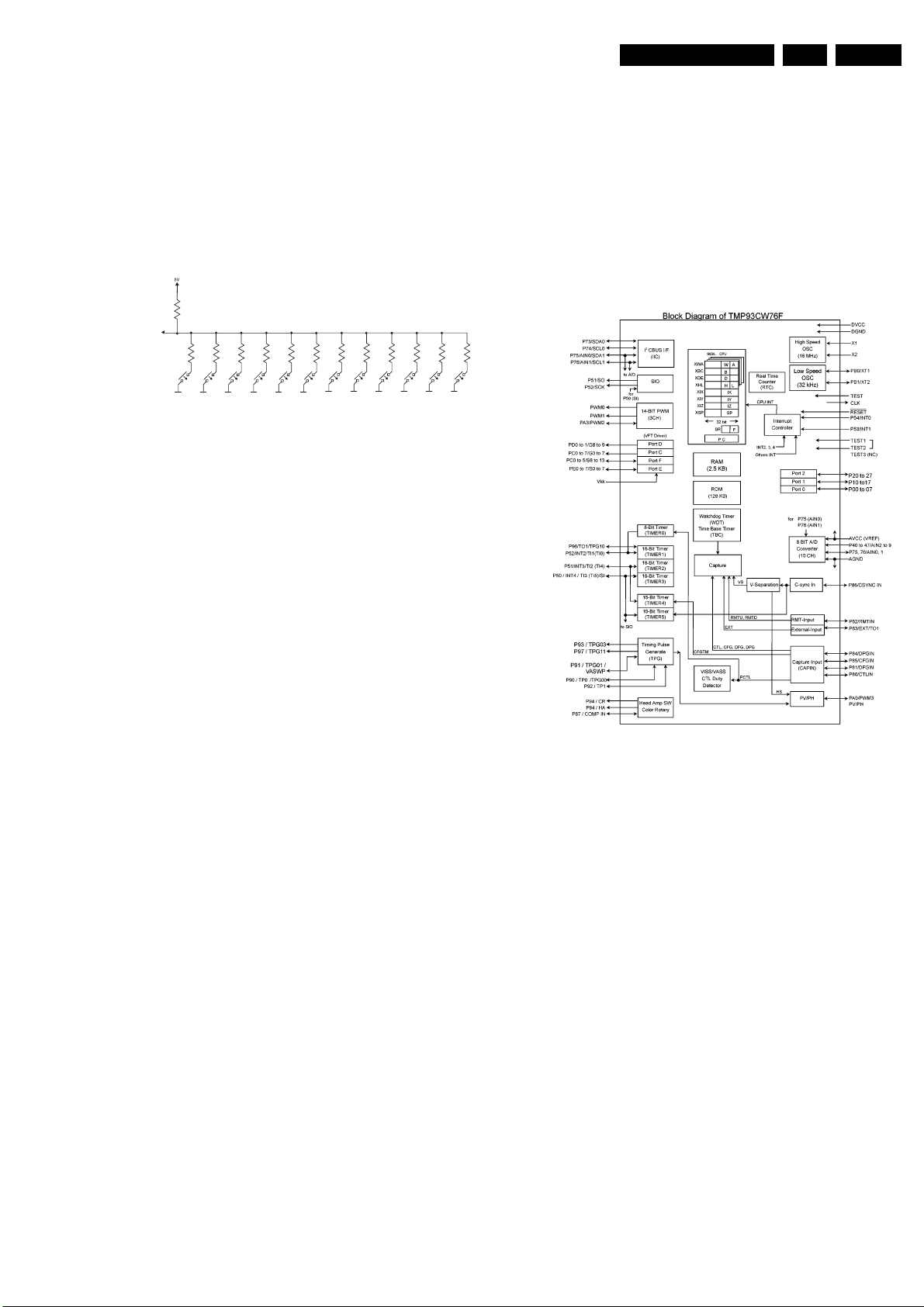
Circuit descriptions and List of abbreviations
GB 99VR120 9.
9.2.1 Evaluation of the keyboard matrix
There are 12 different keys. Each key function is assigned a
fixed voltage value. This value is decoded using an
analogue/digital (A/D) port (7899-B, pin 56). Each
mechanical key position on the printed board can adopt any
key function via a coding resistor. Pressing keys
simultaneously may lead to undesired functions!
Schematic:
10K
DC-KEY
[7899-B, pin56]
27K
47K
100K
REC
STBY
STOP
18K
STOP/EJECT
EJECT
12K
PLAY
5K6
WIND
REW
3K9
MONITOR
8K2
9.2.2 IR receiver and signal evaluation
The IR receiver [6170] includes a selective, controlled
amplifier in addition to a photo-diode. The photo-diode
changes the received transmission (approx. 940nm) in
electrical pulses, which are then amplified and demodulated.
On the output of the IR receiver [7220] a level lift 0V/5V pulse
sequence, which corresponds to the envelope curve of the
received IR remote control command, can be measured. This
pulse sequence is input into the controller for further signal
evaluation via input IRR [7899-B, pin 46].
9.3 Central Control AIO (AIO part)
The microcontroller (µC) TMP93CT76F [7899-B] includes
the following functions:
• PWM outputs
• A/D converters
• Composite sync input
• Special servo inputs for VCR functions
2
C-BUS interface
• I
• Shuttle evaluation
1K2
2K2
STILL
0E
470E
DOWN
UP
9.2.3 Activation and function of the VFD display
In principle, the VFD display [7170] is a tube triode in which
the heating filaments in the tube serve as cathodes (F+,F-).
The 7 grids (G1 - G7) are activated via PC2 - PC7, PD0 on
the controller, and the 16 anodes (P1 - P16) are controlled via
ports PE0 - PE7, PF0 - PF7, PC0, PC1 on the controller,
each with a positive potential compared to the cathode.
The grids and anodes (digits and symbols to be displayed)
are activated in the time-multiplex procedure, voltage lift 5V/
-18V. A dimmer function is generated using pulse-width
modulation of the grid control signals. At maximum display
brightness, the pulse width for each grid is 2.16 ms. It can be
reduced, controlled using software, which reduces the visual
brightness of the VFD display accordingly.
A digit or symbol is only illuminated if the corresponding
anode and the surrounding grid are switched simultaneously
to 5V for a certain time within a scanning period. The
electrons emitted from the cathode are accelerated by the
positively charged grid and hit the luminous layer of the
anode which is also positively charged.
During the remainder of the scanning period, the
corresponding grid and parts of the anode are at -18V, due to
the internal pull-down resistors in the controller. This
potential is still lower than the average cathode potential of
approx. -15V, prevents the acceleration of electrons, thus
causing the relevant grid and anode segments to go dark.
The heating direct voltage of the display (U = 3.5V) is
supplied from the power supply via lines HELO or HEHI to
pins F+ and F- to the VFD display. Resistors [3070] and
[3071] restrict F- to approx. -15V.
9.3.1 Analogue interface to the C:
The following analogue levels are supplied to the µ C’s
internal analogue/digital (A/D) converter:
• TAE/TAS Tape End / Tape Start Detection
• TRIV Tracking Information Video
• TRIA Tracking Information Audio
• AGC Automatic Gain Control
• AFC Automatic Frequency Control
• 8SC1/2 Pin 8 Scart1 or Scart2 switching
voltage
• Key-in Keypad evaluation
9.3.2 Tape end - LED control :
The LED current is switched using transistor [7804]. The ON
time is approx. 1 msec and the OFF time approx. 12 msec
during playback and 1msec to 5.5msec during the winding
functions.
The LED current is typically 150 mA. In order to prevent
interference from the relatively high pulsed current
‘spreading’ through the entire unit, the LED is fed from the
14VM1, and filtered by 2 resistors [3800, 3805] with 10R
each and a 220µF electrolytic capacitor [2803].
9.3.3 CMT detection (video detection with CSYNC)
This has been extended due to identification problems with
weak transmission signals and video signals not conforming
to the STANDARD (common channel interference). The
CSYNC line is supplied to the µP [7899-B] on pin 50. A
hardware integration [7807,7808,7809] of the video pulse
Page 100

GB 100 VR1209.
9
9
9
9
9
Circuit descriptions and List of abbreviations
compensates the interference generated by the common
channels and weak signals.
.3.4 EE-PROM
The EE-PROM [7818] is a non-volatile memory which can be
erased and written to electrically. (Data remains even if the
operating voltage fails). Data specific to the device such as
the X distance, head changeover position, preset stations,
optional bytes etc. is stored in the EE-PROM [7818]. The
data is accessed by the µP via the I
2
C bus.
.3.5 Easy link (P50)
For the communication between the TV set, video recorder
and the peripheral devices, a bi-directional single-wire bus is
used, which runs via pin 10 to scart socket 1.
The output signal is generated on pin 84 of the µC [7899-B],
pin 68 is the signal input.
.3.6 Shuttle
The shuttle is connected to the motherboard on plug
pos.1982. It is a binary coded rotary switch with a rotation
angle of +/- 70 degrees and 16 switch positions. These are
input and evaluated via four lines (shuttle b1 - shuttle b4) to
the input ports P24 - P27 [7899B pins 2-5].
this step-up. This creates an aperiodic transient response in
the resonance. Beyond the resonance frequency, there is an
adjustment in terms of a steep fall in the frequency
transmission characteristic. This effectively suppresses highfrequency pick-ups. The CTL head signal amplitude in
standard play is around 1mVp (typ.) which means that the
amplification for the playback amplifier must be
correspondingly high. To avoid offset problems, a 100 F
electrolytic capacitor [2490] is fitted in the negative feedback
branch for DC decoupling.
The polarity of the playback amplifier can be changed using
the Video Index Search System (VISS) voltage. This is the
only way in which the P can write a VISS mark on the tape
without spikes. The Write/Read (W/R) signal is used to
switch over between record and playback:
W = “H“, R = “L“.
9.4.2 Power on reset (POR) generator
The POR generator contained in the M63100FP [7463]
requires only one external capacitor [2477], which specifies
the length of the POR pulse. For 33 nF, t
POR
The response threshold of the reset circuit is between 4.5
and 4.8 V. Supply fluctuations which are shorter than tPOR/
100 area and which do not fall below 4.0 V, do not trigger the
POR. The P is reset using the inverted POR.
9.4.3 The sensor interface :
is approx. 30ms.
.3.7 Satmouse
For activating a sat-receiver via an external infrared
electronic transmission unit (Satmouse) a bi-directional data
line, a short-circuit proof +5V and earth are provided via a 3pin 3.5mm jack [1941].
The +5V is limited to approx. 140 mA using a current limiting
switch [7812 and peripherals].
9.4 Deck electronics DE (DE part)
The deck interface IC MP63100FP [7463] contains the
following functional groups:
• CTL stage (tape synchronisation)
• Sensor interface
• Power on reset
• Head drum motor driver
• Loading motor driver
• Capstan motor control
.4.1 CTL stage
The IC M63100FP [7463] contains a read/write stage for the
CTL track with the option of overwriting an existing CTL track
without any interference. The playback stage is fitted with a
“digital” five-stage AGC. This logic circuit identifies the size of
the output signal supplied by the CTL head, and then selects
the best amplification ratio in the playback stage using
comparators.
The CTL head voltage can therefore vary greatly, if V
is great. The slowest tape speed is in LP mode. The
V
min
fastest speed is adjusted during rewind. To ensure that the
duty cycle in the tape sync is always reproduced correctly in
the conditions mentioned above (important for detecting
VISS marks), the amplifier must not be overdriven.
The five-stage AGC alone cannot cover the large dynamic
range of the input voltage. The amplifier is therefore also
equipped with a low pass characteristic (fg = 3kHz typ.;
internal).
In parallel with the CTL head is the RC cell comprising
capacitor [2479] and resistor [3471]. The capacitor [2479],
together with the CTL head inductivity, causes a resonance
step-up at around 10 kHz and the resistor [3471] suppresses
max
The four comparators in the M63100FP [7463] are used to
convert sensor signals to the logic level. The outputs are
overload protected by a current limiter and thermal overload
protection. Only the non-inverting input on each comparator
is accessible from the outside. The other inputs are
connected to an internal reference of 2.5V. The fixed
hysteresis of the comparators of approx. 18 mV is also
located internally.
The comparators are connected as follows:
Comparator 1: In = FTA, pin 39; Out = FTAD, pin 34:
FTA = threading tachometer. This signal comes from a forked
light barrier in the deck. An infra-red light beam is interrupted
by a 4-blade impeller (butterfly). The output amplitude for the
light barriers should be less than 2V for the low level and
greater than 3V in the high level to ensure a correct
evaluation process. An additional hysteresis is created with a
resistor [3476]. For unit versions <1W and FOME the
external operation amplifier [7530B] is used to reduce the
power consumption in <1W mode.
Comparator 2: In = WTR, pin 38; Out = WTRD, pin 33:
WTR = Winding tachometer right, from a reflection
photoelectric barrier. The level is the same as for the FTA.
Comparator 3: In = WTL, pin 37; Out = WTLD, pin 31 :
WTL = Winding tachometer left, from a reflection
photoelectric barrier. The level is the same as for the FTA.
/
 Loading...