

Page 1
Antumbra
Installation Guide
Revision 02
Page 2

13 October, 2017
Antumbra 2 Product Overview
Page 3

13 October, 2017
Antumbra 3 Product Overview
Contents
Antumbra 1
1 Product Overview 5
1.1 Application Module 6
1.2 Communication Module 6
1.3 AntumbraButton 7
1.3.1 Product Architecture 7
1.3.2 Hardware Dimensions (EU) 8
1.3.3 Hardware Dimensions (NA) 8
1.3.4 Base Unit 9
1.4 AntumbraDisplay 10
1.4.1 Product Architecture 10
1.4.2 Hardware Dimensions (EU) 11
1.4.3 Hardware Dimensions (NA) 11
1.4.4 Base Unit 12
1.5 AntumbraTouch 13
1.5.1 Product Architecture 13
1.5.2 Hardware Dimensions (EU) 14
1.5.3 Hardware Dimensions (NA) 14
1.5.4 AntumbraTouch Base Unit 15
2 Installation 16
2.1 Network termination 16
2.2 Installation Procedure 17
2.2.1 Base Unit Installation 17
2.2.2 Antumbra shielding 20
2.2.3 Button Installation (AntumbraButton) 21
2.2.4 Button Installation (AntumbraDisplay) 22
2.2.5 Fascia Installation (AntumbraTouch) 23
3 Ordering Antumbra Panels 24
3.1 AntumbraButton 24
3.1.1 Spare Parts 25
3.2 AntumbraDisplay 26
3.2.1 Spare Parts 27
3.3 AntumbraTouch 28
3.3.1 Spare Parts 29
Page 4

13 October, 2017
Antumbra 4 Product Overview
About this Guide
Guide Overview
This guide is designed to assist in the ordering and installation of the Antumbra Panel user
interface.
A working knowledge of Dynalite commissioning processes is required to effectively use this
document. For more information on commissioning processes, consult the Antumbra
Commissioning Guide.
Disclaimer
These instructions have been prepared by Philips Dynalite and provide information on Philips
Dynalite products for use by registered owners. Some information may become superseded
through changes to the law and as a result of evolving technology and industry practices.
Any reference to non-Philips Dynalite products or web links does not constitute an
endorsement of those products or services
Copyright
© 2017 Dynalite manufactured by WMGD Pty Ltd (ABN 33 097 246 921). All rights
reserved. Not to be reproduced without permission. Dynalite, Dimtek, DLight, DyNet and
associated logos are the registered trademarks of WMGD Pty Ltd.
Page 5
13 October, 2017
Antumbra 5 Product Overview
1 Product Overview
The Philips Dynalite Antumbra Panel series is a unique and stylish range of user interfaces,
combining contemporary design with superior functionality to enable intuitive control of
lighting, HVAC and other connected devices and systems.
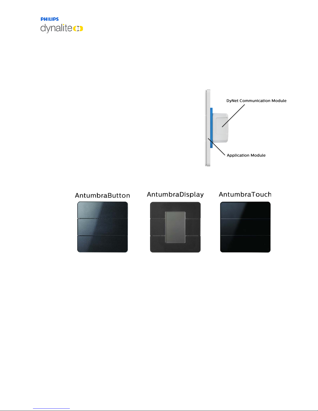
The Antumbra Panel series is one of the most
flexible user interface solutions available in the
market. Advanced flexibility is achieved by dividing
the panel into two components; the Application
Module, which contains the panel’s buttons and
sensors, and the DyNet Communication Module,
which handles all onboard logic and network
communication. Each of these components is
described in detail later on the next page.
The Antumbra Panel series has been designed to suit
both residential and commercial applications. The
series consists of the following panel variants in both European (square) and US/Australian
(rectangular) styles:
Each button on the Antumbra panel can be configured using the EnvisionProject
commissioning software to perform a vast range of functions.
In addition to its six buttons, the Antumbra panel contains three sensors:
Proximity sensor
The Proximity sensor utilizes capacitive field effect technology to detect motion. When a
user approaches the panel, it initiates a wall-wash lighting effect to encourage interaction.
Ambient light sensor
An internal light sensor measures ambient light to adjust lightwash effect accordingly.
Temperature sensor
The temperature sensor is used to monitor the temperature of the room where the panel is
mounted.
Page 6
13 October, 2017
Antumbra 6 Product Overview
1.1 Application Module
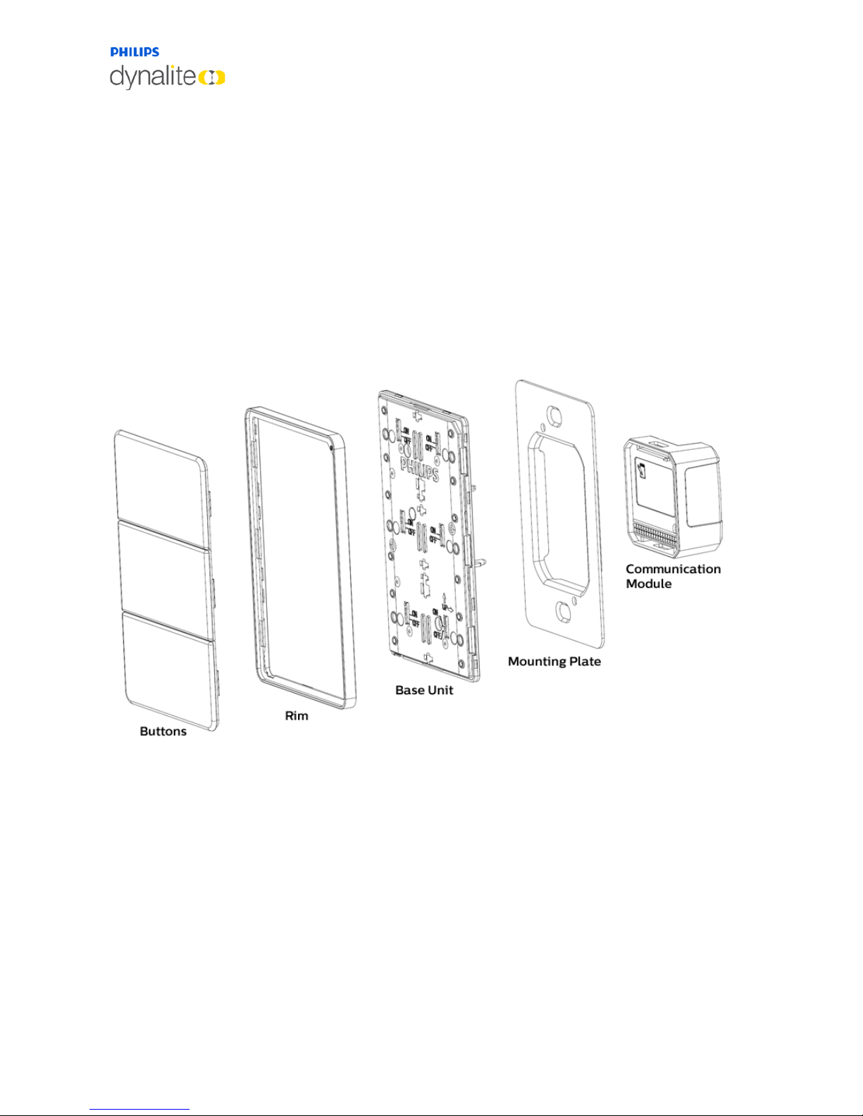
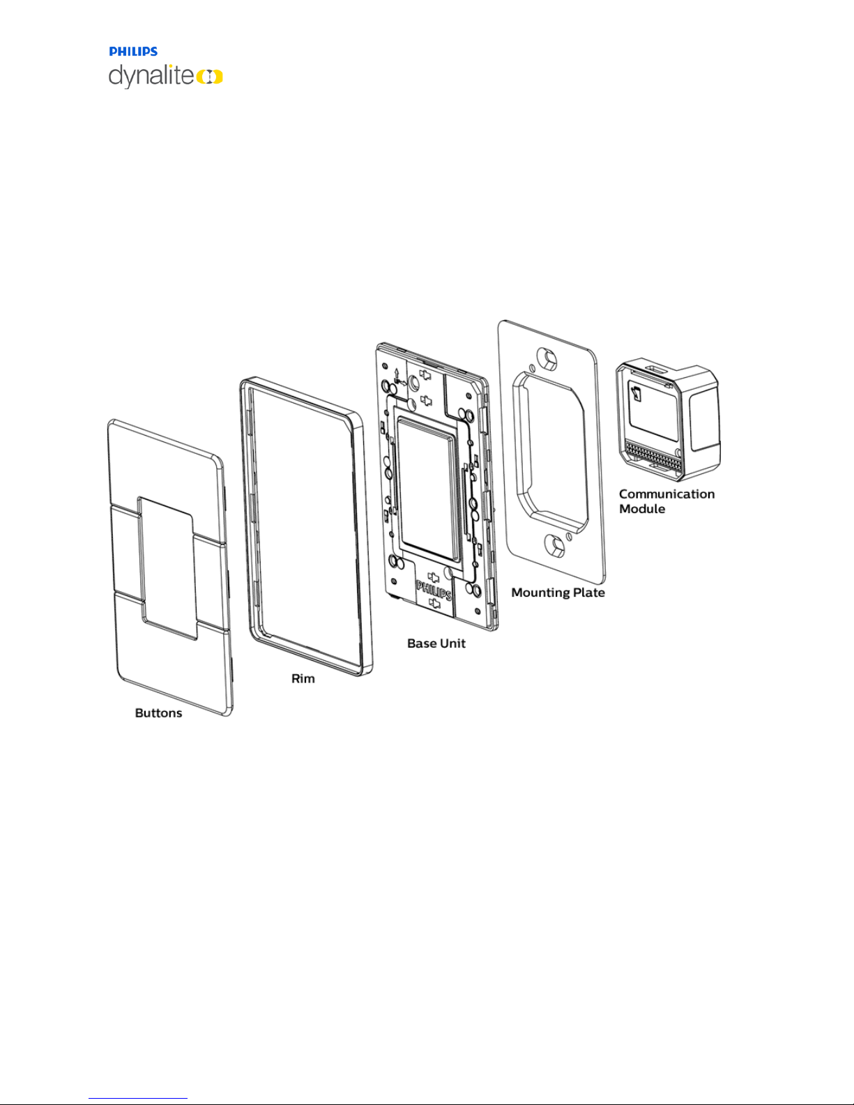
The Application Module consists of the buttons, rim, base unit and mounting plate. The
buttons/touch panel and rims of each Antumbra unit come in different colours and finishes.
The rim has built-in ventilation to increase the responsiveness of the temperature sensor.
The Base unit contains all the sensor devices and the LEDs. It includes the proximity,
daylight and temperature sensors. The LEDs are used to provide backlight to the configured
buttons on the panel, and to produce the light wash effect around the panel.
1.2 Communication Module
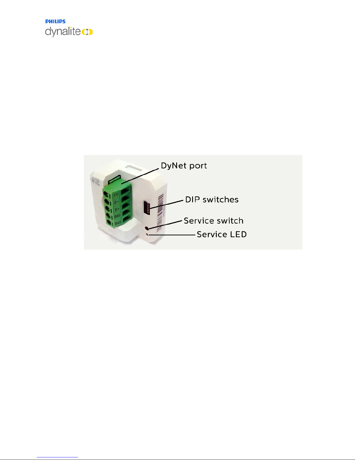
The DyNet communication module is common across the Antumbra series. It contains all
the logical and network functions required by the panel.
The communication module contains all the panel’s settings and manages the communication
to the DyNet network.
The communication module can be pre-programmed using EnvisionProject without the
application module present, and is capable of running complex tasks based on timeclock
signals, DyNet messages such as presets or commands, and the position of the six DIP
switches shown in the picture above.
For example, in a hotel installation with a set of identical configurations for multiple rooms,
the same software settings can be programmed on each communication module, and the
installer need only select the panel’s area number using the correct DIP switch settings
before installing.
The service switch can be used to test the network. A long press resets the Comms Module
and a short press sends a sign-on message on to the DyNet network.
For more information regarding communication module termination and operation can be
found in the Installation – Network Termination section.
Page 7
13 October, 2017
Antumbra 7 Product Overview
1.3 AntumbraButton
The AntumbraButton panel has an RS485 DyNet serial port and is classified as a Class 2
Safety Extra-Low Voltage (SELV) device.
The AntumbraButton panel is available in white, silver, magnesium and brushed aluminium
button finishes. To complement these button finishes, rim finishes are available in white,
magnesium, chrome and brushed aluminium, providing a wide range of décor matching
possibilities.
Custom labelling of icons and engraved text is available for each panel.
1.3.1 Product Architecture
Page 8
13 October, 2017
Antumbra 8 Product Overview
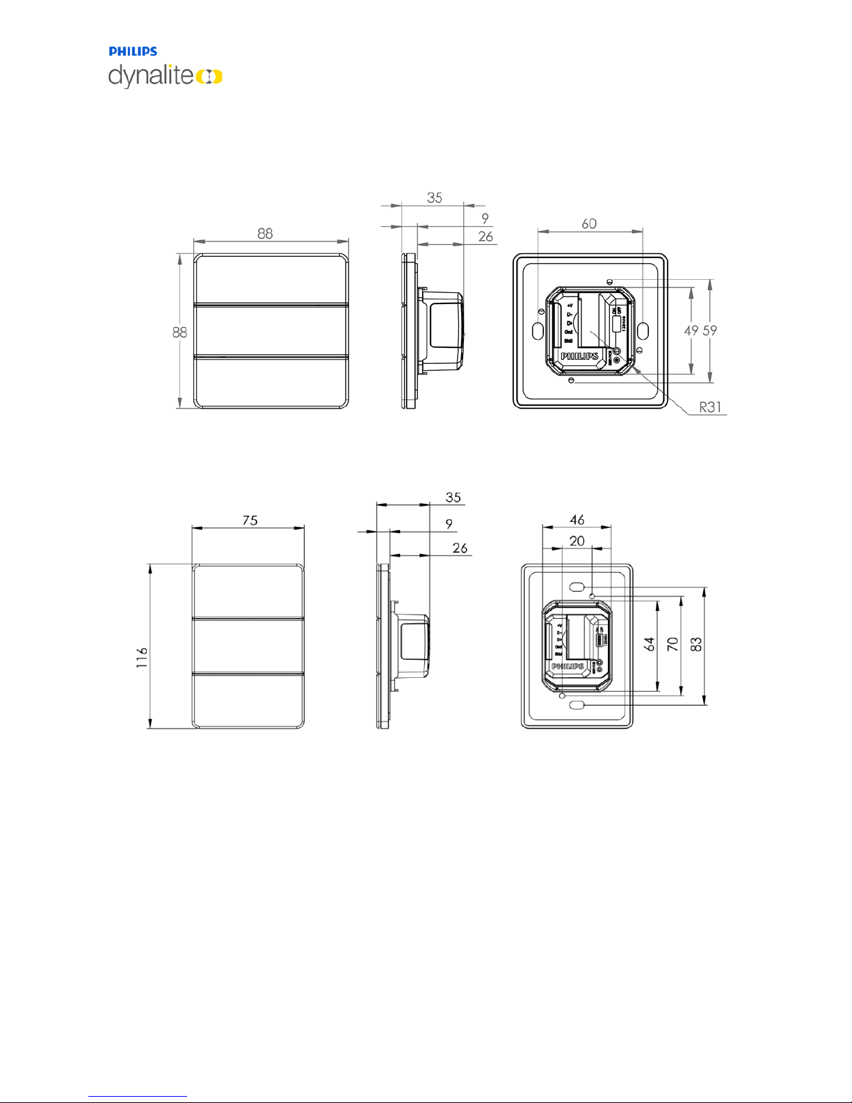
1.3.2 Hardware Dimensions (EU)
1.3.3 Hardware Dimensions (NA)
Page 9
13 October, 2017
Antumbra 9 Product Overview
1.3.4 Base Unit
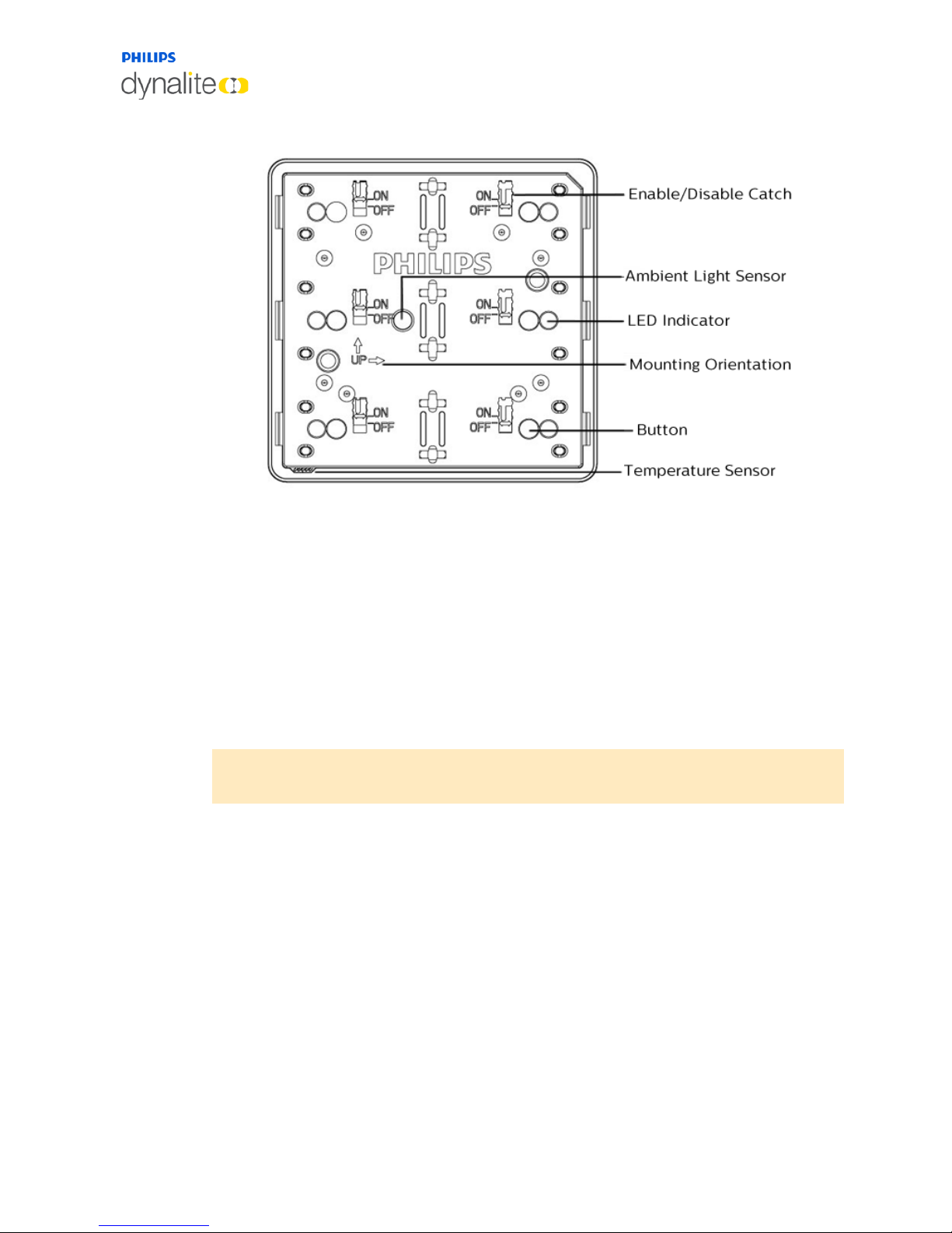
The AntumbraButton Panel application module consists of six configurable buttons, indicator
and backlight LEDs, a temperature sensor, an ambient light sensor and a proximity sensor.
Each button has an enable/disable catch that can be used to enable/disable the tactile feel of
the buttons on the panel.
Refer to the ‘up’ arrows on the application module to indicate the side that has to be at the
top when the panel is mounted in either portrait or landscape orientation.
When attaching the rim, ensure that the holes on the rim are positioned over the
temperature sensor.
Note: To remove the buttons from the panel, lift the button edge on the left and right side
of the panel before lifting the button at the center.
Page 10
13 October, 2017
Antumbra 10 Product Overview
1.4 AntumbraDisplay
The AntumbraDisplay Panel has a RS485 DyNet serial port and is classified as a Class 2
Safety Extra-Low Voltage (SELV) device.
This panel is available in white, silver, magnesium and brushed aluminium button finishes.
Complementary rim finishes are available in white, magnesium, chrome and brushed
aluminium, providing a wide range of décor matching possibilities.
1.4.1 Product Architecture
Page 11
13 October, 2017
Antumbra 11 Product Overview
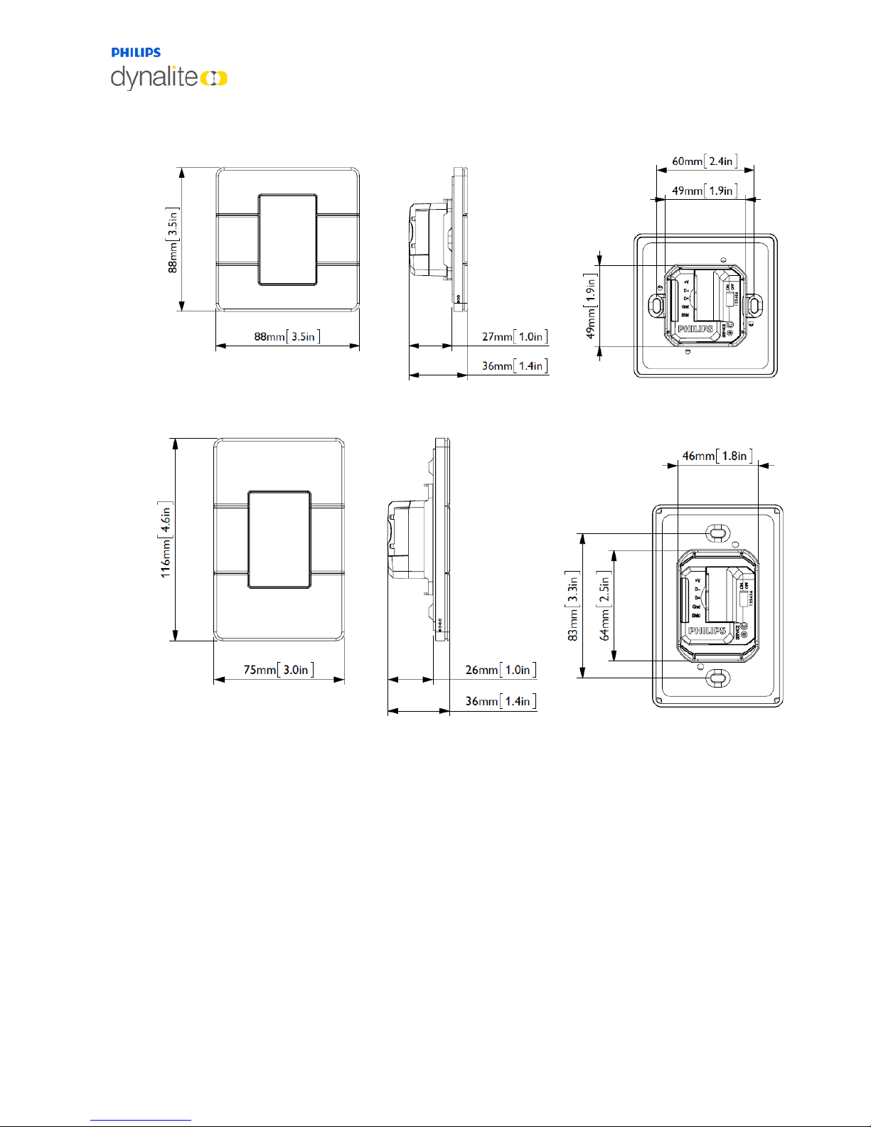
1.4.2 Hardware Dimensions (EU)
1.4.3 Hardware Dimensions (NA)
Page 12
13 October, 2017
Antumbra 12 Product Overview
1.4.4 Base Unit
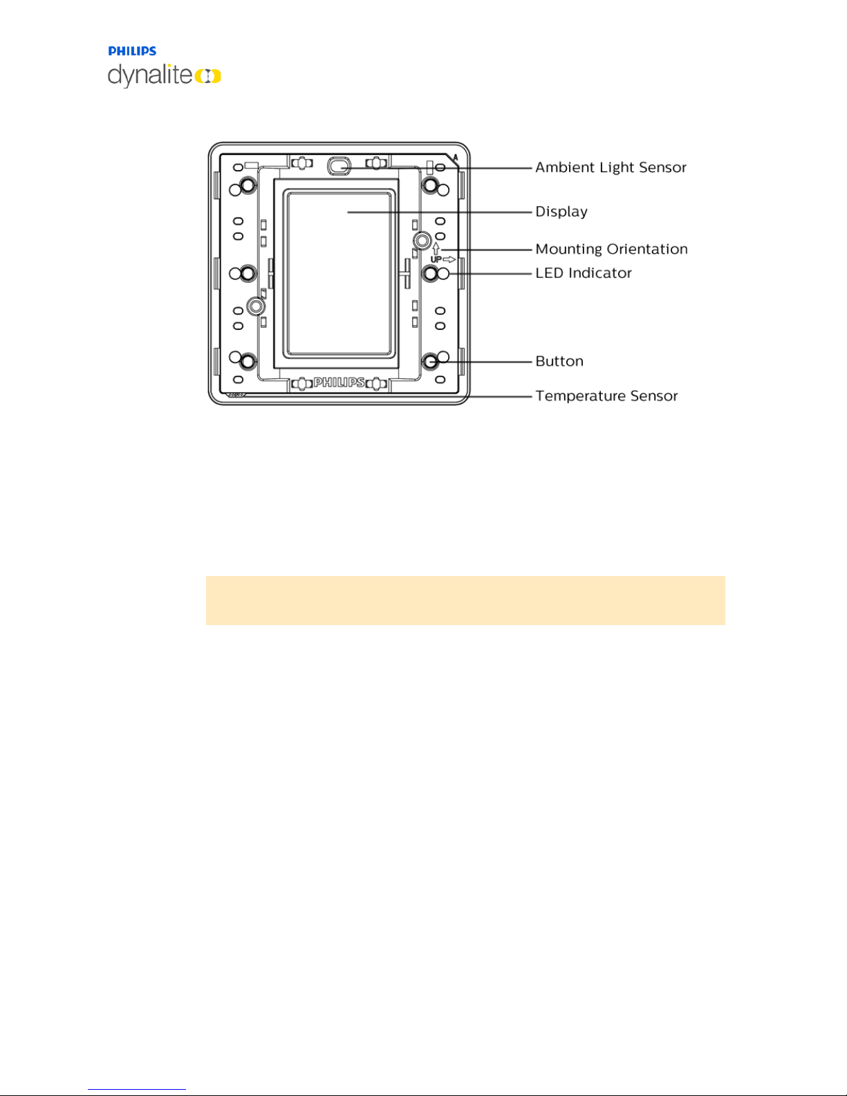
The AntumbraDisplay Panel application module consists of six buttons, LED indicators, a
temperature sensor, an ambient light sensor and a proximity sensor.
Refer to the ‘up’ arrows on the application module to indicate the side that has to be at the
top when the panel is mounted in either portrait or landscape orientation.
When attaching the rim, ensure that the holes on the rim are positioned over the
temperature sensor.
Note: To remove the buttons from the panel, lift the button from the left and/or
right edge of the panel before lifting the button at the center.
Page 13
13 October, 2017
Antumbra 13 Product Overview
1.5 AntumbraTouch
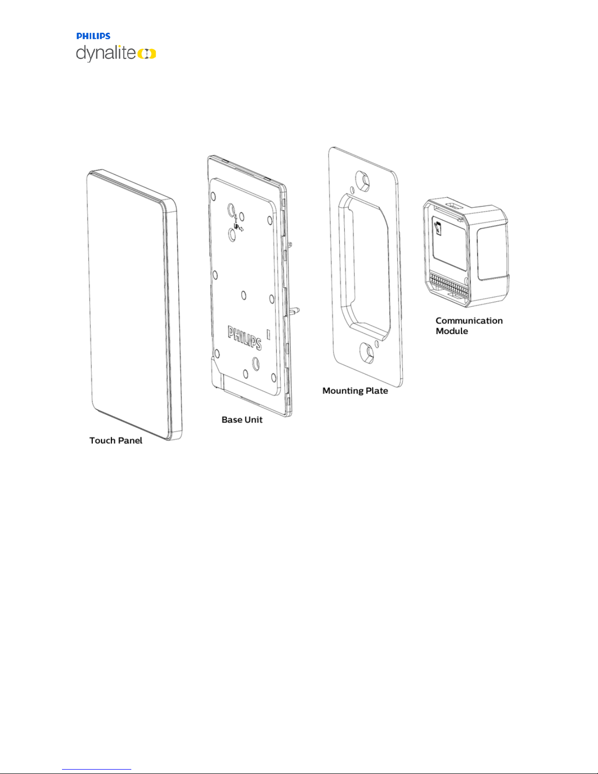
1.5.1 Product Architecture
The touch surface and rim of the AntumbraTouch panel are supplied pre-attached. The
touch surface is available in black or white.
The rim is available in black, white, chrome or brushed aluminium finishes, and has
ventilation holes on one corner to expose the temperature sensor to the air. For this
reason it is important to ensure that the touch surface is mounted in the correct
orientation.
The base unit contains the panel’s sensor devices, buzzer and LEDs. It includes the proximity
sensor, the daylight sensor and the temperature sensor. The LEDs are used to provide
backlight to the buttons, and to create the lightwash effect around the panel.
Page 14
13 October, 2017
Antumbra 14 Product Overview
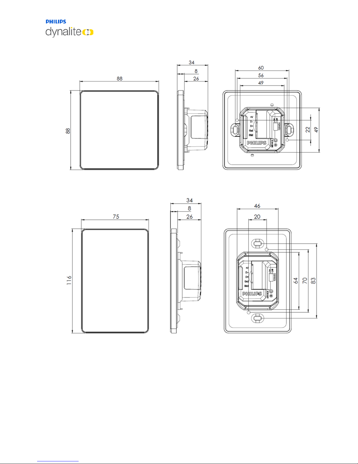
1.5.2 Hardware Dimensions (EU)
1.5.3 Hardware Dimensions (NA)
Page 15
13 October, 2017
Antumbra 15 Installation
1.5.4 AntumbraTouch Base Unit
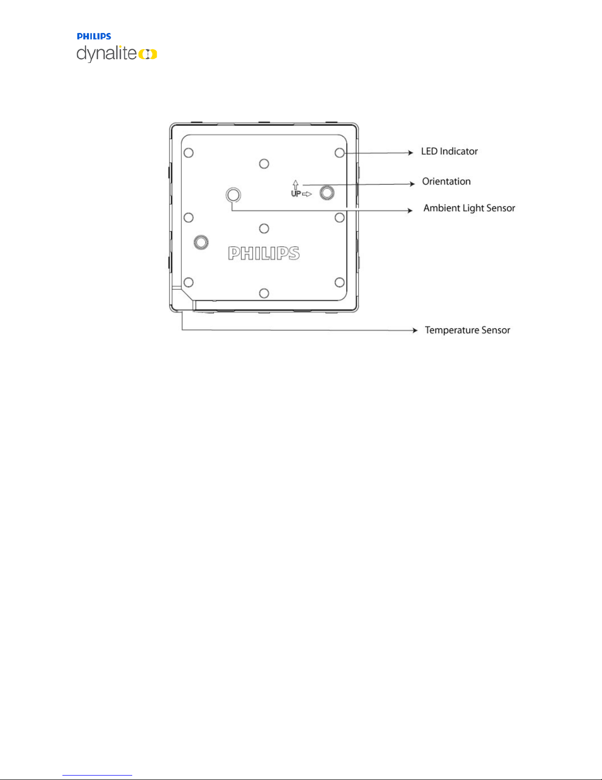
The AntumbraTouch Application Module has six configurable touch points, LED indicators, a
temperature sensor, a daylight sensor and a proximity sensor.
The panel can be mounted in both portrait and landscape orientations. Ensure the holes on
the rim are positioned over the temperature sensor to allow airflow. The arrows indicate
the side that has to be at the top when the panel is mounted.
Page 16
13 October, 2017
Antumbra 16 Installation
2 Installation
2.1 Network termination
NOTE: Never connect network devices to a live network. Power down all load controllers
and network power supplies before connecting devices or adjusting the DyNet network.
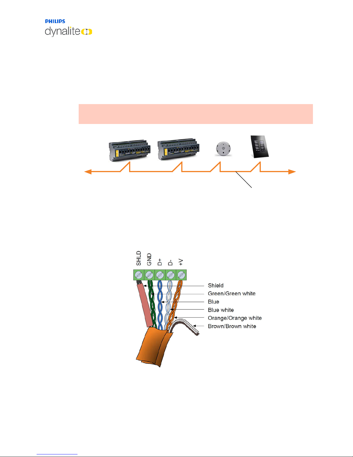
Unplug the five way screw socket on the back of the Communication module. Terminate the
network cable following the diagram below. All devices must be terminated correctly as
shown.
DyNet Network
DyNet RS
485
3 Twisted Pair
& Overall
Screen
Page 17
13 October, 2017
Antumbra 17 Installation
2.2 Installation Procedure
The following installation procedure applies to all Antumbra panel variants.
Antumbra panels are powered from the DyNet network, which is classified as SELV/Class II
(for NA) Overvoltage category III in accordance with IEC60664-1(0.8 kV surge).
Ensure that installation of the Antumbra Panel is in compliance with HD 60364 - 4I where
applicable.
Caution: Use approved DyNet power supplies only with incorporated overload protection.
Disconnect DyNet before attaching the communication module to the application module.
2.2.1 Base Unit Installation
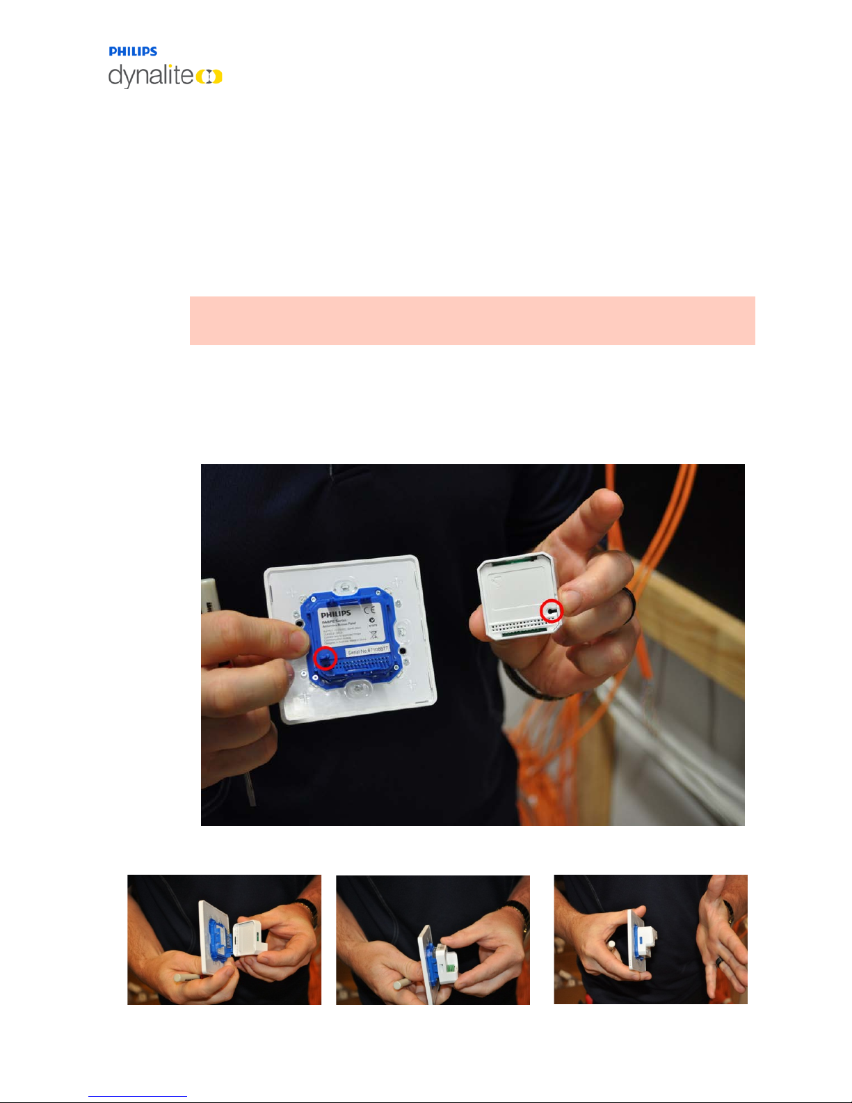
The communication module and application module lock in together when the locating pin
on the Application module lines up with the locating socket on the communication module
(circled below).
Page 18
13 October, 2017
Antumbra 18 Installation
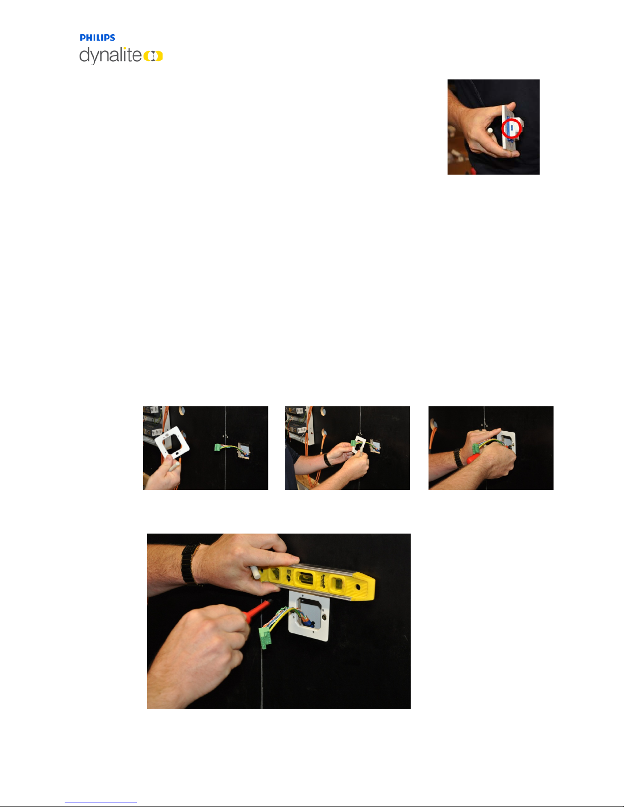
To separate the communication module and application module,
use a small screw driver to gently unlock the two clips on either
side of the communication module.
The mounting plate fits any standard size European wall box or a wall cut out of 51mm x
51mm. If using wall mounting then the smaller base mounting screw locations should also
have a small indent behind them, made into the wall so there is no interference from the
screws while mounting the panel. The Mounting box must have a depth of 33mm to contain
all the panel components and network cabling. Remember that there will be a need for two
network cables in the wall box.
1. The mounting plate needs to be installed with the locating tabs into the wall.
2. The network cables and connector plug pulls though the mounting bracket.
3. The plate’s orientation can be either way. Using the long mounting screws provided, fix
the mounting bracket to the wall. Installers must use the screws provided as different
screws could damage the panel once fully installed.
1 2 3
4. Ensure that the mounting plate is level and adjust if required.
Page 19
13 October, 2017
Antumbra 19 Installation
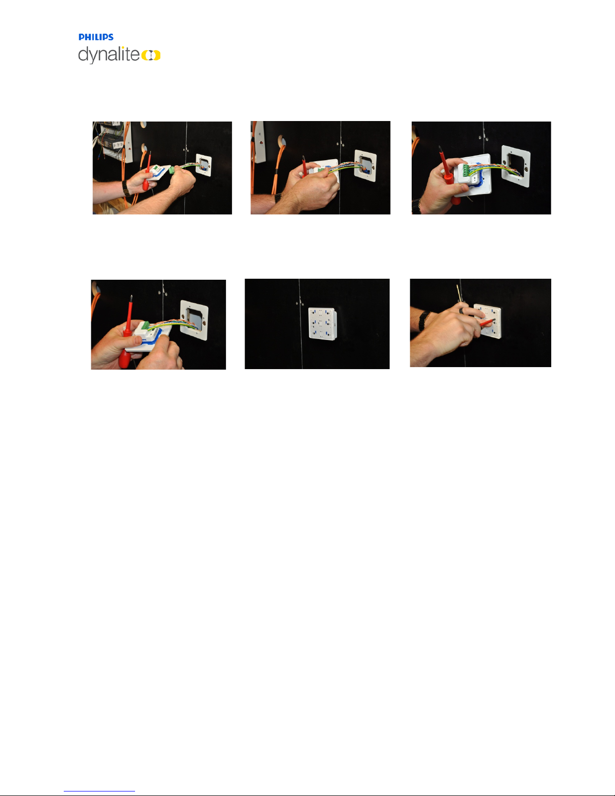
5. Once the mounting plate is secured, plug the phoenix connector into the
communication module. If the communication module is not already attached to the
application module, attach it now.
6. Push the panel assembly into the mounting bracket. Locate and fix the application unit to
the mounting bracket using the two smaller screws through the mounting holes.
Recheck the level of the panel and adjust if required
Page 20
13 October, 2017
Antumbra 20 Installation
2.2.2 Antumbra shielding
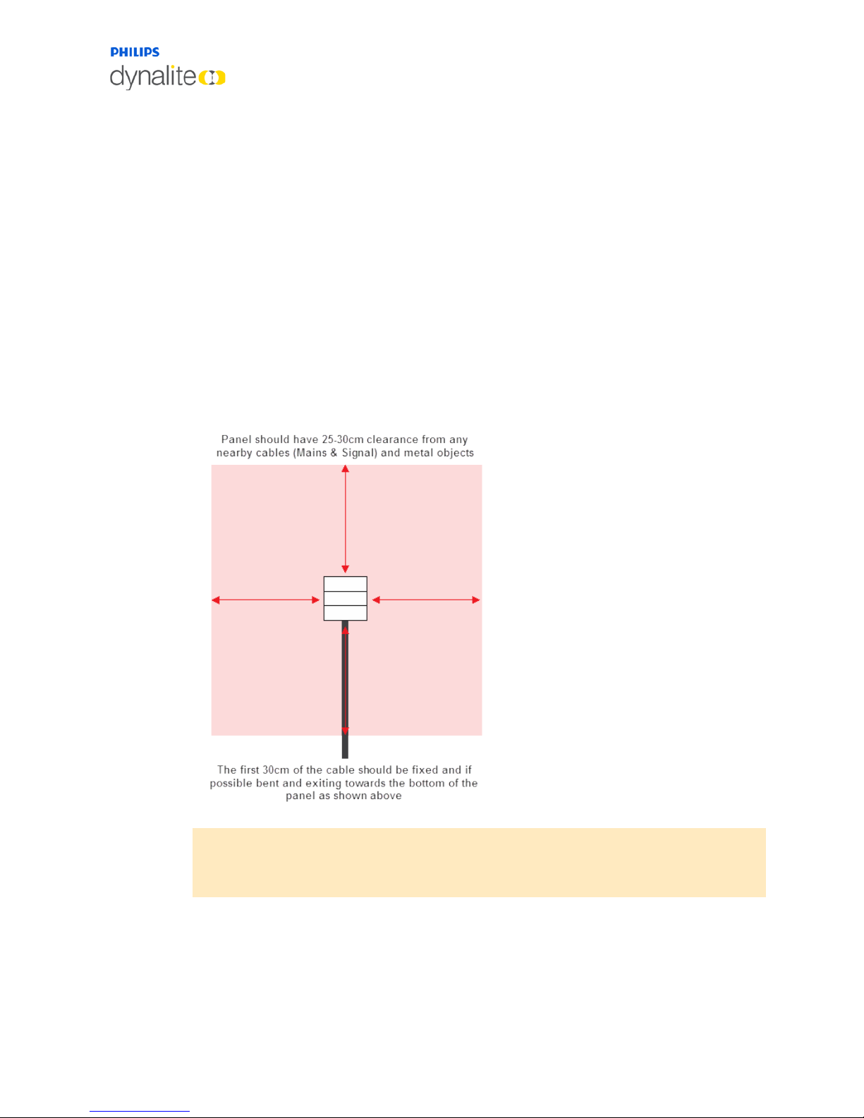
False triggering of the proximity sensor may occur if the shield terminal is not connected to
the wall box or metal mounting plate. False triggering of the Proximity Sensor can be
prevented by ensuring the following points are considered during installation:
• Surrounding cables are at a minimum distance of 25-30 cm away from the panel.
• The first 30 cm of the cable connected to the panel is fixed. The cable should not
move.
• The preferable cable exit after connection to the terminal block is towards the
bottom of the panel as it does not have the proximity sensing pad
• Avoid installing the panel closer than 30 cm from any metal object and other control
panels of the same or different type as it may affect the proximity sensing range and
cause false triggering.
Note: Do not install panels near windows, sources of heat and air-condition ventilation
outlets, also do not expose them to direct sunlight as all these factors may affect
temperature sensing performance.
Page 21
13 October, 2017
Antumbra 21 Installation
2.2.3 Button Installation (AntumbraButton)
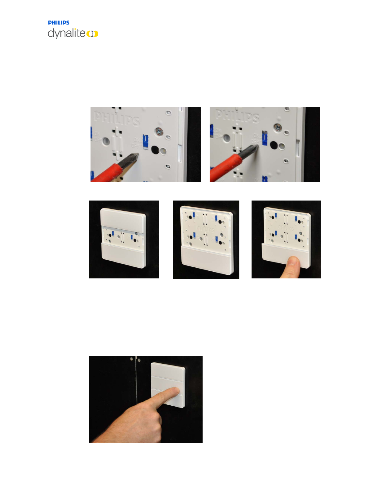
Individual buttons can be disabled if a particular panel location does not require all six
buttons to be used. By using the blue switches and buttons, mechanical action can be
switched on or off.
Disable the mechanical action of unused buttons by setting the blue switch to OFF.
Off On
After ensuring that the correct buttons are enabled or disabled as required, attach the
buttons to the application module. Carefully line up each button with the application
module, then press the center of the button until it clicks into place. Press each side of the
button into place.
Once correctly attached, enabled buttons will have a smooth tactile click when pressed. If
any enabled button does not have a positive click when pressed, check for obstructions or
the disable switch being set incorrectly.
Page 22
13 October, 2017
Antumbra 22 Installation
2.2.4 Button Installation (AntumbraDisplay)
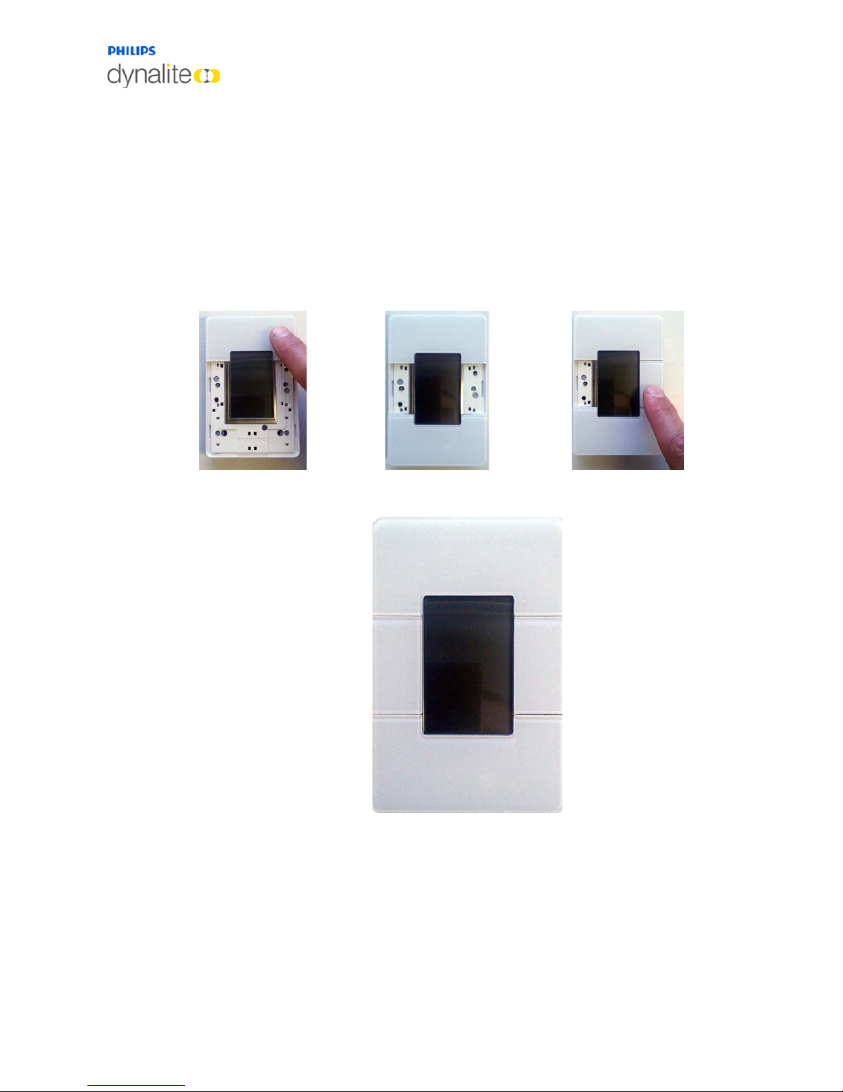
This panel has two large buttons and two small buttons that fit around the display.
To attach the large buttons, carefully line up each button with the application module, then
press the center of the button until it clicks into place. Press each side of the button into
place.
To attach the small buttons, ensure that the raised ridge on each button is aligned with the
corresponding space between the application module and the rim. Press down on the top
and bottom of the button until it clicks into place.
Once correctly attached, each button will have a smooth tactile click when pressed.
Page 23
13 October, 2017
Antumbra 23 Ordering Antumbra Panels
2.2.5 Fascia Installation (AntumbraTouch)
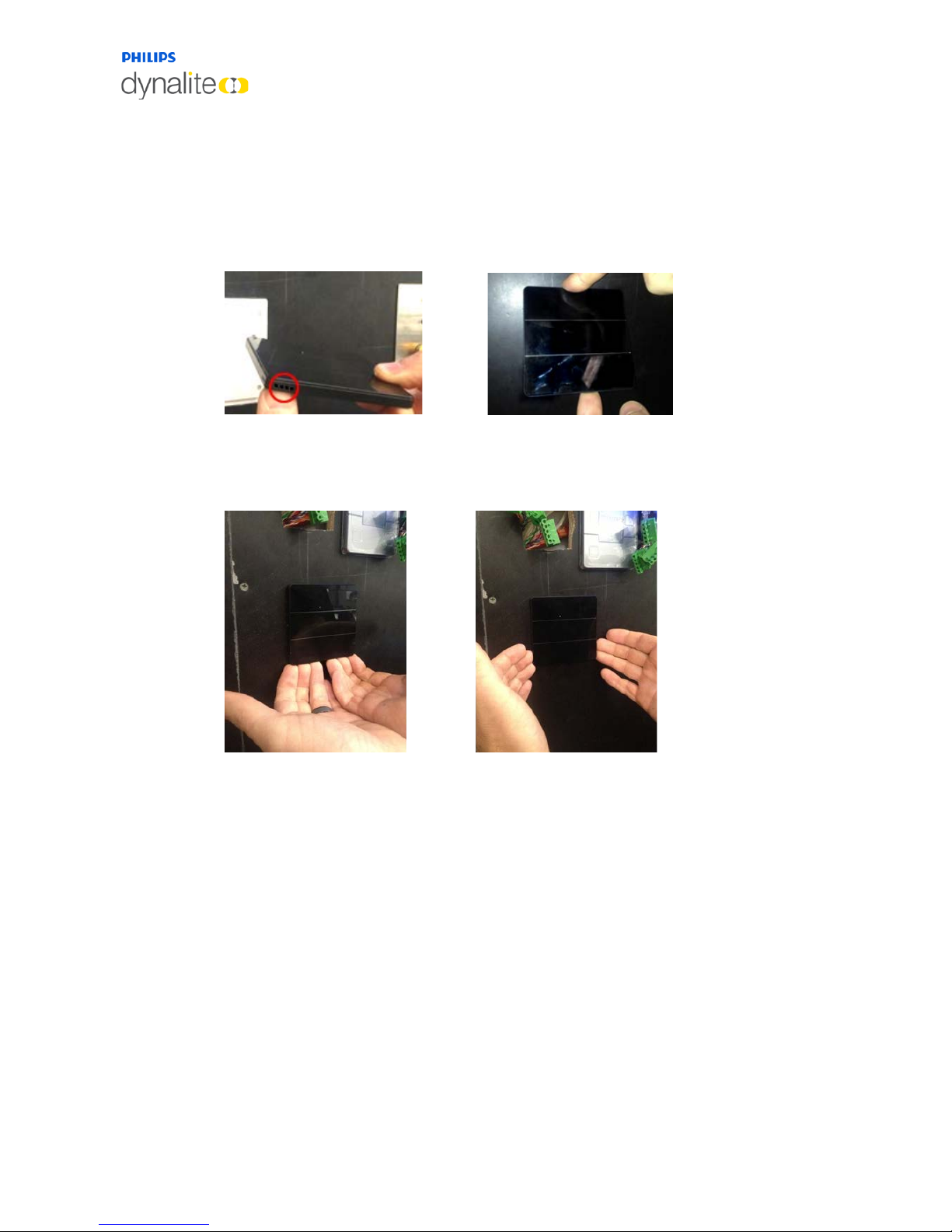
The rim and glass fascia for the AntumbraTouch panel are supplied as a single piece.
Ensure that the air vent on the rim, shown below, is placed over the temperature sensor on
the application module. Place the glass face on the application base and gently press it to fix
the panel to the base.
To remove the glass face from the application base, loosen the glass face from the bottom
and then the sides and later lift it from the application base. The pictures below show the
correct way of removing the glass face from the application base.
Page 24
13 October, 2017
Antumbra 24 Ordering Antumbra Panels
3 Ordering Antumbra Panels
The Antumbra panel is split into two parts, the Application module and the Communication
module. These two units are ordered separately. Both of these units are required for a
complete installation.
The Application module is available in multiple button and rim finishes, as
detailed throughout this chapter. Labelling options are also available for
the AntumbraButton and AntumbraTouch variants to detail button
functionality.
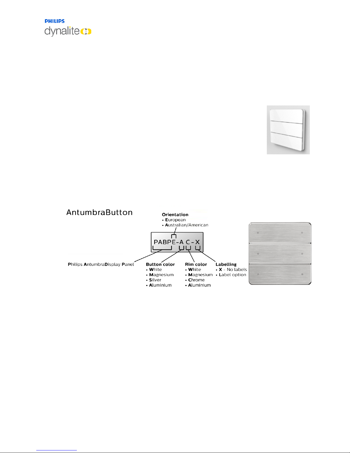
Antumbra panels are ordered using part numbers that detail the selected
product options, as illustrated on the following page.
3.1 AntumbraButton
The part number shown here describes a European style AntumbraButton panel with
brushed aluminium buttons, chrome rim and no button labelling:
Page 25

13 October, 2017
Antumbra 25 Ordering Antumbra Panels
3.1.1 Spare Parts
This table shows the part numbers for AntumbraButton spares:
Description
Profile
Color
Custom
Part Number code
Spare - Antumbra Button
EU White no PABSE-WX-X
Spare - Antumbra Button
EU White yes PABSE-WX-L
Spare - Antumbra Button
EU Silver no PABSE-SX-X
Spare - Antumbra Button
EU Silver yes PABSE-SX-L
Spare - Antumbra Button
EU Magnesium no PABSE-MX-X
Spare - Antumbra Button
EU Magnesium yes PABSE-MX-L
Spare - Antumbra Button
EU Aluminum no PABSE-AX-X
Spare - Antumbra Button
EU Aluminum yes PABSE-AX-L
Spare - Antumbra Button
NA White no PABSA-WX-X
Spare - Antumbra Button
NA White yes PABSA-WX-L
Spare - Antumbra Button
NA Silver no PABSA-SX-X
Spare - Antumbra Button
NA Silver yes PABSA-SX-L
Spare - Antumbra Button
NA Magnesium no PABSA-MX-X
Spare - Antumbra Button
NA Magnesium yes PABSA-MX-L
Spare - Antumbra Button
NA Aluminum no PABSA-AX-X
Spare - Antumbra Button
NA Aluminum yes PABSA-AX-L
Spare - Button Rim
EU White N/A PABSE-XW
Spare - Button Rim
EU Aluminum N/A PABSE-XA
Spare - Button Rim
EU Chrome N/A PABSE-XC
Spare - Button Rim
EU Magnesium N/A PABSE-XM
Spare - Button Rim
NA White N/A PABSA-XW
Spare - Button Rim
NA Aluminum N/A PABSA-XA
Spare - Button Rim
NA Chrome N/A PABSA-XC
Spare - Button Rim
NA Magnesium N/A PABSA-XM
Spare - Button Application Module Kit
EU N/A N/A PABSE-AMK
Spare - Button Application Module Kit
NA N/A N/A PABSA-AMK
Spare - Antumbra Mounting Grid
EU N/A N/A PABSE-GRID
Spare - Antumbra Mounting Grid
NA N/A N/A PABSA-GRID
Spare - Antumbra Mounting Screws Kit
EU N/A N/A PABSE-SCREWS
Spare - Antumbra Mounting Screws Kit
NA N/A N/A PABSA-SCREWS
Sales Demo Kit - BUTTON
EU N/A N/A PABSE-DEMOPACK
Sales Demo Kit - BUTTON
NA N/A N/A PABSA-DEMOPACK
Page 26
13 October, 2017
Antumbra 26 Ordering Antumbra Panels
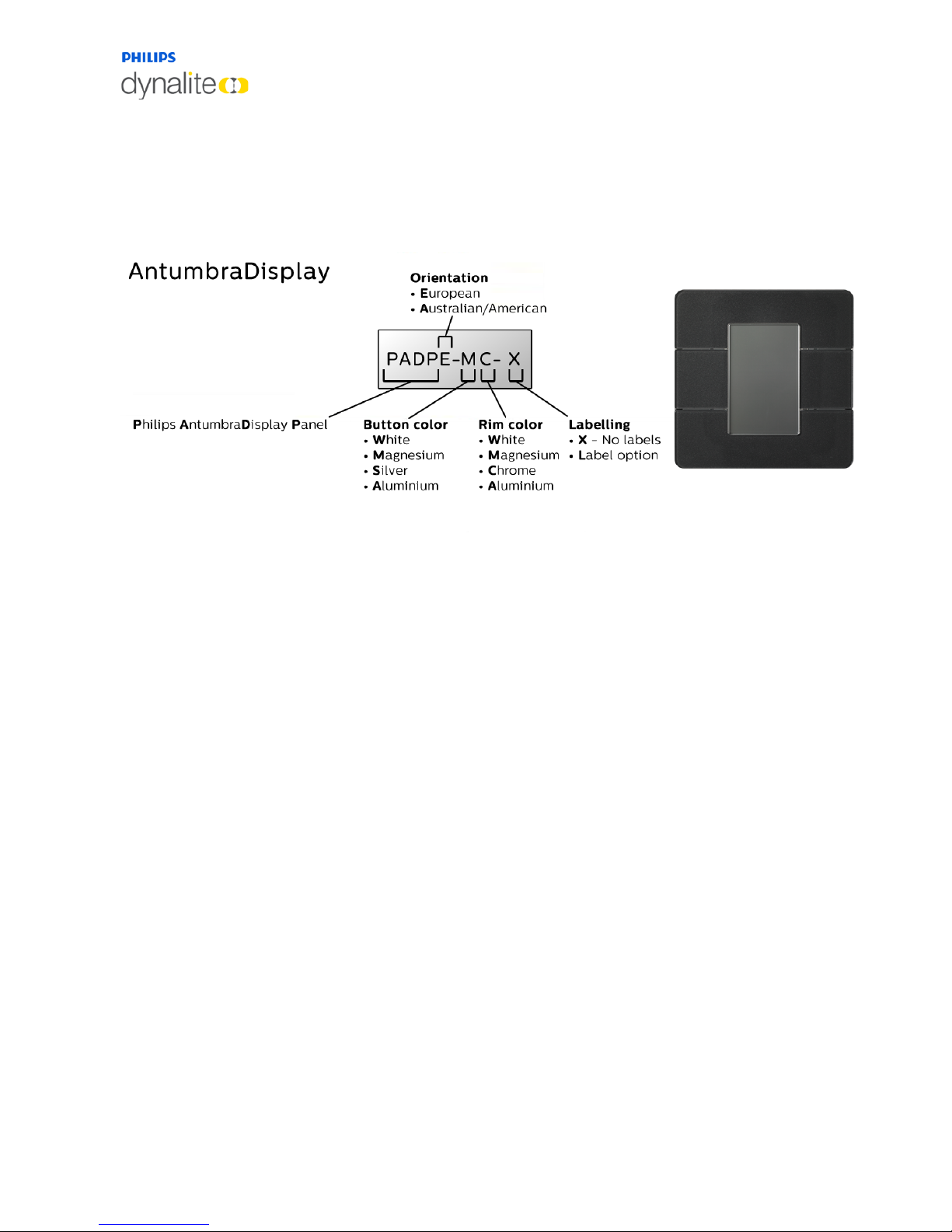
3.2 AntumbraDisplay
This part number describes a European style AntumbraDisplay panel with magnesium
buttons, chrome rim and no button labelling.
Page 27

13 October, 2017
Antumbra 27 Ordering Antumbra Panels
3.2.1 Spare Parts
This table shows the part numbers for AntumbraDisplay spares:
Description
Profile
Color
Part Number code
Spare - Display Button
EU White PADSE-WX
Spare - Display Button
EU Silver PADSE-SX
Spare - Display Button
EU Magnesium PADSE-MX
Spare - Display Button
EU Aluminum PADSE-AX
Spare - Display Button
NA White PADSA-WX
Spare - Display Button
NA Silver PADSA-SX
Spare - Display Button
NA Magnesium PADSA-MX
Spare - Display Button
NA Aluminum PADSA-AX
Spare - Display Rim
EU White PADSE-XW
Spare - Display Rim
EU Aluminum PADSE-XA
Spare - Display Rim
EU Chrome PADSE-XC
Spare - Display Rim
EU Magnesium PADSE-XM
Spare - Display Rim
NA White PADSA-XW
Spare - Display Rim
NA Aluminum PADSA-XA
Spare - Display Rim
NA Chrome PADSA-XC
Spare - Display Rim
NA Magnesium PADSA-XM
Spare - Display Application Module Kit
EU N/A PADSE-AMK
Spare - Display Application Module Kit
NA N/A PADSA-AMK
Sales Demo Kit - DISPLAY
EU N/A PADSE-DEMOPACK
Sales Demo Kit - DISPLAY
NA N/A PADSA-DEMOPACK
Spare - Display Button
EU White PADSE-WX
Spare - Display Button
EU Silver PADSE-SX
Spare - Display Button
EU Magnesium PADSE-MX
Spare - Display Button
EU Aluminum PADSE-AX
Spare - Display Button
NA White PADSA-WX
Spare - Display Button
NA Silver PADSA-SX
Spare - Display Button
NA Magnesium PADSA-MX
Spare - Display Button
NA Aluminum PADSA-AX
Spare - Display Rim
EU White PADSE-XW
Spare - Display Rim
EU Aluminum PADSE-XA
Spare - Display Rim
EU Chrome PADSE-XC
Spare - Display Rim
EU Magnesium PADSE-XM
Page 28
13 October, 2017
Antumbra 28 Ordering Antumbra Panels
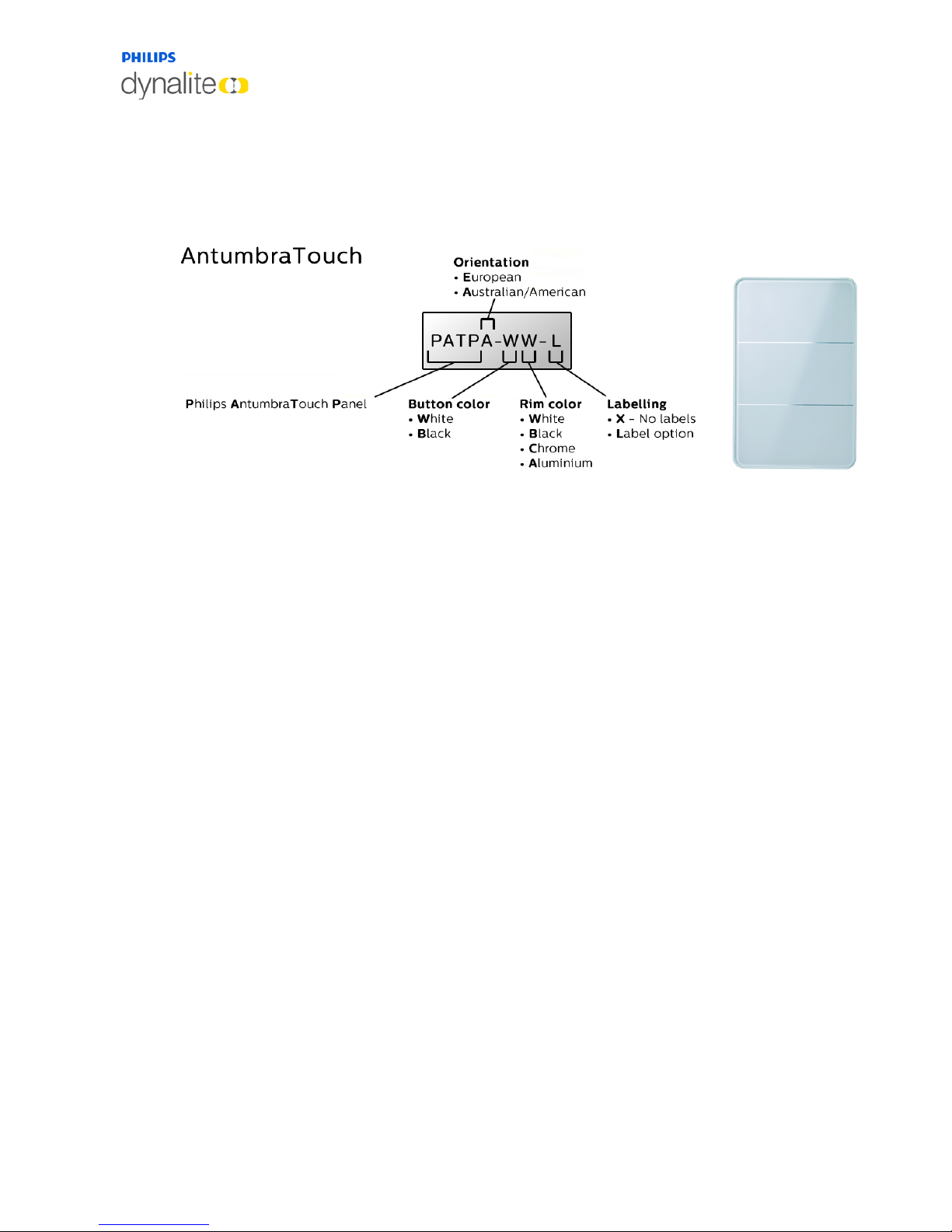
3.3 AntumbraTouch
This part number describes an Australian/American AntumbraTouch panel with white
buttons, white rim and labelled buttons.
Page 29

13 October, 2017
Antumbra 29 Ordering Antumbra Panels
3.3.1 Spare Parts
This table shows the part numbers for AntumbraTouch spare parts:
Product Type
Profile
Front
Rim Color
Custom
Part Number Code
Spare - Touch Glass Assembly
EU White White no PATSE-WW-X
Spare - Touch Glass Assembly
EU White White yes PATSE-WW-L
Spare - Touch Glass Assembly
EU White Chrome no PATSE-WC-X
Spare - Touch Glass Assembly
EU White Chrome yes PATSE-WC-L
Spare - Touch Glass Assembly
EU White Aluminum no PATSE-WA-X
Spare - Touch Glass Assembly
EU White Aluminum yes PATSE-WA-L
Spare - Touch Glass Assembly
EU White Black no PATSE-WB-X
Spare - Touch Glass Assembly
EU White Black yes PATSE-WB-L
Spare - Touch Glass Assembly
EU Black White no PATSE-BW-X
Spare - Touch Glass Assembly
EU Black White yes PATSE-BW-L
Spare - Touch Glass Assembly
EU Black Chrome no PATSE-BC-X
Spare - Touch Glass Assembly
EU Black Chrome yes PATSE-BC-L
Spare - Touch Glass Assembly
EU Black Aluminum no PATSE-BA-X
Spare - Touch Glass Assembly
EU Black Aluminum yes PATSE-BA-L
Spare - Touch Glass Assembly
EU Black Black no PATSE-BB-X
Spare - Touch Glass Assembly
EU Black Black yes PATSE-BB-L
Spare - Touch Glass Assembly
NA White White no PATSA-WW-X
Spare - Touch Glass Assembly
NA White White yes PATSA-WW-L
Spare - Touch Glass Assembly
NA White Chrome no PATSA-WC-X
Spare - Touch Glass Assembly
NA White Chrome yes PATSA-WC-L
Spare - Touch Glass Assembly
NA White Aluminum no PATSA-WA-X
Spare - Touch Glass Assembly
NA White Aluminum yes PATSA-WA-L
Spare - Touch Glass Assembly
NA White Black no PATSA-WB-X
Spare - Touch Glass Assembly
NA White Black yes PATSA-WB-L
Spare - Touch Glass Assembly
NA Black White no PATSA-BW-X
Spare - Touch Glass Assembly
NA Black White yes PATSA-BW-L
Spare - Touch Glass Assembly
NA Black Chrome no PATSA-BC-X
Spare - Touch Glass Assembly
NA Black Chrome yes PATSA-BC-L
Spare - Touch Glass Assembly
NA Black Aluminum no PATSA-BA-X
Spare - Touch Glass Assembly
NA Black Aluminum yes PATSA-BA-L
Spare - Touch Glass Assembly
NA Black Black no PATSA-BB-X
Spare - Touch Glass Assembly
NA Black Black yes PATSA-BB-L
Spare - Touch App Module Kit
EU N/A N/A N/A PATSE-AMK
Spare - Touch App Module Kit
NA N/A N/A N/A PATSA-AMK
Sales Demo Kit - TOUCH
EU N/A N/A N/A PATSE-DEMOPACK
Sales Demo Kit - TOUCH
NA N/A N/A N/A PATSA-DEMOPACK
Page 30

13 October, 2017
Antumbra 30 Ordering Antumbra Panels
Page 31

© 201
7 Koninklijke Philips Electronics N.V.
All rights reserved.
Philips International B.V.
The Netherlands
Document Revision: 01
 Loading...