

Philips an7384 DATASHEETS
ICs for Audio Common Use
■ Overview
The AN7384N is a volume control IC for recording level
adjustment of cassette deck and mini component stereo.
■ Features
•
High input dynamic range
•
Low output noise voltage
•
Capable of selecting two kinds of control mode
(1) L, R, independent volume
(2) Coalition volume + L, R balance
•
Reference voltage source for control voltage built-in
AN7384N
Electronic Volume IC for Cassette Deck
1
2
3
4
5
6
7
8
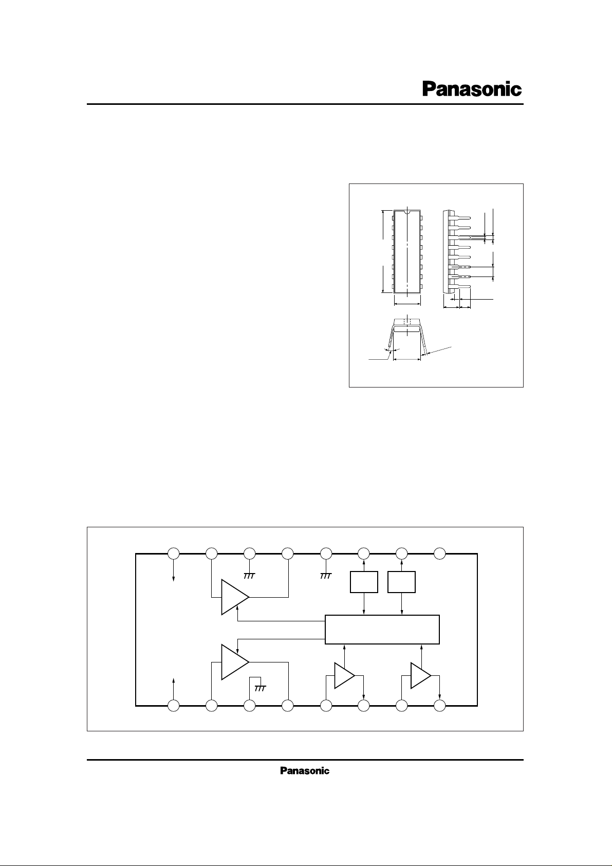
3.8±0.25 (3.45)
0.51min
2.54 1.2±0.25
0.5±0.1
Unit : mm
6.3±0.25
16
15
14
13
12
11
10
9
21.7±0.3
3 ~ 15˚
0.3
+ 0.1
– 0.05
7.62±0.25
16-Lead DIP Package (DIP016-P-0300E)
■ Block Diagram
V
EE
(SUB)
16 15 14 13 12 11 10 9
1 2 3 4 5 6 7 8
V
CC
GND3
VCA
VCA
GND1
GND2
V
REF
VCA Control
Buf. Buf.
Mode
SW.
NC
AN7384N
ICs for Audio Common Use
■ Absolute Maximum Ratings (Ta= 25˚C)
V
CC
I
CC
P
D
T
opr
T
stg
Supply Voltage
Supply Current
Power Dissipation
Operating Ambient Temperature
Storage Temperature
V
mA
mW
˚C
˚C
Parameter Symbol Rating Unit
±12
30
800
–20 ~ + 70
–55 ~ +150
±7V ~ ±11V
■ Recommended Operating Range (Ta = 25˚C)
Parameter Symbol Range
Operating Supply Voltage Range
V
CC
Positive Side Circuit Current
Negative Side Circuit Current
Attenuation – 1
Attenuation – 2
Channel Balance – 1
Distortion Rate – 1
Distortion Rate – 2
Noise Output Voltage – 1
Noise Output Voltage – 2
Channel Balance – 2
Max. Input Voltage
Max. Output Voltage
Control Voltage Range
Volume Mode Switching Voltage
Balance Mode Switching Voltage
Balance Mode Control Gain (Lch.)
Balance Mode Channel Balance
I
CC
I
EE
ATT – 1
*
1
ATT – 2
*
1
CB – 1
*
1
THD – 1
*
1
THD – 2
*
1
Vno – 1
*
1
Vno – 2
*
1
CB – 2
*
1
V
i (max.)
*
1
V
O (
max.)
*
1
V
cont
*
1
V
10 (V)
V
10 (B)
ATT
BG
CB – 3
Vin=
0dBV, Volume mode, V
cont
=
V
ref
Vin=
0dBV, Volume mode, V
cont
=
V
ref
Vin=
0dBV, Volume mode, V
cont
=
V
ref
Vin=
0dBV, Volume mode, V
cont
=
0V
V
in
=
0dBV, Volume mode, V
cont
=
V
ref
Vin=
–20dBV
, Volume mode,
V
cont
=
V
ref
Vin=
0dBV
, Volume mode, at
V
cont
=
–20dB
Without input (R
g
=
0Ω),
Volume mode
, V
cont
=
V
ref
, A
curve
Without input (R
g
=
0Ω),
Volume mode
, V
cont
=
0V, A
curve
Vin=
0dBV,
Volume mode
, at ATT= –20dB
THD= 3%, ATT= –20dB
THD= 3%, V
cont
= V
ref
Volume mode, Input –20dBV V
cont
to Pin5, V7=
0.5V
ref
Volume mode, Input –20dBV V
con
t
to Pin5, V7 =
0.5V
ref,
L/R
–20
–1
–2
–3
14.8
1.5
0
0
3.5
–22
–3
12
–9.1
0
–85
0
0.05
0.15
–106
0
16
–20
0
20
1
–80
2
0.1
0
–100
–110
3
V
ref
1.5
4.8
–18
3
mA
mA
dBV
dBV
dB
%
%
dBV
dBV
dB
dBV
dBV
V
V
V
dBV
dB
Parameter Symbol Condition min. typ. max. Unit
*
1 2-channel
*
2 Filter of 18dB/oct should be used at measurement.
*
2
*
2
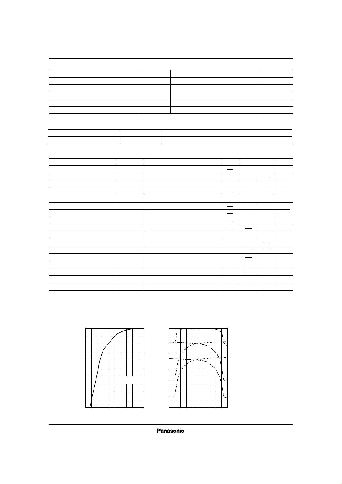
■ Electrical Characteristics (VCC = ±10V, Ta = 25˚C)
Independent Volume Mode Attenuation Characteristics
0
– 20
– 40
– 60
– 80
V
cont
(V)
Attenuation (dB)
20 1 543
V
in
= 0dB 1kHz
Balance Mode Attenuation Characteristics
0
– 10
– 20
– 30
– 40
– 50
– 60
– 70
– 80
– 90
Pinu V (V)
Attenuation (dB)
20 1 543
VIN= 0dBV
f= 1kHz
V
cont.1
SLO
(Without Enter)
V
Out
= 0dBV
V
Out
= – 40dBV
V
Out
= – 20dBV
V
REF
■ Characteristics Curve
 Loading...