

Page 1
Wall Mount Split Units
AMW/AMC 25, 30, 45 &60
by AITONS'
AMW / AMC SERIES
Installation, Operation
And Maintenance Manual
Please read this manual before
installing and operating the unit
CONTENTS
INSTALLATION INSTRUCTIONS
! Tools / Supplies
! Safety considerations
! Selection of location
! Recommended height and length
! Installation Method
! Refrigerant piping & drainage
! Electrical wiring
OPERATING INSTRUCTIONS
! Operating tips
! Product description
! Auxiliary control
! Remote control operation
! Operating instructions
! Care and maintenance
! Trouble shooting
Page 2

INSTALLATION INSTRUCTIONS
TOOLS AND SUPPLIES
The following tools are needed
for installation.
1. Level
2. Hole Saw
3. Core bits
4. Hammer
5. Drill
6. Torque wrench
7. Adjustable wrench
8. Flat head screwdriver
9. Philips head screwdriver
10. Wire stripper
11. Measuring tape
12. Ratchet set
13. Flaring tools
14. Tube cutter
The following materials are
required:
1. Correct size copper tubing
2. Correct size drain pipe
3. Sleeve and bush
4. Vinyl tape
5. Saddle & Clamps to support
refrigerant piping
6. Power supply cable
7. Insulation material
8. Putty or similar sealant
SAFETY CONSIDERATIONS
Installation and servicing of air conditioner can be hazardous due to high refrigerant pressure
and electrical components inside the unit. Only fully trained, qualified and certified service
personnel should install, repair and service the air conditioner.
While working on the air conditioner, all precautions in the literature, tags and labels attached to
the unit and all other general safety precautions should be carefully observed. Please follow all
safety codes, wear safety glasses and work gloves. Also use quenching cloth for brazing
operations.
It is highly recommended that this manual be read completely before installing and operating the
system.
WARNING: The main power breakers to the unit , including its accessory or
parts, should be turned off before performing service or maintenance operations
on the unit. Dangerous high voltage can cause electric shock, serious personal
injury or even death.
Page 3
SELECTION OF LOCATION
Select a convenient location where:
INDOOR UNIT
! The cool air can reach every corner of the
area to be cooled.
! The unit is away from any direct heat
source
! Easy and short routing of the refrigerant
and drain pipes to the exterior.
! There are no flammable gas, alkaline or
acid present in the air.
! Air circulation is not obstructed, preventing
good air circulation.
! The structure where the unit is installed
should be strong enough to support the
weight of the unit and also prevent any
vibration during operation of the unit.
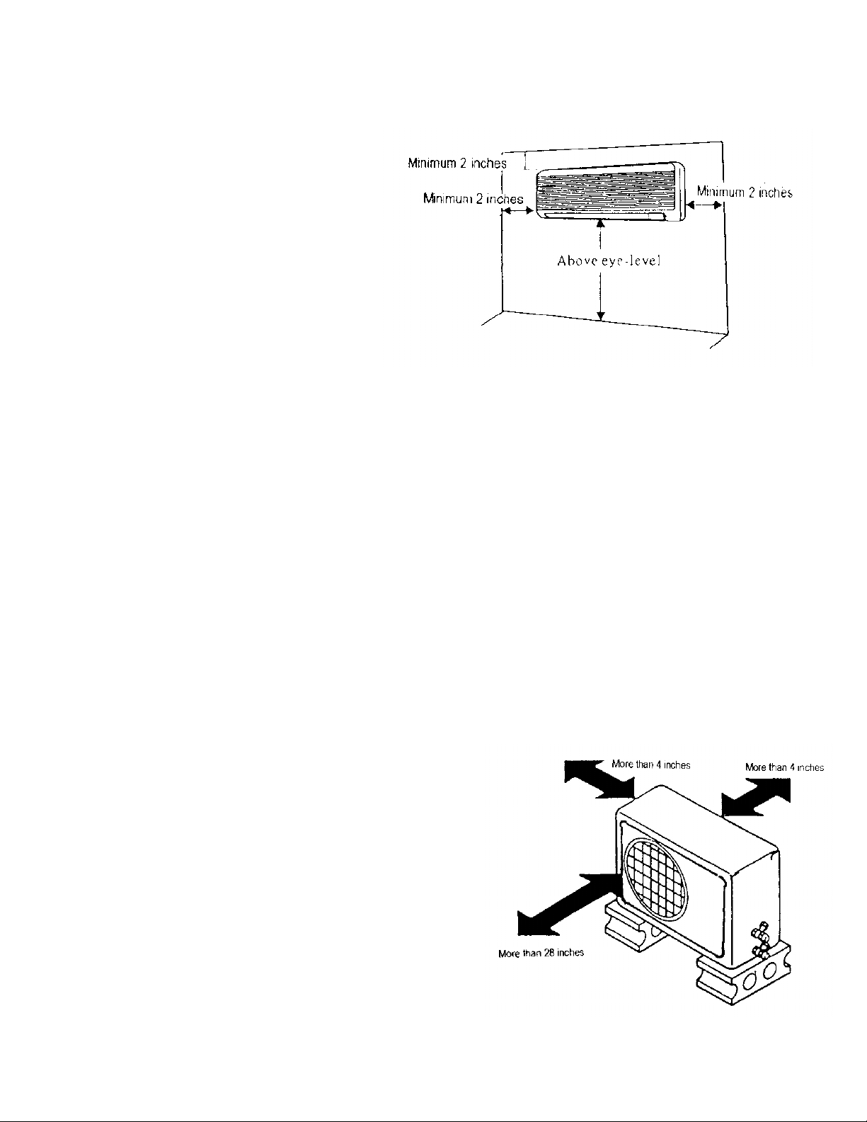
! Figure on the right shows the spacing to the
nearest wall.
OUTDOOR UNIT:
! The condensing unit should be located as
close as possible to the fan coil.
! The air inlet shall be located at least 4” from
the wall or other obstruction for unrestricted
airflow.
! The air outlet shall be located so as to
direct discharged warm air away from the
building. (Avoid low overhanging roofs to
avoid re-circulation of condenser discharge
air on vertical discharge models.)
! Mount the unit on a sturdy base.
! Figure on the right shows the spacing to be
provided.
Page 4
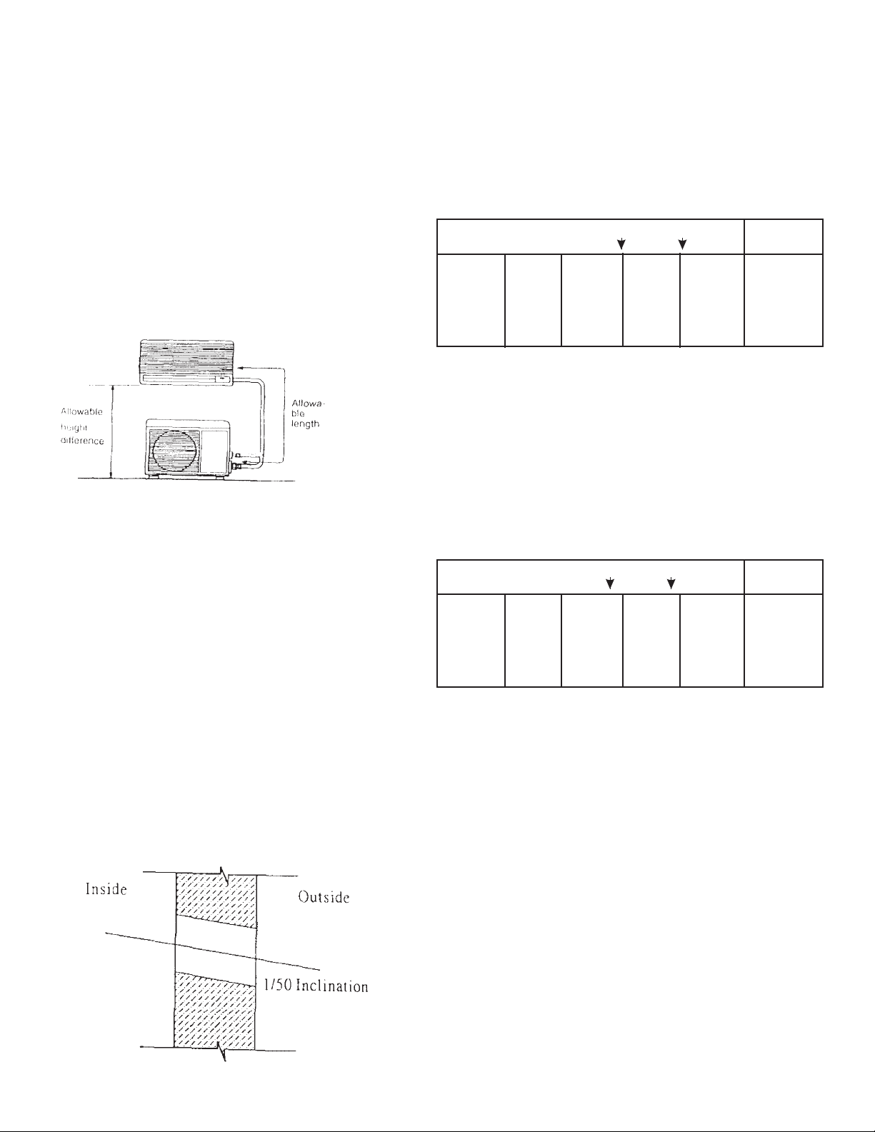
RECOMMENDED HEIGHT AND LENGTH
If the refrigerant piping is longer than the
recommended length, or if the height
difference between the indoor and outdoor
unit is greater than recommended, the
capacity will drop and the compressor could
malfunction. Select an installation location
that is within the recommended parameters.
Cooling
capacity
7,500 to
9,000
Btuh
Recommended height difference is 23 ft or less
*Evacuate refrigerant lines
An installation with a piping length of 23 ft. or less is desirable.
(1)
If this is not possible, the maximum piping length can be
extended to 50 ft. by charging the system with additional
refrigerant. However, cooling and heating capacity will be
reduced.
• Additional charge volume = (piping length - 23 ft.) x 0.2 oz.
& HEIGHT RECOMMENDED)
Add
charge
(MAXIMUM PIPING LENGTH
Piping length (feet)
Not
needed
23 50
Installation
Needed
(1)
not
recom-
mended
Notes
Unit
Piping
Diameter
1/4" and
3/8”
INSTALLATION METHOD
HOLE DRILLING: After deciding the
method your unit will be installed, a hole to
route the connecting tubes and wires to the
outdoor unit is to be drilled on the wall. The
hole must be lower than the point where the
drainpipe attaches to the drain pan of the
unit. It should also be slightly declined
towards the outside.
Piping length (feet)
Cooling
capacity
18,500 to
36,000
Btuh
Recommended height difference is 23 ft or less
*Evacuate refrigerant lines
An installation with a piping length of 33 ft. or less is desirable.
(2)
If this is not possible, the maximum piping length can be
extended to 55 ft. by charging the system with additional
refrigerant. However, cooling and heating capacity will be
reduced.
• Additional charge volume = (piping length - 33 ft.) x 0.2 oz.
Add
charge
needed
Not
33 55
Needed
(2)
Installation
not
recom-
mended
Notes
Unit
Piping
Diameter
Page 5
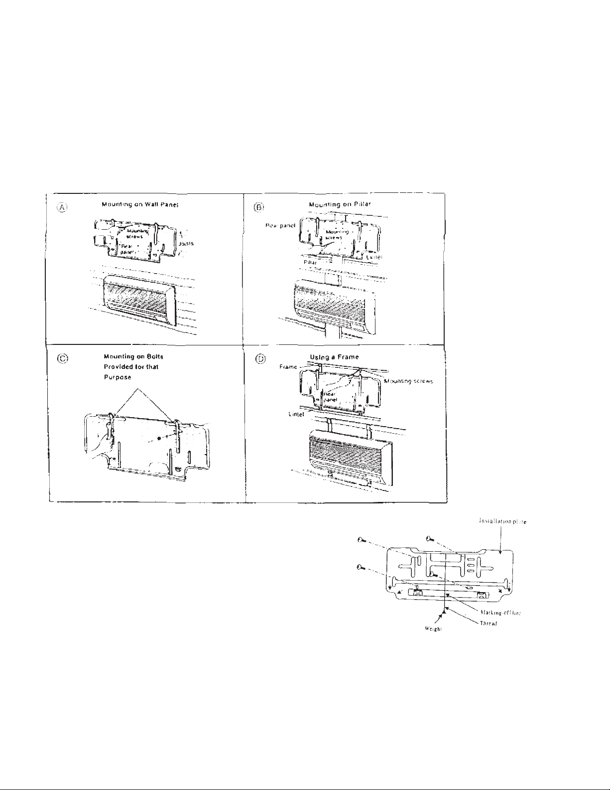
MOUNTING INSTALLATION PLATE:
The fan coil can be installed using any of the four methods described below.
Determine which is the most suitable method.
Position the installation plate on the wall
making sure that it is parallel to the ground.
This can be done by aligning the markingoff line with a thread and weight as shown
in figure on the right. This is to ensure that
the condensate water does not overflow
from the drain pan.
Mount the installation plate with the 4
screws provided. (If the unit is to be
mounted on a concrete wall, consider using
anchor bolts instead of the screws provided.
Page 6
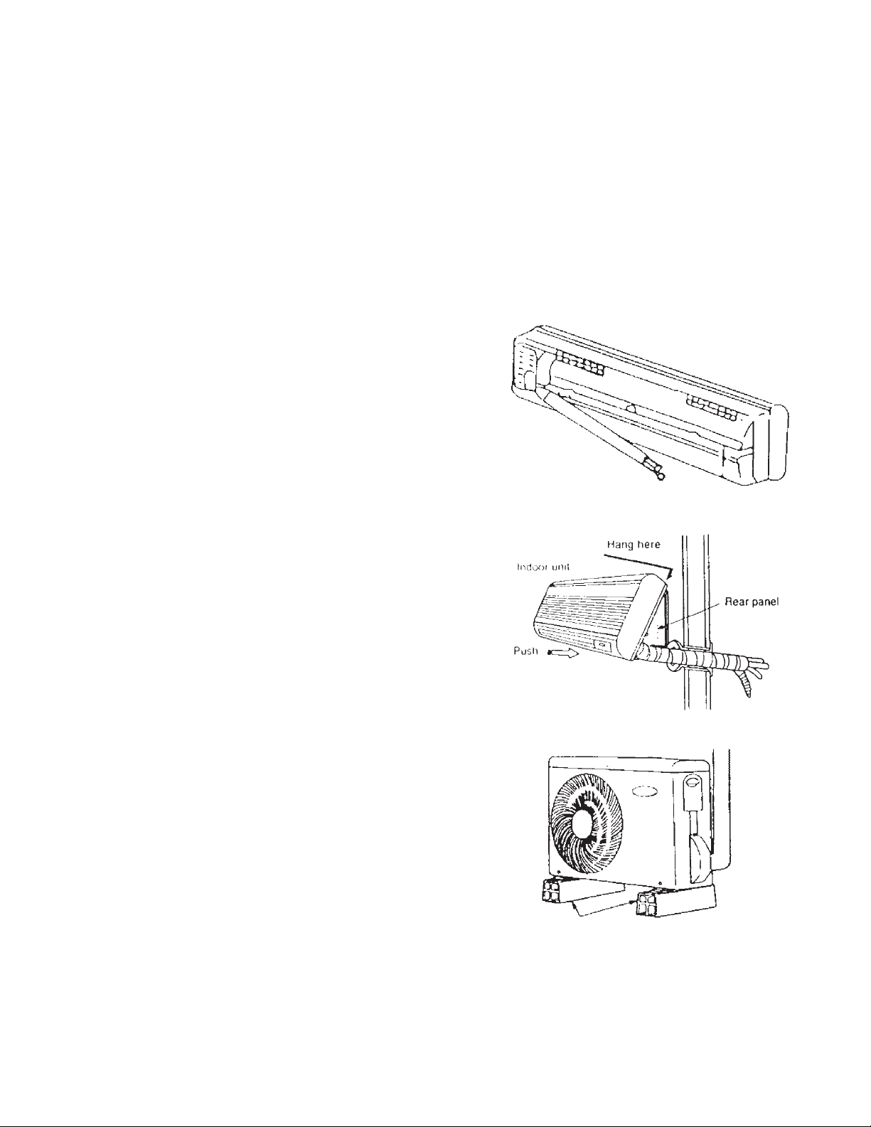
INSTALLATION OF FAN COIL:
The extended liquid and suction pipes and drain hose are hidden inside a slot at the
back of the fan coil. This allows the hole on the wall to be either on the right or left side
of the fan coil.
RIGHT SIDE HOLE POSITION: The piping and drain hose are routed straight through
the hole.
LEFT SIDE HOLE POSITION: The
piping and drain hose run from the
right side to the left side of the unit,
hidden in the slot at the back of the
unit before routing through the hole
on the left side of the unit.
MOUNTING FAN COIL UNIT:
Hook the fan coil onto the upper
portion of the installation plate
ensuring that it sits securely on the
installation plate.
Press the lower portion of the unit
against the installation plate until the
hooks at the back of the unit are
securely engaged with the installation
plate.
MOUNTING CONDENSING UNIT:
Do not place the condensing unit
directly on the ground. It should
preferably be placed on a slightly
raised platform to prevent rain water
from splashing into it. Also ensure
that it is level. Avoid installing the unit
in places where flammable gases
may be present.
beams or blocks
If necessary, due to the placement conditions,
rubber cushions can be placed underneath the
outdoor unit.
Page 7

REFRIGERATION PIPING & DRAINAGE
PREPARATION OF PIPING
Fan coil and side discharge condensing units are equipped with flare connections. Improper flaring
and brazing may cause refrigerant to leak out of the system. Follow these instructions carefully in
preparing the refrigerant piping.
! Ensure that all piping is of the correct size.
! Measure the distance between the indoor and outdoor units' refrigerant connections, together
with all the curves necessary. Add a few inches as slack.
! Lay the piping as straight as possible on a flat surface and with a pipe cutter, cut the piping
according to the measured length.; Do not tighten the cutter excessively during cutting as this
may cause the pipe to deform. Do not use hacksaw or similar tools to cut the pipe, as it results
in metal shavings getting inside the pipe. This also makes proper flaring impossible.
! Use a reamer to remove burrs from cut edges. Hold the pipe ends upside down to prevent
metal powder from getting into the pipe.
Pipe
Reamer
Note:
As the pipe is round, cutting should be
performed on a straight section. Also,
do not apply too much force with the
blade of the pipe cutter.
Pipe cutter
Keep pipe facing downward
when removing burrs.
! For connection to flare settings, the pipe has to be flared. Remove the flare nut from the unit
and insert it onto the piping.
! Fit the pipe into the bar of the flare tool, about 0.5 mm higher than the surface of the bar.
! Center the flare punch carefully on the pipe and turn gradually to widen the pipe. Check the
finish of the flare to ensure even flaring.
! Cover the flared ends with tape to prevent dust from entering.
Handle
Flaring tool
Flaring bar
Length of periphery portion
Flare nut
L should be constant
0.635 (1/4”) only 0.952 (3/8”) and larger
Approx. 1 mm
0.5 mm
Page 8
PIPING INSULATION
Liquid and suction lines must be insulated
separately. In a cooling only type air
conditioner, both pipes become cold during
operation. This can cause moisture to
condense on the surface of the pipes,
resulting in heat loss.
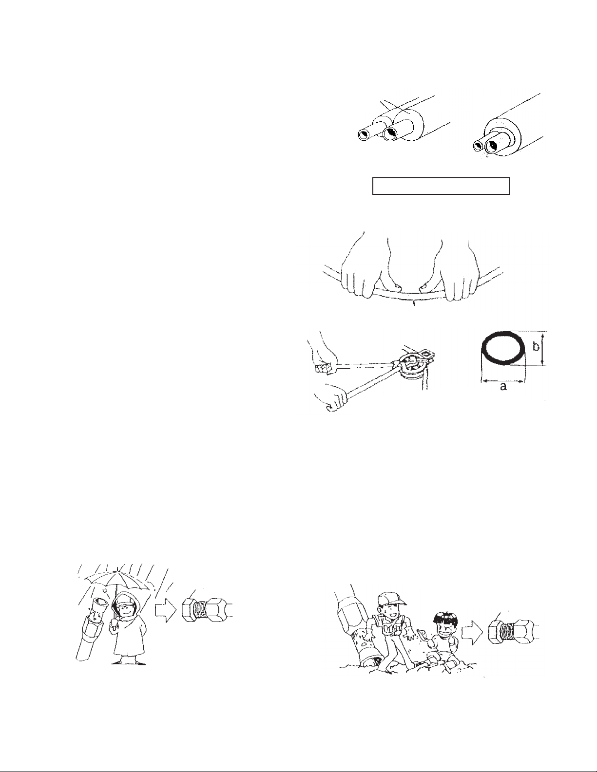
PRECAUTIONS WHEN BENDING
PIPES
! The air conditioner's performance
will suffer if the piping is crushed.
! Bend pipes using the pads of your
thumbs to prevent them from
collapsing (See picture on the right.)
! Use a pipe bending tool to bend pipe
wider than 1/2" in diameter.
Insulation
Narrow Pipe
Bend with pads of thumbs
Wide Pipe
Common insulation
Separate insulation is essential
Pipe bending tool
FLARE FITTING CONNECTION. There are 3 piping rules:
(a) DRY: Never allow any water to get
inside the piping.
Cap
Keep cap attached until immediately
before making piping connections.
(b) CLEAN: Never allow dirt, sand or other
foreign particles to get inside the piping.
b/a = 0.7 or more
Cap
Keep cap attached until immediately
before making piping connections.
Page 9

(c) PRECAUTIONS WHEN CONNECTING PIPES:
Connections will go more smoothly if the
large pipe is connected first, followed by the
small pipe. Hold the nipple and the flare
nut straight and lightly turn the nut two or
three turns by hand to ensure that the
threads are aligned.
Then tighten to the specified torque using a
wrench. In particular, when tightening 1/4"
diameter flare nuts, use the specified torque
wrench
Fan Coil
! Align the center of both flare fittings
and tighten the flare nut with your
hand.
! With a torque wrench tighten the
flare nut fully.
Torque wrench
First, 2 or 3 turns by hand
Nipple
Flair nut
Fix in place.
Wrench
Torque wrench
Always look at arrow on
torque wrench to
determine direction.
Condensing Units
! Align the center of the flare nut of the
liquid line to the liquid valve. Tighten
the flare nut, first with your hand and
then fully tighten with the torque
wrench.
! Align the center of the flare nut of the
gas line to the gas valve. Tighten
the flare nut with your hand. After
purging, tighten it fully with a torque
wrench and check all connections for
leaks with soap solution.
Outdoor unit
Liquid side piping
Gas side piping
Torque wrench
Page 10

AIR PURGING
This procedure is used to remove air from inside the piping connecting the indoor and outdoor units,
as well as the air inside the indoor unit. If air purging is not carried out, air will beocme mixed into the
refrigerant cycle, causing the pressure to rise to abnormally high levels, increasing power
consumption and reducing the capacity of the unit. Also, moisture in the air can cause insulation
failure in the compressor motor and deterioration of the refrigerant oil, resulting in a significant
reduction in the air conditioner life.
The procedure is as follows:
! Confirm that all piping connections
have been completed correctly.
! Connect a gauge manifold and a
vacuum pump as shown in the
diagram.
! Completely open the low-pressure
valve of the gauge manifold and
completely close the high-pressure
valve.
! Start the vacuum pump and allow it
to operate until the pressure is at 29”
of vacuum. This will take about 15
minutes or more.
! With the low-pressure valve
completely open, switch off the
vacuum pump.
! Completely open both the suction
and liquid service valves.
! Disconnect the manifold.
! Tighten the caps on the service
valves and the flange nut on the
charging port.
Narrow pipe
service valve
Wide pipe
service valve
Low pressure
valve
Gauge Manifold
High pressure
valve
Vacuum pump
Page 11

DRAIN PIPE CONNECTION
The fan coil is equipped with a drain hose. It is
tied together with the refrigerant piping. During
installation, it is important to observe the following
instructions to prevent water overflowing from the
drain pan.
! Insure that the indoor unit is level and not
tilted forwards or backwards.
! Insure that the drain hose does not rise
above the drain pan. It should be sloping
towards the hole.
! Route the drain hose through the same
hole as the refrigerant pipes.
! If the drain pipe extends horizontally a long
way, use PVC tubing to provide heat
insulation.
! Outside insert the drain hose into a PVC
drainpipe and not the other way around and
glue them together.
! Run the PVC drainpipe straight down the
wall. There should be no traps and avoid
putting the end of the pipe into water.
! Ensure that all sections of the PVC pipes
are glued securely together.
! Ensure that the entire indoor part of the
drain hose is insulated to avoid
condensation from dripping.
! Drain pipe may be required for heat pump
unit and should be connected if necessary.
Drain Pipe
• Traps
Trap
• Long Horizontal Extensions
Good
No good
The lack of a
downward
slope causes
water to build
up and
overflow the
drain pan.
Even if there is a downward slope overall,
there must not be any “double traps” formed
Gap of approximately 50 cm
Secure in place
with saddles
Good
Drain hose
Downward
Slant
Down-
ward
slant
Drain Pipe
Traps
Stiff vinyl
chloride (PVC)
tubing
Trap effect created
Flexible tube
No good
Drain water cannot
flow freely
Drainage gutterDrainage gutter
SLIME
Water leakage due to a clogged drain hose can be caused by accumulated dirt in the drain pan or by
a buildup of slime inside the drain hose.
Slime is caused by the following factors:
! Temperature : 25°C (77°F) to 30°C(86°F)
! Accumulated water
! Nutrients (components of perspiration and dust in the air)
! A combination of certain types of mold and bacteria.
To reduce the chance of clogging, it is very important to ensure that the drain hose has a downward
slant to prevent water from accumulating and a clean and a well ventilated environment.
Page 12

Outdoor unit
Holder for
connecting cable
Control board
cover
ELECTRICAL WIRING
to power supply
LOCATION OF TERMINAL BLOCK:
The terminal block on the indoor unit is located
next to the PCB. Cable access is through the
back of the unit. For the condensing unit, the
terminal block is located behind the control panel.
Holder to
power supply cord
connecting cable
WIRING CONNECTION:
! All wiring and grounding must comply with the local Electric Codes.
! See the unit nameplate for electrical rating and use correct wire size to handle the minimum
circuit ampacity required for the unit. Refer to Local Electric Codes for wire sizing.
! Always use a separate power line with circuit breaker for each air conditioner.
! Always ground the unit.
! Ensure that no wiring touches the tubing, motors or any other moving parts.
! Depending on the outdoor unit type, the number of inter-connecting wires between indoor and
outdoor unit varies. Please refer to the wiring diagram on the unit to determine the number of
wires required and correct connection.
! Finally inspect all the electrical connections, including the factory wiring to ensure that all
connections are tight.
EXTERNAL FINISHING OF PIPING
! After completing the installation of the
refrigerant piping, drain pipe and wiring,
bind them together into a bundle with tape
at 4 inches to 8 inches (100 to 200 mm)
intervals. Start from the bottom and work to
the top. Keep the drainpipe at the bottom
of the bundle.
! Do not fail to apply insulation to the joints
and wrap them with tape. If the joints are
not insulated, condensation could form on
them, resulting in water leakage.
! Use saddles to secure piping in place so
that it does not sway back and forth.
! Plug any open portions of the pass through
hole with putty to ensure that no rain or
wind can get inside.
! Finally, tidy up both the inside and outside
and the installation process is complete.
Insulation
Refrigerant Tubing
Wall cap
Putty
Inside
Putty
Inter-connecting Wiring
Insulation
Wall
Outside
Tape
Drain Pipe
Putty
Page 13

OPERATING INSTRUCTIONS
OPERATING TIPS:
Observe the following points for economical and safe operation:
! Keep the room temperature at a comfortable level. Too much cooling is unhealthy and results
in excessive consumption of electricity. A temperature setting of 75°F (24°C) is usually
sufficient during the day. During the night, set the temperature a few degrees higher as the
body temperature is reduced when a person is asleep.
! Adjust the vertical and horizontal louvers to provide uniform distribution of air in the room.
! Clean the filter at least twice a month. A clogged air filter reduces performance and increases
power consumption.
! Keep the indoor and outdoor coils clean to maintain high heat transfer capability. Periodically,
inspect the coils and call a professional serviceman to clean the coils with special cleaning
chemicals if necessary.
! Reduce heat gain through windows by stopping direct sunlight with curtains or blinds. Awnings
are also helpful by creating shade around the windows. Keep windows and doors closed
except when ventilating the room.
! It is good practice to ventilate the room occasionally to rid the room of stale air.
PRODUCT DESCRIPTION
Figure below illustrates the important components of the air conditioning unit.
Front Cover
Auxiliary controller
Indicating lamps
Vertical louver
Horizontal louver
Remote controller
Air filter
Pipe and electrical
Drain hose
Page 14

AUXILIARY CONTROL
Figure below illustrates the auxiliary control on the fan coil. This can be used to
operate / control the air conditioner when the remote controller is not available or lost.
Test
Use to operate the air conditioner under "COOL" mode. All other functions will not be
effective. The air conditioner will automatically stop operating after 30 minutes. This is
to test if the air conditioner is in working condition.
Remote
In this position, the air conditioner is controlled by the remote controller.
Auto
Use to by-pass the remote controller. The air conditioner will operate automatically
when power is supplied. The remote controller is ineffective in this position.
Red indicating lamp
Red light will be lit when electrical power is supplied to the air conditioner.
Green indicating lamp
This green lamp will be lit when the compressor starts operating. It indicates cooling
operation is in progress. It will blink if the operating temperature is abnormal.
Page 15

REMOTE CONTROL OPERATION
CONTROLS AND INDICATORS
Figure below illustrates the various controls and indicators of the LCD wireless remote
control.
MODEL: AMW 25, 30
Page 16

MODEL: AMW 45, 60
Page 17

OPERATING INSTRUCTIONS
Before operating the unit for the first time, it is necessary to install the batteries in the
remote controller.
! Batteries are located at the back of the
remote controller (Model AMW25, 30) and
at the front of the remote controller (Model
AMW45, 60).
! Open the battery holder by simultaneously
pushing downwards and inwards at the
area marked "OPEN"
! Use only "AAA" alkaline batteries
! Dispose of used batteries correctly, in a
manner not causing pollution or harm to the
environment.
OPERATING GUIDE MODEL: AMW 25, 30
! Start air conditioner. Point the remote controller at the fan coil and press ON/OFF button.
! Select the operational mode. Press either "Cool", "Dry" or "Vent" button to select the desired
mode.
! Set temperature. Press "+" or "-" button to set desired temperature.
! Select fan speed. Press "Fan" button to select desired fan speed.
! Set airflow position. Press "Vane" button to adjust airflow direction or to set vane to auto
swing.
! Set Timer. If required, press "Time" button to set timer On or Off. After pressing "Time"
button, the Time display on the LCD will start to flash. Press "+" or "-" to set the time before
flashing stops.
! Sleep mode. Select sleep mode by pressing "Time:" button until "Sleep" appears on the LCD
display. Sleep mode allows the air conditioner to raise the room temperature by up to 2°F from
set temperature while you sleep to save power.
Page 18

MODEL: AMW 45, 60
! Start air conditioner. Point the remote controller at the fan coil and press "ON/OFF" button.
! Select operation mode. Press "Mode" button to select any of the following modes: "Cool",
"Dry" or "Vent".
! Temperature setting. Press "+" or "-" button to set desired temperature.
! Select fan speed. Press "Fan control" button to select desired fan speed.
! Select airflow direction. Press "Louver control" button to set position of horizontal vane or
set it to auto swing.
! Set Timer. If desired, set timer on or off by pressing "Time Control" button, followed by "+" or
"-" button to select time before air conditioner starts or stops operating.
! Sleep mode. Press "Sleep" button to select sleep mode. A s the name suggests, it is used
during sleeping. The room temperature would be adjusted by 2°F up from set temperature to
save power.
2) FUNCTIONS
AUTO
This allows the air conditioner to operate automatically at a pre-set temperature. Cooling will be
affected when room temperature is above 82°F (28°C).
COOLING
When activated, the fan will automatically operate at high speed for 5 minutes before operating at the
set speed. During cooling if the humidity in the room is very high (RH above 80 %), condensation
may occur at the air discharge louver. It is advisable to operate the fan at high speed under this
condition.
DRYING
When activated, the air conditioner will operate on and off intermittently. The fan will automatically
operate at low speed. Fan speed, temperature settings and sleep mode will be by-passed. This
function will not operate if the room temperature is lower than 59°F (15°C).
FAN ONLY
The following speed can be selected. Low mid high auto. At auto, the fan speed will be
automatically selected by the micro-processor, depending on the difference between factory pre-set
and room temperature.
TIMER
This feature allows the air conditioner to be automatically SWITCH ON or SWITCH OFF after a predetermined time.
CLOCK
This is for setting the real time to facilitate the operation of the timer.
Page 19

CARE AND MAINTENANCE
! The air conditioner requires proper care and maintenance for efficient operation.
A periodic inspection and cleaning may be available from your dealer or
distributor. Be sure to ask about this service at the time of installation. The user
can also perform some of the care and maintenance. Please follow these
instructions.
! Be sure to disconnect the power supply before undertaking any inspection.
! Open the RETURN AIR GRILLE and remove the air filters. Clean by washing or
with a vacuum cleaner. Dry the filters before putting them back on the unit.
! Do not operate the air conditioner without the air filters in it. Remember that the
filters protect the coil from getting dirty. A dirty coil is more difficult to clean than a
dirty filter. Clean the filters at least twice a month and more if the environment is
dusty.
! CLEAN THE UNIT: Clean with a wet soft cloth. Do not wash the air conditioner.
Never use the following to clean the air conditioner.
• Hot water above 104°F (40°C).
• Volatile substances like benzene, gasoline, thinner and other solvents.
END OF SEASON:
! When the air conditioner is to stop operating for prolonged periods, for example,
at the end of the season, please follow these instructions before shut down.
Operate the unit at the following setting for 2 to 3 hours.
• Type of Operation: Cool
• Temperature setting: 86°F (30°C).
• This will dry up any residual water in the unit.
• Remove the batteries from the Remote Controller.
! Use car wax on the painted surface of the outdoor unit.
START UP: Operation after prolonged period
! Clean the unit and the filter as described above.
! Operate the FAN ONLY for half a day to remove any moisture that may have
accumulated inside the unit.
Page 20

TROUBLE SHOOTING
The following are normal and should not be treated as defects.
! Hissing sound, like flow of water from the unit. This is the sound of the
refrigerant at the expansion device, which can be heard from time to time
depending on the indoor and outdoor ambient conditions.
! The unit does not cool for a few minutes after it restarts. This is because a time
delay mechanism built into the unit prevents the compressor from starting for a
few minutes. This is to protect the compressor from breakdown.
! Smell from the supply air: The coil and filters absorb the smell from the
environment and the supply air may also have the same smell. This usually
happens in places where heavy cigarette smoke exists in the air.
BEFORE CALLING FOR SERVICE, PLEASE CHECK THE FOLLOWING:
Air conditioner does not operate:
! Check the thermostat setting to ensure that it is not set above the room
temperature.
! Check the circuit breaker.
! Check the power supply to ensure that it is not interrupted.
Cooling is insufficient:
! Check and clean the filters if necessary.
! Check that the thermostat setting is not above room temperature for cooling.
! Check that all windows and doors are closed.
! Check if there are sources of heat present in the room, like stove burners.
! Check that the fan speed is set to the HIGH setting
! If the system still does not operate or does not provide sufficient cooling, call for
a professional serviceman.
Page 21

AMW/AMC 25
Page 22

AMW/AMC 30
Page 23

AMW/AMC 45 & 60
Page 24

SERVICE NOTES
AITONS' EQUIPMENT INC.
Guelph, Ontario
www.aitons.com
e-mail: info@aitons.com
Printed in Canada 03/03
 Loading...