

Philips AMC S, AMC 25, AMC 30, AMW, AMC 45 User Manual
...
Wall Mount Split Units
AMW/AMC 25, 30, 45 &60
by AITONS'
AMW / AMC SERIES
Installation, Operation
And Maintenance Manual
Please read this manual before
installing and operating the unit
CONTENTS
INSTALLATION INSTRUCTIONS
! Tools / Supplies
! Safety considerations
! Selection of location
! Recommended height and length
! Installation Method
! Refrigerant piping & drainage
! Electrical wiring
OPERATING INSTRUCTIONS
! Operating tips
! Product description
! Auxiliary control
! Remote control operation
! Operating instructions
! Care and maintenance
! Trouble shooting

INSTALLATION INSTRUCTIONS
TOOLS AND SUPPLIES
The following tools are needed
for installation.
1. Level
2. Hole Saw
3. Core bits
4. Hammer
5. Drill
6. Torque wrench
7. Adjustable wrench
8. Flat head screwdriver
9. Philips head screwdriver
10. Wire stripper
11. Measuring tape
12. Ratchet set
13. Flaring tools
14. Tube cutter
The following materials are
required:
1. Correct size copper tubing
2. Correct size drain pipe
3. Sleeve and bush
4. Vinyl tape
5. Saddle & Clamps to support
refrigerant piping
6. Power supply cable
7. Insulation material
8. Putty or similar sealant
SAFETY CONSIDERATIONS
Installation and servicing of air conditioner can be hazardous due to high refrigerant pressure
and electrical components inside the unit. Only fully trained, qualified and certified service
personnel should install, repair and service the air conditioner.
While working on the air conditioner, all precautions in the literature, tags and labels attached to
the unit and all other general safety precautions should be carefully observed. Please follow all
safety codes, wear safety glasses and work gloves. Also use quenching cloth for brazing
operations.
It is highly recommended that this manual be read completely before installing and operating the
system.
WARNING: The main power breakers to the unit , including its accessory or
parts, should be turned off before performing service or maintenance operations
on the unit. Dangerous high voltage can cause electric shock, serious personal
injury or even death.
SELECTION OF LOCATION
Select a convenient location where:
INDOOR UNIT
! The cool air can reach every corner of the
area to be cooled.
! The unit is away from any direct heat
source
! Easy and short routing of the refrigerant
and drain pipes to the exterior.
! There are no flammable gas, alkaline or
acid present in the air.
! Air circulation is not obstructed, preventing
good air circulation.
! The structure where the unit is installed
should be strong enough to support the
weight of the unit and also prevent any
vibration during operation of the unit.
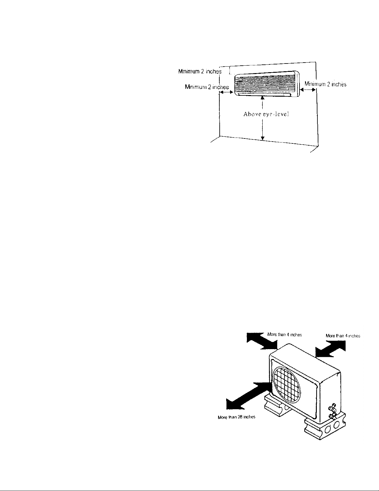
! Figure on the right shows the spacing to the
nearest wall.
OUTDOOR UNIT:
! The condensing unit should be located as
close as possible to the fan coil.
! The air inlet shall be located at least 4” from
the wall or other obstruction for unrestricted
airflow.
! The air outlet shall be located so as to
direct discharged warm air away from the
building. (Avoid low overhanging roofs to
avoid re-circulation of condenser discharge
air on vertical discharge models.)
! Mount the unit on a sturdy base.
! Figure on the right shows the spacing to be
provided.
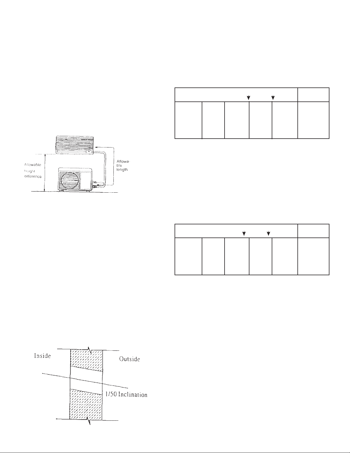
RECOMMENDED HEIGHT AND LENGTH
If the refrigerant piping is longer than the
recommended length, or if the height
difference between the indoor and outdoor
unit is greater than recommended, the
capacity will drop and the compressor could
malfunction. Select an installation location
that is within the recommended parameters.
Cooling
capacity
7,500 to
9,000
Btuh
Recommended height difference is 23 ft or less
*Evacuate refrigerant lines
An installation with a piping length of 23 ft. or less is desirable.
(1)
If this is not possible, the maximum piping length can be
extended to 50 ft. by charging the system with additional
refrigerant. However, cooling and heating capacity will be
reduced.
• Additional charge volume = (piping length - 23 ft.) x 0.2 oz.
& HEIGHT RECOMMENDED)
Add
charge
(MAXIMUM PIPING LENGTH
Piping length (feet)
Not
needed
23 50
Installation
Needed
(1)
not
recom-
mended
Notes
Unit
Piping
Diameter
1/4" and
3/8”
INSTALLATION METHOD
HOLE DRILLING: After deciding the
method your unit will be installed, a hole to
route the connecting tubes and wires to the
outdoor unit is to be drilled on the wall. The
hole must be lower than the point where the
drainpipe attaches to the drain pan of the
unit. It should also be slightly declined
towards the outside.
Piping length (feet)
Cooling
capacity
18,500 to
36,000
Btuh
Recommended height difference is 23 ft or less
*Evacuate refrigerant lines
An installation with a piping length of 33 ft. or less is desirable.
(2)
If this is not possible, the maximum piping length can be
extended to 55 ft. by charging the system with additional
refrigerant. However, cooling and heating capacity will be
reduced.
• Additional charge volume = (piping length - 33 ft.) x 0.2 oz.
Add
charge
needed
Not
33 55
Needed
(2)
Installation
not
recom-
mended
Notes
Unit
Piping
Diameter
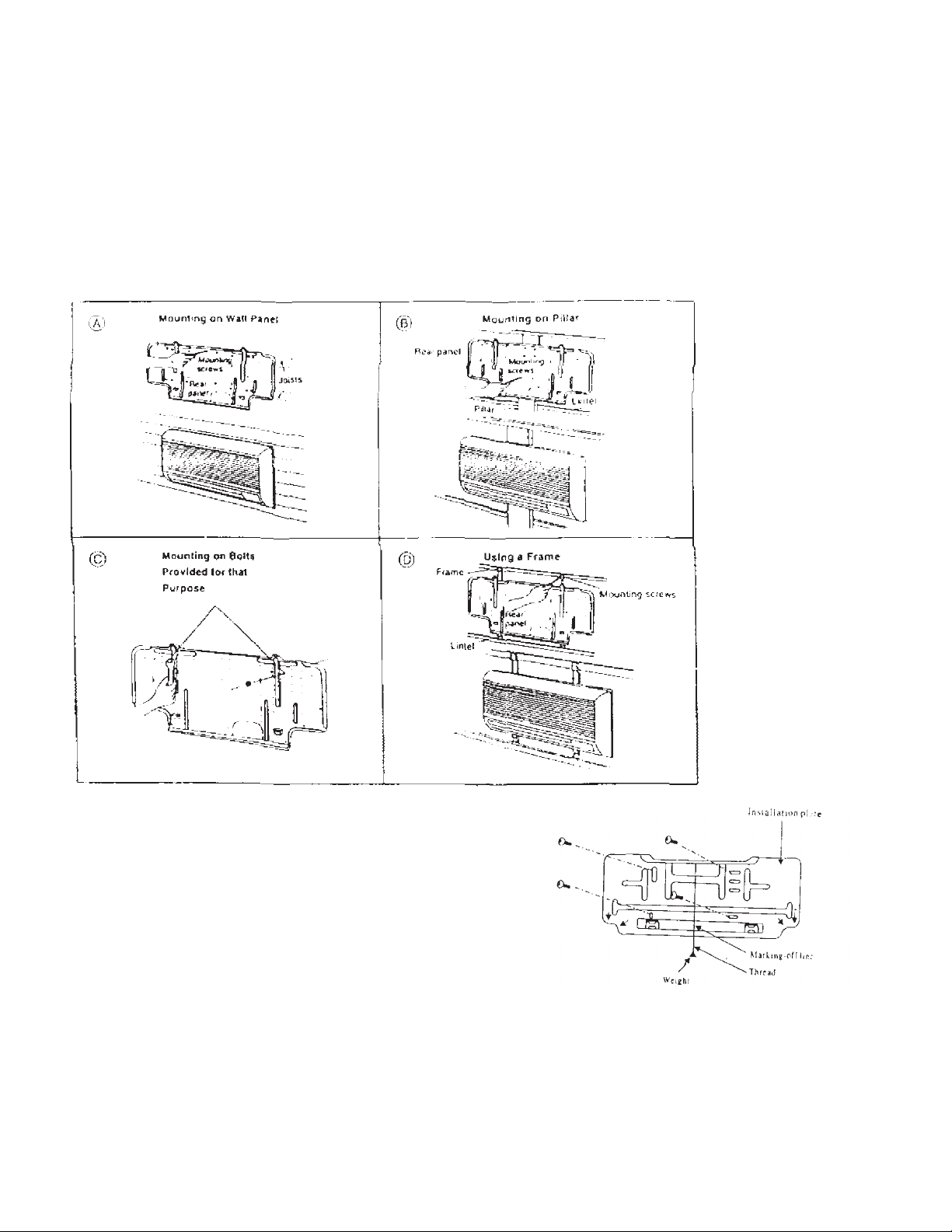
MOUNTING INSTALLATION PLATE:
The fan coil can be installed using any of the four methods described below.
Determine which is the most suitable method.
Position the installation plate on the wall
making sure that it is parallel to the ground.
This can be done by aligning the markingoff line with a thread and weight as shown
in figure on the right. This is to ensure that
the condensate water does not overflow
from the drain pan.
Mount the installation plate with the 4
screws provided. (If the unit is to be
mounted on a concrete wall, consider using
anchor bolts instead of the screws provided.
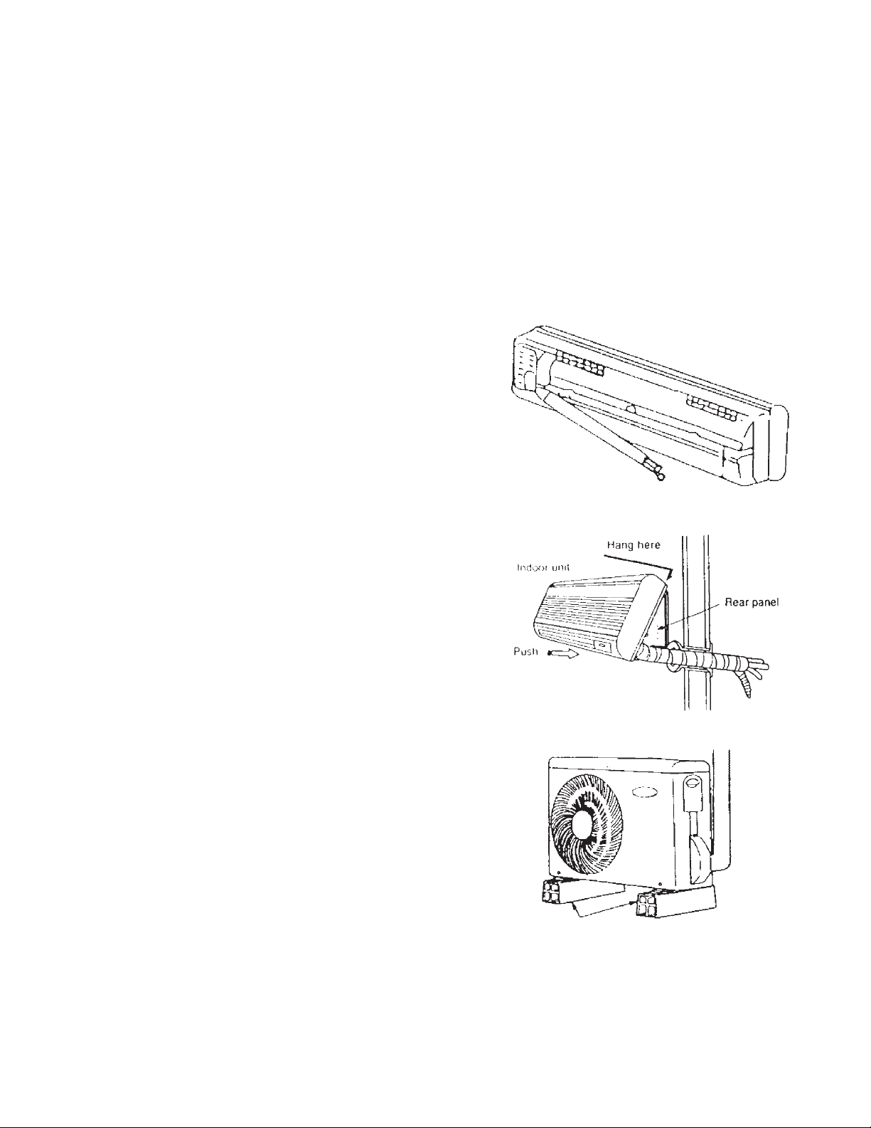
INSTALLATION OF FAN COIL:
The extended liquid and suction pipes and drain hose are hidden inside a slot at the
back of the fan coil. This allows the hole on the wall to be either on the right or left side
of the fan coil.
RIGHT SIDE HOLE POSITION: The piping and drain hose are routed straight through
the hole.
LEFT SIDE HOLE POSITION: The
piping and drain hose run from the
right side to the left side of the unit,
hidden in the slot at the back of the
unit before routing through the hole
on the left side of the unit.
MOUNTING FAN COIL UNIT:
Hook the fan coil onto the upper
portion of the installation plate
ensuring that it sits securely on the
installation plate.
Press the lower portion of the unit
against the installation plate until the
hooks at the back of the unit are
securely engaged with the installation
plate.
MOUNTING CONDENSING UNIT:
Do not place the condensing unit
directly on the ground. It should
preferably be placed on a slightly
raised platform to prevent rain water
from splashing into it. Also ensure
that it is level. Avoid installing the unit
in places where flammable gases
may be present.
beams or blocks
If necessary, due to the placement conditions,
rubber cushions can be placed underneath the
outdoor unit.

REFRIGERATION PIPING & DRAINAGE
PREPARATION OF PIPING
Fan coil and side discharge condensing units are equipped with flare connections. Improper flaring
and brazing may cause refrigerant to leak out of the system. Follow these instructions carefully in
preparing the refrigerant piping.
! Ensure that all piping is of the correct size.
! Measure the distance between the indoor and outdoor units' refrigerant connections, together
with all the curves necessary. Add a few inches as slack.
! Lay the piping as straight as possible on a flat surface and with a pipe cutter, cut the piping
according to the measured length.; Do not tighten the cutter excessively during cutting as this
may cause the pipe to deform. Do not use hacksaw or similar tools to cut the pipe, as it results
in metal shavings getting inside the pipe. This also makes proper flaring impossible.
! Use a reamer to remove burrs from cut edges. Hold the pipe ends upside down to prevent
metal powder from getting into the pipe.
Pipe
Reamer
Note:
As the pipe is round, cutting should be
performed on a straight section. Also,
do not apply too much force with the
blade of the pipe cutter.
Pipe cutter
Keep pipe facing downward
when removing burrs.
! For connection to flare settings, the pipe has to be flared. Remove the flare nut from the unit
and insert it onto the piping.
! Fit the pipe into the bar of the flare tool, about 0.5 mm higher than the surface of the bar.
! Center the flare punch carefully on the pipe and turn gradually to widen the pipe. Check the
finish of the flare to ensure even flaring.
! Cover the flared ends with tape to prevent dust from entering.
Handle
Flaring tool
Flaring bar
Length of periphery portion
Flare nut
L should be constant
0.635 (1/4”) only 0.952 (3/8”) and larger
Approx. 1 mm
0.5 mm
PIPING INSULATION
Liquid and suction lines must be insulated
separately. In a cooling only type air
conditioner, both pipes become cold during
operation. This can cause moisture to
condense on the surface of the pipes,
resulting in heat loss.
PRECAUTIONS WHEN BENDING
PIPES
! The air conditioner's performance
will suffer if the piping is crushed.
! Bend pipes using the pads of your
thumbs to prevent them from
collapsing (See picture on the right.)
! Use a pipe bending tool to bend pipe
wider than 1/2" in diameter.
Insulation
Narrow Pipe
Bend with pads of thumbs
Wide Pipe
Common insulation
Separate insulation is essential
Pipe bending tool
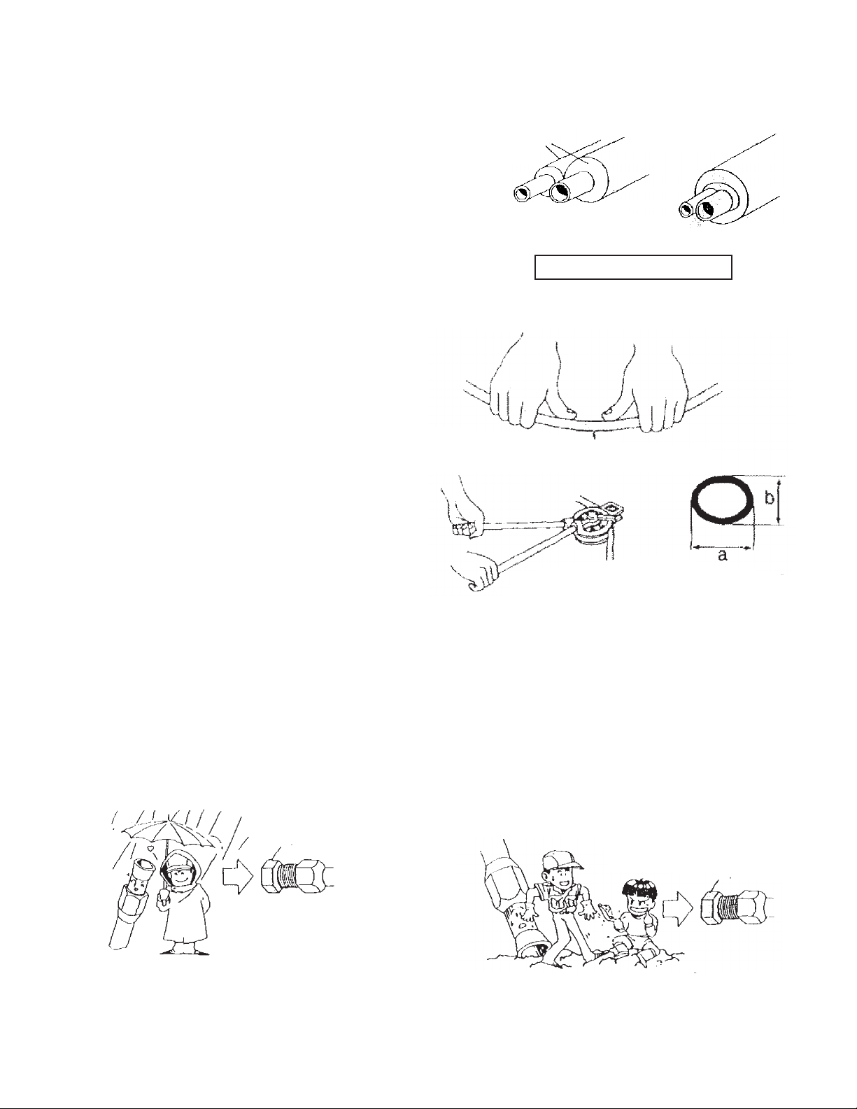
FLARE FITTING CONNECTION. There are 3 piping rules:
(a) DRY: Never allow any water to get
inside the piping.
Cap
Keep cap attached until immediately
before making piping connections.
(b) CLEAN: Never allow dirt, sand or other
foreign particles to get inside the piping.
b/a = 0.7 or more
Cap
Keep cap attached until immediately
before making piping connections.
 Loading...