

Page 1
PHILIPS
AK 640 CD Player
PHILIPS
.'.(GB) - Instructions for lise , Vii-,
. ■'? 4^Ä'rCE)->Mode d'emploi
. Bedienungsanleitung ‘
•' ; • ■ .'<© Gebruiksaanwijzing ,
- ' - ' CD; Instrucciones de manejo - .
' ; - '-’iÍCD' -istruzioni per l'uso , ' ,M;
’ /yC:..'C. Brugsanvisning < ,
^ * ■
- (I!) ^ '
Page 2
INDEX
(0) México «OH
Es necesario que lea cuidadosamente su
instructivo de manejo.
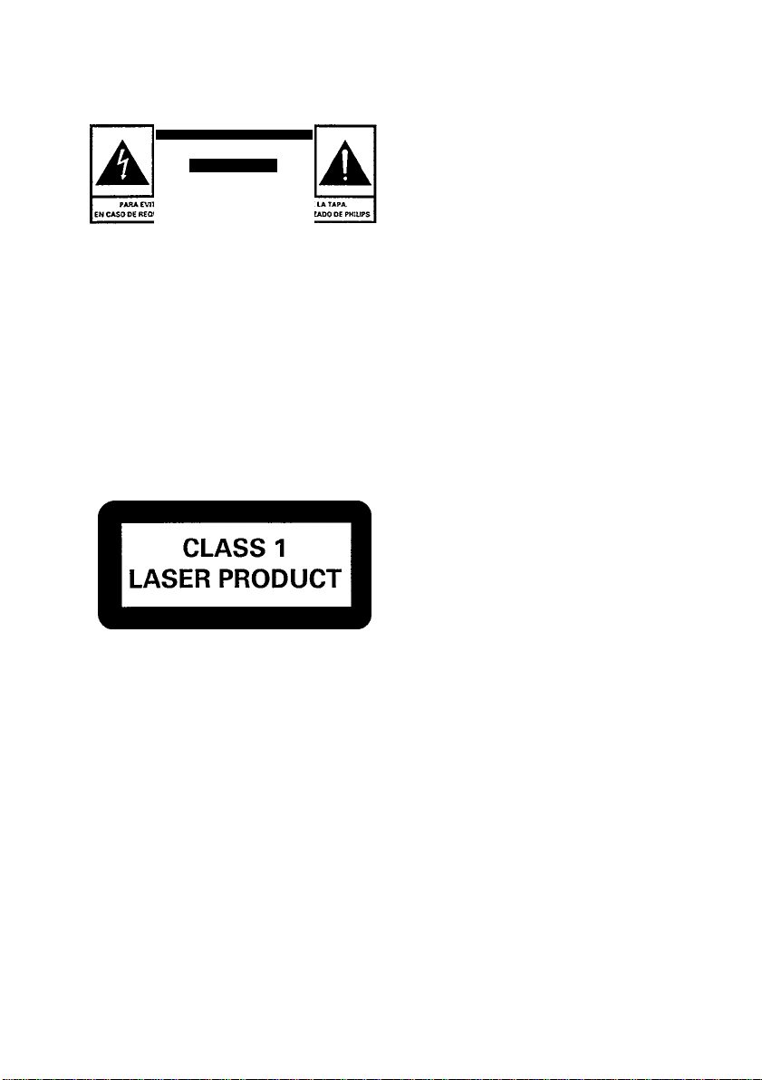
PRECAUCION X ADVERTENCIA
NO ABRIR. RIESGO DE CHOQUE ELECTRICO
ATENCION
NOM
Garantía ... . página 61
Norge
Typeskilt finnes pá apparatens underside.
Observer: Nettbryteren er sekundert innkoplet.
Den innebygde netdelen er derfor ikke frakoplet
nettet sá lenge apparatet er tilsluttet
nettkontakten
Australia
Guarantee ..
.............
page 60
New Zealand
Guarantee
page 60
(Ü) English
Illustrations
CZ) Français
Illustrations
Deutsch
Abbildungen
pages
page 3
page 11 -s
page 3 £
Seite 17
Seite 3
® Nederlands pagina 24
Afbeeldingen pagina 3
©Español
Ilustraciones
página 30
página 3 lïl
O)
c
Ul
O
W
3
o
Q
m
•O
c
«
Ta
G>
■O
O
O
tc
CO
Q.
©Italiano
Illustrazioni
® Dansk
Figurer
© Svenska
Figurer
©Suomi
Kuvat
pagina 36 g
pagina 3 ^
side 42
side 3 á
sida 48 -g
sida 3
sivu 53 -g
sivu 3 ^
a
C
O
C
0)
O
3
Page 3
- - v^. ,*-^-
w' ’ SC/IW u U ■ U U
nn
imJ imJ PROGR lli(^
SHUFFLE FtEPEAT
TRACK
»”Jr B4t/SE no -nn
TIME
Page 4
Page 5

iNSTALLATlON
INSTALLATION
• Unpack all parts and remove protective
material.
• Do not connect the unit to the mains
before checking the mains voltage and
before all other connections have been
made.
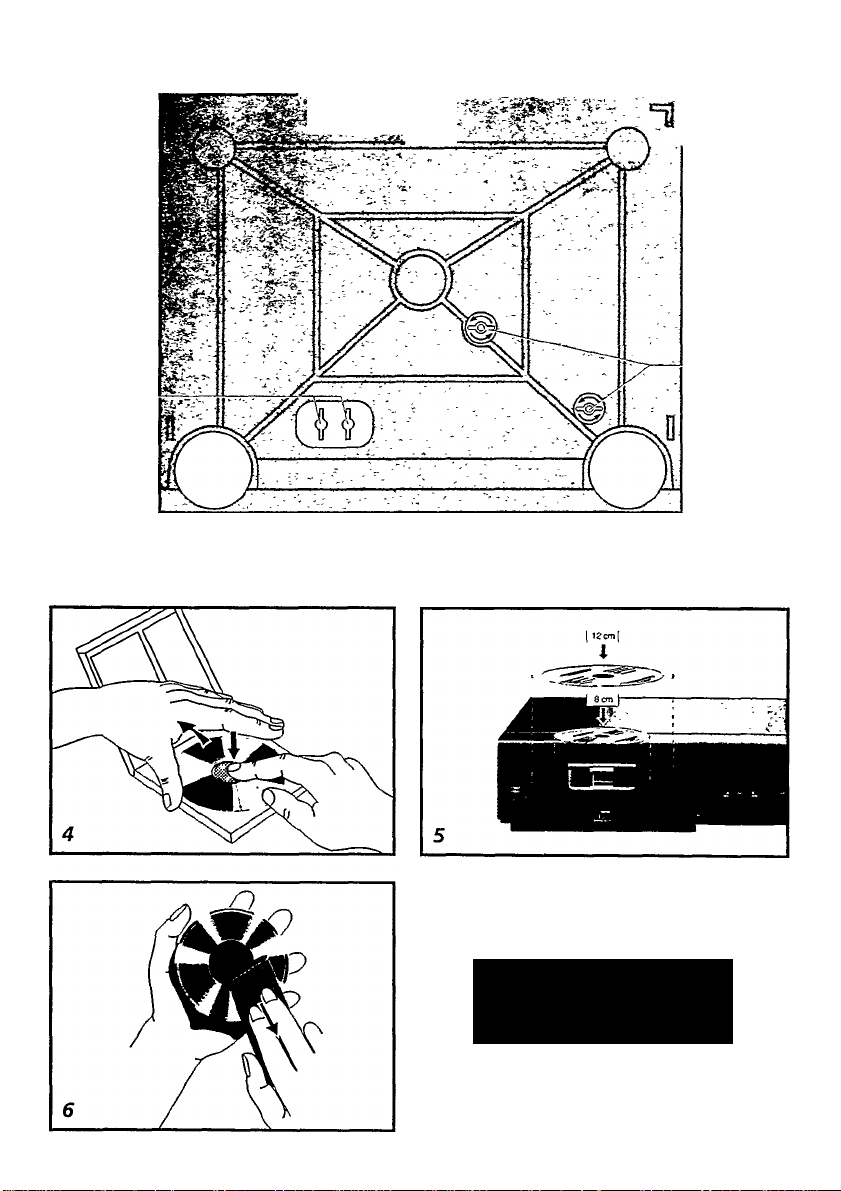
• In the CD tray, there are two red transit
protection clamps, E. These clamps
serve to secure the mechanism of the
CD player to protect it during transport.
Remove the red transit protection
ciamps at the back of the unit and store
them properly in the recesses, F. Should
you wish to transport the unit again, the
mechanism must be secured once more
in order to prevent damages. (See Fig.
3)
• Do not cover any vents and make sure
that there is a space of several centime
tres around the unit for ventilation.
SUPPLY______________________________
• Check that the mains voltage as shown
on the type plate corresponds to your lo
cal mains supply. If it does not, consult
your dealer or service organisation.
• Insert the mains lead connector into the
MAINS input A (See Fig. 2) and the
mains plug into the wall socket. The
mains supply is now connected.
• To disconnect the set from the mains,
withdraw the mains plug from the wall
socket.
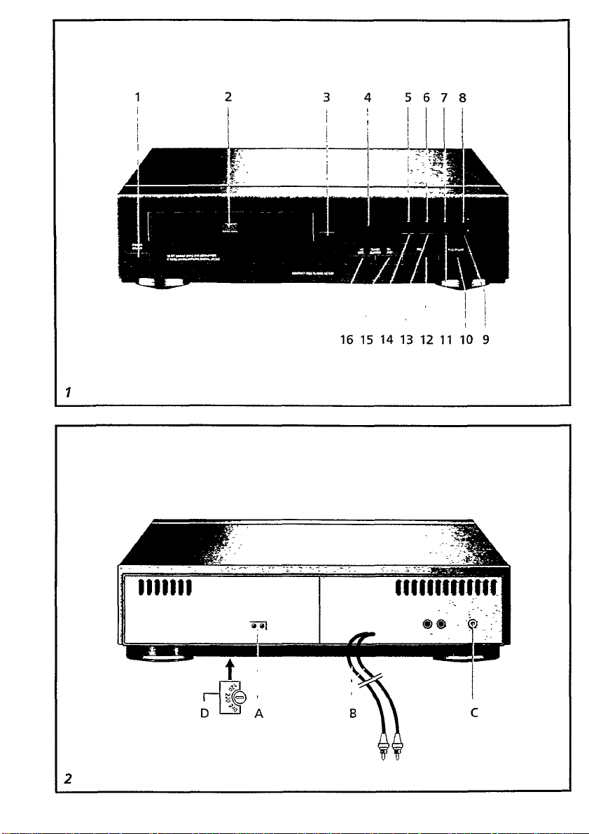
CONNECTIONS (Fig. 2)
• Connect the LINE OUT sockets B of the
CD player to the CD/LINE IN sockets of
your amplifier or receiver.
A) Power cord. Do not connect the unit to
the power without having checked
whether the voltage given on the type
plate corresponds with the local AC outlet
voltage.
B) CD out: two cinch plugs for high quality
Compact Disc playback through your
amplifier, receiver etc.
C) REMOTE IN socket: to connect the unit to
the remote control system of other
equipment.
D) Voltage selector (not all versions). If your
version has this selector, check that the
setting corresponds with your local mains
voltage. The type plate is located on the
rear of the unit.
AC voltage indication is next to voltage
selector on the bottom of the unit.
Important notes for users in the U.K.:
MainsPlug
This apparatus is fitted with an approved
moulded 13 Amp plug.
To change a fuse in this type of plug proceed
as follows:
• Remove fuse cover and fuse.
• Fix new fuse which should be a BS1362
5 A, A.S.T.A. or BSI approved type.
• Refitthefusecover.
If the fitted plug is not suitable for your socket
outlets, it should be cutoff and an appropriate
plug fitted in its place.
If the mains plug contains a fuse, this should
have a value of 5 A. if a plug without a fuse is
used, the fuseatthe distribution board should
not be greater than 5 A.
Note;
The severed plug must be destroyed to avoid a
possible shock hazard should it be inserted
into a 13 A socket elsewhere.
Howto connectaplug
The wires in the mains lead are coloured with
the following code: blue = neutral (N), brown
= live. (L)
As these colours may not correspond with the
colour markings identifying the terminals in
your plug, proceed as follows:
• Connectthebluewiretotheterminalmarked
N or coloured black.
• Connect the brown wire to the terminal
marked L or coloured red.
• Do not connect either wire to the earth
terminal in the plug, marked E (or 4-) or
coloured green (or green and yellow).
Before replacing the plug cover, make certain
that the cord grip is clamped overthe sheath of
the lead - not simply over the two wires.
Copyright
Recording and playback of material may re
quire consent. See Copyright Act 1956 and
The Performer's Protection Acts 1958 to 1972.
•o
TZ
■a
Z
tc
Ul
ja
B
(0
c
cs
a
zc
(0
CO
sz
lU
.5
sz
Q
0)
c
a
o
o
o
(0
Q.
(0
o
c
(0
(0
c
o
>
E
o
3
«
OI
c
s.
c
o
0)
Q>
Page 6

CONTROLS
m
3
w
(S'
ZT
CONTROLS
ON THE UNIT (Fig. 1)
POWER
To switch the CD player on and off.
COMPACT DISC tray
.For 8cm and 12 cm compact discs.
OPEN/CLOSE
To open and close the CD tray
DISPLAY
To indicate what function the unit is
performing:
• TRACK, the total number of tracks in
the disc.
• TIME, the total playing time of the disc
and during playback, the elapsed play
ing time of the current track.
• SCAN, when the INTROSCAN is acti
vated.
• PAUSE, indicating that playback is
interrupted.
• PROGR, indicating a program is played
• REPEAT, indicating that the REPEAT
function is activated.
• SHUFFLE, indicating that the SHUF
FLE function is activated.
• (BO , when using the remote control.
• E. indicating that there is an error.
• P. indicating that the track number has
been programmed in the memory.
• F. indicating that the memory is full.
• C. indicating thatthe memory has been
cleared
REVIEW:
To review the program steps.
PROGRAM
To program the track numbers displayed
into the memory.
CLEAR
To erase a program.
SELECT +
For selecting a different track during
playback or programming.
SELECT-
For selecting a different track during
playback or programming.
10 PLAY/PAUSE Wl
To Start and interrupt playback
11 INTROSCAN
To start programme "Introductory Play" of
a CD.
12 STOP«
To stop playback
13 REPEAT
To repeat a track of a CD, all the tracks in
a disc
14 SHUFFLE
To play all the tracks in a disc in a random
order.
15 NEXT/SEARCH
To select a next track or search for a
passage during playback.
16 PREVIOUS/SEARCH
To return to the start of a track, select a
previous track or search for a passage
during playback.
Page 7

OPERATION
OPERATION
POSITIONING OF THE CD PLAYER
If the CD player is used with Philips system
AS130 or AS230, it is advisable to place your
CD player at the base of the system instead
of the top.
COMPACT DISCS (CD)
Use compact discs bearing the symbol below.
In addition to the conventional 12 cm CDs,
8 cm CDs can be used without an adaptor.
COMPACT
DIGITAL AUDIO
Bear in mind the following points, since any
dirt, scratches or warping of the disc can
cause broken or intermittent sound and also
noise.
• To remove the disc from its case lift it out
by holding the disc’s centre with your
forefinger and the outside of the disc with
your thumb.(Fig. 4)
• When holding the discs, take care not to
touch the playing surface.
• Store the discs in their cases. Return
them to their cases with the label surface
facing up and push down lightly on the
label surface.
• Do not place discs in the following
locations:
- near a heating device ora place where
the temperature is high;
- on a seat or on the dashboard of a
vehicle which is exposed to direct sun
light, since these areas can become
very hot;
- in damp or dusty areas.
• Do not write on the label surface using a
ballpoint pen or hard pencil and do not
stick labels on this surface.
• Wipe away any fingerprints or dust on the
playing surface of a disc using a soft cloth.
Bear in mind the following points:
- always wipe from the inside toward
the outside of the disc; {See Fig. 6)
- do not use conventional record clean
ers, anti-static agents, benzene, thin
ner or other solvents.
FUNCTIONS AND OPERATION
WARNING!
REMOVAL OF PROTECTION CLAMPS
• REMOVE THE RED TRANSIT
PROTECTION CLAMPS AND THE CD
PLAYER IS READY FOR USE.
NOTES:
- DO NOT RE-SECURE THE PROTEC
TION CLAMPS EACH TIME YOU USE
THE CD PLAYER.
PLAY, PROGRAM AND SEARCH FUNCTIONS
Inserting the disc
• Press POWER button to switch the unit
on.
• MU
Press OPEN/CLOSE to open the CD
tray.
- uPCf'J appears on the display.
Insert the CD, printed side up, in the
tray (See Fig. 5).
Press OPEN/CLOSE again to close the
CD tray.
---------cating that the CD player is scanning the
contents list of the CD. After a few sec
onds, the total playing time and the
number of tracks appear on the display.
Playback will start by pressing PLAY/
PAUSE Wl.
As soon as playback starts, the display
shows the track number and the elapsed
playing lime of that title.
appears on the display.
: — appears on the display indi
£
U1
tn
c
Page 8

OPERATION
Playing the entire disc
(Q
- Playback starts with the first track.
- The display shows the current track
number and its elapsed playing time.
- When all the tracks have been played,
the CD player stops and the total
number of tracks and total playing
time are shown on the display.
• To stop playback, press STOP ■ on the
unit.
• To interrupt playback, press PLAY/
PAUSE ►!! on the unit.
• To resume playback, press PLAY/PAUSE
• Press PLAY/PAUSE ►!! on the unit.
5*
►II on the unit again.
• Press POWER button to switch the unit
off.
Note:
Instead of pressing the OPEN/CLOSE button
after inserting the disc, you can also press
the PLAY ► button.
- The CD tray will close and start playback.
Interrupting play
• Press PLAY/PAUSE.
- The display shows
• Press PLAY/PAUSE again if you want to
resume playback.
- PRuSS goes out.
Stopping play
• Press STOP if you wish to stop play. The
total numberof tracks and the total playing
time will now appear in the display.
» Press OPEN/CLOSE to remove the CD.
Playing in a desired order (Program)
By programming the player, you can play up
to 32 tracks in any desired order. If you
exceed the maximum of 32 tracks, the letter
P (FULL) will appear in the display.
• Press PREVIOUS or NEXT briefly (less
than 0.5 second) to locate a particular
track.
• When you have found the correct track
number, press PROGRAM to store it in
the memory.
- The display will show 'P' and the total
playing time on the disc..
• Repeat this procedure to select other
tracks that you wish to programme into
the memory.
- If the unit is in Normal “PLAY”, “SHUF
FLE”, and “INTROSCAN” modes,
you can programme thecurrenttracks.
• During playback, you can program atrack.
- Press SELECT + or SELECT - to
locate a particular track.
- Press PROGRAM when you recog
nise a track which you wish to pro
gramme into the memory
- The display shows P and the total
playing time on the disc.
Playing a program
• Press PLAY/PAUSE.
- "PROGR" appears on the display and
playback starts with the first track of
the program.
- When all tracks have been played, the
display shows the number of tracks
and the playing time of the disc now in
the play position.
Reviewing the program
• To review the tracks which you have
programmed, press REVIEW.
- The programmed tracks will be dis
played. If no programme is available,
will be displayed.
Page 9

OPERATION
Erasing a program
• To clear all programmed tracks, press
CLEAR.
- " will appear on the display.
Note:
- Opening and closing the CD tray and
switching the unit off will also cancel the
programme.
Introductory Play
The INTROSCAN function can be used in
both STOP and PLAY modes by pressing the
INTROSCAN button. The INTROSCAN
function causes the first 10 seconds of every
track on all CDs to be played (If CD is already
in PLAY mode, only the first 10 seconds of
the remaining tracks are played). After playing
the opening seconds of a track, the CD
player jumps to the beginning of the next
track. The corresponding track number
appears in the display.
• Press INTROSCAN on the unit.
- The first ten seconds of each track on
the disc will be played.
- Press PROGRAM when you recog
nise a track which you wish to pro
gramme into the memory
- The display shows and the total
playing time on the disc.
• Press INTROSCAN again if you want to
play the complete track.
- If you press PLAY/PAUSE ►!! during
the introscan mode, then the unit will
resume play mode.
Shuffle Play
All the tracks of the disc can be randomly
played
• Press SHUFFLE on the main unit before
or during play
- The display shows SHUFFLE and play
starts with a track which has been
randomly selected.
- When one track finishes, its number
disappears from the display and an
other track is randomly selected from
those which have not yet been played.
- During play you can press NEXT or
PREVIOUS briefly (less than 0.5 sec
ond) to select another random track.
• Press PROGRAM when you recognise a
track which you wish to programme into
the memory.
• To resume normal play mode, press
SHUFFLE again.
• If you open the CD tray, the shuffle
function will be cancelled.
Repeat Play
If at any time you wish to listen to a disc or
programme over and over again, the REPEAT
function will allow you to do so.
• Press REPEAT on the unit.
The "Repeat" flag will be lighted on.
• Press STOP«. OPEN/CLOSE or
REPEAT to cancel the repeat function.
Selecting a different track during
piayback or programmed play
• Press PREVIOUS or NEXT briefly (less
than 0.5 second) until the required track
number appears in the display.
- Shortly after this, the chosen track will
start playing.
Starting again with the track that is
currently playing
• Press PREVIOUS briefly (less than 0.5
second).
- The track will be started again from the
beginning.
Searching for a passage during playback
or programmed play
• Hold PREVIOUS or NEXT pressed down
to search for the required passage. If you
release the button, play v/ill continue.
Note:
This is an "AUDIBLE SEARCH".
The volume will automatically be reduced to
a low level during search operation and will
return to its normal level when the search
button is released.
JZ
_j2
TO
c
UJ
Page 10

MAINTENANCE
MAINTENANCE
S'
THE SYSTEM
M
3"
• A chamois leather slightly moistened with
water is sufficient for cleaning the housing
of the unit and the enclosures.
• Do not use cleaning agents containing
alcohol, spirits, ammonia or abrasives.
____________________
THE CD PLAYER
• Keep the CD tray free of dust using a
clean cloth.
THE CDs
• Never write on the printed side of a CD.
• Do not attach any stickers to a CD.
• Keep the shiny surface of a CD clean.
Use a soft lint-free cloth and always wipe
the CD in a straight line from centre to
edge. (Fig. 6)
• Never use cleaning agents for
conventional records and grease solvents
or abrasives to clean CDs.
FAULTS AND THEIR LIKELY CAUSES
• If a fault occurs, first check the points
listed below before sending the unit for
repair. If the remedies fail to help, consult
your dealer.
PROBLEMS WITH THE WHOLE SYSTEM
Electrostatic charge may cause unexpected
symptoms. See whether these symptoms
disappear if you unplug the AC cord and plug
it in again after a short period.
CAUTION;
INVISIBLE LASER RADIATION WHEN
OPEN AND INTERLOCKS DEFEATED.
AVOID EXPOSURE TO BEAM.
This product complies with the radio
interference requirements of the European
Community.
Problems with the CD player
- The CD is not inserted properly with the
printed side facing up.
- The CD is dirty, badly scratched or warped.
- Becauseoflargetemperaturedifferences,
condensation has formed on the lens of
the laser. This will disappear after some
time.
10
Page 11

59
Page 12

GUARANTEE AND SERVICE VAUD FOR AUSTRAUA |
The benefits given to the purchaser by this warranty
are in addition to all other rights and remedies, which,
under the Trade Practices Act or other Commonwealth
or State law. the purchaser or owner has in respect of
the product.
The Philips product carries the following warranties
C-series HiFi-systems: 12 months Compact Disc Play
ers; 12 months Home Audio Systems 6 months Clock
radios, portable radios, cassette recorders, cassette
players and radio recorders 90 days
Any defect in materials or workmanship occurring
within the specified period from the date of delivery,
will be rectified free of charge by the retailer from
whom this product was purchased
Note Please retain your purchase docket to assist
prompt service
Conditions of this warranty
1. All claims for warranty service must be made to the
retailer from whom this product was purchased All
transport charges incurred in connection with war
ranty service or replacement will be paid by the
purchaser
2. These warranties do not cover batteries and extend
only to defects in materials or workmanship occur
ring under normal use of the product where operated
in accordance with our instructions
Philips Consumer Products Division.
Technology Park
Figtree Drive, Australia Centre
Homebush 2140, New South Wales
GUARANTEE AND SERIACE FOR NEW ZEALAND
□
Thank-you for purchasing this quality Philips product.
The document you are now reading is your guarantee
card
Guarantee
PhilipsNewZealandLtdguaranteesthisproduct against
defective components and faulty workmanship for a
period of 12 months Any defect in materials or work
manship occurring within 12 months from the date of
purchase subject to the following conditions will be
rectified free of charge by the retailer from whom this
product was purchased
Conditions.
1. The product must have been purchased in New
Zealand, and this guarantee card completed at time
of purchase (this is your proof of the date of pur
chase)
2. The guarantee applies only to faults caused by
defective components, or faulty workmanship on
the part of the manufacturer
3. The guarantee does not cover failures caused by
misuse, neglect, normal wear and tear, accidental
breakage, use on the incorrect voltage, use contrary
to operating instructions, orunauthorised modifica
tion to the product or repair by an unauthorised
technician
4L Reasonable evidence (in the form of a sales docket
or completed guarantee card) must be supplied to
indicate that the product was purchased no more
than 12 months prior to the date of your claim
5. In the event of a failure. Philips shall be under no
liability for any injury, or any loss or damage caused
to propertyor products other than theproduct under
guarantee
This guarantee does not prejudice your rights under
common law and statute, and is in addition to the
normal responsibilities of the retailer and Philips
60
Howto claim.
Should your Philips product fail within the guarantee
period, please return it to the retailer from whom it was
purchased In most cases the retailer will be able to
satisfactorily repair or replace the product
However, should the retailer not be able to conclude
the matter satisfactorily, or if you have other difficul
ties claiming under this guarantee, please contact
The Guarantee Controller,
Philips New Zealand Ltd.
SP.O. Box 41.021
Auckland
Br (09) 84 44 160
Page 13

¡n PAUSE Q t_t. Q n
SHUFFLE REPEAT \V'V^
SCAN i-f ^ • <-f L.I
PBOGR »//Ok
TRACK
TIME
Page 14

Page 15

GABANTfA PARA MEXICO
Este aparato está fabricado con materiales de
alta calidad y ha sido cuidadosamente verificado.
Philips, por lo tanto, da a usted una garantía de 12
meses a partir de su fecha de compra.
La garantía ampara la reposición de las piezas
defectuosas debidas a fallas en su montaje o en
los materiales, incluyendo la mano de obra
necesaria para su reemplazo en nuestras
Sucursales o talleres autorizados.
En caso de fallas en su aparato le rogamos se
sírva poner en contacto con su distribuidor
Esta garantía no cubrirá las averías que resulten
como consecuencia de una instalación incorrecta
del aparato, manifiesto maltrato o uso
inadecuado del mismo
Philips se obliga a reparar y devolver a usted su
aparato en un plazo no mayor de 30 días hábiles
contados a partir de la fecha de haber ingresado
su aparato a uno de nuestros talleres.
Para que esta garantía sea válida, es necesario
que el certificado que figura en la parte posterior
de esté instructivo haya sido debidamente
llenado en el momento de la compra del aparato.
En caso de extravío del certificado con la
presentación de la factura o remisión de su
aparato podrá hacer efectiva la garantía
correspondiente
Si usted tiene alguna duda o pregunta que no le
pueda solucionar su distribuidor, por favor
ponerse en contacto con
This Sign on the packaging
IS onfy meant for Germany
Dieses Zeichen auf der Verpackung
gilt nur fur Deutschland
Le Symbole sur l'emballage
n'a que du sens en Allemagne
Dit symbool op de verpakking
is aileen van toepassmg m Ouitsiand
Esta señal en el paquete
es válida sólo para Aleman'a
Questo simbolo suU imballo
e’ destinato solo alla Germania
Dette maerke pà mdpaknmaen
gælder kun for TysklancT
Detta marke pâ embal'aget ai*
endast avseit for Tyskiand
Tama pakkauksessa eleva merkmta on
tarkoitetto amoastaan saksaa varten
Oficinas Centrales de Servicio,
Av. Coyoacán No. 1051, Col. del Valle,
03100 MÉXICO, D.F.
S 5-75-20-22 o 5-75-01-00
61
Page 16

AK 640
:я41 ()i<-
 Loading...