

Philips ActiLume G2 Product Manual
Product Guide
ActiLume G2 Indus Sensor
H513 N
LRI1668
The Philips ActiLume G2 Indus Sensor H513 N is a small, lightweight multisensor
designed for integration into luminaires.
The ActiLume G2 Indus Sensor H513 N can be used in combination with the ActiLume
DALI gen2 (LLC1663), ActiLume Wireless DALI gen2 (LLC1685) and ActilLume Wireless
1-10V gen2 (LLC1682) controller. The sensor is specically designed to be used in
places with high ceilings such as warehouses; retail shops etc. but can also be applied
in oce or corridor like applications with high ceilings. The multisensor has a passive
infra-red (PIR) receiver for movement detection, an infra-red (IR) receiver for receiving
information (commands, settings and/or selection) from, for example, the IRT9090
infra-red remote, a daylight receiver to provide Daylight Dependent Regulation (DDR)
and a bi-color LED for indication of sensor powered and motion detection.
2
Product Guide - LRI1668
Features and benets
• The Philips ActiLume G2 Indus Sensor H513 N is
a luminaire based detector designed for energy
savings up to 45%.
• The ActiLume G2 Indus Sensor H513 N consists of
three state of the art miniature detectors and when
it is combined with a suitable controller, it forms an
intelligent lighting solution.
• The light sensor is sensitive for visible radiation
(matching the human eye) providing automatic
savings with daylight depending regulation,
without any visible discomfort for the user.
• The ActiLume G2 Indus Sensor H513 N is connected
to the controller by means of a standardized RJ10
(4p4c) connector.
• Factory light level setting is at 250 lux at a
reection factor of 0.2 and the sensor mounted at
a height of 10m.
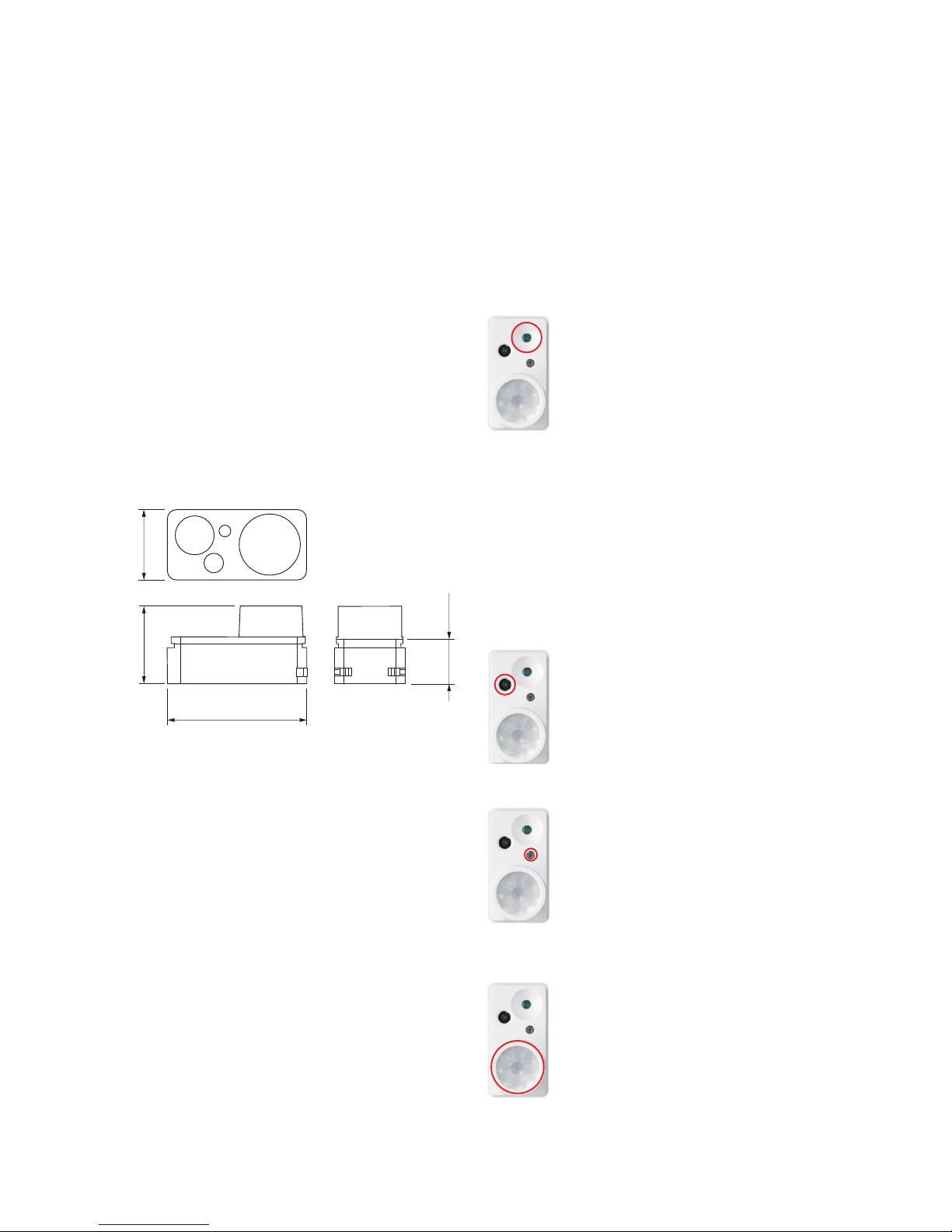
Dimensional drawing
LRI1668 sensor dimensions in mm.
Applications
The ActiLume G2 Indus Sensor H513 N is optimized for
high ceiling situations, warehouses and such, but can
also be used in for other applications.
Commissioning
The ActiLume G2 Indus Sensor H513 N system can,
once it is installed and has been commissioned, work
stand alone.
For commissioning the lighting solution (sensor &
controller) an extensive infrared user interface (remote
control) is available.
• IRT9090 extended IR programming tool
(suited for commissioning and conguration).
Philips quality
This ensures quality with respect to:
• System supplier.
• As manufacturer of lamps, electronic control gear
and lighting control equipment, Philips ensures
that, from the earliest development stage, optimum
performance is maintained.
• International standards.
• Philips lighting control equipment complies with all
relevant international rules and regulations.
Detection patterns of the sensors
Daylight sensor
The light sensor measures the total
amount of light in a circular eld of ≈80%
of the PIR detection area. The following
aspects should be observed during
installation:
• Minimum distance from the window
≥ 0.6m.
• Prevent light reections from outside
entering the sensor (for example
sunlight reection on a car bonnet)
as this will lead to incorrect light
regulation.
As a guideline the formula 0.72 x H
can be used to calculate the minimum
distance between the window and sensor
whereby H is the height from the bottom
of the window to the ceiling.
Infra-Red sensor
The infra-red sensor receives information
(RC5 code) from infra-red transmitters,
such as the IRT9090, and passes the
information on towards the connected
controller. The IR sensor is capable
of receiving signals under an angle of
approximately 15°.
LED indicator
The LED indicator transmits light in two
colors:
• Red when movement is detected.
• Yellow when the LRI1668 sensor is
functioning correctly but no movement
is detected.
When no light is being transmitted the
sensor is not working correctly.
Movement sensor
The detection area for the movement
sensor can be roughly divided into two
parts:
• minor movement (person moving
≤ 0.9 m/s) Ø 5.4 m at 7 m height.
• major movement (person moving
≥ 0.9 m/s) Ø 10.8 m at 13 m height.
25.8 mm
(1.13 in)
48.6 mm (1.91 in)
27.2 mm
(1.07 in)
15.9 mm
(0.63 in)
 Loading...