

Philips A1 A3 service manual

*
Philips A1 and A3 Patient Monitors
A1 Models: M3921A
M3922A
M3923A
M3924A
A3 Models: M3926A
M3927A
M3928A
M3929A
Service Guide
*M3921-9000C
Part Number M3921-9000C
Printed in the U.S.A. February 2002
First Edition

About this Manual
Proprietary Information
This document contains proprietary information, which is protected by copyright. All Rights
Reserved. Reproduction, adaptation, or translation without prior written permission is
prohibited, except as allowed under the copyright laws.
Philips Medical Systems
3000 Minuteman Road
Andover, MA 01810-1085
(978) 687-1501
Publication number
M3921-9000C
Printed in USA
Warranty
The information contained in this document is subject to change without notice.
Philips Medical Systems makes no warranty of any kind with regard to this material,
including, but not limited to, the implied warranties or merchantability and fitness for Philips
Medical Systems shall not be liable for errors contained herein or for incidental or
consequential damages in connection with the furnishing, performance, or use of this material.
Copyright
Printing History
Copyright © 2002 Philips Electronics North America Corporation
New editions of this document incorporate all material updated since the previous edition.
Update packages may be issued between editions and contain replacement and additional
pages to be merged by a revision date at the bottom of the page. Pages that are rearranged due
to changes on a previous page are not considered revised.
The documentation printing date and part number indicate its current edition. The printing
date changes when a new edition is printed. (Minor corrections and updates that are
incorporated at reprint do not cause the date to change.) The document part number changes
when extensive technical changes are incorporated.
This edition, M3921-9000C combines both A1 and A3 Service Guides into one book.
There is no M3921-9000B book.
First Edition............................................................... February 2002
ii

Philips Software License Terms
ATTENTION: USE OF THE SOFTWARE IS SUBJECT TO THE PHILIPS SOFTWARE LICENSE
TERMS SET FORTH BELOW. USING THE SOFTWARE INDICATES YOUR
ACCEPTANCE OF THESE LICENSE TERMS. IF YOU DO NOT ACCEPT THESE
LICENSE TERMS, YOU MAY RETURN THE SOFTWARE FOR A FULL REFUND. IF
THE SOFTWARE IS BUNDLED WITH ANOTHER PRODUCT, YOU MAY RETURN
THE ENTIRE UNUSED PRODUCT FOR A FULL REFUND.
PHILIPS SOFTWARE LICENSE TERMS
The following License Terms govern your use of the accompanying Software unless you have
a separate signed agreement with Philips Medical Systems.
License Grant. Philips Medical Systems grants you a license to Use one copy of the
Software. "Use" means storing, loading, installing, executing or displaying the Software. You
may not modify the Software or disable any licensing or control features of the Software. If
the Software is licensed for "concurrent use", you may not allow more than the maximum
number of authorized users to Use the Software concurrently.
About this Manual
Ownership. The Software is owned and copyrighted by Philips or its third party suppliers.
Your license confers no title to, or ownership in, the Software and is not a sale of any rights in
the Software. Philips’ third party suppliers may protect their rights in the event of any
violation of these License Terms.
Copies and Adaptations. You may only make copies or adaptations of the Software for
archival purposes or when copying or adaptation is an essential step in the authorized Use of
the Software. You must reproduce all copyright notices in the original Software on all copies
or adaptations. You may not copy the Software onto any public network.
No Disassembly or Decryption. You may not disassemble or decompile the Software unless
Philips prior written consent is obtained. In some jurisdictions, Philips consent may not be
required for limited disassembly or decompilation. Upon request, you will provide Philips
with reasonably detailed information regarding any disassembly or decompilation. You may
not decrypt the Software unless decryption is a necessary part of the operation of the
Software.
Transfer. Your license will automatically terminate upon any transfer of the Software. Upon
transfer, you must deliver the Software, including any copies and related documentation, to
the transferee. The transferee must accept these License Terms as a condition to the transfer.
Termination. Philips Medical Systems may terminate your license upon notice for failure to
comply with any of these License Terms. Upon termination, you must immediately destroy
the Software, together with all copies, adaptations and merged portions in any form.
Export Requirements. You may not export or re-export the Software or any copy or
adaptation in violation of any applicable laws or regulations.
U.S. Government Restricted Rights. The Software and any accompanying documentation
have been developed entirely at private expense. They are delivered and licensed as
iii

About this Manual
"commercial computer software" as defined in DFARS 252.227-7013 (Oct. 1988), DFARS
252.211-7015 (May 1991) or DFARS 252.227-7014 (Jun. 1995), as a "commercial item" as
defined in FAR 2.101(a), or as "Restricted computer software" as defined in FAR 52.227-19
(Jun. 1987)(or any equivalent agency regulation or contract clause), whichever is applicable.
You have only those rights provided for such Software and any accompanying documentation
by the applicable FAR or DFARS clause or the Philips standard software agreement for the
product involved.
iv

Text Conventions
The following conventions for Notes, Cautions, and Warnings are used in this manual.
NOTE
A Note calls attention to an important point in the text.
A Caution calls attention to a condition or possible situation that could damage or destroy the
product or the user’s work.
A Warning calls attention to a condition or possible situation that could cause injury to
the user and/or patient.
About this Manual
Caution
WarningWarning
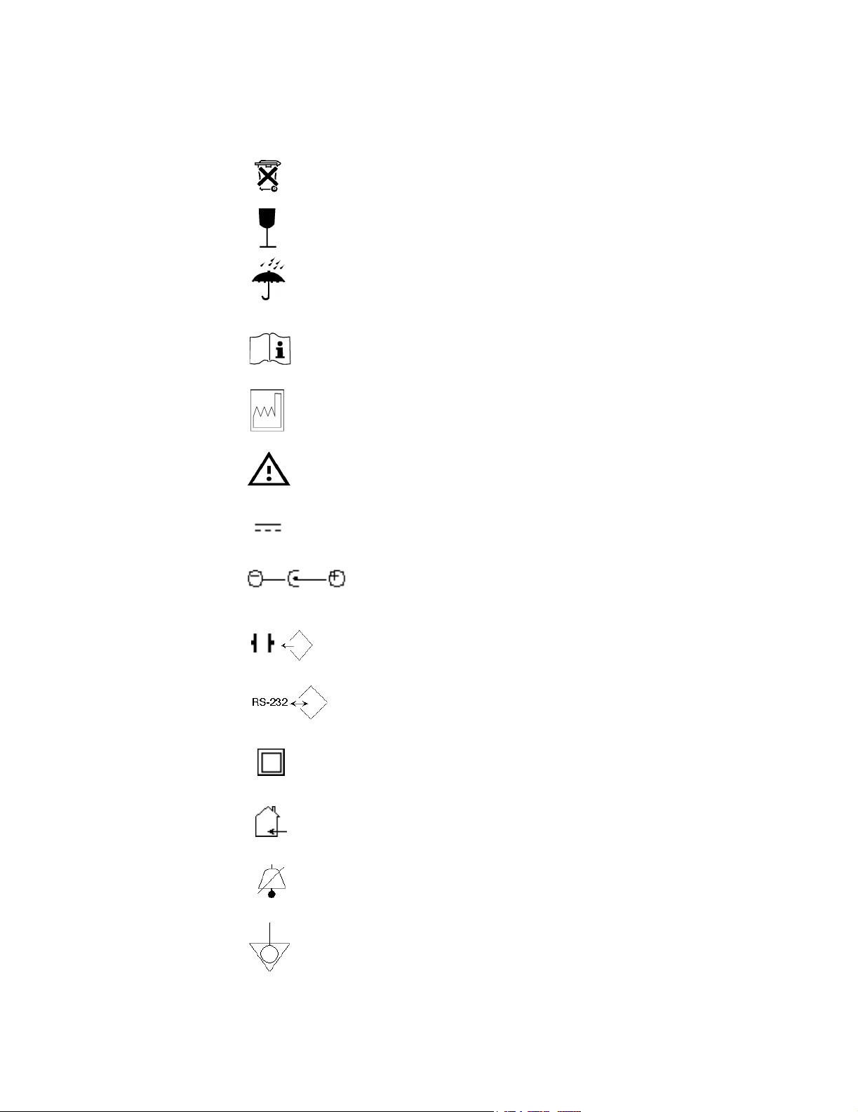
Explanation of Symbols
Symbols on products and packaging mean the following:
Battery Gauge icon
Defibrillator-proof type CF equipment
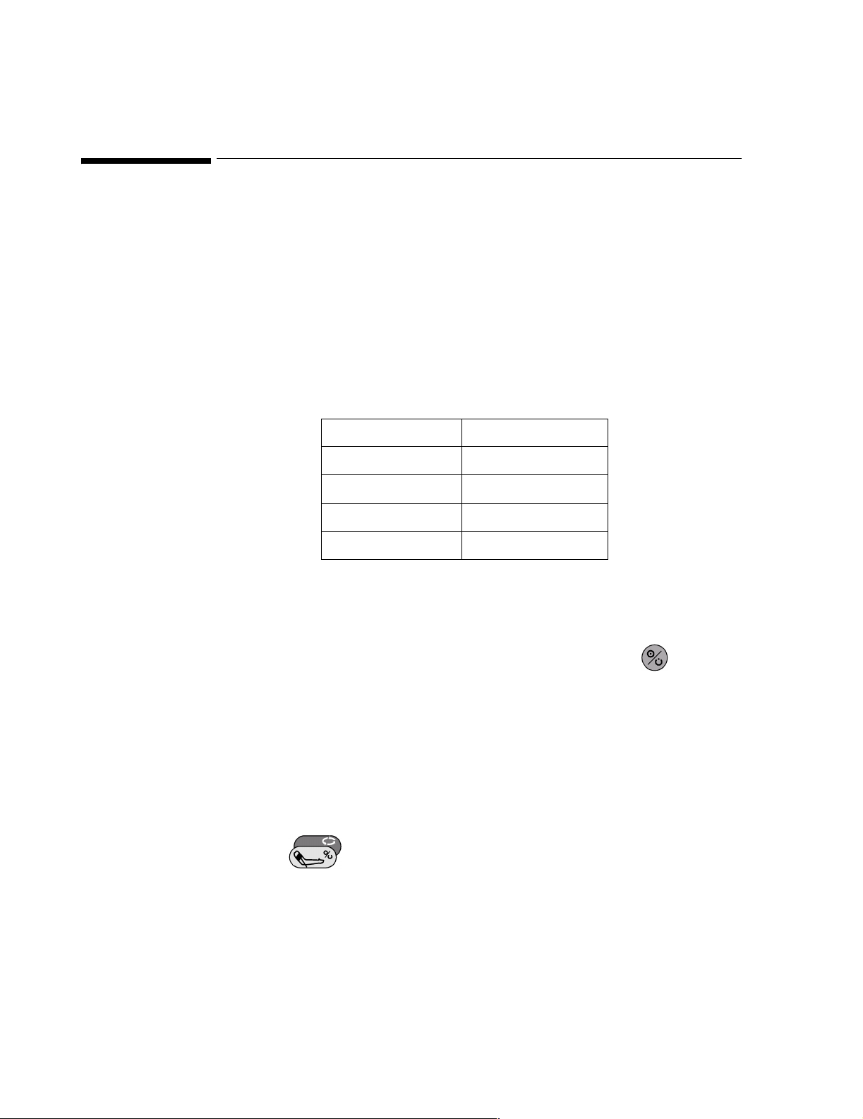
On/Standby button.
Alarm Limits icon.
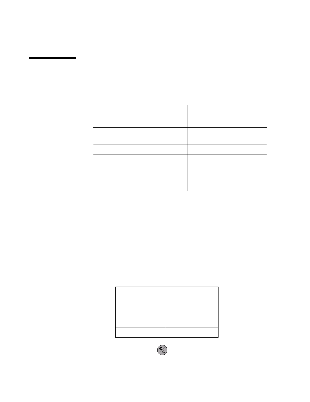
Adjust Screen Contrast to display (monochrome) or invert the video to (color).
Adjust Heart Rate Tone volume.
Initiate NiBP measurement
v

About this Manual
T
Temperature
NiBP
ECG
SpO
2
SpO
2
Located on recorder. Produces a 20 Second Snapshot
Located on recorder. Produces a Continuous Print
Signal (ECG) Input
Signal (ECG) Output
Data input/output
Alternating Current
Direct Current
Temperature
Humidity
Altitude or atmospheric pressure
vi
About this Manual
Contains parts that may not be put into normal waste disposal but must be recycled or
dealt wi disposed as chemical waste
Fragile, handle with care
Keep dry
Consult instructions for use
Date of manufacture
Refer to User’s Guide
DC Lines
DC Input
Defib Sync.
RS-232 I/O
Class II Equipment
Power supply if for indoor use only
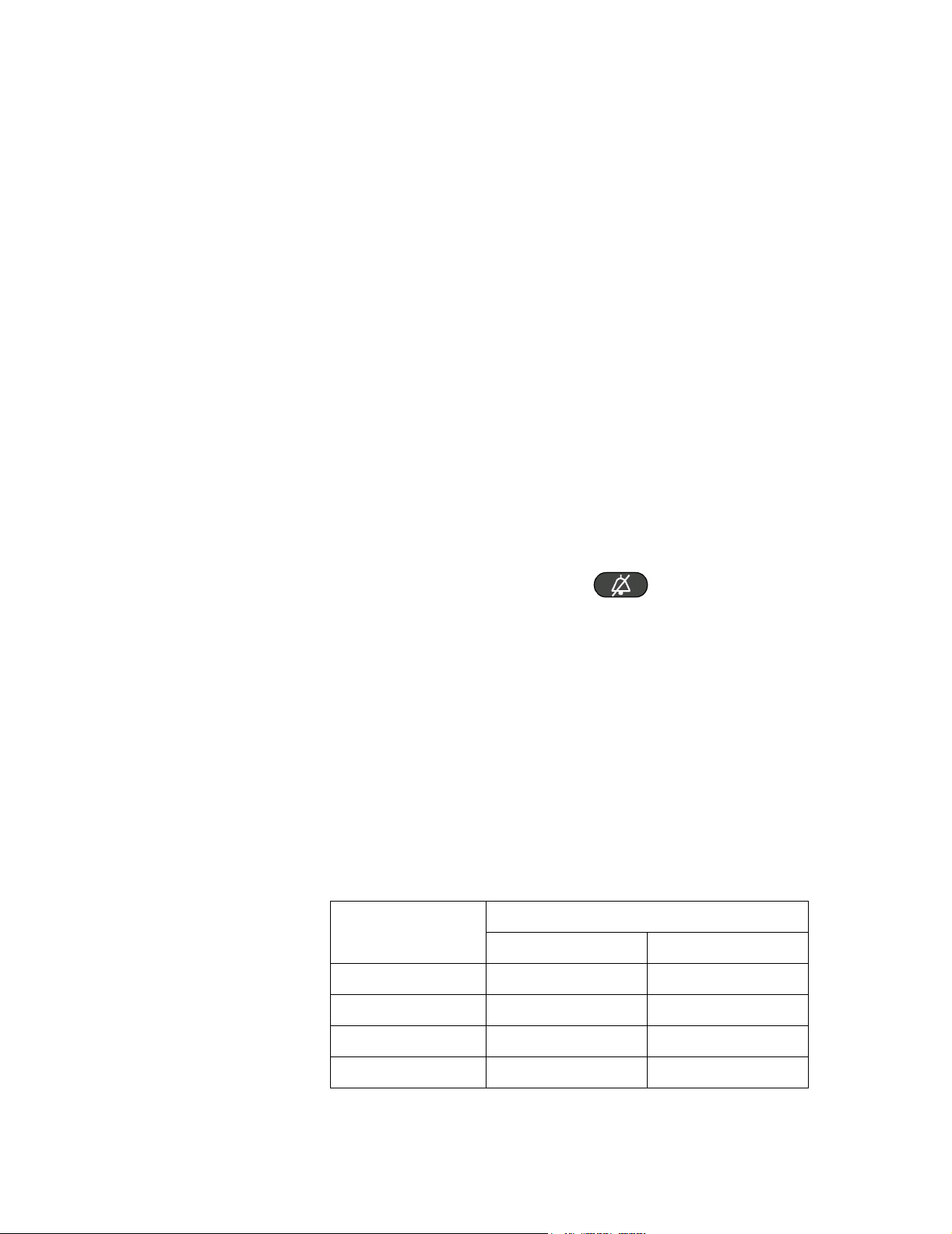
Silence Alarm
Equipotential Ground
vii

About this Manual
Recorder’s front-panel charging LED
Recorder’s front-panel communication LED
Ground Wire
viii

Contents
1. Introduction . . . . . . . . . . . . . . . . . . . . . . . . . . . . . . . . . . . . . . . . . . . . . . . . . . . . . . . . 1
Manual Overview . . . . . . . . . . . . . . . . . . . . . . . . . . . . . . . . . . . . . . . . . . . . . . . . . . . . . . . . . . 1
Patient Monitor Description . . . . . . . . . . . . . . . . . . . . . . . . . . . . . . . . . . . . . . . . . . . . . . . . . . 2
Introduction to External Recorder (M3925A) . . . . . . . . . . . . . . . . . . . . . . . . . . . . . . . . . . . . . 3
Related Documents . . . . . . . . . . . . . . . . . . . . . . . . . . . . . . . . . . . . . . . . . . . . . . . . . . . . . . . . 3
2. Routine Maintenance . . . . . . . . . . . . . . . . . . . . . . . . . . . . . . . . . . . . . . . . . . . . . . . . . 5
Cleaning . . . . . . . . . . . . . . . . . . . . . . . . . . . . . . . . . . . . . . . . . . . . . . . . . . . . . . . . . . . . . . . . 5
Periodic Safety And Functional Checks . . . . . . . . . . . . . . . . . . . . . . . . . . . . . . . . . . . . . . . . 5
Battery . . . . . . . . . . . . . . . . . . . . . . . . . . . . . . . . . . . . . . . . . . . . . . . . . . . . . . . . . . . . . . . . . . 5
Environmental Protection . . . . . . . . . . . . . . . . . . . . . . . . . . . . . . . . . . . . . . . . . . . . . . . . . . . . 6
3. Performance Verification. . . . . . . . . . . . . . . . . . . . . . . . . . . . . . . . . . . . . . . . . . . . . . 7
Introduction . . . . . . . . . . . . . . . . . . . . . . . . . . . . . . . . . . . . . . . . . . . . . . . . . . . . . . . . . . . . . . 7
Test And Inspection Matrix. . . . . . . . . . . . . . . . . . . . . . . . . . . . . . . . . . . . . . . . . . . . . . . . . . . 8
Equipment Needed . . . . . . . . . . . . . . . . . . . . . . . . . . . . . . . . . . . . . . . . . . . . . . . . . . . . . . . 10
Performance Tests. . . . . . . . . . . . . . . . . . . . . . . . . . . . . . . . . . . . . . . . . . . . . . . . . . . . . . . . 11
Battery Charge . . . . . . . . . . . . . . . . . . . . . . . . . . . . . . . . . . . . . . . . . . . . . . . . . . . . . . . . . . . 11
Battery Performance Test . . . . . . . . . . . . . . . . . . . . . . . . . . . . . . . . . . . . . . . . . . . . . . . . . . 12
Power-On Self-Test . . . . . . . . . . . . . . . . . . . . . . . . . . . . . . . . . . . . . . . . . . . . . . . . . . . . . . . 13
Hardware and Software Tests . . . . . . . . . . . . . . . . . . . . . . . . . . . . . . . . . . . . . . . . . . . . . . . 14
Testing . . . . . . . . . . . . . . . . . . . . . . . . . . . . . . . . . . . . . . . . . . . . . . . . . . . . . . . . . 14
SpO
2
Operation with an ECG Simulator . . . . . . . . . . . . . . . . . . . . . . . . . . . . . . . . . . . . . . . . . 17
Operation with a Respiration Simulator (A3 only) . . . . . . . . . . . . . . . . . . . . . . . . . . . . . 18
Verification of Pneumatic System . . . . . . . . . . . . . . . . . . . . . . . . . . . . . . . . . . . . . . . . . 19
Operation with a Temperature Simulator (A1 only) . . . . . . . . . . . . . . . . . . . . . . . . . . . . 25
Operation with a Temperature Simulator (A3 only) . . . . . . . . . . . . . . . . . . . . . . . . . . . . 25
General Operation . . . . . . . . . . . . . . . . . . . . . . . . . . . . . . . . . . . . . . . . . . . . . . . . . . . . . . . . 26
Serial Interface Test . . . . . . . . . . . . . . . . . . . . . . . . . . . . . . . . . . . . . . . . . . . . . . . . . . . . 26
Printer Verification (For A1 Optional Printer M3925A) . . . . . . . . . . . . . . . . . . . . . . . . . . 28
Safety Tests . . . . . . . . . . . . . . . . . . . . . . . . . . . . . . . . . . . . . . . . . . . . . . . . . . . . . . . . . . . . . 29
Ground Integrity . . . . . . . . . . . . . . . . . . . . . . . . . . . . . . . . . . . . . . . . . . . . . . . . . . . . . . . 29
Electrical Leakage . . . . . . . . . . . . . . . . . . . . . . . . . . . . . . . . . . . . . . . . . . . . . . . . . . . . . 31
4. Power-up Defaults Menu And Diagnostic Mode . . . . . . . . . . . . . . . . . . . . . . . . . . 37
Introduction . . . . . . . . . . . . . . . . . . . . . . . . . . . . . . . . . . . . . . . . . . . . . . . . . . . . . . . . . . . . . 37
Power-up Defaults Menu . . . . . . . . . . . . . . . . . . . . . . . . . . . . . . . . . . . . . . . . . . . . . . . . . . . 37
Diagnostic Mode . . . . . . . . . . . . . . . . . . . . . . . . . . . . . . . . . . . . . . . . . . . . . . . . . . . . . . . . . 40
Error Codes . . . . . . . . . . . . . . . . . . . . . . . . . . . . . . . . . . . . . . . . . . . . . . . . . . . . . . . . . . 40
System Information . . . . . . . . . . . . . . . . . . . . . . . . . . . . . . . . . . . . . . . . . . . . . . . . . . . . 41
System A/D Values . . . . . . . . . . . . . . . . . . . . . . . . . . . . . . . . . . . . . . . . . . . . . . . . . . . . 42
NIBP Test . . . . . . . . . . . . . . . . . . . . . . . . . . . . . . . . . . . . . . . . . . . . . . . . . . . . . . . . . . . . 43
Restoring Factory Settings. . . . . . . . . . . . . . . . . . . . . . . . . . . . . . . . . . . . . . . . . . . . . . . . . . 45
Contents ix

5. Troubleshooting. . . . . . . . . . . . . . . . . . . . . . . . . . . . . . . . . . . . . . . . . . . . . . . . . . . . 49
Introduction. . . . . . . . . . . . . . . . . . . . . . . . . . . . . . . . . . . . . . . . . . . . . . . . . . . . . . . . . . . . . . 49
How To Use This Section . . . . . . . . . . . . . . . . . . . . . . . . . . . . . . . . . . . . . . . . . . . . . . . . . . . 49
Who Should Perform Repairs. . . . . . . . . . . . . . . . . . . . . . . . . . . . . . . . . . . . . . . . . . . . . . . . 49
Replacement Level Supported . . . . . . . . . . . . . . . . . . . . . . . . . . . . . . . . . . . . . . . . . . . . . . . 49
Obtaining Replacement Parts. . . . . . . . . . . . . . . . . . . . . . . . . . . . . . . . . . . . . . . . . . . . . . . . 50
Troubleshooting Guide . . . . . . . . . . . . . . . . . . . . . . . . . . . . . . . . . . . . . . . . . . . . . . . . . . . . . 50
Power . . . . . . . . . . . . . . . . . . . . . . . . . . . . . . . . . . . . . . . . . . . . . . . . . . . . . . . . . . . . . . . 50
Error Codes . . . . . . . . . . . . . . . . . . . . . . . . . . . . . . . . . . . . . . . . . . . . . . . . . . . . . . . . . . 53
Generating an Error Log Printout (A1 only) . . . . . . . . . . . . . . . . . . . . . . . . . . . . . . . . . . 53
Serviceable Hardware Error Codes . . . . . . . . . . . . . . . . . . . . . . . . . . . . . . . . . . . . . . . . 54
Other Error Codes (All Monitors) . . . . . . . . . . . . . . . . . . . . . . . . . . . . . . . . . . . . . . . . . . 57
Buttons/Wheels (All Monitors) . . . . . . . . . . . . . . . . . . . . . . . . . . . . . . . . . . . . . . . . . . . . 58
Display/Audible Tones (All Monitors) . . . . . . . . . . . . . . . . . . . . . . . . . . . . . . . . . . . . . . . 59
Operational Performance . . . . . . . . . . . . . . . . . . . . . . . . . . . . . . . . . . . . . . . . . . . . . . . . 60
6. Disassembly Guide . . . . . . . . . . . . . . . . . . . . . . . . . . . . . . . . . . . . . . . . . . . . . . . . . 63
Introduction. . . . . . . . . . . . . . . . . . . . . . . . . . . . . . . . . . . . . . . . . . . . . . . . . . . . . . . . . . . . . . 63
How To Use This Chapter . . . . . . . . . . . . . . . . . . . . . . . . . . . . . . . . . . . . . . . . . . . . . . . . . . 64
Disassembly Procedures (A1) . . . . . . . . . . . . . . . . . . . . . . . . . . . . . . . . . . . . . . . . . . . . . . . 65
Closed Case Disassembly Procedures . . . . . . . . . . . . . . . . . . . . . . . . . . . . . . . . . . . . . 65
Separation of Front and Rear Case Assemblies . . . . . . . . . . . . . . . . . . . . . . . . . . . . . . 68
Front Case Disassembly Procedures . . . . . . . . . . . . . . . . . . . . . . . . . . . . . . . . . . . . . . . 70
Rear Case Disassembly Procedures . . . . . . . . . . . . . . . . . . . . . . . . . . . . . . . . . . . . . . . 75
Main PCB Disassembly Procedures. . . . . . . . . . . . . . . . . . . . . . . . . . . . . . . . . . . . . . . . 77
Disassembly Procedures (A3) . . . . . . . . . . . . . . . . . . . . . . . . . . . . . . . . . . . . . . . . . . . . . . . 79
Closed Case Disassembly Procedures . . . . . . . . . . . . . . . . . . . . . . . . . . . . . . . . . . . . . 79
Separation of Front and Rear Case Assemblies . . . . . . . . . . . . . . . . . . . . . . . . . . . . . . 80
Front Case Disassembly Procedures . . . . . . . . . . . . . . . . . . . . . . . . . . . . . . . . . . . . . . . 82
Rear Case Disassembly Procedures . . . . . . . . . . . . . . . . . . . . . . . . . . . . . . . . . . . . . . . 85
7. Spare Parts . . . . . . . . . . . . . . . . . . . . . . . . . . . . . . . . . . . . . . . . . . . . . . . . . . . . . . . . 91
Introduction. . . . . . . . . . . . . . . . . . . . . . . . . . . . . . . . . . . . . . . . . . . . . . . . . . . . . . . . . . . . . . 91
Small Parts Kit . . . . . . . . . . . . . . . . . . . . . . . . . . . . . . . . . . . . . . . . . . . . . . . . . . . . . . . . . . . 91
Top Level Assembly . . . . . . . . . . . . . . . . . . . . . . . . . . . . . . . . . . . . . . . . . . . . . . . . . . . . . . . 92
Front Case Assembly . . . . . . . . . . . . . . . . . . . . . . . . . . . . . . . . . . . . . . . . . . . . . . . . . . . . . . 97
Rear Case Assembly . . . . . . . . . . . . . . . . . . . . . . . . . . . . . . . . . . . . . . . . . . . . . . . . . . . . . 103
Main PCB Assembly (A1) . . . . . . . . . . . . . . . . . . . . . . . . . . . . . . . . . . . . . . . . . . . . . . . . . . 107
Power Supply, Cables, and Miscellaneous Parts . . . . . . . . . . . . . . . . . . . . . . . . . . . . . . . . 109
Exchange Unit Part Numbers . . . . . . . . . . . . . . . . . . . . . . . . . . . . . . . . . . . . . . . . . . . . . . . 112
8. Packing For Shipment . . . . . . . . . . . . . . . . . . . . . . . . . . . . . . . . . . . . . . . . . . . . . . 113
General Instructions . . . . . . . . . . . . . . . . . . . . . . . . . . . . . . . . . . . . . . . . . . . . . . . . . . . . . . 113
Repacking In Original Carton . . . . . . . . . . . . . . . . . . . . . . . . . . . . . . . . . . . . . . . . . . . . . . . 113
Repacking In A Different Carton. . . . . . . . . . . . . . . . . . . . . . . . . . . . . . . . . . . . . . . . . . . . . 113
x Contents

9. RS-232 Interface . . . . . . . . . . . . . . . . . . . . . . . . . . . . . . . . . . . . . . . . . . . . . . . . . . 115
Cable Connections . . . . . . . . . . . . . . . . . . . . . . . . . . . . . . . . . . . . . . . . . . . . . . . . . . . . . . .116
Nurse Call . . . . . . . . . . . . . . . . . . . . . . . . . . . . . . . . . . . . . . . . . . . . . . . . . . . . . . . . . . . . . . 116
10. Training Program. . . . . . . . . . . . . . . . . . . . . . . . . . . . . . . . . . . . . . . . . . . . . . . . . 117
Introduction . . . . . . . . . . . . . . . . . . . . . . . . . . . . . . . . . . . . . . . . . . . . . . . . . . . . . . . . . . . . .117
Levels of Involvement . . . . . . . . . . . . . . . . . . . . . . . . . . . . . . . . . . . . . . . . . . . . . . . . . . . . . 117
Preventative Maintenance Only . . . . . . . . . . . . . . . . . . . . . . . . . . . . . . . . . . . . . . . . . . 117
Phone Support or Service . . . . . . . . . . . . . . . . . . . . . . . . . . . . . . . . . . . . . . . . . . . . . . .117
Training Materials . . . . . . . . . . . . . . . . . . . . . . . . . . . . . . . . . . . . . . . . . . . . . . . . . . . . . . . . 118
Essential Materials . . . . . . . . . . . . . . . . . . . . . . . . . . . . . . . . . . . . . . . . . . . . . . . . . . . . 118
Optional Materials . . . . . . . . . . . . . . . . . . . . . . . . . . . . . . . . . . . . . . . . . . . . . . . . . . . . . 118
Overview . . . . . . . . . . . . . . . . . . . . . . . . . . . . . . . . . . . . . . . . . . . . . . . . . . . . . . . . . . . . . . . 119
Support Strategies. . . . . . . . . . . . . . . . . . . . . . . . . . . . . . . . . . . . . . . . . . . . . . . . . . . . . . . .120
Unit exchange . . . . . . . . . . . . . . . . . . . . . . . . . . . . . . . . . . . . . . . . . . . . . . . . . . . . . . . . 120
Bench repair . . . . . . . . . . . . . . . . . . . . . . . . . . . . . . . . . . . . . . . . . . . . . . . . . . . . . . . . .120
Theory of Operation and System Architecture . . . . . . . . . . . . . . . . . . . . . . . . . . . . . . . . . . 121
General . . . . . . . . . . . . . . . . . . . . . . . . . . . . . . . . . . . . . . . . . . . . . . . . . . . . . . . . . . . . .121
System Overview - A1 . . . . . . . . . . . . . . . . . . . . . . . . . . . . . . . . . . . . . . . . . . . . . . . . . . 121
Block Diagram - A1 . . . . . . . . . . . . . . . . . . . . . . . . . . . . . . . . . . . . . . . . . . . . . . . . . . . . 121
Block Diagram - A1 . . . . . . . . . . . . . . . . . . . . . . . . . . . . . . . . . . . . . . . . . . . . . . . . . . . . 122
System Overview - A3 . . . . . . . . . . . . . . . . . . . . . . . . . . . . . . . . . . . . . . . . . . . . . . . . . . 123
Block Diagram - A3 . . . . . . . . . . . . . . . . . . . . . . . . . . . . . . . . . . . . . . . . . . . . . . . . . . . . 123
Block Diagram - A3 . . . . . . . . . . . . . . . . . . . . . . . . . . . . . . . . . . . . . . . . . . . . . . . . . . . . 124
Troubleshooting. . . . . . . . . . . . . . . . . . . . . . . . . . . . . . . . . . . . . . . . . . . . . . . . . . . . . . . . . .129
Disassembly . . . . . . . . . . . . . . . . . . . . . . . . . . . . . . . . . . . . . . . . . . . . . . . . . . . . . . . . . . . . 130
Monitor Applications and Algorithms . . . . . . . . . . . . . . . . . . . . . . . . . . . . . . . . . . . . . . . . . . 132
Reference Documents and Other Sources . . . . . . . . . . . . . . . . . . . . . . . . . . . . . . . . . . 132
Preventative Maintenance . . . . . . . . . . . . . . . . . . . . . . . . . . . . . . . . . . . . . . . . . . . . . . . . . 133
Index
Contents xi

xii Contents

Manual Overview
1
Introduction
This manual contains information for servicing the A1 and A3 patient
monitors, subsequently referred to as the monitor throughout this manual.
Only where there are differences in service procedures for the two monitor
types is each monitor referred to specifically as A1 and A3. Only qualified
service personnel should service this product. Before servicing the monitor,
read the User Guide carefully for a thorough understanding of operation.
Introduction 1

Patient Monitor Description
Patient Monitor Description
The purpose and function of the patient monitor is to monitor: ECG; heart
rate; noninvasive blood pressure (systolic, diastolic, and mean arterial
pressures); functional arterial oxygen saturation; respiration rate (A3 only);
and temperature for adult and pediatric patients in all hospital areas and
hospital-type facilities. It can be used during hospital transport and in mobile,
land-based environments, such as ambulances.
The physical and operational characteristics of the monitor are described in
the User Guide.
The measurement parameters and features for each model are indicated
below.
Model
NIBP SpO
M3921A Yes Yes No No No No Mono
M3922A Yes Yes Yes No No No Mono
M3923A Yes Yes No Yes No No Mono
M3924A Yes Yes Yes Yes No No Mono
M3925A Optional Standalone Recorder for A1
M3926A Yes Yes Yes Yes Yes
M3927A Yes Yes Yes Yes Yes
M3928A Yes Yes Yes Yes Yes
M3929A Yes Yes Yes Yes Yes
Measurement Parameters and Features
Temp ECG Resp Integral
2
A1 Monitor
A3 Monitor
Recorder
No
Yes
No
Yes
Color/
Mono
Mono
Mono
Color
Color
2 Introduction

Introduction to External Recorder (M3925A)
The recorder is an optional, standalone printer designed for use with the A1
patient monitor. The recorder communicates with the monitor using a nullmodem cable connected between each device’s RS-232 connector.
The recorder contains an internal battery, which, when fully charged, will
operate the recorder for 3 hours (typical, at 25°C, producing fifteen 20-second
printouts per hour). The recorder can be connected to AC power using an
external power supply. The recorder uses the same type of power supply as
the A1 monitor, the PS-120V or PS-240V.
The recorder does not have an On/Off switch. The recorder can sense when it
has an established communication link with the monitor. At that time, the
green LINKED indicator on the front panel lights, indicating that the recorder
is ready for operation. See the recorder’s User Guide for more information
regarding its operation.
Introduction to External Recorder (M3925A)
Related Documents
To perform test and troubleshooting procedures and to understand the
principles of operation and circuit analysis sections of this manual, you must
know how to operate the monitor. Refer to the User Guide to understand the
various sensors, ECG lead, blood pressure cuffs, and temperature probes that
work with the monitor. Refer also to the user guide and individual directions
for use that accompany these accessories.
Introduction 3

Related Documents
4 Introduction

Routine Maintenance
Cleaning
Warning Do not immerse the monitor or its accessories in liquid or
clean with caustic or abrasive cleaners. Do not spray or
pour any liquid on the monitor or its accessories.
To clean the monitor, dampen a cloth with a commercial, nonabrasive cleaner
and wipe the exterior surfaces lightly. Do not allow any liquids to come in
contact with the power connector or switches. Do not allow any liquids to
penetrate connectors or openings in the instrument. For cables, sensors and
cuffs, follow the cleaning instructions in the directions for use that accompany
these accessories.
2
Periodic Safety And Functional Checks
The monitor requires cleaning, battery maintenance and NiBP performance
and verification check every two years. The following performance
verification tests may be used following repair or during routine maintenance
(if required by your local institution).
1. Inspect the exterior of the monitor for damage.
2. Inspect labels for legibility. If the labels are not legible, contact Philips’
Response Center or your local Philips representative.
3. Verify that the NiBP performs properly as described in “Verification of
Pneumatic System” on page 21.
Battery
If the monitor has not been used for a long period of time, the battery will
need charging. To charge the battery, connect the monitor to an AC outlet, or
external DC supply in the case of the A3, as described in “Battery Charge” on
page 13 or the “Setup and Use” chapter of the User Guide.
Note Storing the monitor for a long period without charging the battery
can degrade the battery capacity. A complete battery recharge
requires 8 hours.
Chapter 2 - Routine Maintenance 5

Environmental Protection
The battery can be recharged while the monitor is in use, in
which case, the battery requires 14 hours to be recharged.
The battery can require a full discharge/charge cycle to restore
normal capacity.
If the monitor operates1 for less than one hour on battery power before the
low battery alarm occurs, the battery should be conditioned.
If the same symptom persists even after the battery is conditioned and
indicating a full charge, the battery should be replaced.
Refer to Chapter 6, “Disassembly Guide”.
Environmental Protection
Follow local governing ordinances and recycling plans regarding disposal or
recycling batteries and other device components.
1. See “Battery Performance Test” on page 14 for typical battery operating times
and conditions.
6 Chapter 2 - Routine Maintenance

Introduction
3
Performance Verification
This section discusses the tests used to verify performance following repairs
or during routine maintenance. All tests can be performed without removing
the covers of the monitor.
If the monitor fails to perform as specified in any test, repairs must correct the
problem before the monitor is returned to the user.
Performance Verification 7

Test And Inspection Matrix
Test And Inspection Matrix
The following test map shows which tests are required in which situations.
Table 1 Test Map
Service Event (When
Performing…)
Installation Visual and Power On Tests
Repairs
A. Unit Exchange Visual and Power On Tests
B. Unit Opened Power On Test
C. NBP Pump replaced Power On Test
D. SpO
E. Front End Connectors replaced Power On Test
Module replaced Power On Test
2
Test Blocks Required (…Complete
these Tests)
Basic Pneumatic Leakage Test (BPL)
Ground Integrity Test
Leakage Current Test
NBP Tests:
Pneumatic Leakage and Inflation Rate
BPL Test
Tests:
SpO
2
Dynamic Operating Range and
LED Excitation
BPL Test
Performance test for the parameter that had
the connector replaced.
F. Power Supply replaced (A3 only) Power On, BPL, and Safety tests
G. Component level repair on any
PC board
H. Main PC board replaced Power On Test
All software upgrades Power On
Preventative maintenance Power On and NBP Performance Tests
8 Performance Verification
Power On Test
All Performance Tests
All Safety Tests
All Performance tests except Battery
Charge Test and Battery Performance Test

Table 2 Test and Inspection Reporting
Test And Inspection Matrix
1
Test
Visual: Inspect exterior
of monitor for damage
Power-On Self-Test Displays Normal Monitoring
Basic Pneumatic
Leakage Test (NBP
test)
NiBP Accuracy Test 250 mmHg; ±5 mmHg
NiBP Leakage Test After 1 Minute at 250 mmHg,
NiBP Inflation Rate
Test
NiBP Overpressure
Test
Expected Results
No Visual Damage V:P or V:F
Screen Configuration and emits
tones
After 1 minute at approximately
250 mmHg, pressure drops no
more than 6 mmHg.
pressure drops no more than
6 mmHg
Monitor Reports NiBP = 280
mmHg in <6 seconds
Overpressure Deflation is
activated at a value between
280 mmHg to 330 mmHg
What to Record
PO:P or PO:F
BPL: Px6
Where x6 =Pressure
Drop in mmHg
PN:P/X1…X4 (or X5
PN:F/X1…X4 (or X5
Record Pressure in
mmHg = X1
Record Pressure
Drop in mmHg = X2
Record Time to
280 mmHg in
Seconds = X3
Record value in
mmHg at which
Overpressure
Deflation occurs =X4
2
3
)
3
)
NiBP Deflation Rate
Test (A3 only)
Safety Performance
Tests
Monitor reports NiBP >10
mmHg and <190 mmHg
All Safety Performance Tests
are in range of Table 5 to
Table 12
Record value in
mmHg on monitor at
1 min = X5
S:P or S:F
1. Details of the tests are included later in this chapter.
2. When authorized Philips Medical Systems personnel service the instrument. The results are reported back to Philips. The collected data form a
database to be used in product development. It is not necessary for hospital personnel to report these results.
3. In the case of the NiBP Deflation Rate Test, applicable to the A3 only.
Performance Verification 9

Equipment Needed
Equipment Needed
The following table lists the equipment required for performance verification.
Table 3 Required Test Equipment
Required For
Equipment Description A1 A3
Digital multimeter
(DMM)
Sensor extension cable M4787A
Finger clip sensor M4789A
Oxisensor® II adhesive
sensor
ECG cable M3913A M3923A and
ECG electrodes Standard M3923A and
ECG leads M3914A (IEC) or M3915A
NiBP tubing M3918A
NiBP cuff 40401C
Pulse oximeter tester Nellcor Puritan Bennett SRC-2
ECG simulator Dynatech Nevada medSim
Fluke Model 87 or equivalent
D-25
(AAMI)
300 or equivalent
··
··
··
··
M3924A only
M3924A only
M3923A and
M3924A only
··
··
··
··
·
·
·
NiBP simulator Bio-Tek BP Pump or
equivalent
Temperature simulator medSim 300 or equivalent M3922A and
Respiration simulator medSim 300 or equivalent
Safety analyzer Bio-Tek 601 Pro or equivalent
Stopwatch Manual or electronic
10 Performance Verification
··
·
M3924A only
-·
··
··

Performance Tests
Battery Charge
Performance Tests
The battery charge and battery performance test should be performed before
monitor repairs whenever the battery is suspected as being a source of the
problems. All other tests can be used following repairs or during routine
maintenance (if required by your local institution). Before performing the
battery performance test, ensure that the battery is fully charged. (See
“Battery Charge” below).
This section is written using factory-set power-up defaults. If your institution
has pre configured custom defaults, those values display.
To fully charge the battery:
1. Connect the monitor to an AC power source using the proper power cord. For
the A1, use the PS-120V or PS-240V external power supply and power cord.
2. • For the A1, verify that the EXTERNAL POWER indicator is
lit.
• For the A3, verify that the
BATTERY CHARGING/AC SOURCE
indicator is lit.
3. Charge the battery for at least 8 hours.
The battery can require a complete discharge/charge cycle to restore its normal
capacity, depending on its previous usage.
4. To check for a full charge, perform the procedure described in “Battery
Performance Test” on page 12.
Performance Verification 11
Battery Performance Test
Battery Performance Test
The the A1 and A3 mono monitors are specified to typically operate on
battery power for a minimum of 4 hours, at 25°C, with no printing, and one
NiBP measurement every 15 minutes. The A3 color monitor is specified to
typically operate on battery power for a minimum of 3 hours, at 25°C, with no
printing, and one NiBP measurement every 15 minutes. Before performing
this test, ensure that the battery is fully charged (see “Battery Charge”).
1. Connect the Nellcor Puritan Bennett SRC-2 pulse oximeter tester to the monitor
via the M4787A sensor cable.
2. Connect the NiBP simulator to the monitor via the M3918A tubing.
3. Set the SRC-2 switches as follows:
SWITCH POSITION
RATE 38
LIGHT LOW
MODULATION LOW
RCAL/MODE RCAL 63/LOCAL
4. Set the NiBP simulator to simulate a pressure setting of 120/80 mmHg and heart
rate of 80 bpm.
5. Ensure that the monitor is not connected to AC power.
6. With the monitor turned off, press the ON/STANDBY button and verify
that the battery icon appears at the bottom of the display after the power-on selftest is completed. The boxes in the battery icon should all be filled, indicating
that the battery is charged.
7. Verify that the monitor is responding to the SpO
audible alarm is sounding. Use the wheel to select the SpO
permanently silence the SpO
8. Use the wheel to select the NiBP Menu and set the Automatic Measurement
Interval to 15 minutes. Exit the menu and press the front panel NiBP button
to manually start the first NiBP measurement. Subsequent NiBP
measurements are taken automatically every 15 minutes.
audible alarm.
2
simulator signal and that the
2
Menu and
2
12 Performance Verification

Power-On Self-Test
Power-On Self-Test
9. The A1 and A3 mono monitors must operate for at least 4 hours before they
automatically power down due to low battery condition. The A3 color monitor
must operate for at least 3 hours before the monitor automatically powers down
due to low battery condition.
10. Verify that the low battery alarm occurs 15-30 minutes before the battery fully
discharges.
11. Allow the monitor to operate until it automatically powers down due to low
battery condition. Verify that the audible alarm sounds when the monitor
automatically shuts down. Press the Alarm Silence button to terminate this
audible alarm.
12. If monitor passes this test, immediately recharge the battery. (See “Battery
Charge” on page 11).
1. Connect the monitor to an AC power source. For the A1, use the PS-120V or
PS-240V power supply and power cord. For the A3, use the proper power cord
supplied.
2. • For the A1, verify that the EXTERNAL POWER indicator is
lit.
• For the A3, verify that the
BATTERY CHARGING/AC SOURCE
indicator is lit.
3. Do not connect any input cables to the monitor.
4. Observe the monitor front panel. With the monitor off, press the ON/
STANDBY button . The monitor must perform the following sequence:
a. The A1 emits a beep.
The A3 emits three consecutively higher pitched beeps.
b. A few seconds later, the display backlight illuminates, but the display is
blank.
c. The version numbers of the boot and operational software display in the
lower left corner of the display.
d. A beep signals the end of the power-on self-test. Power-on self-test takes
approximately 10 seconds to complete.
e. Upon successful completion of the power-on self-test, the display is in
normal monitoring screen configuration. No vital-sign numeric values or
waveforms are displayed.
Performance Verification 13
Hardware and Software Tests
Hardware and Software Tests
Hardware and software testing includes the following tests applicable to the
indicated models in the series:
SpO2 Testing A1, A3 - all models
Operation with an ECG Simulator A1 - M3923A, M3924A
Operation with a Respiration Simulator A3 - all models
Verification of Pneumatic System A1, A3 - all models
Operation with a Temperature Simulator A1 - M3922A, M3924A
Test Applies to Model(s)
A3 - all models
A3 - all models
SpO
Testing
2
Alarms and Alarm
Silence
General Operation A1, A3 - all models
SpO2 testing includes the following tests:
n Alarms and Alarm Silence
n Heart Rate Tone Volume Control
n Dynamic Operating Range
n LED Excitation Test
1. Connect the SRC-2 pulse oximeter tester to the M4787A sensor cable and
connect the cable to the monitor.
2. Set SRC-2 as follows:
SWITCH POSITION
RATE 38
LIGHT LOW
MODULATION OFF
RCAL/MODE RCAL 63/LOCAL
3. Press the ON/STANDBY button to turn the monitor on.
4. After the normal power-up sequence, verify that the SpO
14 Performance Verification
% display initially
2
Hardware and Software Tests
indicates zero or is blank. The pulse bar can occasionally indicate a step change
as the monitor is in the pulse search mode.
5. Move the modulation switch on the SRC-2 to LOW.
6. Verify the following monitor reaction:
a. The pulse bar begins to track the artificial pulse signal from the SRC-2.
b. Initially, zero is displayed in the SpO
frame, or it is blank.
2
c. After about 10 to 20 seconds, the monitor displays saturation and heart rate
as specified by the tester. Verify that the values are within the following
tolerances:
Oxygen Saturation Range 79% to 83%
Heart Rate Range 35 to 41 bpm
d. The audible alarm sounds and both the SpO2% and HEART RATE displays
flash, indicating both parameters have violated the default alarm limits.
e. The heart rate tone is heard. For this test, the user should set the heart rate
tone source to SpO
7. Press the ALARM SILENCE button on the front panel of the monitor.
The audible alarm is temporarily silenced.
8. Verify the following:
a. The audible alarm remains silenced.
b. The slashed bell icon appears in each numeric frame on the display.
c. The SpO
% and HEART RATE displays continue flashing.
2
from the Heart Rate Menu.
2
d. The heart rate tone remains audible.
e. The audible alarm returns in approximately 60 seconds.
Heart Rate Tone
Volume Control
1. Connect the SRC-2 pulse oximeter tester to the M4787A sensor cable and
connect the cable to the monitor.
2. Set SRC-2 as follows:
POSITION
SWITCH
A1 A3
RATE 38 38
LIGHT LOW LOW
MODULATION LOW OFF
RCAL/MODE RCAL 63/LOCAL RCAL 63/LOCAL
Performance Verification 15
Hardware and Software Tests
3. Power on the monitor and verify that the SpO2 and heart rate values are
correctly displayed.
4. Press the ALARM SILENCE button on the front panel of the monitor
to temporarily silence the audible alarm.
5. Verify that the heart rate tone source, found in the Heart Rate Menu, is set to
SpO
.
2
6. Press the Heart Rate Tone VOLUME button on the front panel of the
monitor. Within 3 seconds of having pressed the button, rotate the wheel
clockwise and verify that the beeping heart rate tone sound level increases.
7. Rotate the wheel counterclockwise and verify that the beeping heart rate tone
decreases until it is no longer audible. Rotate the wheel clockwise to return the
beep volume to a comfortable level.
3 seconds after the last button-press or rotation of the wheel, function of the
wheel reverts to moving the highlight on the display screen.
Dynamic Operating
Range
The following test sequence verifies proper monitor operation over a range of
input signals.
1. Connect the pulse oximeter tester to the monitor and turn the monitor on.
2. Place the SRC-2 pulse oximeter tester in the RCAL 63/LOCAL mode.
3. Set the SRC-2 as indicated in below. Verify that the monitor readings are within
the indicated tolerances. Allow the monitor several seconds to stabilize the
readings.
Table 4 SRC 2 Settings and Monitor Indications
SRC-2 Settings Monitor Indications
RATE LIGHT MODULATION SpO2 Pulse Rate
38 HIGH2 LOW
112 HIGH1 HIGH
201 LOW LOW
201 LOW HIGH 79-83* 195-207*
An * indicates values that produce an alarm. Press the ALARM SILENCE
button to temporarily silence the audible alarm.
For the pulse rate setting of 201 bpm, the pulse rate tolerance of 195 to 207 bpm
is greater than the ±3 bpm accuracy specification of the monitor, due to the
performance characteristics of the SRC-2 tester.
79-83* 35-41*
79-83* 109-115
79-83* 195-207*
4. Turn the monitor off.
LED Excitation Test
16 Performance Verification
This procedure uses normal system components to test circuit operation. A

Hardware and Software Tests
Nellcor Puritan Bennett Oxisensor II adhesive sensor, model D-25, is used to
examine LED intensity control. The red LED is used to verify intensity
modulation caused by the LED intensity control circuit.
1. Connect a M4787A sensor extension cable to the monitor.
2. Connect a D-25 sensor to the sensor extension cable.
3. Press the ON/STANDBY button to turn the monitor on.
4. Leave the sensor open with the LED and photo detector visible.
5. After the monitor completes its normal power-up sequence, verify that the
sensor LED is brightly lit.
6. Slowly move the sensor LED in proximity to the photo detector element of the
sensor. Verify, as the LED approaches the optical sensor, that the LED intensity
decreases.
7. Open the sensor and notice that the LED intensity increases.
8. Repeat step 6 and the intensity again decreases. This variation is an indication
that the micro-processor is in proper control of LED intensity.
9. Turn the monitor off.
Operation with an ECG Simulator
1. With the monitor off, connect the ECG leads to the appropriate jacks on the
ECG tester.
2. Connect the leads to the ECG cable.
3. Connect the cable to the ECG input port on the monitor.
4. Set the ECG simulator as follows:
Heart rate: 30 bpm
Amplitude: 1 millivolt
Lead select: II
Wave Type: Normal sinus rhythm
Patient Type: Adult mode
Note
The accuracy of the monitor’s ECG measurements is ±5 bpm. In
the procedure below, add the tolerance of the simulator to the
acceptable range of readings.
5. Press On/Standby button to turn monitor on.
Performance Verification 17

Hardware and Software Tests
6. After normal power-up sequence, verify the following monitor reactions:
a. After at least five heartbeats, the monitor displays a heart rate of 30 ±5 bpm.
b. The audible alarm sounds and the
indicating heart rate is below the default lower alarm limit.
7. Press the ALARM SILENCE button. Verify that the audible alarm is
silenced.
8. Increase the heart rate setting on the ECG simulator to 240 bpm.
9. After at least five heartbeats, verify that the monitor displays a heart rate of 240
±5 bpm.
10. Verify that the audible alarm sounds and the
indicating that the heart rate is above the default upper alarm limit.
11. Press ALARM SILENCE button to silence alarm.
12. Decrease the heart rate setting on ECG simulator to 120 bpm.
13. After at least five heartbeats, verify that the monitor displays a heart rate of 120
±5 bpm.
14. Disconnect the LL lead from ECG simulator.
15. Verify that the
displayed in
sounds.
16. Reconnect the LL lead to ECG simulator. Verify that the
message no longer appears and audible alarm is silenced.
17. Repeat steps 14 through 16 for LA and RA leads.
18. Turn the monitor off.
Leads Off alarm message appears, three dashes are
HEART RATE display, and the low priority audible alarm
HEART RATE display flashes,
HEART RATE display flashes,
Leads Off alarm
Operation with a Respiration Simulator (A3 only)
1. With the monitor off, connect the ECG leads to the appropriate jacks on the
respiration simulator.
2. Connect the ECG leads to the ECG cable.
3. Connect the cable to the ECG input port on the monitor.
Note
The accuracy of A3 measurements is ±3 breaths per minute. In
the procedure below, add the tolerance of the simulator to the
acceptable range of readings.
4. Set the simulator for a respiration rate of 120 breaths per minute.
5. Press the ON/STANDBY button to turn the monitor on.
18 Performance Verification
 Loading...