

Page 1

Colour Television Chassis
A10E-DVD
AA
Supplement On Service Manual A10E (3122 785
10430)
Contents Page
1. Technical Specifications, Connection Facilities &
Chassis Overview 2
2. Safety- And Maintenace Instructions, Warnings
And Notes 3
3. Directions For Use 7
4. Mechanical Instructions 17
5. Faultfinding And Repair Tips 19
6. Block- And Wiring Diagrams
Block Diagram DVD Interface Board 21
Wiring Diagram 22
2
C Overview 23
I
7. Electrical Diagram’s And PWB’s Diagram PWB
DVD-Dolby Interface Audio (Diagram I1) 24 28-29
DVD-Dolby Interface Video (Diagram I2) 25 28-29
DVD-Dolby Interface Power Supply(Diagram I3) 26 28-29
Eject Button (Diagram I4) 27 28-29
8. Alignments 31
9. Circuit Description And 31
List Of Abbreviations 31
10. Spare Parts List 32
©
Copyright 2001 Philips Consumer Electronics B.V. Eindhoven, The Netherlands.
All rights reserved. No part of this publication may be reproduced, stored in a
retrieval system or transmitted, in any form or by any means, electronic, mechanical,
photocopying, or otherwise without the prior permission of Philips.
Published by RB 0164 Service PaCE Printed in the Netherlands Subject to modification
3122 785 11030
Page 2
GB 2 A10E-DVD1.
Technical Spec's, Connection Facilities & Chassis Overview
1. Technical Spec's, Connection Facilities & Chassis Overview
1.1 Technical Specifications
Standby consumption : <3 W
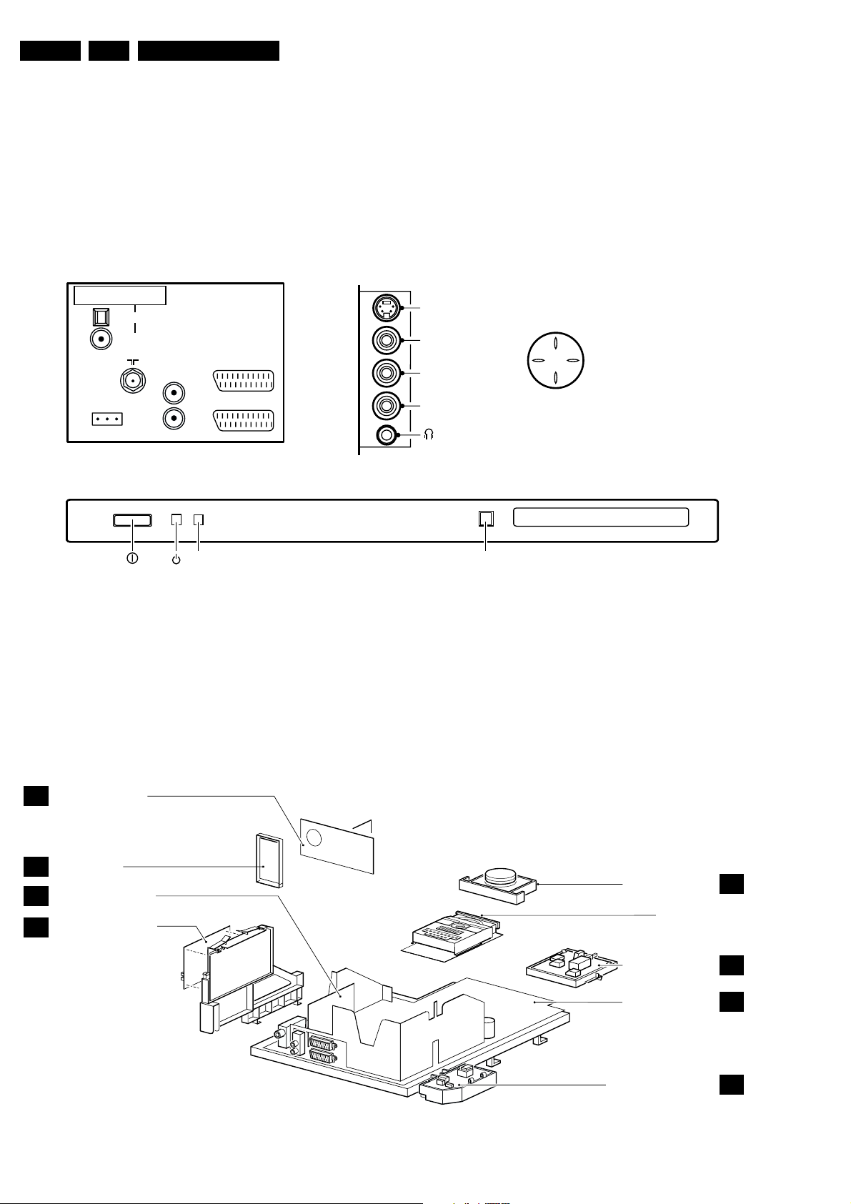
1.2 Connection Facilities
SIDE I/OREAR CONNECTIONS TOP CONTROL
DIGITAL AUDIO OUT
PCM/MPEG2/DOLBY D/DTS
OPTICAL
COAXIAL
AUDIO
ComPair
CONNECTOR
L
R
OUT
EXT. 2
EXT. 1
S-Video
Video IN
L
Audio
R
P+
V+V-
P-
FRONT CONTROL
IR
RED
1.2.1 Cinch - Digital Output
CDDA/LPCM : according IEC958
MPEG1/2, AC3, DTS : according IEC1937
: Digital output swing
is 5Vpp.
1.3 Chassis Overview
CRT/SCAVEM PANEL
B
SIDE I/O PANEL
D
SMALL SIGNAL BOARD
C
DVD INTERFACE PANEL
I
EJECT
DVD-TRAY
CL 16532021_009.eps
060401
TOP CONTROL PANEL
(See service manual DVD-ASD1 3122 785 10840)
DVD MODULE
E
MAINS SWITCH PANEL
LARGE SIGNAL PANEL
MAINS HARMONIC PANEL
CL 16532021_010.eps
J/Q
A
M
060401
Page 3
Safety & Maintenance Instructions, Warnings And Notes
2. Safety & Maintenance Instructions, Warnings And Notes
GB 3A10E-DVD 2.
2.1 Safety Instructions For Repairs
Safety regulations require that during a repair:
• Safety components, indicated by the symbol
be replaced by components identical to the original ones;
• When replacing the CRT, safety goggles must be worn.
Safety regulations require that after a repair, the set must be
returned in its original condition. In particular attention should
be paid to the following points:
• General repair instruction: as a strict precaution, we
advise you to resolder the solder joints, through which
the horizontal deflection current is flowing, in particular:
– All pins of the line output transformer (LOT);
– Fly-back capacitor(s);
– S-correction capacitor(s);
– Line output transistor;
– Pins of the connector with wires to the deflection coil;
– Other components through which the deflection
current flows.
Note: This resoldering is advised to prevent bad connections
due to metal fatigue in solder joints and is therefore only
necessary for television sets older than 2 years.
• The wire trees and EHT cable should be routed correctly
and fixed with the mounted cable clamps.
• The insulation of the mains lead should be checked for
external damage.
• The mains lead strain relief should be checked for its
function in order to avoid touching the CRT, hot
components or heat sinks.
• The electrical DC resistance between the mains plug and
the secondary side should be checked (only for sets
which have a mains isolated power supply). This check
can be done as follows:
– Unplug the mains cord and connect a wire between
the two pins of the mains plug;
– Set the mains switch to the 'ON' position (keep the
mains cord unplugged!);
– Measure the resistance value between the pins of
the mains plug and the metal shielding of the tuner or
the aerial connection on the set. The reading should
be between 4.5 M
– Switch off the TV and remove the wire between the
two pins of the mains plug.
• The cabinet should be checked for defects to avoid
touching of any inner parts by the customer.
Ω and 12 MΩ.
2.2 Maintenance Instructions
It is recommended to have a maintenance inspection carried
out by a qualified service employee. The interval depends on
the usage conditions:
• When the set is used under normal circumstances, for
example in a living room, the recommended interval is 3
to 5 years.
• When the set is used in circumstances with higher dust,
grease or moisture levels, for example in a kitchen, the
recommended interval is 1 year.
• The maintenance inspection contains the following
actions:
– Execute the above-mentioned 'general repair
instruction'.
– Clean the power supply and deflection circuitry on
the chassis.
– Clean the picture tube panel and the neck of the
picture tube.
, should
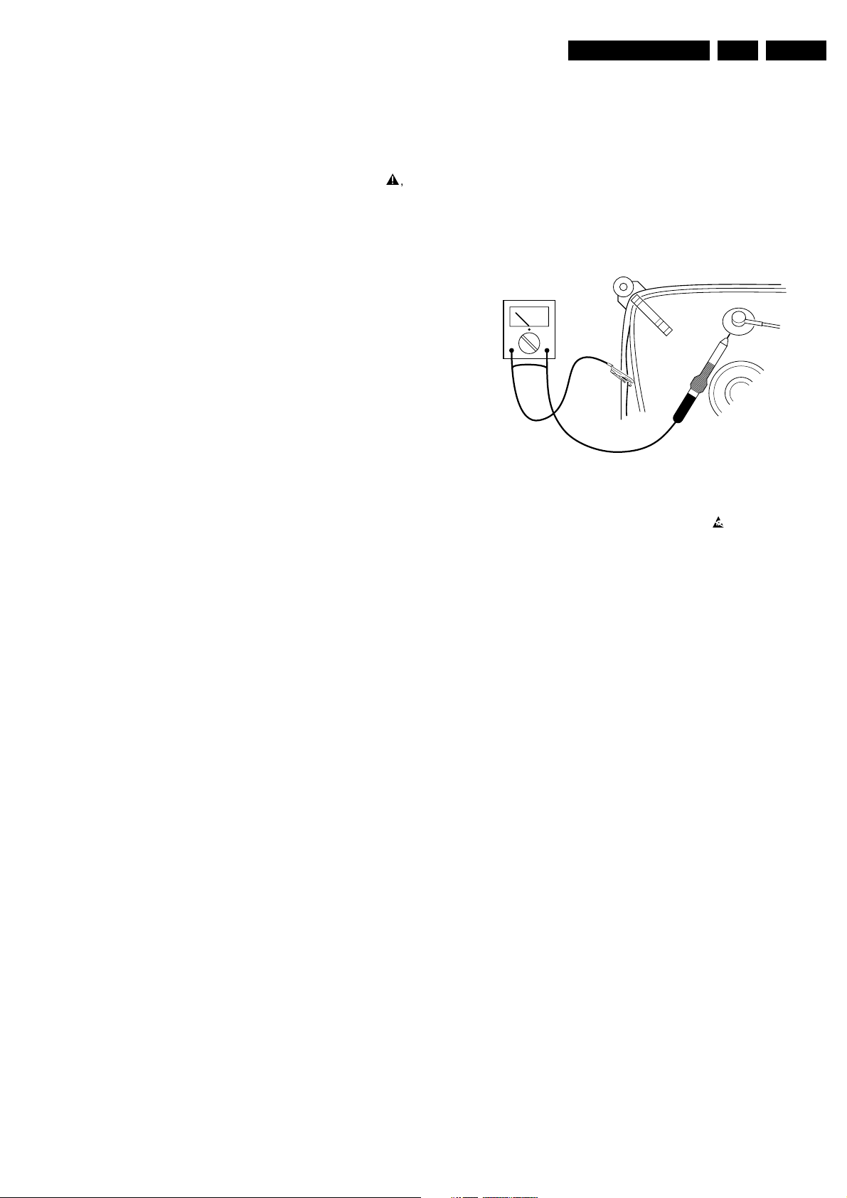
2.3 Warnings
• In order to prevent damage to IC's and transistors, all
high-voltage flashovers must be avoided. In order to
prevent damage to the picture tube, the method shown in
Fig. 2-1 should be used to discharge the picture tube.
Use a high-voltage probe and a multimeter (position
VDC). Discharge until the meter reading is 0 V (after
approx. 30 s).
V
Figure 2-1
• All IC's and many other semiconductors are susceptible
to electrostatic discharges (ESD)
during repair can reduce life drastically. When repairing,
make sure that you are connected with the same
potential as the mass of the set by a wristband with
resistance. Keep components and tools also at this same
potential.
Available ESD protection equipment:
– Complete kit ESD3 (small table mat, wristband,
connection box, extension cable and earth cable)
4822 310 10671.
– Wristband tester 4822 344 13999.
• Together with the deflection unit and any multipole unit,
the used flat square picture tubes form an integrated unit.
The deflection and the multipole units are set optimally at
the factory. Adjustment of this unit during repair is
therefore not recommended.
• Be careful during measurements in the high-voltage
section and on the picture tube.
• Never replace modules or other components while the
unit is switched ON.
• When making settings, use plastic rather than metal
tools. This will prevent any short circuits and the danger
of a circuit becoming unstable.
. Careless handling
CL 26532098/042
140792
Page 4
GB 4 A10E-DVD2.
2.4 Notes
• The direct voltages and oscillograms should be
measured with regard to the tuner earth (
) as this is called.
(
• The direct voltages and oscillograms shown in the
diagrams are indicative and should be measured in the
Service Default Mode (see chapter 5) with a colour bar
signal and stereo sound (L: 3 kHz, R: 1 kHz unless stated
otherwise) and picture carrier at 475.25 MHz.
• Where necessary, the oscillograms and direct voltages
are measured with (
Voltages in the power supply section are measured both
for normal operation (
values are indicated by means of the appropriate
symbols.
• The picture tube PWB has printed spark gaps. Each
spark gap is connected between an electrode of the
picture tube and the Aquadag coating.
• The semiconductors indicated in the circuit diagram and
in the parts lists are completely interchangeable per
position with the semiconductors in the unit, irrespective
of the type indication on these semiconductors.
• DOLBY, the double D symbol and PRO LOGIC are
trademarks of Dolby Laboratories Licensing Corporation.
Manufactured under license from Dolby Laboratories
Licensing Corporation.
) and without () aerial signal.
) and in Standby (). These
Safety & Maintenance Instructions, Warnings And Notes
), or hot earth
Page 5
Safety & Maintenance Instructions, Warnings And Notes
GB
WARNING
All ICs and many other semi-conductors are
susceptible to electrostatic discharges (ESD).
Careless handling during repair can reduce
life drastically.
When repairing, make sure that you are
connected with the same potential as the
mass of the set via a wrist wrap with
resistance.
Keep components and tools also at this
potential.
F
ATTENTION
D
WARNUNG
GB 5A10E-DVD 2.
NL
Alle IC’s en vele andere halfgeleiders zijn
gevoelig voor elektrostatische ontladingen
(ESD).
Onzorgvuldig behandelen tijdens reparatie
kan de levensduur drastisch doen
verminderen.
Zorg ervoor dat u tijdens reparatie via een
polsband met weerstand verbonden bent met
hetzelfde potentiaal als de massa van het
apparaat.
Houd componenten en hulpmiddelen ook op
ditzelfde potentiaal.
I
WAARSCHUWING
AVVERTIMENTO
Tous les IC et beaucoup d’autres semiconducteurs sont sensibles aux décharges
statiques (ESD).
Leur longévité pourrait être considérablement
écourtée par le fait qu’aucune précaution
n’est prise a leur manipulation.
Lors de réparations, s’assurer de bien être
relié au même potentiel que la masse de
l’appareil et enfiler le bracelet serti d’une
résistance de sécurité.
Veiller a ce que les composants ainsi que les
outils que l’on utilise soient également a ce
potentiel.
Alle IC und viele andere Halbleiter sind
empfindlich gegen elektrostatische
Entladungen (ESD).
Unsorgfältige Behandlung bei der Reparatur
kann die Lebensdauer drastisch vermindern.
Sorgen sie dafür, das Sie im Reparaturfall
über ein Pulsarmband mit Widerstand mit
dem Massepotential des Gerätes verbunden
sind.
Halten Sie Bauteile und Hilfsmittel ebenfalls
auf diesem Potential.
GB
Safety regulations require that the set be restored to its original condition
and that parts which are identical with those specified be used.
NL
Veiligheidsbepalingen vereisen, dat het apparaat in zijn oorspronkelijke
toestand wordt terug gebracht en dat onderdelen, identiek aan de
gespecifieerde worden toegepast.
F
Les normes de sécurité exigent que l’appareil soit remis a l’état d’origine et
que soient utilisées les pièces de rechange identiques à celles spécifiées.
Tutti IC e parecchi semi-conduttori sono
sensibili alle scariche statiche (ESD).
La loro longevita potrebbe essere fortemente
ridatta in caso di non osservazione della piu
grande cauzione alla loro manipolazione.
Durante le riparazioni occorre quindi essere
collegato allo stesso potenziale che quello
della massa dell’apparecchio tramite un
braccialetto a resistenza.
Assicurarsi che i componenti e anche gli
utensili con quali si lavora siano anche a
questo potenziale.
D
Bei jeder Reparatur sind die geltenden Sicherheitsvorschriften zu beachten.
Der Originalzustand des Gerats darf nicht verandert werden.
Fur Reparaturen sind Original-Ersatzteile zu verwenden.
I
Le norme di sicurezza esigono che l’apparecchio venga rimesso nelle
condizioni originali e che siano utilizzati pezzi di ricambiago idetici a quelli
specificati.
SHOCK, FIRE HAZARD SERVICE TEST:
CAUTION: After servicing this appliance and prior to returning to customer, measure the resistance between
either primary AC cord connector pins (with unit NOT connected to AC mains and its Power switch ON), and the
face or Front Panel of product and controls and chassis bottom,
Any resistance measurement less than 1 Megohms should cause unit to be repaired or corrected before AC
power is applied, and verified before return to user/customer.
Ref.UL Standard NO.1492.
NOTE ON SAFETY:
Symbol
: Fire or electrical shock hazard. Only original parts should be used to replace any part with symbol
Any other component substitution(other than original type), may increase risk or fire or electrical shock hazard.
“Pour votre sécurité, ces documents
doivent être utilisés par des
spécialistes agrées, seuls habilités à
réparer votre appareil en panne.”
CL 96532065_002.eps
120799
Page 6

GB 6 A10E-DVD2.
Safety & Maintenance Instructions, Warnings And Notes
LASER SAFETY
This unit employs a laser. Only a qualified service person should remove the cover or attempt to service this
device, due to possible eye injury.
LASER DEVICE UNIT
Type: Semiconductor laser GaAlAs
Wave length: 650 nm (DVD)
780 nm (VCD/CD)
Output Power: 7 mW (DVD)
10 mW (VCD/CD)
Beam divergence: 60 degree
USE OF CONTROLS OR ADJUSTMENTS OR PERFORMANCE OF PROCEDURE OTHER THAN THOSE
SPECIFIED HEREIN MAY RESULT IN HAZARDOUS RADIATION EXPOSURE.
AVOID DIRECT EXPOSURE TO BEAM
WARNING
The use of optical instruments with this product will increase eye hazard.
Repair handling should take place as much as possible with a disc loaded inside the player
WARNING LOCATION: INSIDE ON LASER COVERSHIELD
CAUTION VISIBLE AND INVISIBLE LASER RADIATION WHEN OPEN AVOID EXPOSURE TO BEAM
ADVARSEL SYNLIG OG USYNLIG LASERSTRÅLING VED ÅBNING UNDGÅ UDSÆTTELSE FOR STRÅLING
ADVARSEL SYNLIG OG USYNLIG LASERSTRÅLING NÅR DEKSEL ÅPNES UNNGÅ EKSPONERING FOR STRÅLEN
VARNING SYNLIG OCH OSYNLIG LASERSTRÅLNING NÄR DENNA DEL ÄR ÖPPNAD BETRAKTA EJ STRÅLEN
VARO! AVATT AESSA OLET ALTTIINA NÄKYVÄLLE JA NÄKYMÄTTÖMÄLLE LASER SÄTEILYLLE. ÄLÄ KATSO SÄTEESEEN
VORSICHT SICHTBARE UND UNSICHTBARE LASERSTRAHLUNG WENN ABDECKUNG GEÖFFNET NICHT DEM STRAHL AUSSETSEN
DANGER VISIBLE AND INVISIBLE LASER RADIATI ON WHEN OPEN AVOID DIRECT EXPOSURE TO BEAM
AT TENTION RAYO NNEMENT LASER VISIBLE ET INVISIBLE EN CAS D'OUVERTURE EXPOSITION DANGEREUSE AU FAISCEAU
!
CL 06532065_051.eps
230500
Page 7
3. Directions For Use
The television set has 4 keys which are
located on the top of the set.
The VOLUME - + (-
”
+) keys are used to
adjust sound levels.
The PROGRAM - + (- P +) keys are used to
select the required programmes.
To access the menus, simultaneously hold
down the
”
- and
”
+ keys.The
PROGRAM - + keys may then be used to
select an adjustment and the -
”
+ keys to
make that adjustment.
To exit from the menus, hold down the 2
”
- and
”
+ keys.
Note
: when the CHILD LOCK function is activated,
these keys are unavailable (refer to FEATURES
menu on page 8).
2
&
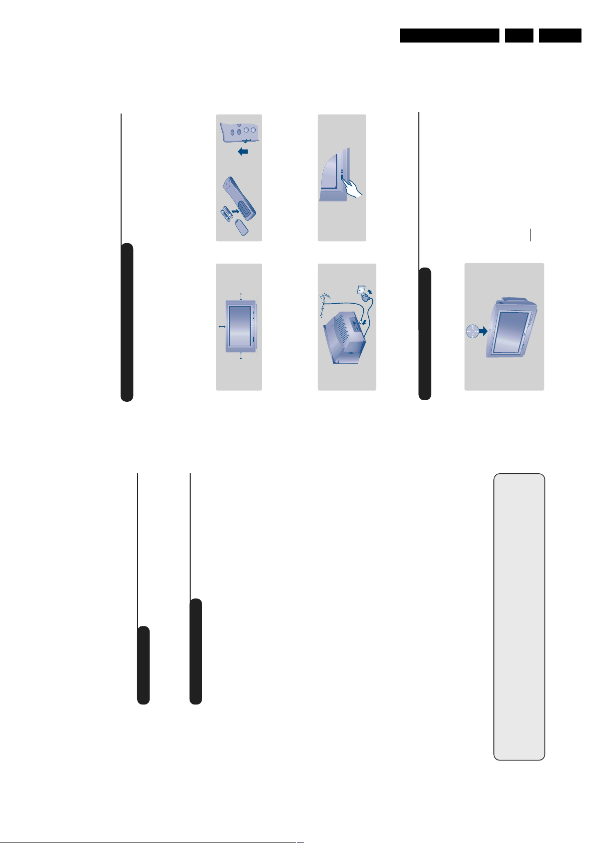
Positioning the television set
Place your TV on a solid, stable surface, leaving
a space of at least 5 cm around the appliance.
To avoid accidents, do not put anything on the
set such as a cloth or cover, a container full of
liquid (vase) or a heat source (lamp).The set
must not be exposed to water.
é
Connections
• Insert the aerial plug into the
:
socket at
the rear of the set.
• Insert the mains plug into a wall socket (220-
240 V / 50 Hz).
“
Remote control
Insert the two R6-type batteries (supplied)
making sure that they are the right way round.
Check that the mode selector is set to TV.
The batteries supplied with this appliance do not
contain mercury or nickel cadmium. If you have
access to a recycling facility, please do not discard
your used batteries (if in doubt, consult your dealer).
When the batteries are replaced, use the same type.
‘
Switching on
To switch on the set, press the on/off key.
A red indicator comes on and the screen
lights up. Go straight to the chapter Quick
installation on page 4.
If the television remains in standby mode,
press P
#
on the remote control.
The indicator will flashe when you use the remote
control.
5 cm
5 cm
5 cm
TV
VCR
DVD
1
4
ı
Ø
`
Installing your television set
The keys on the TV set
Directions For Use
GB 7A10E-DVD 3.
1
Using the built-in DVD player
Inserting a disk . . . . . . . . . . . . . . . . . . . . . . . . . . . . . . . . . . . . . . . . . . . . . . . . . . .12
Playing a DVD or video CD . . . . . . . . . . . . . . . . . . . . . . . . . . . . . . . . . . . . . . . . .13
Playing an audio CD . . . . . . . . . . . . . . . . . . . . . . . . . . . . . . . . . . . . . . . . . . . . . . .14
Using the OSD menu . . . . . . . . . . . . . . . . . . . . . . . . . . . . . . . . . . . . . . . . . . . . . .15
Preferential settings . . . . . . . . . . . . . . . . . . . . . . . . . . . . . . . . . . . . . . . . . . . . . . .16
Favourite tracks . . . . . . . . . . . . . . . . . . . . . . . . . . . . . . . . . . . . . . . . . . . . . . . . . .16
Access control and lock . . . . . . . . . . . . . . . . . . . . . . . . . . . . . . . . . . . . . . . . . . . .17
Play authorisation . . . . . . . . . . . . . . . . . . . . . . . . . . . . . . . . . . . . . . . . . . . . . . . . .17
Peripherals
Video recorder and other equipment . . . . . . . . . . . . . . . . . . . . . . . . . . . . . . . . .18
To select connected equipment . . . . . . . . . . . . . . . . . . . . . . . . . . . . . . . . . . . . .18
TV / VCR / DVD mode selector . . . . . . . . . . . . . . . . . . . . . . . . . . . . . . . . . . . . . .19
Practical information
Tips . . . . . . . . . . . . . . . . . . . . . . . . . . . . . . . . . . . . . . . . . . . . . . . . . . . . . . . . . . . .20
Recycling
Glossary . . . . . . . . . . . . . . . . . . . . . . . . . . . . . . . . . . . . . . . . . . . . . . . . . . . . . . . .20
The materials used in your set are either reusable or can be recycled.
To minimise environmental waste, specialist companies collect used appliances
and dismantle them after retrieving any materials that can be used again (ask
your dealer for further details).
Introduction
Thank you for purchasing this television set.
This handbook has been designed to help you install and operate your TV set.
We would strongly recommend that you read it thoroughly.
We hope our technology meets entirely with your satisfaction.
Installation
Installing your television set . . . . . . . . . . . . . . . . . . . . . . . . . . . . . . . . . . . . . . . . . .2
Table of Contents
The keys on the TV set . . . . . . . . . . . . . . . . . . . . . . . . . . . . . . . . . . . . . . . . . . . . . .2
The remote control keys . . . . . . . . . . . . . . . . . . . . . . . . . . . . . . . . . . . . . . . . . . . .3
Quick installation . . . . . . . . . . . . . . . . . . . . . . . . . . . . . . . . . . . . . . . . . . . . . . . . . .4
Sorting programmes . . . . . . . . . . . . . . . . . . . . . . . . . . . . . . . . . . . . . . . . . . . . . . . .4
Using other TV menus . . . . . . . . . . . . . . . . . . . . . . . . . . . . . . . . . . . . . . . . . . . . . .5
Choosing a language and country . . . . . . . . . . . . . . . . . . . . . . . . . . . . . . . . . . . . .5
Automatic tuning . . . . . . . . . . . . . . . . . . . . . . . . . . . . . . . . . . . . . . . . . . . . . . . . . .5
Manual tuning . . . . . . . . . . . . . . . . . . . . . . . . . . . . . . . . . . . . . . . . . . . . . . . . . . . . .6
Programme name . . . . . . . . . . . . . . . . . . . . . . . . . . . . . . . . . . . . . . . . . . . . . . . . . .6
Operation
Adjusting the picture and the sound . . . . . . . . . . . . . . . . . . . . . . . . . . . . . . . . . . .7
Rotating the picture . . . . . . . . . . . . . . . . . . . . . . . . . . . . . . . . . . . . . . . . . . . . . . . .7
Timer function . . . . . . . . . . . . . . . . . . . . . . . . . . . . . . . . . . . . . . . . . . . . . . . . . . . .8
Locking the set . . . . . . . . . . . . . . . . . . . . . . . . . . . . . . . . . . . . . . . . . . . . . . . . . . . .8
Teletext . . . . . . . . . . . . . . . . . . . . . . . . . . . . . . . . . . . . . . . . . . . . . . . . . . . . . . . . . .9
16:9 Formats . . . . . . . . . . . . . . . . . . . . . . . . . . . . . . . . . . . . . . . . . . . . . . . . . . . . .10
°
Page 8
GB 8 A10E-DVD3.
4
Quick installation
Sorting programmes
The first time you switch on the television, a
menu appears on the screen and the tuning
starts automatically.
If the menu does not appear, hold down the
”
-
and
”
+ keys on the set for 5 seconds to start
the tuning.
The operation takes several minutes.
A display shows the search status and the
number of programmes found.When it has
finished the menu disappears.
To exit or interrupt the search, press the
H
key.
If no programmes are found, refer to the chapter
entitled Tips on p. 16.
& If the transmitter or the cable network
broadcasts the automatic sort signal, the
programmes will be correctly numbered.
é If not, the programmes found will be
numbered in descending order starting at 99,
98, 97,etc.
Use the SORT menu to renumber them.
Some transmitters or cable networks broadcast
their own sort parameters (region, language, etc.).
Where this is the case, make your choice using the
IJ
keys and confirm with
L
.
& Press the
H
key. The main menu is displayed.
é Select INSTALL (
J
), then press
L
.
The INSTALL menu appears.
“ Using the
J
key, select SORT then press
L
.
The SORT menu appears.The FROM option is
activated.
Note:
this menu works as follows:
• Change "FROM" (enter the current programme
number),
• "TO" (enter the new number),
• EXCHANGE numbers" (the operation is carried out).
‘ Select the programme you wish to renumber
using
KL
keys or
0
to
9
.
Example: to renumber programme 78 as 2
press
78
.
( Select TO (using
J
key) and enter the new
number with
KL
keys or
0
to
9
(for the
example given, enter
2
).
§ Select EXCHANGE (
J
key) and press
L
.
The message EXCHANGED appears, the
exchange takes place. In our example,
programme 78 is renumbered as 2 (and
programme 2 as 78).
è Select the option FROM (
I
key) and repeat
stages ‘ to § as many times as there are
programmes to renumber.
! To exit from the menus,press
R
.
• PICTURE
• SOUND
• FEATURES
• INSTALL
INSTALL
• LANGUAGE
• COUNTRY
• AUTO STORE
• MANUAL STORE
• SORT
• NAME
FROMTOEXCHANGE
SELECT LANGUAGE
LANGUAGE
•
ENGLISH
DANSK
NEDERLANDS
FINNISH
FRANCAIS
COUNTRY
AUSTRIA
BELGIUM
SWITZERLAND
GERMANY
DENMARK
SEARCHING
PLEASE WAIT
PROG. NO. 2
215.18 MHZ
Directions For Use
Contrast +
To activate / de-activate the
automatic contrast adjustment
List of programmes
to select a
to display it.
IJ
L
Use the keys
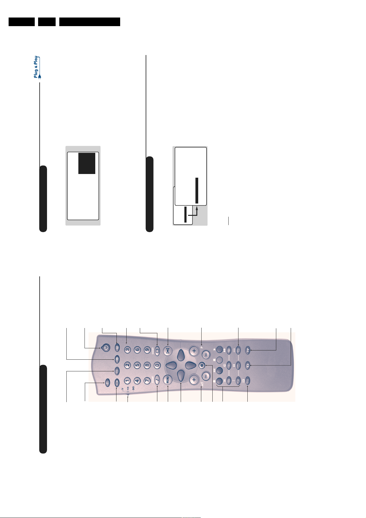
The remote control keys
To display /clear the list of programmes.
programme and the key
.
09
or
@#
system (the dark areas are made
darker whilst maintaining the detail).
Standby
To set the TV to standby mode.
To switch the TV set on again,
press P
Key not used
Sleeptimer
is displayed alongside
if they are not locked.
+
?
or
The symbol
all programmes which are locked (p.8)
240 minutes)
To select the length of time
before the set automatically
switches to standby (from 0 to
digit must be entered
nd
Numerical keys
For direct access to programmes.
For a 2 digit programme number,
the 2
before the dash disappears.
and S-VHS3.
Select EXT sockets
Press several times to select
EXT1, EXT2 and EXT3,S-VHS2
Smart picture controls
Mode selector (p. 15)
To activate the remote control
To access a series of settings: RICH,
NATURAL,SOFT,MULTIMEDIA
and return to PERSONAL.
Surround sound
DVD mode (p.12).
Smart sound controls
To access a series of settings:
in TV,VCR (video recorder) or
deactivate the surround
/
To activate
sound effect. In stereo, this gives the
impression that the speakers are further
apart. For models equipped with Virtual
Dolby Surround*,you can obtain Dolby
Menu
return to PERSONAL
VOICE, MUSIC,THEATRE and
To display or exit from the menus
Surround Pro Logic sound quality. In
mono,a stereo spatial effect is simulated.
* Manufactured under license from Dolby
Laboratories Licensing Corporation. ”Dolby””Pro Logic”
Cursor
within the menus or to have
These 4 keys are used to move
direct access to the 16:9 formats
are trademarks of
£
Selecting TV programmes
To move up or down a programme.
Dolby Laboratories Licensing Corporation.
and the double-D symbol
(p 10).
Vol u me
To adjust the sound level
The number,(the name) and the sound
mode are displayed for a few seconds.
For some TV programmes the title of
the programme appears at the
bottom of the screen.
Screen information
To display / remove the programme
number,the name (if it exists), the
Mute
Sound mode
or DVD mode (p.12)
Teletext features (p. 9)
To disable or enable the sound.
To switch from STEREO to
time, the sound mode and the time
remaining on the timer. Hold down
for 5 seconds to permanently
display the programme number on
the screen.The volume level and the
smart control adjustments are then
displayed each time they are used.
Dual I and Dual II for
bilingual transmissions.
MONO or to choose between
For TV sets fitted with NIC AM
NICAM DUAL I, NICAM
from NICAM STEREO to
reception, depending on the
MONO or choose between
transmission, you can switch
3
Previous programme
To access the previously viewed
programme.
16:9 formats (p. 10)
displayed in red.
DUAL II and MONO.
to MONO, the indication is
When the sound mode is switched
Page 9
Directions For Use
6
Manual tuning
Programme name
This menu allows you to store the
programmes one by one.
& Press
H
.
é Select INSTALL (
J
), then press
L
.
The INSTALL menu appears.
“ Select MANUAL STORE (
J
) then press
L
.
The menu appears :
‘ Press
L
to go to the SYSTEM menu.
Use
IJ
to choose EUROPE (automatic
detection*) or manual detection with WEST
EUR (standard BG reception), EAST EUR
(standard DK reception), UK (standard I
reception) or FRANCE (standard LL').
Then press
K
to exit from the menu.
* Except for France (standard LL'): select the
option FRANCE.
( Select SEARCH and press
L
.
The search begins.As soon as a programme is
found, the search will stop. If you know the
frequency of the programme required,enter
its number directly using the
09
keys and
go to step è.
If no programme is found, refer to the Tips chapter
on page 16).
§ If reception is un-satisfactory, select FINE
TUNE and hold down
K
or
L
key.
è Select PROG. NO (programme number) and
use the
KL
or
0
to
9
keys to enter the
desired number.
! Select STORE and press
L
.The message
STORED appears.The programme is stored.
ç Repeat steps ( to ! for each programme to
be stored.
To exit: press the
R
key.
You may, if you wish, give a name to the first
40 programmes (from 1 to 40).
& Press
H
.
é Select INSTALL (
J
), then press
L
.
The INSTALL menu appears.
“ Press
J
5 times to select NAME (concealed
at the bottom of the screen), then press
L
.
The menu appears :
‘ Select the programme you wish to name using
the keys
09
or
@
P
#
.
Note:
at the time of installation, the programmes
are automatically named when the identification
signal is transmitted.
( Use the keys
KL
to move within the name
display area (5 characters).
§ Use keys
IJ
to choose the characters.
è Press
H
when the name has been entered.
The programme name is stored.
! Repeat steps ‘ to è for each programme to
be named.
ç To exit from the menus,press
R
.
• PICTURE
• SOUND
• FEATURES
• INSTALL
INSTALL
MANUAL STORE
• SYSTEM
• SEARCH
• PROG. NO.
• FINE TUNE
• STORE
EUROPE
WEST EUR
EAST EURUKFRANCE
INSTALL
• LANGUAGE
• COUNTRY
• AUTO STORE
• MANUAL STORE
• SORT
•
NAME
BBC_1
TV
VCR
DVD
1
4
`
ıØ
MENU MENU MENU
GB 9A10E-DVD 3.
Using other menus
PICTURE
• BRIGHTNESS
• COLOUR
• CONTRAST --I------ 39
• SHARPNESS
• STORE
keys.
IJ
to go into the LANGUAGE menu.
L
‘ Select your language with the
“ Press
.
L
), then press
J
key to display the main menu.
H
Choosing a language and country
é Select INSTALL (
& Press the
.
L
keys.
IJ
to exit the LANGUAGE menu.
K
The menus will appear in the chosen language.
The INSTALL menu appears.
If your country does not appear in the list, select
OTHER.
è Select your country with
( Press
§ Select the option COUNTRY and press
ENGLISH
DANSK
INSTALL
• LANGUAGE
• COUNTRY
• PICTURE
• SOUND
• FEATURES
• INSTALL
The LANGUAGE option is activated.
.
R
to exit the COUNTRY menu.
K
! Press
ç To exit from the menus,press
NEDERLANDS
• AUTO STORE
• MANUAL STORE
NAME
• SORT
•
Automatic tuning
broadcasts the automatic sort signal, the
“ If the transmitter or the cable network
This menu allows you to automatically search
for all the programmes available in your region
programmes will be correctly numbered.
‘ If not, the programmes found will be
(or on your cable network).
& First carr y out operations & to ! above,then:
numbered in descending order starting at 99,
98, 97,etc.
Use the SORT menu to renumber them.
.The search begins.
once to select AUTO STORE then
J
L
press
After several minutes, the INSTALL menu
é Press
.
L
keys and confirm with
IJ
Some transmitters or cable networks broadcast
their own sort parameters (region, language, etc.).
Where this is the case, make your choice using the
INSTALL
• LANGUAGE
reappears automatically.
key. If
H
.
R
no picture is found, refer to the chapter entitled
Tips on p. 16.
To exit or interrupt the search, press the
( To exit from the menus,press
SEARCHING
PLEASE WAIT
PROG. NO. 2
215.18 MHZ
NAME
• COUNTRY
• AUTO STORE
• MANUAL STORE
• SORT
•
5
Page 10

GB 10 A10E-DVD3.
8
Timer function
Locking the set
This menu allows you to use your TV as an
alarm clock.
& Press
H
.
é Select FEATURES (
J
) and press
L
twice.
The TIMER menu appears :
“ Press
L
to enter and exit the sub-menus and
use keys
IJ
to adjust:
‘ TIME: enter current time.
Note:
the time is updated automatically each time
the set is switched on using teletext information
taken from programme 1. If programme 1 does
not have teletext, the update will not take place.
( START TIME: enter the start time.
§ STOP TIME: enter the stop time.
è PROG; NO;:enter the number of the
programme required.
! ACTIVATE: you can set the alarm to be
activated:
• ONCE ONLY for a one-off alarm,
• DAILY for a daily alarm or
• STOP to cancel.
ç Press
R
to set the TV to standby. It will
automatically switch on at the time
programmed. If you leave the TV switched on,
it will only change programme at the time
indicated.
You can bar access to certain programmes or
completely lock the set by locking the keys.
Locking programmes
& Press
H
.
é Select FEATURES (
J
) and press
L
.
“ Select PARENTAL.CONT. (
J
) and press
L
.
‘ Enter your confidential access code. The first
time, enter the code 0711 then confirm by
re-entering 0711.The menu appears.
( Press
L
to go into the menu.
§ Use keys
IJ
to select the required
programme and confirm with
L
.The symbol
+
is displayed alongside the programmes or
sockets that have been locked.
è Press
R
to exit.
To watch a programme which has been locked
you will now need to enter the confidential
code; otherwise the screen will remain blank.
The INSTALL menu access is also locked.
Caution:
in the case of encrypted programmes
which use an external decoder, it is necessar y to
lock the corresponding EXT socket.
To unlock all programmes
Repeat stages & to ‘ above, then select
CLEAR ALL and press
L
.
To change the confidential code
Repeat stages & to ‘ above, then:
( Select CHANGE CODE and enter your own
4-digit number.
§ Confirm by entering it again.
Your new code will be stored.
è Press
R
to exit from the menus.
If you have forgotten your confidential code, enter
the universal code 0711 twice.
Locking the keys
& Press
H
, select FEATURES (
J
) and press
L
.
é Select CHILD LOCK (
J
) and press
L
to set
the lock to ON.
“ Switch off the set and put the remote control
out of sight.
The set cannot be used (it can only be
switched on using the remote control).
‘ To cancel:switch CHILD LOCK to OFF.
• PICTURE
• SOUND
• FEATURES
• INSTALL
FEATURES
TIMER
• TIME
• START TIME
• STOP TIME
• PROG; NO;
• ACTIVATE
10:56
• PICTURE
• SOUND
• FEATURES
• INSTALL
FEATURES
• TIMER
• CHILD LOCK
• PARENTAL CONT
• ROTATION
ACCES CODE
- - - -
w
Check that the mode selector on the side of the remote control is set to TV.
Directions For Use
Check that the mode selector on the side of the remote control is set to TV.
w
image.
• BRIGHTNESS: alters the brightness of the
light and dark tones.
• COLOUR: alters the colour intensity.
• CONTRAST: alters the variation between
Description of the settings:
--I------ 39
.
L
PICTURE
• BRIGHTNESS
• COLOUR
• PICTURE
• SOUND
• FEATURES
• INSTALL
• CONTRAST
Adjusting the picture
then
H
& Press
The PICTURE menu appears :
SHARPNESS: alters the crispness of the image.
• STORE:stores the picture settings.
• COLOUR TEMP (colour temperature):
•
• SHARPNESS
• STORE
• COLOUR TEMP.
• NR
adjusts the colour temperature of the
picture.Three options are available here:
COOL (blue white), NORMAL (balanced) or
WARM (red white).
(snowy picture).This setting is useful when
reception is difficult.
versions): optimizes the quality of the picture
• ACTIVE CONTROL (only available on certain
according to the quality of reception.
• NR (Noise Reduction): alleviates fuzziness
L
KL
.
R
held down to access the settings
J
keys to select a setting and
the menu is a scroll-down menu.
IJ
hidden at the bottom of the screen.
keys to adjust.
é Use
Note:
made, select the option STORE and press
“ Once the necessar y adjustments have been
to store them.
‘ To exit from the menus,press
Keep the key
This adjustment is in the OPTIONS menu.
sound.
sound.
• BASS: alters the levelof the low frequency
• BALANCE: to balance the sound between
the left and right speakers.
• TREBLE: alters the levelof the high frequency
Description of the settings:
) and
J
-----I--- 56
SOUND
• TREBLE
• BASS
• BALANCE
, select the SOUND option (
.The SOUND menu appears :
H
L
Adjusting the sound
& Press
press
• PICTURE
• SOUND
• FEATURES
• INSTALL
you to compensate for the volume differences
between the different programmes or the
EXT sockets.This setting is available for
• DELTA VOLUME (volume difference): allows
programmes 1 - 40 and the EXT sockets.
• DELTA VOLUME
• STORE
• AVL
keys to select a setting and keys
IJ
é Use
volume control used to avoid sudden
increases in volume, particularly when
changing programmes or during
• STORE:stores the sound settings.
• AVL (Automatic Volume Leveller): automatic
L
key.
J
to adjust.
KL
to access the AVL setting (hidden at the
made, select the option STORE and press
Note:
bottom of the screen) hold down
to store them.
“ Once the necessar y adjustments have been
key to select ROTATION and use
advertisements
J
The FEATURES menu appears.
“ Use
(only available on certain versions)
.
R
Larger screens are sensitive to variations in
the earth's magnetic field.This setting makes it
Rotating the picture
‘ To exit from the menus,press
7
to exit from the menus.
keys to alter the angle of the image.
R
KL
‘ Press
.
L
) and press
J
.
H
possible to compensate for this phenomenon.
& Press
é Select FEATURES (
Page 11
Directions For Use
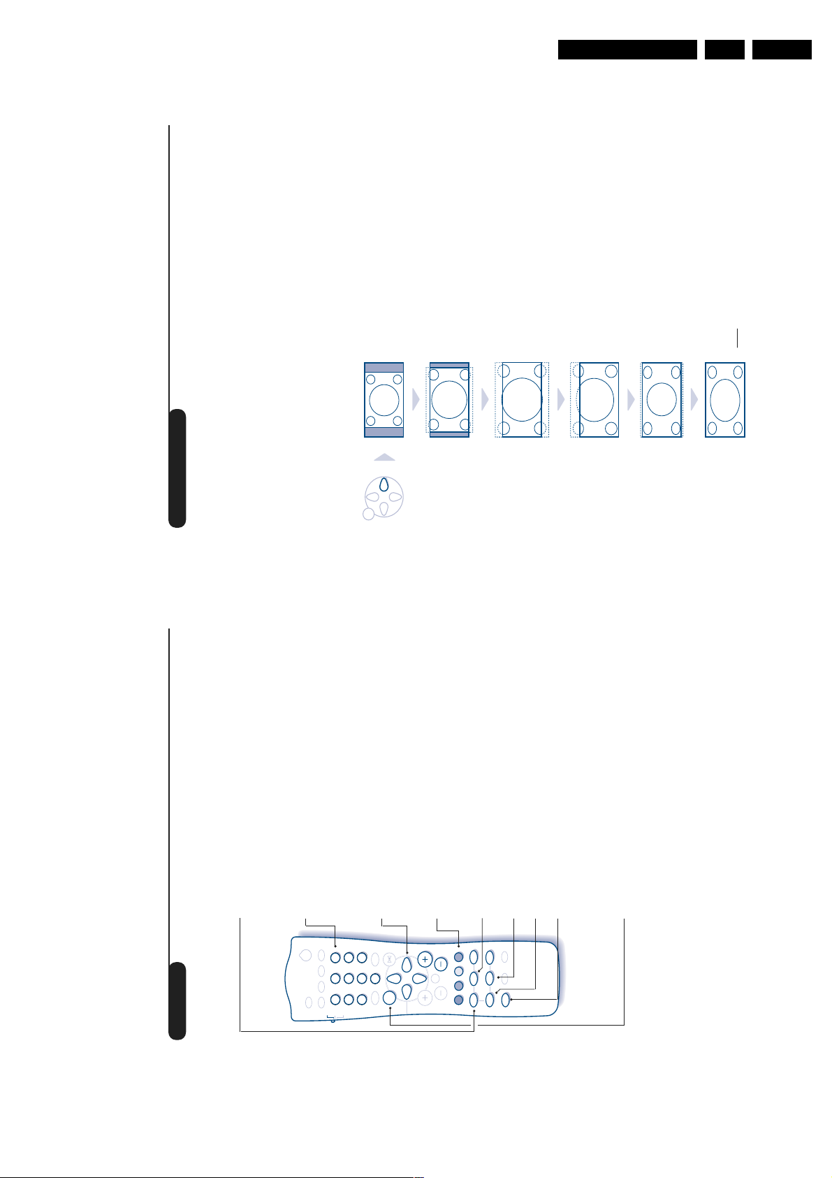
10
16:9 Formats
The pictures you receive may be transmitted in 16:9 format (wide screen) or 4:3 format
(conventional screen). 4:3 pictures sometimes have a black band at the top and bottom of the screen
(letterbox format).This function allows you to optimise the picture display on screen.
Automatic switching
This TV set is also equipped with automatic switching which will select the correct-screen format,
provided the specific signals are transmitted with the programmes.
This automatic format can olso be modified manually.
Using the different screen formats
Press the
L
key (or
K
) to select the different modes:
4:3, ZOOM 14:9,ZOOM 16:9, SUBTITLE ZOOM, SUPER ZOOM and WIDE SCREEN.
You can also access these settings with key
P
.
4:3 Mode
The picture is reproduced in 4:3 format and a black band
is displayed on either side of the picture.The picture may
be progressively enlarged using the
IJ
keys.
ZOOM 14:9 Mode
The picture is enlarged to 14:9 format, a thin black band
remains on both sides of the picture.The
IJ
keys allow
you to compress vertically the image to view the top or
the bottom of the picture (subtitles).
ZOOM 16:9 Mode
The picture is enlarged to 16:9 format.This mode is
recommended when displaying pictures which have black
bands at the top and bottom (letterbox format).
Use the
IJ
keys if you wish to display the top or the
bottom of the picture.
SUBTITLE ZOOM Mode
This mode is used to display 4:3 pictures using the full
surface of the screen leaving the sub-titles visible.
Use the
IJ
keys to increase or decrease the section at
the bottom of the picture.
SUPERWIDE Mode
This mode is used to display 4:3 pictures using the full
surface of the screen by enlarging the sides of the picture.
The
IJ
keys allow you to move the image up or down.
WIDE SCREEN Mode
This mode restores the correct proportions of pictures
transmitted in 16:9 using full screen display.
Note:
If you display a 4:3 picture in thid mode, it will be
enlarged horizontally.
MENU
w
Check that the mode selector on the side of the remote control is set to TV.
GB 11A10E-DVD 3.
Teletext
To call up or exit from teletext.When first pressed, the main index page
Switch teletext on/off
Teletext is an information system, broadcast by certain channels, which can be read like a newspaper. It
also provides subtitles for people with hearing difficulties or those who are unfamiliar with the
language in which a particular programme is being broadcast (cable networks, satellite channels, etc.).
appears with a list of the items available. Each page has a corresponding
3-figure number.
If the selected channel does not broadcast teletext, 100 will appear and the screen
will remain blank (in this case, exit from teletext and choose another channel).
Selecting a teletext page
.
`
.The number is
120
to enter the page number
#
P
@
or
IJ
or
9
to
0
required. For example: for page 120, press
displayed in the top left-hand corner, the page counter starts searching
Use keys
3
|Œ
2
ı
1
Ø
TV
VCR
DVD
to directly
KL
. Use the keys
ÍÆ
or
Í
,
Æ
and the page is displayed.Repeat the procedure to consult another page.
If the counter continues searching, this means that the selected page is not
broadcast. Choose another number.
Direct selection of sub-pages
9
6
ª-
SMART
8
5
0
7
4
SMART
access the sub-pages of your choice.
Coloured zones are displayed at the bottom of the screen. The 4
Certain pages contain sub-pages (for example, page 120 contains sub-pages
1/3, 2/3 and 3/3).If this is the case, the page number is displayed in green,
preceded by the symbol
MENU
coloured keys give access to the corresponding subjects or pages.
Direct access to subject headings
P
Æ
Ê
[
·¢
”
The coloured zones flash when the subject or the page is not yet available.
Press this key to display the upper, then lower part of the screen, and
then to return to the normal page size.
Page enlargement
∫
Á
OSD
Ó
√
∆
%
∏
Ÿ
›
OK
Å
Ω
¤
ù
Use this key to reveal/conceal hidden information (answers to puzzles).
Reveal
Overlaying text on the TV picture
if you want to hold a page (i.e. the contents page).
S
To activate or deactivate screen overlay.
To activate or deactivate the double page teletext display mode.The
active page is displayed on the left and the following page is displayed on
the right. Press
The active page is then displayed on the right.To return to normal
Double page teletext
.
E
For teletext programmes 1 to 40, you can store 4 favourite pages which
mode, press
Favourite pages
you can then access via the coloured keys (red,green, yellow, blue).
.
H
& Press
9
.
H
down for 5 seconds.
R
then the coloured key of your choice.The page is stored.
R
To remove these settings, hold
colour at the bottom of the screen.
To get back to the normal subject headings, press
‘ Repeat steps é and “ for the other coloured keys.
( From now on, when you consult teletext,your favourite pages appear in
é Enter the number of the page required.
“ Press
Page 12

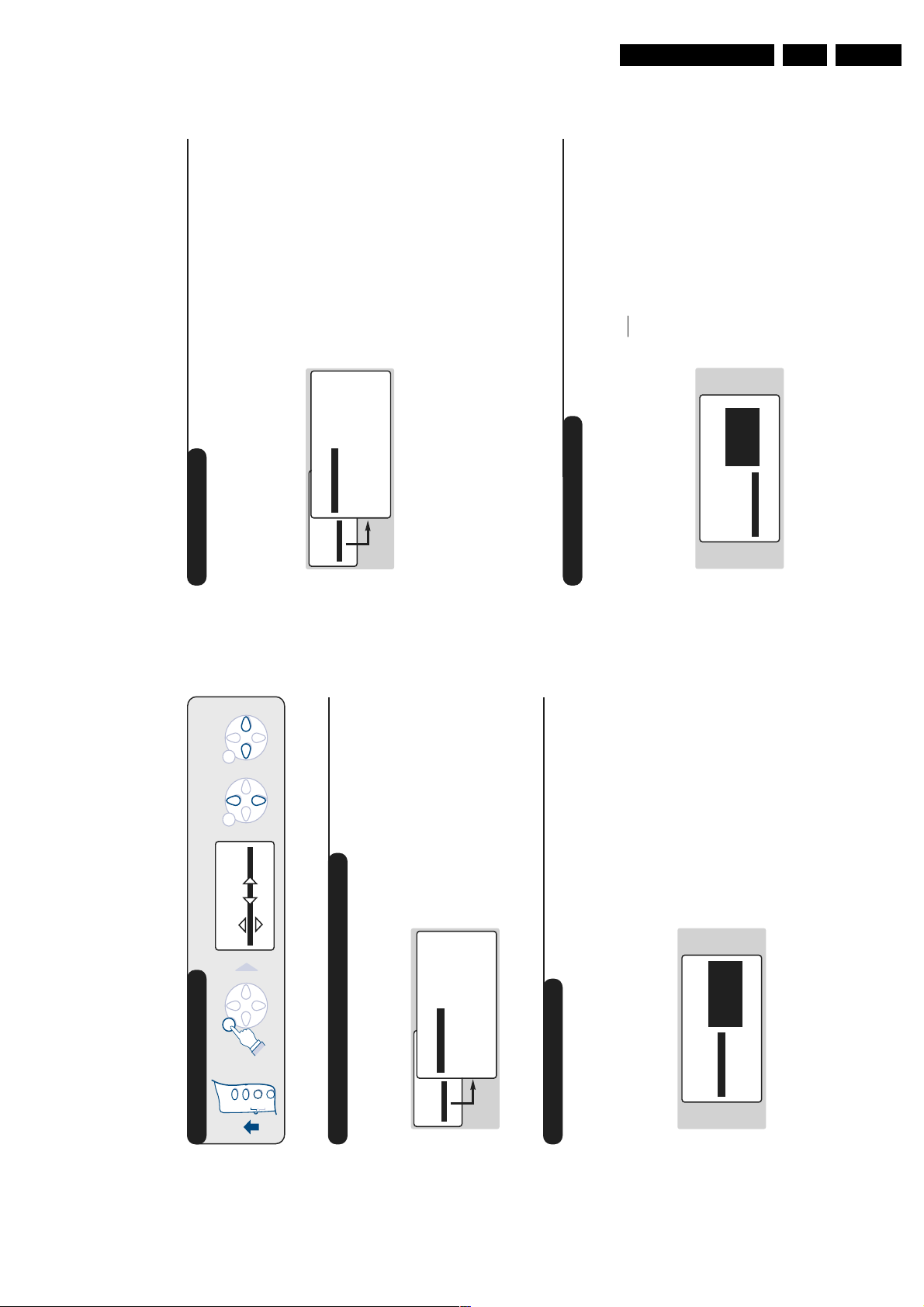
GB 12 A10E-DVD3.
12
Using the built-in DVD player
Inserting a disk
The built-in DVD player allows you to play DVD video disks as well as video and audio CDs
(including finalised CD-Rs and CD-RWs).The disks can be recognised by their logo on the
packaging.
Note:
Generally, DVD films are not placed on the market at the same time in the various regions of the
world. Accordingly, DVD players are provided with geographical zone codes. If you insert a disk which has a
regional code that is different from that of your reader, you will see a message displayed on the screen.The
disk cannot be played and you will have to remove it.
&
Opening the drawer
Press the EJECT button on the front, to the
left of the drawer. The television automatically
switches to DVD mode and the drawer opens.
é
Inserting the disk
Place the disk in the drawer, with the label
facing upwards. Makes sure that it is positioned
correctly in the recess.
“
Closing the drawer
Gently push the drawer back in or press the
EJECT button next to the drawer to close.
The disk will begin to play.
‘
Automatic play
Play begins automatically when the drawer
closes. A status window appears on the left of
the screen and indicates the current operation,
the type of disk and its length. Next,the
content of the disk is displayed.
Directions For Use
Different modes can be selected to suit different picture formats,
use the following diagrams as a guide to which mode to use.
Selecting the correct mode
&
4:3 Picture
ZOOM 14 : 9
There are 5 possible modes for this type of picture
MENU
ZOOM 16 : 9
4 : 3
11
Subtitles
SUBTITLE ZOOM
SUPERWIDE
MENU
ZOOM 16 : 9
x2
WIDE SCREEN
x1
MENU
4 : 3
MENU
Progressive zoom
4:3 Picture Letterbox
é
16:9 Picture
“
4 : 3
Page 13

Directions For Use
14
Playing an audio CD
w
First you must switch the mode selector located on the side of the
remote control to the DVD position.
Play
Once the disk has been inserted and the drawer has closed, play
begins automatically.A special menu appears on the screen, indicating
the number of tracks, the total length of the disk, the current track
and time.
Changing tracks
Use the
@
P
#
keys on the remote control to change tracks or
the
09
keys to select the track of your choice.
Fast forward and rewind
Press the
¢
key or
∫
to fast forward or rewind at x4 or x8
speed. Press
Æ
to return to normal speed.
Pause / stop / eject
Press
∆
to pause and
Æ
to resume play. Press
Ê
to stop and the
EJECT button located on the front of the television to eject the
disk.
Programming a favourite track selection
This function allows you to programme a selection of tracks into the
memory.
& Press
Ê
.
é Use the
J
key to select the trackline.
“ Use the
KL
or
09
keys to choose the number of the required
track.
‘ Press
P
to select it.The chosen number appears at the bottom of
the screen.
( Repeat operations “ and ‘ for each favourite track you wish to
select (maximum of 20 per disk).
If you wish you can repeat the same track number several times.
§ Press
Æ
to begin playing your favourite tracks.
è To stop playing favourite tracks, position the on/off line of the menu
on off (shown in white).
! To delete everything,select Delete all and press
P
.
To delete one track only, simply select its number in the favourites list (at the
bottom of the screen) and press
P
.
”
P
SMART
TV
VCR
DVD
SMART
· ¢
∫
%
Ê
∆
Æ
OK
OSD
.
1
3
2
4
6
5
7
9
8
0
`
ı
Ø
|Œ
ª-
[
›
¤
Å
Ó
√
Ÿ
Ω
ù
∏
Á
MENU
GB 13A10E-DVD 3.
To access the DVD functions you must first switch the mode selector
located on the side of the remote control to the DVD position.
Playing a DVD or video CD
Once the disk has been inserted and the drawer closed, play begins
Play
w
.
|Œ
ı
`
Ø
(button C).
P
button, then when you see the
then press
IJ KL
or
09
button to stop play. The default screen appears and displays
Ê
Press the
information on the player status.
Use the buttons
Stopping play
9
3
6
ª-
SMART
8
5
2
0
7
1
4
SMART
DVD
TV
automatically.Certain disks will ask you to select a heading from a menu.
VCR
Æ
), you can resume play at the exact point
Ê
you stopped the disk. Simply press the
When you stop a disk mid-play (by switching to TV mode, standby,
ejecting the disk or pressing
Re-starting play (“resume” function)
MENU
.
Æ
again (otherwise the disk will start playing
symbol press
Æ
R
symbol (resume),press
from the beginning).
The resume function remenbers the last 4 disks played. Simply re-insert the
disk and when you see the
R
Slow motion, fast forward and rewind
P
Æ
∫
Ó
Ê
%
[
›
·¢
OK
¤
”
) button to fast forward or
to return to normal speed.
Æ
KL
(or
button to slow play down to 1/2,1/4 or 1/8
∫
J
or
¢
During play, press the
rewind at x4 or x32 speed. Press
speed. Press the
Freeze-frame
Á
√
OSD
∆
Ÿ
∏
Ω
Å
ù
again to move to the next
∆
) to freeze the image. Press
I
to resume play.
Æ
(or
∆
frame or
Press
DVD disks are split into different chapters to allow certain scenes to be
Next / previous chapter
keys to access the previous or next
#
P
@
key. The DVD menu appears. Its contents will depend on
H
chapter.
Press the
the DVD. It allows you to access different sections,such as choice of
accessed directly. Use the
language, direct access to certain scenes,special production notes,
DVD menu
exit.
H
confirm and
P
keys to select,
KL IJ
A menu bar appears at the top of the screen, this will disappear after a
Press the E key to select the different languages available on the disk.
trailers, etc.Use the
Language selection
keys to choose your subtitling
IJ
. Use the
L
few seconds.
Press the E key then
Subtitling language
language (choose off to deactivate it).The menu disappears after a few
seconds.
Press the EJECT button located on the front of the television.Play
Ejecting the disk
13
stops, then after several seconds the drawer opens.
Page 14

GB 14 A10E-DVD3.
16
Preferential settings
Press
Q
. On the menu bar,select
A
and
press
J
to display the preferential settings
menu:
Image preferences:
F
You can set:
• TV format; to choose the screen format
(your TV must be set to 16:9),
• Black level shift; to highlight the levels of
black in the image (only works with NTSC
images),
• Video shift; to move the image horizontally.
Sound preferences:
M
• Digital output; allows you to choose: All
(the optical and coaxial outputs are
activated), PCM (the optical and coaxial
outputs are activated, but for the connection
of an appliance without a multichannel digital
decoder) or Off (no output is activated).
• Analog output; to choose the type of
signal available on the analog output: Stereo,
Dolby Surround* or 3D sound*.
* These settings do not wor k with this television.
• Night mode; optimises the sound dynamics
for low-volume listening.
• Karaoke vocal; Only activate this function
for playing special karaoke DVDs (the
karaoke voices on the disk are then mixed
into the normal stereo sound).
Language preference:
N
• Audio language; to define the preferred
language for the soundtracks of DVD films.
• Subtitle; to define the preferred language
for subtitles on DVD films.
If the preferred language is available on the disk,
it will be selected by default. If not, the first
language on the disk will be activated.
• Menu; to set the language for the OSD
menus of the DVD. If your language is not
available, select English.
Display preferences:
O
• Access control (see next page)
• Status window; to turn off the display of
the player’s status window.
• Low-power standby; on a fixed image, the
contrast automatically fades after 5 min.
Favourite tracks
This function allows you to program a
selection of favourite tracks into the memory.
& Press
Q
. On the menu bar,select
G
and
press
J
to display the menu.
é Use the
J
to select the title or chapterline.
“ Use the
KL
or
09
keys to choose the
number of the favourite title or chapter.
‘ Press
P
to select.The chosen number
appears at the bottom of the screen.
( Repeat operations “ and ‘ for each
favourite title or chapter to be selected
(maximum of 20 per disk).
If you wish you can repeat the same track number
several times.
§ Press
Q
to exit.The favourite tracks begin
playing automatically.
To stop playing favourite tracks
Position the on/off line of the menu on off
(shown in white).
To delete all
Select Delete all and press
P
.
To delete one title or track only, simply select its
number in the favourites list (at the bottom of the
screen) and press
P
.
TV Shape 16/9
Black level shift On
Video shift ____.____
Directions For Use
Description of symbols:
This menu allows you to access all the special
OSD menu
Preferential settings
Audio language
T Titles
C Chapters / sequences
B
A
keys to
KL IJ
key (key R).A menu bar
Q
appears at the top of the screen with symbols
for each setting. Use the
functions of the DVD player.
Press the
Subtitling language
Camera angle
ZoomGFavourite tracks
SoundIFrame by frameJSlow motionKFast playLDirect access by time
E
D
C
H
Æ
select and make settings.
Symbols shown in grey indicate that the setting is
not available.
Favourite tracks
Using the OSD menu
Direct access to Titles and Chapters
keys to change the
IJ
and use the
H
sound mode: st (stereo), on (surround) or 3d.
See next page.
Select
Sound
keys to choose your settings.
IJ
On the menu bar, select T to access the
different titles available on the disk and C for
the different chapters or film sequences. Use
the
.The image freezes.
J
keys to move forwards or
L
or
and press
K
I
television.
Select
The settings on and 3d do not work with this
Use the
Frame by frame
IJ
for the audio
B
for subtitling. Use the
keys allow you to access the
#
P
C
@
chapters directly.
On the menu bar, select
Audio and subtitling language
language and
The
for fast
keys to select
K
KL
. Use the
J
for slow motion or
to resume normal play.
J
Æ
play and press
the desired speed.To resume normal speed,
Select
backwards frame by frame.
Press
Slow motion / fast play
on the menu bar and use
D
keys to choose your settings.
The E key allows you to access the audio
language directly.
Some disks include sequences recorded from
several camera angles. Generally a special icon
will appear. Select
Camera angle
.The image freezes. Use
J
keys to select the precise moment
and press
.
L
Æ
09
the
press
Select
Direct access by time
keys to activate the
IJ
and press
keys to select the desired angle.
E
IJ
the
Select
Zoom
to confirm.
I
Play resumes at the time indicated.
See next page.
in the desired sequence. Press
Preferential settings
P
keys to move
confirm.To exit zoom mode,
KL IJ
P
.
Æ
zoom function with a magnification of 1.33, 2
around and
or 4.The image stops and is enlarged. Press
if you want a panoramic shot of the enlarged
image. Use the
press
15
Page 15

Directions For Use
I.S.
ù
Ë
`
Ø
18
Connecting peripheral equipment
The television has 2 external sockets situated at the back of the set (EXT1 and EXT2).
The EXT1 socket has audio and video inputs/outputs and RGB inputs.
The EXT2 socket has audio and video inputs/outputs and S-VHS inputs.
Video recorder (only)
Carry out the connections featured opposite. Use a good
quality euroconnector cable.
If your video recorder does not have a euroconnector socket, the
only connection possible is via the aerial cable.You will therefore
need to tune in your video recorder's test signal and assign it
programme number 0 (refer to manual store, p. 6).
To reproduce the video recorder picture,press
0
.
Video recorder with decoder
Connect the decoder to the second euroconnector socket
of the video recorder.You will then be able to record
scrambled transmissions.
Video recorder
Satellite receiver, decoder, CDV,games, etc.
Carry out the connections featured opposite.
To optimise picture quality, connect the equipment which
produces the RGB signals (digital decoder, games, etc.) to
EXT1, and the equipment which produces the S-VHS
signals (S-VHS and Hi-8 video recorders, certain DVD
drives) to EXT2 and all other equipment to either EXT1
or EXT2.
&
Amplifier with analog input
Use an audio connecting cable and connect the
television’s “L” and “R” outputs to an “AUDIO IN” “L”
and “R” input on the amplifier.
é
Amplifier with coaxial digital input
Use a digital audio connecting cable and connect the
television’s “DIG OUT” output to a “DIG IN” input on
the amplifier.
“
Amplifier with optical digital input
Use an optical connecting cable and connect the
television’s “OPT OUT” output to an “OPT IN” input
on the amplifier.
The analog output corresponds to the sound of the image
displayed on screen, digital outputs only to the sound of the
DVD (you must activate the DVD’s digital output: see
preferential settings page 16).
Other equipment
Amplifier
To select connected equipment
Press the
N
key to select EXT1, EXT2, S-VHS2 (S-VHS signals
from the EXT2 socket) and EXT3 or S-VHS3 for connections on the
front panel.
Most equipment (decoder, video recorder) carries out the switching itself.
VCR
EXT 2
EXT 1
GB 15A10E-DVD 3.
17
a code to authorise the playing of DVD and
video CD disks.
security from 0 (off) to 8 (maximum).
( Parental level: to activate the level of
Certain DVD disks include security levels (1 to 8)
with substitute scenes. For example, if you choose
level 4, all scenes of level 4 (and below) will be
played. Scenes of a higher level will not be played
or will be replaced by substitute scenes. If the disk
does not contain any substitute scenes, play stops
and you will be asked to enter the 4-digit code.
§ Change country: select your country (this
.
ÊÊÊÊ
setting takes place in the parental level which
depends on the country).
will be asked to enter it a second time to
confirm.
If you have forgotten your confidential code, enter
the universal code
è Change code; to modify the access code. You
to exit.
Q
! Press
The player can memorise up to 50 disks. When
the list is full and a new disk is added, the last disk
in the list is removed.
Double-sided DVD disks (and video CDs with
several volumes) may include a different
identification code for each side (volume). In this
.The
Ê
symbol appears, press
u
case you will have to authorise each side (volume)
automatically.
separately.
• Insert a disk in the player. Play begins
Removing play authorisation
• When the
appears, and play authorisation is
v
symbol
removed for this disk.
To permanently remove the play authorisation
message:
Removing security lock
T
and
O
then
A
at (off).The symbol
.
Q
then
Ê
• Press
T
.
L
press
• On the menu bar, select
to exit.
Q
is displayed in white.
Child lock setting
• Press
• Enter your access code and position the
T
key),
to be played as long as it is not removed from
the player and the television remains switched
on (and in DVD mode).
J
playing of the disk will be permanently
authorised.
‘ If you select Play always (with the
until select
J
Off
and press
A
The Access control menu appears:
Access control Enter code...
Statut window On
Low power standby
. Select
.
twice to enter the Access control
O
Q
L
menu
This function allows you to access various
levels of security for the player.
Access control and lock
& Press
menu.
be asked to enter it a second time to confirm.
é Press
“ Enter the access code of your choice. You will
to switch this on or
S
off (the ‘on’ symbol is shown in white).When
‘ Child lock: select
When the Child lock function is switched on,
you will be asked to enter your code to
authorise the playing of DVD and video CD
the child lock is on, you will be asked to enter
Play authorisation
disks.
Playing of audio CDs is authorised at all times.
& Inser t a disk in the player. A dialogue field
Access control
v
Play once [ ] [ ] [ ] [ ]
Play always [ ] [ ] [ ] [ ]
Locked
appears:
either for Play once, or for Play always
“ If you select Play once, the disk will be able
é You will be asked to enter your secret code,
Page 16

GB 16 A10E-DVD3.
20
Tips
Glossary
Poor reception
The proximity of mountains or high buildings
may be responsible for ghost pictures,echoing
or shadows. In this case, try manually adjusting
your picture: see "fine tuning" (p.6) or modify
the orientation of the outside aerial. Does
your antenna enable you to receive broadcasts
in this frequency range (UHF or VHF band)?
In the event of difficult reception (snowy
picture) switch the NR on the PICTURE
menu to ON. (p. 7).
No picture
Have you connected the aerial socket
properly? Have you chosen the right system?
(p. 6). Poorly connected euroconnector cables
or aerial sockets are often the cause of
picture or sound problems (sometimes the
connectors can become half disconnected if
the TV set is moved or turned). Check all
connections.
Peripheral equipment gives a black and
white picture
You have not selected the right socket with
the
N
key: S-VHS2 (S-VHS3) instead of
EXT2 (EXT3).To play a video cassette, check
that it has been recorded under the same
standard (PAL,SECAM, NTSC) which can be
replayed by the video recorder.
The remote control no longer works.
Check that the mode selector on the side of the
remote control is set to TV.
If the digital output does not work, check that it
has been activated in the OSD menu (see p. 16).
Does the DVD player no longer work?
Check that the disk does not have any
fingerprints on it. Clean it with a soft cloth,
wiping from the centre to the edge.
No sound
If on certain channels you receive a picture but no
sound, this means that you do not have the correct
TV system. Modify the SYSTEM setting (p. 6).
Remote control
The TV set does not react to the remote
control; the indicator on the set no longer
flashes when you use the remote control?
Replace the batteries.
Standby
When you switch the TV set on it remains in
standby mode and the indication LOCKED is
displayed when you use the keys on the TV set?
The CHILD LOCK function is switched on (p. 8).
If the set receives no signal for 15 mins, it
automatically goes into standby mode.
To save power, your set is fitted with components
that give it a very low power consumption when
in standby mode (less than 3 W).
Cleaning the set
Only use a clean, soft and lint-free cloth to clean
the screen and the casing of your set. Do not
use alcohol-based or solvent-based products.
Still no results?
If your TV set breaks down, never attempt to
repair it yourself: contact your dealer's after-
sales service.
RGB Signals: These are 3 Red, Green and Blue video signals which directly drive the red,green and
blue emitters in the cathode ray tube. Using these signals provides better picture quality.
S-VHS Signals: These are 2 separate Y/C video signals from the S-VHS and Hi-8 recording standards.
The luminance signals Y (black and white) and chrominance signals C (colour) are recorded
separately on the tape.This provides better picture quality than with standard video (VHS and 8
mm) where the Y/C signals are combined to provide only one video signal.
NICAM sound: Process by which digital sound can be transmitted.
System: Television pictures are not broadcast in the same way in all countries. There are different
standards: BG, DK, I, and L L’.The SYSTEM setting (p. 6) is used to select these different standards.
This is not to be confused with PAL or SECAM colour coding. Pal is used in the majority of
European countries, Secam in France, the Russia and the majority of African countries.
The United States and Japan use a different system called NTSC.The inputs EXT1 and EXT2 are
used to read NTSC coded recordings.
16:9: Refers to the ration between the length and height of the screen.
Wide screen televisions have a ration of 16/9,conventional screen TV sets have a ration of 4/3.
A10 DVD - 3111 256 1472.1
English
Directions For Use
Connecting other appliances
key, select EXT3 for a VHS or 8mm
N
camcorder and S-VHS3 * for an S-VHS or Hi-8 camcorder.
Carry out the connections featured opposite.
Using the
Video
R Audio L
S-VHS
*
if you want to
m
keys allow you to adjust the volume on
@”#
cut off the sound on the set.
The headphones must have an impedance of between 32 and
600 ohms.
* Only available on certain versions.
For a mono set, connect the sound signal to the AUDIO L (or
AUDIO R) input.The sound automatically comes out of the left
S-VHS, Hi-8
n
S-VHS
the headphones and on the set. Press
and right speakers of the set.
Headphones
The
VHS, 8 mm
n
Video
R Audio L
the required mode:TV,VCR (video recorder) or DVD.
standby
& Set the switch on the side of the remote control to
é Then press one of the following keys:
The remote control allows you to control the main functions of your video recorder or DVD.
TV / VCR / DVD mode selector
.
`
contrast + setting *
enter a number
9
3
6
8
5
2
ı | Œ
7
1
4
Ø
TV
VCR
DVD
&
bring up a menu *
SMART
SMART
ª
0
-
) *
KL
) and set (
IJ
select (
MENU
19
confirm*
calling up the OSD menu *
models (cursors, menu, OK key, etc.). The remote control is
compatible with all the video recorders in our range as
select programme,
· record *,
¢ rewind,
Ê stop,
Æ play,
P
Æ
∫
Ó
OSD
√
Ê
∆
%
[
”
·¢
OK
Ÿ
›
Ω
¤
∫ fast forward,
% programming *,
P
Á
∏
Å
ù
∆ pause
Q
well as models which use the RC5 signalling standard.
* Some programming functions are not available on all
Page 17

4. Mechanical Instructions
4.1 Service Positions
The following PWB’s or modules are added for DVD (see
also PWB location drawing, chapter 1):
1. DVD Interface panel.
2. DVD Module.
Mechanical Instructions
GB 17A10E-DVD 4.
6
4.1.1 DVD Interface Panel
• For better accessibility of the panel, remove the complete
PWB from its bracket. Therefor release the two clamps at
the side of the bracket [1] and lift the panel out [2], (see
Fig. 4-1). (For measuring safely when the LSP is in
service position, remove the bracket from the bottom tray
by pulling it backward while lifting the clamp [3]. Then pull
it upward [4], (see Fig.4-1) and replace the panel into the
bracket.)
1
CL 06532140_012.eps
3 4
021100
3
1
4
2
5
7
1
CL 16532021_011.eps
060401
Figure 4-2
4.1.3 DVD Board
• Press the DVD-tray release catch [1] and slide the DVD
2
tray forward, (see Fig 4-3). Be sure to push it in far
enough, a screwdriver might be needed.
• Unscrew four fixation screws [1], and remove the screws,
(see Fig 4-4). The plastic bottom plate will now come off
as well [4] (see Fig 4-5).
• Remove fixation screw [1], (see Fig 4-5).
• Un-twist the two lugs [2], release the clamps on the side
of the module [3] and take off the metal cover, (see Fig
4-5). The DVD board can now be accessed.
• If necessary the plastic bottom plate [4] can be put back
in the bottom of the TV cabinet to temporarily cover the
hole in the bottom (see Fig 4-5).
Figure 4-1
4.1.2 DVD Module
• Remove the cables from connectors 1501, 1600, 1603
and 1604 on the DVD module.
• Remove the DVD-interface module from the bottom tray.
Therefor lift the clamp [3] and pull the module backward
[4], (see Fig 4-1). Place the module left from the TV.
• Push clamps on the left and right side of the SERVICE
clamp [1] and lift the clamp up [2], (see Fig 4-2).
• Pull the DVD Module backward [3], then slightly lift the
DVD Module and pull it out [4], (see Fig 4-2).
• In case the clamps of the SERVICE clamp break, the
backup screw solution [5] can be used to remount the
DVD Module, (see Fig 4-2).
1
Figure 4-3
CL 16532021_012.eps
300301
Page 18

GB 18 A10E-DVD4.
Mechanical Instructions
1
CL 16532021_013.eps
Figure 4-4
4
2
3
CL 16532021_014.eps
Figure 4-5
4.1.4 DVD Switch
• To access the DVD switch, unscrew fixation screw [6]
and pull the switch out of the cabinet, (see Fig 4-2).
Remove the switch cable if necessary. The switch panel
can now be removed.
• To reassemble the switch, make sure that the cable is
fixed before mounting. Then hook the switch in the
bottom recess [7] and apply the fixation screw again,
(see Fig 4-2).
300301
1
060401
Page 19

Fault Finding And Repair Tips
5. Fault Finding And Repair Tips
For additional technical information on the A10 TV set, see
Service Manual “A10E AA” (3122 785 10430) and for
additional technical information on the DVD Module, see
Service Manual “DVD Module ASD-1” (3122 785 10840).
5.1 Error Codes
Two new error codes are introduced for the A10E-DVD, Error
24 and 25, see table below. Note: Error code 24 is generated
in DVD mode and is only readable after switching to TV
mode, using ComPair, SDM, SAM or CSM.
Error code Error description Possible defective
2
24 DVD uP I
cation error
25 I/O expander I
munication error (interface panel)
C communi-
2
C com-
5.2 ComPair
First install the ComPair Browser software before connecting
ComPair to the A10E-DVD (see the ComPair Browser Quick
Reference Card for installation instructions). In the A10EDVD, you must diagnose the TV (plus DVD-interface panel)
and the DVD-module separately. Always start the diagnosis
by connecting the ComPair tool to the TV set. If something is
wrong with the DVD-module, ComPair will explain how and
when to connect the ComPair tool to the DVD-module.
Connection to the TV set:
Connect the RS232 interface cable to a free serial (COM)
port of the PC, and to the ComPair interface PC connector
(connector marked with "PC").
1. Connect the mains adapter to the connector marked
"POWER 9V DC" of the ComPair interface.
2. Switch the ComPair interface OFF.
3. Switch the television set OFF with the mains switch.
4. Connect the interface cable (3122 785 90004) to the
connector on the rear side of the ComPair interface that
is marked “I
5. Connect the other end of the interface cable to the
ComPair connector on the monocarrier just in front of the
tuner at the rear-side of the set.
6. Plug the mains adapter in the mains outlet and switch ON
the interface. The green and red LEDs light up together.
The red LED extinguishes after approx. 1 second (the
green LED remains lit).
7. Start-up ComPair and select “File” menu, “Open...:;
select “A10E-DVD” and click “OK”.
8. Follow the instructions given on the screen for further
diagnosis (note that the OSD works but that the actual
user control is disabled).
Connection To DVD-Module:
Follow the instuctions given on the screen for futher
diagnosis.
1. Use the DVD ComPair interface cable (3122 785 90017)
to connect the DVD Module to the ComPair interface
(connector 1602).
2
C” (See Figure 5-1).
component
DVD-Module
IC 7150 - PCF8574AT
GB 19A10E-DVD 5.
PC VCR I2CPower
Figure 5-1
9V DC
86532027_003.EPS
050898
5.3 Ordering ComPair
ComPair order codes:
• ComPair interface cable (for A10): 3122 785 90004
• ComPair interface cable (for DVD-module): 3122 785
90017
5.4 Reconnecting Cables to DVD Interface Panel
When all cables are removed from the DVD Interface Panel
attention has to be paid when reconnecting the 11 pins
connectors coming from the Side I/O panel and LSP. The
cables have to be connected as follows (for correct
connection see also wiring diagram chapter 6):
• Connect cable (11p) from the LSP (pos. nr. 0240) to
pos. nr. 0240 on the DVD Interface Panel.
• Connect cable (11p) from the Side I/O panel (pos. nr.
0240) to pos. nr. 0266 on the DVD Interface Panel.
Page 20

GB 20 A10E-DVD5.
Personal Notes:
Fault Finding And Repair Tips
Page 21

Block- and Wiring Diagram
6. Block- and Wiring Diagram
Block Diagram DVD Interface Board
21A10E-DVD 6.
0254
10
11
12
14
15
ENGINE -ASD1
TO/FROM 1603 DVD
A 4
DVD- DPL)
FROM 0239
OF CHASSIS (FOR
TO/FROM 1604 DVD
A 7
TO 0224 OF
16
18
21
DIG_OUT
0239
1
2
0255
7
8
9
10
11
12
14
ENGINE - ASD1
16
0224
5
4
3
2
CHASSIS
1
DVD INTERFACE BOARD
+5V
MUTE_AV
PCM_OUT0
LRCLK
SCLK
PCM_CLK
SDA_2
SCL_2
7230
FOR DVD- DPL
C_DVD
Y_DVD
SDA
SCL
GND_NV
N.C.
N.C.
10
11
12
+3V3
23
16
7231
-5V
+12VSTDBY
+5VSTDBY
+3V3
+5VSTDBY
I 1-3
+3V3
INTERFACE
SYSCLK
16
15
14
6
7200
7201
7202
7210
7211
7212
7150
EXPANDER
7130
9
IIC_DISABLE_DATA
IIC_DISABLE_SCK
DAC
IO
21
28
29
31
32
3132
C_DVD_IN
C_FRONT_IN
Y_DVD_IN
Y_FRONT_IN
4
5
6
7
9
10
11
12
N.C.
DVD_STDBY
VOUT1P
VOUT1N
VOUT2P
VOUT2N
7131
+5V
7134-A
8
3
+
-
4
-5V
+5V
8
+
-
4
-5V
7220-A
10
3163
7162
1
7134-B
7
SEL_DVD_AV
2
5
6
MUTE_AV
12
13
11
7220-B
2
1
IIC_DISABLE_DATA
IIC_DISABLE_SCK
+12VSTDBY
2140
2145
SEL_DVD_AV
L_DVD_IN
L_FRONT_IN
7146*
* = FOR DVD-NON DPL
R_DVD_IN
R_FRONT_IN
7147*
3302
3313
12
13
2
1
7120-A
11
7120-B
10
7300
3301
7303
3315
7315
3330
14
15
3316
SEL_DVD_AV
2301
7333
5
2
7317
1
DIG_OUT
1
5
3
4
7318
3
Y_FRONT_IN
C_FRONT_IN
L_FRONT_IN
R_FRONT_IN
2
4
Y_AV3_OUT
C_AV3_OUT
L_AV3_OUT
R_AV3_OUT
DVD_STDBY
531834
1
2333
HP_OUT_L
HP_OUT_R
+5V
7100
1
5100
34
6
1
+12VSTDBY
6320
2
2321
+5VSTDBY
2
3
-5V
2322
+3V3
+5V
2
4
6
7
8
10
11
2
FRONT_
DETECT
4
6
7
8
10
11
1100
11
10
9
1
2
3
4
5
02400266
CHASSIS
TO 0240 OF
TO 0240 OF
SIDE AV PANEL
OPTICAL OUT
COAXIAL OUT
0265
ENGINE - ASD1
TO/FROM 1600 DVD
A 5
D
2
3
1
0221
TO/FROM 0221 OF DVD-DOLBY
INTER-CONNECT PANEL
(FOR DVD-DPL)
P
EJECT
31
0264 0206
TO 0267 OF EJECT BD
I 4
TO/FROM 0206 OF CHASSIS (NON DPL)
TO/FROM 0207 OF DVD-DOLBY
POWER AUDIO PANEL (DVD-DPL)
+8V
2
+13V
OR
+5VSTDBY
5
4
DVD_STDBY
H
7332
DATE: 2001-02-28 VER: 1.0
©
A 1
©
CL 16532021_001.eps
060401
Page 22

Wiring Diagram
Block- and Wiring Diagram
22A10E-DVD 6.
Left/Right Front Speaker
Active
Subwoofer Box
0242
0241
11P
0240
Side IO Panel (C/O)
Top Control Panel
3P
4P
0246
5P
0247
0215
6P
3P
0215
0224
LSP (main chassis)
0214
0206
5P
5P
Front Interface Panel
0212
2P
0211
2P
5P2P
0214
0212
2P
0211
Mains Harmonic
Panel
2P
0002
0001
2P
Degaussing coil
SSB Panel
DVD Interface Panel
5P
0265
0206
0266
12P
3P
1501
11P
0240
11P
16P 22P
0255 0254
16P 22P
1604 1603
DVD Module
0264
3P
0224
1600
12P
6P
0239
3P
11P
0240
0226
5P
0242
0165
0287
0222
2P
0241
6P
0221
2P
Focus Cable
3P
0217
VG2 Cable
Horizontal deflection wire
Vertical
deflection wire
EHT Cable
CRT
Yoke coil
To SCAVEM coil
3P
0267
Eject Panel
5P
0244
CRT Panel
6P
0243
Aquad
CL 16532021_002.eps
300301
Page 23

I2COverview
Block- and Wiring Diagram
23A10E-DVD 6.
VIDEO PROCESSING
C1
17
7301
TDA 8885
U-CONTROL
C3
18
6
7066
M24C32
5
80
7064
SAA5667/
78
5565
SDA
3329
3330
3086
+3V3
STBY
3064
SCL
3084
+3V3
STBY
3065
SCL
SDA
I2C BUS
AUDIO PROCESSING
C5
3601
SCL
1
7651
3602
SDA
SSB-CONNECTOR
C7
SCL
SDA
SDA-2
SCL-2
MSP3451G
2
0226
34
35
33
32
A4
SCL
SSP-TUNER
0226
34
3268
SCL
4
TUNER
SDA
SDA-2 SDA-2
SCL-2 SCL-2
35
33
32
3267
SDA
0239
5
6
5
1225
UV1300
82
81
84
83
3085
3017
3018
3019
SDA
SCL
SDA-2
SCL-2
I2C BUS-2
A7
SDA
SCL
I1
0224
1501
31
SDA
3037
3038
3150
3151
+5V_RC_STBY
+5V_RC_STBY
7150
PCF8574AT
15
14
+5V
STBY
+5V
STBY
3501
3500
3571
3572
DVD-ASD1
MODULE
3
2
0224
54
SCL
DVD-INTERFACE
DVD-MODULE
CL 16532021_015.eps
060401
Page 24

Electrical Diagrams And PWB’s
7. Electrical Diagrams And PWB’s
DVD-DolbyInterface Panel: Audio
24A10E-DVD 7.
G
1 2 3 4 5 6 7 8 9 10 11 12
DVD-DOLBY INTERFACE - AUDIO
A
0254
1
5161
2
4u7
3
4
5
B
6
7
8
9
10
11
12
C
13
14
FROM DVD ENGINE
15
16
17
18
19
D
20
21
22
GND_AC3
E
0224
0221
3
2
1
F
P
TO/FROM 0221 OF DVD-DOLBY
2
1
INTER-CONNECT PANEL
MAIN CHASSIS
TO/FROM 0224 OF
2160
2161 10n
2162
2163
2164
2165 10n
2167 100n
MUTE_AV
2170
2171
2172
2173
2169 10n
2168
2175
6
SDA
5
SCL
4
3
10n
10n
RES
RES
RES
100n2166
RES
RES
RES
RES
PCM_CLK
DIG_OUT
RES
-5V
+5V
PCM_OUT0
LRCLK
SCLK
2174
RES
+5VSTDBY
3150
100R
3151
100R
I1-5
I1-31
I1-3
I1-2
I1-1
I1-4
I1-6
2152
470u
I1-1
I1-2
I1-3
I1-4
PCM_CLK
I1-7
I1-8
+5VSTDBY
100n
SCLK
LRCLK
PCM_OUT0
3130
VOUT1P
VOUT1N
3152
15K
3V2
3V4
2150
1V
1V6
0V
5V3
5V3
RES
5u65129
15p2129
2V3
1V7
1V6
13
14
15
16
7150
PCF8574AT
INT_
1
A0
2
A1
3
A2
SCL
SDA
VDD
8
VSS
H
+3V3
2130
3V3
7130
UDA1328T
100n
20
21
VSSD
VDDD
BCK10
WS11
DI3413
DIGITAL
INTERFACE
DI5614
TST127
SYSCLK16
CONTROL
INTERFACE
L3MODE 17
7
VOL/MUTE/DEEMPH
8
NC
INTERPOL FILTER
15
NOISE SHAPER
VO1P28
VO1N29
VO31
DAC’S
VO54 VO6 5
VREFA
VSSA
VDDA
3V3
+3V3
INPUT
FILTER
POWER-ON
6
2131
100n
RESET
3
INTERRUPT
LOGIC
I2C BUS
CONTROL
30
1V7
100n
STATIC 9
MUTE 23
DEEM1 24DI1212
DEEM0 25
L3CLK 18
L3DATA 19
TST2 22
DS 26
VO2P 32
VO2N 31
VO4 2
2132
SHIFT
REGISTER
+3V3
2133
47u
LP FILTER
8 BIT
BC817-25
3V3
3V2
1V7
1V6
7131
4V4
I/O
PORTS
MUTE_AV
5V
I1-5
VOUT1P
3155
1K
I1-9
I1-10
I1-7
VOUT1N
I1-8
VOUT2P
I1-9
VOUT2N
I1-10
+5VSTDBY
3156
3157
1K
15K
IIC_DISABLE_CLK
IIC_DISABLE_DATA
3131
2K2
3132
5K6
VOUT2P
VOUT2N
P0
4
P1
5
P2
6
P3
7
0V
P4
9
0V
P5
10
0V
P6
11
4V2
P7
12
5V3
3158
15K
3161 18K
3138
10K
2138
100p
3136
10K
3137
10K
3143
10K
2143
100p
3141
10K
3142
10K
3159
15K
3160
470R
0V7
3162
22K
+5V
5V
3
0V9
2
0V9
-5V4
+5V
5
0V9
6
0V9
+12V_STDBY
3163
10K
0V
7162
BC847B
2159
RES
7134-A
8
MC33078
4
2135
100n
-5V
3139
8K2
2139
100p
7134-B
8
MC33078
4
-5V
3144
8K2
2144
100p
DVD_STDBY
SEL_DVD_AV
EJECT
2134
100n
1
2
3
1
0V
7
0V
0264
EH-B
2140
100u
MUTE_AV
2145
100u
MUTE_AV
I1-31
I3-20
I3-33
I2-17
I1-30
I1-32
TO 0267 OF
EJECT BOARD
I2-34
I2-35
3146
RES
3147
RES
I1-6
4140
0V7
4145
0V7
DIG_OUT
R_DVD_IN
0V
7146
RES
L_DVD_IN
0V
7147
RES
3100
100R
3101
100R
I1-13
I1-15
GND
1121
GND_AC3
2102
10u
2101
47p
GND_AC3
+12V_STDBY
3123
+5V
2
DRIVER
2121
1u
2122
1u
22K
3124
22K
+12V_STDBY
3125
22K
3126
22K
L_DVD_IN
I1-13
L_FRONT_IN
I2-14
R_DVD_IN
I1-15
R_FRONT_IN
I2-16
7100
GP1F32T
1
3
GND_AC3
5100
7CHA
34
2
6
1
78
GND_AC3 GND_AC3
HEF4053BT
Y0
12
Y1
13
HEF4053BT
Y0
2
Y1
1
HEF4053BT
Y0
5
Y1
3
Vss
8
2100
100n
GND_AC3
OPTICAL OUT
3102
68R
2103
47p
GND_AC3
GND_AC3
2120
100n
7120-A
Vee8Vss
7
7120-B
Vee8Vss
7
7120-C
Vee
7
+12V_STDBY
16
Vdd
S
Z
E
6
16
Vdd
S
Z
E
6
16
Vdd
S
Z
E
6
GND_AC3
2104
100n
GND_AC3
SEL_DVD_AV
11
L_AV3_OUT
14
SEL_DVD_AV
10
R_AV3_OUT
15
9
4
COAXIAL OUT
GND_AC3
1
2
3
1100
YKC21-3416
1122
A
I1-30
I2-18
B
I1-32
C
I2-19
D
E
F
G
H
0221 E1
0224 E2
0254 A2
0264 G8
1100 G12
1121 F10
1122 G11
2100 E10
2101 G10
2102 F10
2103 G11
2104 G11
2120 A11
2121 B10
2122 C10
2129 C3
2130 A4
2131 D4
2132 D5
2133 D5
2134 A8
2135 B8
2138 A7
2139 C8
2140 B8
2143 C7
2144 D8
2145 D8
2150 F3
2152 E3
2159 G8
2160 A2
2161 A2
2162 B2
2163 B2
2164 B2
2165 B2
2166 B2
2167 C2
2168 D2
2169 D2
2170 C2
2171 C2
2172 C2
2173 D2
2174 D2
2175 D2
3100 F9
3101 F9
3102 F11
3123 A10
3124 B10
3125 C10
3126 C10
3130 B3
3131 B6
3132 B6
3136 B7
3137 B7
3138 A7
3139 B8
3141 C7
3142 D7
3143 C7
3144 D8
3146 B8
3147 D8
3150 E3
3151 F3
3152 E3
3155 F6
3156 F6
3157 F6
3158 F7
3159 F7
3160 F7
3161 F7
3162 F7
3163 F8
4140 B9
4145 D9
5100 F10
5129 C3
5161 A2
7100 E10
7120-A A11
7120-B C11
7120-C D11
7130 A4
7131 A5
7134-A B8
7134-B C8
7146 B9
7147 D9
7150 E3
7162 F8
* DC VOLTAGES MEASURED IN DVD MODE WITHOUT DISK LOADED.
CL 16532021_003.eps
1 2 3 4 5 6 7 8 9 10 11 12
300301
Page 25

Electrical Diagrams And PWB’s
DVD-Dolby Interface Panel: Video
25A10E-DVD 7.
G
A
B
C
D
1 2 3 4 5 6 7 8 9 10 11 12
DVD-DOLBY INTERFACE - VIDEO
0255
1
2
3
4
5
6
7
8
9
10
11
FROM DVD ENGINETO/FROM 0240 OF SIDE AVTO/FROM 0240 OF MAIN CHASSIS
12
13
14
15
16
0266
1
2
3
4
5
6
FRONT_DETECT
0240
7
8
9
10
11
1
2
3
4
5
6
7
8
9
HP_OUT_L
10
HP_OUT_R
11
E
F
-5V
+12V_STDBY
+5VSTDBY
+3V3 IIC_DISABLE_CLK
C_DVD
Y_DVD
2260
2261
2262
100n
2263
100n
2264
100n
2265
2266 100n
2267
2268
2238
2239
2240
2232
2233
2234
2235
RES
RES
RES
RES
RES
RES
RES
RES
RES
RES
RES
RES
Y_FRONT_IN
C_FRONT_IN
L_FRONT_IN
R_FRONT_IN
Y_AV3_OUT
C_AV3_OUT
L_AV3_OUT
R_AV3_OUT
330R
3269
3270 330R
I2-21
I2-22
I1-14
I1-16
I2-23
I2-24
I1-18
I1-19
180p2269
2270 180p
0V
-0V3
3200
270R
4V3
7200
BC847B
-0V6
3210
270R
4V3
7210
BC847B
-1V
3201
100R
3211
100R
4V3
4V3
3203
6K8
3205
4K7
3213
6K8
3215
4K7
+5V
5V
3V4
-5V
+5V
5V
2V6
-5V
7201
BC857B
3202
100R
3204
820R
3206
680R
7211
BC857B
3212
100R
3214
820R
3216
680R
2200
100n
3V4
2201
100n
2211
100n
2V6
2216
100n
For DVD DPL
5V
7202
BC847B
2V7
3208
75R
3207
2K2
5V
7212
BC847B
1V9
3218
75R
3217
2K2
5V
7230
BC847B
3233
10K
+5VSTDBY +5VSTDBY
5V1
7231
BC847B
3234
10K
IIC_DISABLE_DATA
C_DVD_IN
3209
75R
Y_DVD_IN
3219
75R
2K2
I2-26
I1-35
I1-34
I2-25
32313230
2K2
I2-25
I2-22
I2-26
I2-21
C_DVD_IN
C_FRONT_IN
Y_DVD_IN
Y_FRONT_IN
SDA_2
SCL_2
Y0
12
Y1
13
Y0
2
Y1
1
Y0
5
Y1
3
2220
100n
7220-A
HEF4053BT
Vee
Vss
E
7
8
6
7220-B
HEF4053BT
Vss
E
Vee
7
8
6
7220-C
HEF4053BT
Vee
Vss
E
7
8
6
0239
1
2
3
+12V_STDBY
12V
16
Vdd
S
Z
16
Vdd
S
Z
16
Vdd
S
Z
MAIN CHASSIS
TO/FROM 0239 OF
11
14
10
15
9
4
SEL_DVD_AV
C_AV3_OUT
Y_AV3_OUT
I1-17
I2-24
I2-23
A
B
C
D
E
F
G
0239 B9
0240 F2
0255 A2
0266 D2
2200 C6
2201 E6
2211 E6
2216 G6
2220 C9
2232 F3
2233 G3
2234 G3
2235 G3
2238 E3
2239 E3
2240 F3
2260 B3
2261 B3
2262 B3
2263 B3
2264 C3
2265 C3
2266 C3
2267 D3
2268 D3
2269 B4
2270 C4
3200 C5
3201 C5
3202 C6
3203 D5
3204 D6
3205 D5
3206 D6
3207 D7
3208 D7
3209 D7
3210 E5
3211 E5
3212 F6
3213 F5
3214 F6
3215 G5
3216 G6
3217 G7
3218 F7
3219 F7
3230 A8
3231 A8
3233 B7
3234 B7
3269 B4
3270 C4
7200 C5
7201 C6
7202 C6
7210 F5
7211 E6
7212 F6
7220-A C9
7220-B D9
7220-C E9
7230 B7
7231 B7
H
* DC VOLTAGES MEASURED IN DVD MODE WITHOUT DISK LOADED.
CL 16532021_004.eps
1 2 3 4 5 6 7 8 9 10 11 12
H
300301
Page 26

Electrical Diagrams And PWB’s
DVD-Dolby Interface Panel: Power Supply
1 2 3 4 5 6 7 8 9 10 11 12
DVD-DOLBY INTERFACE - POWER SUPPLY
A
B
C
TO/FROM 0206 OF MAIN CHASSIS
D
H
5
4
3
2
1
+5VSTDBY
+13V
+8V
0206
OR
(FOR DVD - NON DPL)
POWER AUDIO PANEL
TO/FROM 0207 OF DVD-DOLBY
5V3
12V1
7V8
2302
5300 33u
2303
5330 33u
5340
9340
RES
RES
RES
+5VSTDBY
3313
18K
3314
22K
0V7
3315
18K
3316
0V 0V
18K
7315
BC847B
3317
22K
3302
18K
12V
7317
BC847B
BSP613P
2300
1m
0V7
3303
22K
1
VIN
3300
5K6
VOS
12V
7300
2V4
SWOUT
4
3V4
2317
RES
SS
6V
5
GND
26A10E-DVD 7.
3
1
3301
5K6
0V
7303
BC847B
7318
SI-8033S
3
0206 B2
0265 C11
2300 B6
2301 B7
2302 B3
2303 C3
2317 D6
2318 E7
2319 D7
2320 C8
A
4
2
12V
2301
2m2
9305
5305
33u
+12VSTDBY
+12V_STDBY
B
+3V3
2320
RES
6320
4
5318
3
1V4
2
5319
6318
SB340
C95612
2318
10n
2319
1m
BYD33D
5320
9320
RES
3V3
2321
1m
2322
1m
9332
RES
5322
10u
-5V4
2323
1m
-5V
+3V3
I1-33
+5V
+5VSTDBY
-5V
DVD_STDBY
+12VSTDBY
23362334
2337
RES
2335
RES RES RES
0265
1
2
3
4
5
6
7
8
9
10
11
12
TO DVD ENGINE
C
D
2321 D8
2322 D9
2323 D9
2331 F5
2332 F6
2333 F7
2334 C10
2335 C11
2336 C10
2337 D10
3300 B6
3301 B6
3302 B6
3303 C6
3313 D4
3314 D4
3315 D5
3316 D5
3317 D5
3330 E5
3331 F4
3332 F4
5300 C3
5305 A7
5318 C7
5319 D7
5320 D8
5322 C9
5330 C3
5340 C3
6318 E7
6320 C8
7300 A6
7303 C6
7315 D5
7317 D6
7318 C6
7332 F5
7333 E6
9305 A7
9320 D8
9332 C9
9340 C3
G
H
E
DVD_STDBY
F
I1-20
3331
18K
0V
3332
22K
+5VSTDBY
3330
7332
BC847B
18K
2331
RES
7V7
5V3
2332
1m
7333
SI-3050C
IN5OUT
2
SWI
GND
3
5V
4
5V
RS
1
2333
1m
+5V
E
F
G
H
* DC VOLTAGES MEASURED IN DVD MODE WITHOUT DISK LOADED
CL 16532021_005.eps
300301
1 2 3 4 5 6 7 8 9 10 11 12
Page 27

Electrical Diagrams And PWB’s
Eject Button
12
EJECT BUTTON
0267
A A
INTERFACE
1
2
3
1110
SKQNAB
TO 0264 OF
DVD
12
27A10E-DVD 7.
Personal Notes:
0267 A1
1110 A2
Diversity Table
DVD w/o DPL
DVD with DPL
9041 X WIRE JUMPER
9043 X WIRE JUMPER
9044 X WIRE JUMPER
9046 X WIRE JUMPER
12NCItem
4822 267 107350221 X CON BM V 3P M 2.50 EH B
4822 267 107350239 X CON BM V 3P M 2.50 EH B
4822 051 202233123 X RST SM 0805 22K PM5 COL R
4822 051 202233124 X RST SM 0805 22K PM5 COL R
4822 051 202233125 X RST SM 0805 22K PM5 COL R
4822 051 202233126 X RST SM 0805 22K PM5 COL R
4822 117 108333139 X RST SM 0805 10K PM5 COL R
4822 051 208223139 X RST SM 0805 8K2 PM5 COL R
4822 117 108333144 X RST SM 0805 10K PM5 COL R
4822 051 208223144 X RST SM 0805 8K2 PM5 COL R
4822 117 114493146 X RST SM 0805 2K2 PM5 COL R
4822 117 114493147 X RST SM 0805 2K2 PM5 COL R
4822 117 114493230 X RST SM 0805 2K2 PM5 COL R
4822 117 114493231 X RST SM 0805 2K2 PM5 COL R
4822 050 210033233 X RST CRB 1/6W A 10K PM5 COL A
4822 050 210033234 X RST CRB 1/6W A 10K PM5 COL A
4822 130 428047146 X TRA SIG SM BC817-25 (COL) R
4822 130 428047147 X TRA SIG SM BC817-25 (COL) R
5322 130 601597230 X TRA SIG SM BC847B (COL) R
5322 130 601597231 X TRA SIG SM BC847B (COL) R
DESCRIPTION
CL 16532021_006.eps
060401
Page 28

Electrical Diagrams And PWB’s
Layout DVD-Dolby Interface Panel (Top Side)
28A10E-DVD 7.
CL 16532021_007.eps
270301
Page 29

Electrical Diagrams And PWB’s
Layout DVD-Dolby Interface Panel (Bottom Side)
29A10E-DVD 7.
CL 16532021_008.eps
270301
Page 30

Electrical Diagrams And PWB’s
30A10E-DVD 7.
Personal Notes: Personal Notes:
Page 31

8. Alignments
For Alignments of the TV-set see service manual A10E (3122
785 10430).
For Alignments of the DVD Module see service manual ASD1 (3122 785 10840).
9. Circuit Description
For circuit description of the TV-set see service manual A10E
(3122 785 10430).
For circuit description of the DVD Module see service manual
ASD-1 (3122 785 10840).
9.1 List Of Abbreviations
AC3 Digital Audio Compression standard
CDDA Compact Disc Digital Audio
CSM Customer Service Mode
DTS Digital Theater Systems
DVD Digital Versatile Disc
LPCM Linear Pulse Code Modulation
LSP Large Signal Panel
MPEG Moving Picture Experts Group
OSD On Screen Display
SAM Service Alignment Mode
SDM Service Default Mode
Alignments
GB 31A10E-DVD 8.
Page 32

GB 32 A10E-DVD10.
10. Spare Parts List
LSP [A]
Various
0137 4822 492 70789 Fix transistor
0138 4822 492 70789 Fix transistor
0139 4822 492 70788 Fix IC
0140 4822 492 70789 Fix transistor
0144 4822 492 70789 Fix transistor
0147 3139 110 38841 Cable 5P 480mm
0152 3139 131 01501 Cable 5P 480mm
0153 3139 131 01491 Cable 6P 560mm
0174 3139 110 38821 Cable 5P 340mm
3104 311 02821 Cable 2P 560mm
0182
0184 3139 110 38540 Cable 3P 220mm
0186 3139 131 00941 Cable 3P 560mm
0194 3139 110 38961 Cable 6P 480mm
0206 4822 267 10734 Con 5P
4822 267 10774 2P male (red)
0211
4822 265 20723 Con 2P
0212
0214 4822 267 10734 Con 5P
0215 2422 025 16382 Con 3P male
4822 267 10966 Con 2P
0221
0222 2422 025 10646 Con 2P male
0224 2422 025 12482 Con 6P male
0226 2422 025 16599 Con SIMM 80P
2422 025 16601 Con 3P male
0229
0232 4822 267 10565 Con 4P
0239 4822 265 41391 Con 9P
0240 2422 025 12485 Con 11P male
0241 2422 025 04854 Con 6P female
0242 4822 265 30735 Con 5P
0246 4822 267 10565 Con 4P
0247 4822 267 10734 Con 5P
0253 4822 267 10735 Con 3P
0254 4822 267 10735 Con 3P
1225 4822 210 10853 TEDE9-004A
1260 2422 025 16745 Con 42P female
1269 4822 267 10982 Con 2P
1931 4822 280 10367 Fuse 12V 5A
4822 071 52502 Fuse 2.5A
1941
4822 071 52502 Fuse 2.5A
1961
2012 4822 126 14585 100nF 10% 50V
2201 5322 122 31863 330pF 5% 63V
2202 4822 126 13692 47pF 1% 63V
2203 5322 122 31863 330pF 5% 63V
2206 5322 122 31863 330pF 5% 63V
2208 5322 122 31863 330pF 5% 63V
2211 5322 122 32658 22pF 5% 50V
2214 5322 122 31863 330pF 5% 63V
2215 5322 122 31863 330pF 5% 63V
2217 5322 122 32658 22pF 5% 50V
2218 5322 122 32658 22pF 5% 50V
2222 5322 122 32658 22pF 5% 50V
2225 5322 122 32658 22pF 5% 50V
2227 4822 122 33575 220pF 5% 63V
2231 5322 122 31863 330pF 5% 63V
2233 5322 122 31863 330pF 5% 63V
2236 5322 122 31863 330pF 5% 63V
2238 5322 122 31863 330pF 5% 63V
2242 5322 122 31863 330pF 5% 63V
2244 5322 122 31863 330pF 5% 63V
2246 4822 124 81286 47
2247 5322 122 32658 22pF 5% 50V
2249 4822 122 33575 220pF 5% 63V
2251 5322 122 31863 330pF 5% 63V
2253 5322 122 31863 330pF 5% 63V
2261 4822 124 40196 220
2262 5322 122 31647 1nF 10% 63V
2265 4822 124 81044 470
2266 2238 580 15645 47nF 10% 50V
2271 4822 124 21913 1
2276 5322 126 10511 1nF 5% 50V
2280 5322 122 32531 100pF 5% 50V
2281 4822 122 33575 220pF 5% 63V
2282 4822 126 13751 47nF 10% 63V
4822 122 31177 470pF 10% 500V
2404
2406 4822 121 43526 47nF 5% 250V
2409 5322 121 42386 100nF 5% 63V
2020 558 90491 1N8 10% 2kV
2411
2415
4822 121 70434 11nF 5% 1.6kV
2416
4822 126 11503 820pF 10% 2kV
4822 122 31177 470pF 10% 500V
2417
2419 4822 121 10781 470nF 5% 250V
2420 4822 124 41741 2.2
µF 20% 16V
µF 20% 16V
µF 20% 6.3V
µF 20% 63V
µF 20% 350V
Spare Parts List
2222 479 90022 0.43µF 250V
2421
2422 4822 126 13751 47nF 10% 63V
2430 4822 121 70676 27P 10% 50V
2020 021 91543 47µF 20% 160V
2434
2437 4822 121 42605 180nF 10% 250V
2439 4822 121 51252 470nF 5% 63V
2442 4822 126 14585 100nF 10% 50V
2445 2020 012 93596 22
2447 4822 124 80791 470
2450 4822 124 80791 470
2461 5322 121 42386 100nF 5% 63V
2463 5322 121 42386 100nF 5% 63V
2469 2222 479 90166 68nF 5% 400V
4822 122 31177 470pF 10% 500V
2473
2475 4822 121 43526 47nF 5% 250V
2476
4822 121 70637 8.2nF 5% 1600V
2478 5322 121 10472 47
2479 4822 124 80341 1
2484 4822 121 43526 47nF 5% 250V
4822 126 10206 2.2nF 10% 500V
2485
4822 121 70545 7.5nF 5% 1.6kV
2487
2488 4822 126 14585 100nF 10% 50V
2489 2222 479 90014 0.22
2501 4822 126 10847 1N8 10% 63V
2503 4822 126 10847 1N8 10% 63V
2505 5322 121 42386 100nF 5% 63V
2506 4822 124 40255 100
2521 4822 121 42408 220nF 5% 63V
2522 4822 124 41407 0.47
2523 5322 121 42386 100nF 5% 63V
2524 5322 121 42386 100nF 5% 63V
2531 4822 124 40784 3300
2536 4822 126 14335 1nF 10% 100V
2701 5322 124 41379 2.2
2702 4822 124 40255 100
2703 5322 124 41379 2.2
2704 4822 124 12056 1000
2705 4822 124 21913 1
2706 4822 126 14585 100nF 10% 50V
2707 4822 123 14026 470
2708 4822 124 21913 1
2709 4822 124 12056 1000
2711 4822 126 14491 2.2
2712 4822 124 40255 100
2713 4822 126 14585 100nF 10% 50V
2714 5322 122 32531 100pF 5% 50V
2715 4822 124 40255 100
2716 4822 126 14491 2.2
2717 5322 122 32531 100pF 5% 50V
2718 4822 124 40255 100
2719 5322 122 31647 1nF 10% 63V
2720 5322 122 31647 1nF 10% 63V
2722 4822 122 33127 2.2nF 10% 63V
2723 4822 122 33127 2.2nF 10% 63V
2726 4822 124 40255 100
2727 5322 122 32654 22nF 10% 63V
2728 5322 122 32654 22nF 10% 63V
2729 5322 122 32654 22nF 10% 63V
2730 5322 122 32654 22nF 10% 63V
2734 5322 126 10223 4.7nF 10% 63V
2905 4822 121 70141 33nF 5% 400V
2908 4822 126 14153 2.2nF 10% 1kV
2909 4822 126 12263 220pF 10% 2kV
4822 124 12415 220µF 20% 400V
2915
2919 4822 124 80604 47
2921 5322 122 32311 470pF 10% 100V
2922 4822 126 13862 1.5nF 10% 2kV
2925 5322 122 32311 470pF 10% 100V
2927 4822 121 10779 1.5nF 10% 50V
4822 126 14088 2.2nF 20% 250V
2929
2932 5322 122 32654 22nF 10% 63V
3198 019 62210 220P 10% 1kV
2936
2938
4822 122 50116 470pF 10% 1kV
2939 4822 124 42336 47
2941 4822 122 31175 1nF 10% 500V
2942 4822 121 42408 220nF 5% 63V
2943 4822 124 40784 3300
2945 4822 124 81144 1000
2952 4822 126 14585 100nF 10% 50V
2953 4822 126 13751 47nF 10% 63V
2955 4822 122 33336 8.2nF 10% 50V
2961 4822 122 31175 1nF 10% 500V
2962 2020 021 91501 4700
2963 2238 780 15654 220nF 10% 16V
2964 4822 122 31175 1nF 10% 500V
2966 4822 124 41584 100
2967 4822 124 41584 100
2970 5322 122 32331 1nF 10% 100V
2974 4822 124 11583 2200
µF 20% 250V
µF 20% 16V
µF 20% 16V
µF
µF 20% 160V
µF 250V
µF 20% 63V
µF 20% 63V
µF 20% 16V
µF 20% 50V
µF 20% 63V
µF 20% 50V
µF 20% 35V
µF 20% 63V
µF 20% 35V
µF 20% 63V
µF 20% 35V
µF 10V
µF 20% 63V
µF 20% 63V
µF 10V
µF 20% 63V
µF 20% 63V
µF 20% 50V
µF 20% 160V
µF 20% 16V
µF 16V
µF 20% 10V
µF 20% 10V
µF 20% 10V
µF 20% 35V
2977 4822 124 41584 100
µF 20% 10V
3037 4822 051 20182 1k8 5% 0.1W
3038 4822 051 20182 1k8 5% 0.1W
3201 4822 116 83868 150
3202 4822 117 13579 220k 1% 0.1W
3203 4822 116 83868 150
3206 4822 116 83868 150
3207 4822 117 13579 220k 1% 0.1W
3208 4822 116 83868 150
3211 4822 116 52201 75
3212 4822 116 52175 100
3213 4822 116 52264 27k 5% 0.5W
3214 4822 117 11507 6k8 1% 0.1W
3215 4822 116 52175 100
3216 4822 116 52201 75
3217 4822 116 52175 100
3218 4822 116 52201 75
3219 4822 116 52175 100
3220 4822 117 11149 82k 1% 0.1W
3221 4822 116 52201 75
3222 4822 116 52175 100
3223 4822 116 52199 68
3224 4822 051 10102 1k 2% 0.25W
3226 4822 116 52201 75
3227 4822 116 52176 10
3231 4822 116 83868 150
3232 4822 117 13579 220k 1% 0.1W
3233 4822 116 83868 150
3236 4822 116 83868 150
3237 4822 117 13579 220k 1% 0.1W
3238 4822 116 83868 150
3241 4822 116 52264 27k 5% 0.5W
3242 4822 117 11507 6k8 1% 0.1W
3243 4822 116 52201 75
3244 4822 116 52175 100
3245 4822 116 52199 68
3246 4822 051 10102 1k 2% 0.25W
5322 117 11726 10Ω 5%
3247
3248 4822 116 52201 75
3249 4822 116 52176 10
3251 4822 117 13579 220k 1% 0.1W
3252 4822 116 83868 150
3253 4822 117 13579 220k 1% 0.1W
3254 4822 116 83868 150
3255 4822 051 20479 47
3256 4822 051 20479 47
3257 4822 051 20479 47
3263 4822 051 10102 1k 2% 0.25W
3264 4822 117 10833 10k 1% 0.1W
3267 4822 051 20109 10
3268 4822 051 20109 10
3271 4822 051 20333 33k 5% 0.1W
3272 4822 117 10833 10k 1% 0.1W
3273 4822 051 20223 22k 5% 0.1W
3274 4822 051 20154 150k 5% 0.1W
3276 4822 117 10833 10k 1% 0.1W
3277 4822 117 11373 100
3278 4822 117 11503 220
3280 4822 051 20333 33k 5% 0.1W
3281 4822 051 20472 4k7 5% 0.1W
3282 4822 117 10834 47k 1% 0.1W
3286 4822 051 20182 1k8 5% 0.1W
3401 4822 116 52175 100
3402 4822 050 11002 1k 1% 0.4W
3403 4822 116 52269 3k3 5% 0.5W
3405 4822 117 12473 4k7 5% 5W
3409 4822 053 10333 33k 5% 1W
3410 4822 116 52191 33
3411 4822 053 21334 330k 5% 0.5W
3412 4822 116 52234 100k 5% 0.5W
3414 4822 116 52234 100k 5% 0.5W
3417 4822 116 52228 680
3422 4822 053 10103 10k 5% 1W
3430 4822 053 12339 33
3435 4822 116 83882 39k 5% 0.5W
3436 4822 116 83882 39k 5% 0.5W
3437 4822 116 52257 22k 5% 0.5W
3438 4822 051 20474 470k 5% 0.1W
3439 4822 050 11002 1k 1% 0.4W
3440 4822 117 10837 100k 1% 0.1W
3441 4822 116 83961 6k8 5%
3442 4822 051 20564 560k 5% 0.1W
3445
4822 052 11108 1Ω 5% 0.5W
3446
4822 052 11108 1Ω 5% 0.5W
3447
4822 052 11108 1Ω 5% 0.5W
4822 052 11108 1Ω 5% 0.5W
3448
Ω 5% 0.5W
Ω 5% 0.5W
Ω 5% 0.5W
Ω 5% 0.5W
Ω 5% 0.5W
Ω 5% 0.5W
Ω 5% 0.5W
Ω 5% 0.5W
Ω 5% 0.5W
Ω 5% 0.5W
Ω 5% 0.5W
Ω 5% 0.5W
Ω 5% 0.5W
Ω 5% 0.5W
Ω 5% 0.5W
Ω 5% 0.5W
Ω 5% 0.5W
Ω 5% 0.5W
Ω 5% 0.5W
Ω 5% 0.5W
Ω 5% 0.5W
Ω 5% 0.5W
Ω 5% 0.5W
Ω 5% 0.5W
Ω 5% 0.5W
Ω 5% 0.5W
Ω 5% 0.5W
Ω 5% 0.1W
Ω 5% 0.1W
Ω 5% 0.1W
Ω 5% 0.1W
Ω 5% 0.1W
Ω 1%
Ω 1% 0.1W
Ω 5% 0.5W
Ω 5% 0.5W
Ω 5% 0.5W
Ω 5% 3W
Page 33

Spare Parts List
GB 33A10E-DVD 10.
34494822 052 11108 1Ω 5% 0.5W
3451 4822 116 52234 100k 5% 0.5W
3456 4822 051 10102 1k 2% 0.25W
3470 4822 116 52264 27k 5% 0.5W
3471 4822 116 83883 470
3472 4822 050 23303 33k 1% 0.6W
Ω 5% 0.5W
3473 4822 116 52234 100k 5% 0.5W
3474 4822 050 24708 4
3475 4822 050 24708 4
Ω7 1% 0.6W
Ω7 1% 0.6W
3476 4822 116 52283 4k7 5% 0.5W
3477 4822 116 52238 12k 5% 0.5W
3478 4822 050 21003 10k 1% 0.6W
3479 4822 116 52234 100k 5% 0.5W
3480 4822 050 21003 10k 1% 0.6W
3492 4822 053 21334 330k 5% 0.5W
3493 4822 050 21003 10k 1% 0.6W
3494 4822 116 83882 39k 5% 0.5W
3495 3198 012 32280 2
3496 3198 012 32280 2
3497 3198 012 32280 2
3498 4822 117 10837 100k 1% 0.1W
Ω 2 5% 3W
Ω 2 5% 3W
Ω 2 5% 3W
3501 4822 051 10102 1k 2% 0.25W
3503 4822 051 10102 1k 2% 0.25W
3504 4822 116 52256 2k2 5% 0.5W
3511 4822 116 52283 4k7 5% 0.5W
3512 4822 117 10833 10k 1% 0.1W
3513 4822 117 10833 10k 1% 0.1W
4822 052 10158 1Ω5 5% 0.33W
3521
3522 4822 116 83866 1M 5% 0.5W
3523 4822 116 52175 100
3524 4822 116 52175 100
3525 5322 116 53564 3
3526 5322 116 53564 3
3527 5322 116 53564 3
3528 4822 116 52256 2k2 5% 0.5W
3531 4822 051 20688 6
Ω 5% 0.5W
Ω 5% 0.5W
Ω3 5% 0.5W
Ω3 5% 0.5W
Ω3 5% 0.5W
Ω8 5% 0.1W
3701 4822 051 20562 5k6 5% 0.1W
3702 4822 051 20562 5k6 5% 0.1W
3704 4822 116 52291 56k 5% 0.5W
3705 4822 051 20182 1k8 5% 0.1W
3706 4822 117 10833 10k 1% 0.1W
3707 4822 117 10833 10k 1% 0.1W
3708 4822 117 10837 100k 1% 0.1W
3709 4822 117 11503 220
3712 4822 051 20822 8k2 5% 0.1W
Ω 1% 0.1W
3715 4822 051 20332 3k3 5% 0.1W
3716 4822 051 20822 8k2 5% 0.1W
3719 4822 117 12955 2k7 1% 0.1W
3721 4822 117 10837 100k 1% 0.1W
3722 4822 117 12955 2k7 1% 0.1W
3723 4822 051 20332 3k3 5% 0.1W
3724 4822 051 20472 4k7 5% 0.1W
3725 4822 051 20472 4k7 5% 0.1W
3726 4822 051 20109 10
3727 4822 116 52176 10
3728 4822 051 20109 10
3730 4822 051 20273 27k 5% 0.1W
Ω 5% 0.1W
Ω 5% 0.5W
Ω 5% 0.1W
3731 4822 051 20273 27k 5% 0.1W
3732 4822 116 52234 100k 5% 0.5W
3733 4822 051 20561 560
3734 4822 051 20478 4
3735 4822 051 20478 4
3736
4822 052 10108 1Ω 5% 0.33W
3737
4822 052 10108 1Ω 5% 0.33W
3905 3198 013 04710 470
3907 4822 117 12074 1
4822 116 10105 PTC 9Ω 220V
3911
2322 193 53154 150k
3913
3915 4822 053 20335 3M3 5% 0.25W
3917 4822 051 20561 560
3923 4822 117 11342 0
3924 4822 117 11744 0
3925 4822 116 52228 680
3926 4822 116 52269 3k3 5% 0.5W
3928 4822 116 52263 2k7 5% 0.5W
Ω 5% 0.1W
Ω7 5% 0.1W
Ω7 5% 0.1W
Ω 2% 0.5W
Ω5 10% 7W
Ω 5% 0.1W
Ω33 5% 2W
Ω22 5% 1W
Ω 5% 0.5W
3931 4822 117 10833 10k 1% 0.1W
3932 4822 117 10833 10k 1% 0.1W
3942 4822 051 20122 1k2 5% 0.1W
3943 4822 116 83881 390
3944 4822 116 52257 22k 5% 0.5W
3946 4822 051 20223 22k 5% 0.1W
Ω 5% 0.5W
3947 4822 051 10102 1k 2% 0.25W
3948 4822 051 20683 68k 5% 0.1W
3951 4822 051 20562 5k6 5% 0.1W
3952 4822 117 11149 82k 1% 0.1W
3953 4822 117 10833 10k 1% 0.1W
3954 4822 051 20562 5k6 5% 0.1W
3955 4822 117 10833 10k 1% 0.1W
3957 4822 051 20182 1k8 5% 0.1W
3958 4822 051 10102 1k 2% 0.25W
3962 4822 051 20562 5k6 5% 0.1W
3963 4822 051 20109 10
3965 4822 051 20229 22
3966 4822 117 10361 680
Ω 5% 0.1W
Ω 5% 0.1W
Ω 1% 0.1W
3967 4822 116 52219 330
3968 4822 117 12955 2k7 1% 0.1W
3969 4822 050 21003 10k 1% 0.6W
3970 4822 053 12229 22
3977 4822 117 12955 2k7 1% 0.1W
3978 4822 117 10833 10k 1% 0.1W
Ω 5% 0.5W
Ω 5% 3W
3979 4822 116 83933 15k 1% 0.1W
3986 4822 051 20333 33k 5% 0.1W
3987 4822 117 10833 10k 1% 0.1W
3989 4822 051 20334 330k 5% 0.1W
3991 4822 116 52257 22k 5% 0.5W
3992 4822 117 10833 10k 1% 0.1W
3993 4822 117 10833 10k 1% 0.1W
3994 4822 116 83933 15k 1% 0.1W
3997 4822 117 11373 100
Ω 1%
4xxx 4822 051 10008 Jumper
4xxx 4822 051 20008 Jumper
5201 4822 157 11235 22µH
5202 4822 157 11235 22
µH
5261 4822 157 11778 5U6 10%
5262 4822 157 50943 12
5406 4822 142 40351 Trafo
µH
5411 4822 157 11411 Bead 100MHz
4822 157 71914 Linearity coil
5417
5430 4822 157 10359 33U
2422 531 98025 TFM LOT slot
5431
5445 4822 157 50964 100
5446 4822 157 11672 12
5448 4822 157 11672 12
5474
4822 157 62828 Coil
5478 2422 531 02419 C946-01
5521 4822 157 11771 0.09
5523 4822 157 11771 0.09
5524 4822 157 11771 0.09
4822 157 11122 15mH
5902
4822 157 10999 DMF-2830H
5903
5912
2422 531 02375 EER-4245
µH
µH 5%
µH 5%
µH 10%
µH 10%
µH 10%
5920 4822 526 10704 Bead 100MHz
5924 4822 526 10704 Bead 100MHz
5936 4822 526 10704 Bead 100MHz
5939 4822 157 71401 27
5941 4822 526 10704 Bead 100MHz
5961 4822 526 10704 Bead 100MHz
µH
5971 4822 526 10704 Bead 100MHz
6265 4822 130 83757 BAS216
6266 4822 130 11397 BAS316
6271 4822 130 11397 BAS316
6273 4822 130 11397 BAS316
6274 4822 130 11397 BAS316
6275 4822 130 11397 BAS316
6276 4822 130 11397 BAS316
6279 3198 020 55680 BZX384-C5V6
6280 9340 548 61115 PDZ12B
6281 9340 548 61115 PDZ12B
6282 9340 548 61115 PDZ12B
6283 9340 548 61115 PDZ12B
6284 9340 548 61115 PDZ12B
6285 9340 548 61115 PDZ12B
6286 9340 548 61115 PDZ12B
6287 9340 548 61115 PDZ12B
6288 9340 548 61115 PDZ12B
6289 9340 548 61115 PDZ12B
6413 4822 130 30621 1N4148
4822 130 83825 BY328/20
6414
6419 4822 130 42488 BYD33D
6420 4822 130 42488 BYD33D
6439 4822 130 34379 BZX79-B27
6440 4822 130 30621 1N4148
6442 4822 130 30621 1N4148
6445 4822 130 42606 BYD33J
6447 4822 130 41602 BYW95C
6448 4822 130 41602 BYW95C
6467 4822 130 11148 UDZ4.7B
6468 3198 020 51090 BZX384-C10
6472 4822 130 61219 BZX79-B10
9340 559 53112 BYW95C-24 B
6474
6475 9340 559 53112 BYW95C-24 B
6480 4822 130 30621 1N4148
6481 3198 010 53390 BZX79-B33
6482 4822 130 42606 BYD33J
6483 4822 130 42606 BYD33J
6484 4822 130 42606 BYD33J
6485 4822 130 20299 P0102D
6486 4822 130 34379 BZX79-B27
6487 4822 130 34142 BZX79-B33
6505 4822 130 42488 BYD33D
6511 4822 130 30621 1N4148
6512 4822 130 34173 BZX79-B5V6
6522 4822 130 42488 BYD33D
6523 4822 130 11397 BAS316
6524 4822 130 11397 BAS316
6701 4822 130 30621 1N4148
6904 4822 130 34142 BZX79-B33
6905 4822 130 34142 BZX79-B33
6911 4822 130 31083 BYW55
6912 4822 130 31083 BYW55
6913 4822 130 31083 BYW55
6914 4822 130 31083 BYW55
6921 4822 130 34142 BZX79-B33
6926 4822 130 42488 BYD33D
6928 4822 130 42488 BYD33D
6929 4822 130 42488 BYD33D
6932 4822 130 30621 1N4148
6938 4822 130 10218 BY229X-800
6941 9322 136 58682 SB560L-7000
6942 4822 130 42488 BYD33D
6953 4822 130 34382 BZX79-B8V2
6955 4822 130 30621 1N4148
6961 9322 136 58682 SB560L-7000
6966 3198 010 53980 BZX79-B3V9
6971 4822 130 10256 EGP20DL-5300
6973 4822 130 30621 1N4148
6977 9322 127 99685 UDZS5.1B
6986 4822 130 34281 BZX79-B15
6991 4822 130 34382 BZX79-B8V2
7224 4822 130 60511 BC847B
7226 4822 130 60511 BC847B
7273 4822 130 60373 BC856B
7276 4822 130 60511 BC847B
7277 4822 130 60373 BC856B
7280 4822 130 60511 BC847B
7408 4822 130 41646 BF423
9340 550 89127 BU4508AX
7410
7440 4822 130 44568 BC557B
7470 4822 130 11336 STP16NE06FP
7478 4822 130 40959 BC547B
7480 4822 130 40959 BC547B
7481 4822 130 42159 BF819
7482 9340 547 00215 PDTC143ZT
7501 4822 209 61117 TDA8172
7513 4822 130 60511 BC847B
7701 4822 130 60511 BC847B
7702 9322 148 81667 AN5277
7703 4822 209 33165 TDA1308T/N1
7704 4822 130 60511 BC847B
7710 4822 130 60511 BC847B
7711 4822 130 60373 BC856B
9322 140 38682 STR-F6454(LF1352)
7921
7922 4822 130 60373 BC856B
8238 274 02070 TCET1103G
7929
7932 4822 130 60511 BC847B
7942 4822 209 80591 LM317T
7944 4822 130 60511 BC847B
7946 4822 130 60511 BC847B
7948 4822 130 60511 BC847B
7951 4822 130 60511 BC847B
7953 4822 130 60511 BC847B
7955 4822 130 60511 BC847B
7965 4822 130 40855 BC337
7967 9322 137 01682 SI-3050C
7971 4822 209 16707 SE140N
7987 4822 130 60373 BC856B
7990 4822 130 60373 BC856B
7991 4822 130 60511 BC847B
7992 4822 130 60511 BC847B
CRT [B]
Various
0085 2422 500 80061 Con CRT 9P female
0141 4822 492 70788 Fix IC
0154 3104 311 02931 Cable 3P 400mm
0217 4822 267 10735 Con 3P
0243 2422 025 12482 Con 6P male
0244 4822 267 10734 Con 5P
2830 4822 121 51473 470nF 20% 63V
2831 4822 126 13599 3.3nF 10% 500V
2835 4822 126 14585 100nF 10% 50V
2836 4822 121 43897 1nF 5% 400V
2840 4822 124 11565 10
µF 20% 250V
Page 34

GB 34 A10E-DVD10.
Spare Parts List
28434822 126 13451 2.2nF 10% 2kV
2860 4822 124 40207 100
2861 5322 122 32658 22pF 5% 50V
2862 4822 126 13689 18pF 1% 63V
2863 4822 126 13486 15pF 2% 63V
2864 4822 121 51252 470nF 5% 63V
2865 5322 122 32448 10pF 5% 63V
2866 4822 126 13482 470nF 80/20% 16V
2867 5322 126 10733 680pF 5% 50V
2868 5322 122 32531 100pF 5% 50V
2869 4822 121 40334 100nF 10% 100V
2870 5322 122 32654 22nF 10% 63V
2871 4822 124 40764 22
2872 4822 122 31177 470pF 10% 500V
2873 4822 121 40516 22nF 10% 250V
2874 4822 126 13693 56pF 1% 63V
2877 4822 051 20008 Jumper
µF 20% 25V
µF 100 V
3831 4822 116 52175 100Ω 5% 0.5W
3832 3198 013 01020 1k 2% 0.5W
3833 4822 116 52175 100
3834 3198 013 01020 1k 2% 0.5W
3835 4822 116 52175 100
3836 3198 013 01020 1k 2% 0.5W
3837 4822 051 20008 Jumper
3838 4822 051 20008 Jumper
3839 4822 051 20008 Jumper
4822 052 10101 100Ω 5% 0.33W
3840
3841
4822 052 10128 1Ω2 5% 0.33W
4822 052 10128 1Ω2 5% 0.33W
3842
3843 3198 013 01520 1k5 2% 0.5W
3845 4822 116 52272 330k 5% 0.5W
3860
4822 052 10109 10Ω 5% 0.33W
3861 4822 051 20332 3k3 5% 0.1W
3862 4822 051 20332 3k3 5% 0.1W
3863 4822 051 20332 3k3 5% 0.1W
3864 4822 051 20561 560
3865 4822 117 10965 18k 1% 0.1W
3866 4822 117 11449 2k2 5% 0.1W
3869 4822 051 20109 10
3870 4822 117 11454 820
3871 4822 117 11148 56k 1% 0.1W
3872 4822 117 11148 56k 1% 0.1W
3873 4822 117 11454 820
3874 4822 117 13424 8k2 5% 5W
3875 4822 051 20562 5k6 5% 0.1W
3876 4822 051 20109 10
3877 4822 117 11373 100
3878 4822 051 20471 470
3880 4822 116 52195 47
3881 4822 051 20008 Jumper
3882 4822 116 83872 220
3886 4822 051 20561 560
3888 4822 051 20561 560
3890 4822 051 20561 560
3899 4822 051 20472 4k7 5% 0.1W
4xxx 4822 051 10008 0
4xxx 4822 051 20008 0
Ω 5% 0.5W
Ω 5% 0.5W
Ω 5% 0.1W
Ω 5% 0.1W
Ω 1% 0.1W
Ω 1% 0.1W
Ω 5% 0.1W
Ω 1%
Ω 5% 0.1W
Ω 5% 0.5W
Ω 5% 0.5W
Ω 5% 0.1W
Ω 5% 0.1W
Ω 5% 0.1W
Ω 5% 0.25W
Ω 5% 0.25W
5842 4822 157 11447 56µH
5860 4822 157 63507 0.18
5861 4822 157 63507 0.18
5862 4822 157 51216 5.6
5886 2722 122 00333 Delay line 160ns
5888 2722 122 00333 Delay line 160ns
5890 2722 122 00333 Delay line 160ns
µH
µH
µH
6831 4822 130 30842 BAV21
6832 4822 130 83757 BAS216
6833 4822 130 30842 BAV21
6835 4822 130 30842 BAV21
6837 4822 130 82969 BZD23-C24
6838 4822 130 82969 BZD23-C24
6861 4822 130 11397 BAS316
6862 4822 130 11397 BAS316
6867 4822 130 30621 1N4148
6868 4822 130 30621 1N4148
6869 4822 130 31981 BZX79-B3V9
7830 9352 561 40112 TDA6108
7860 4822 130 44154 BF199
7861 4822 130 42589 BF370
7862 4822 130 41617 BD830
7863 4822 130 41616 BD829
SSB [C]
Various
1327 2422 543 01095 Chrystal 12MHz
1451 2422 549 44372 OFWK3953L
1455 2422 549 44369 OFWK9656L
1630 2422 543 01059 Chrystal 18.432MHz
2010 3198 016 38210 820P 5% 25V
2014 3198 017 41050 1
2015 3198 017 41050 1
2016 4822 126 14305 100nF 10% 16V
2017 4822 126 14305 100nF 10% 16V
2018 4822 126 14238 2n2 5% 50V
2043 3198 030 74780 4U7 20% 35V
2044 4822 126 14305 100nF 10% 16V
2045 4822 126 14507 18pF 5% 50V
2046 4822 126 14507 18pF 5% 50V
2049 4822 126 13879 220nF 20% 16V
2050 4822 122 31765 100pF 2% 63V
2051 4822 126 14305 100nF 10% 16V
2053 4822 124 23002 10
2058 4822 126 14305 100nF 10% 16V
2301 3198 017 41050 1
2304 3198 030 74780 4U7 20% 35V
2306 5322 126 11583 10nF 10% 50V
2309 4822 126 14305 100nF 10% 16V
2311 3198 017 41050 1
2312 5322 126 11583 10nF 10% 50V
2313 4822 126 14305 100nF 10% 16V
2314 4822 121 70159 0.1
2316 4822 126 14494 22nF 10% 25V
2317 4822 126 13879 220nF 20% 16V
2319 4822 126 14305 100nF 10% 16V
2323 3198 017 42230 50V 22nF 5%
2324 4822 126 14305 100nF 10% 16V
2325 3198 017 42230 50V 22nF 5%
2326 3198 017 42230 50V 22nF 5%
2327 4822 126 11671 33pF
2328 4822 126 11671 33pF
2332 4822 126 13879 220nF 20% 16V
2333 4822 126 14305 100nF 10% 16V
2334 4822 126 14305 100nF 10% 16V
2335 3198 017 41050 1
2338 4822 126 14238 2n2 5% 50V
2342 4822 122 33752 15pF 5% 50V
2345 4822 122 33752 15pF 5% 50V
2348 4822 122 33752 15pF 5% 50V
2350 3198 030 74780 4U7 20% 35V
2354 3198 017 44740 470nF 5% 10V
2355 3198 017 44740 470nF 5% 10V
2356 3198 017 44740 470nF 5% 10V
2357 4822 122 33741 10pF 10% 50V
2360 5322 126 11583 10nF 10% 50V
2372 4822 126 13193 4.7nF 10% 63V
2373 4822 124 12084 1
2374 5322 126 11578 1nF 10% 50V
2375 3198 016 31020 1nF 25V
2376 3198 016 31020 1nF 25V
2377 3198 016 31020 1nF 25V
2380 4822 124 23002 10
2401 3198 017 41050 1
2402 3198 017 41050 1
2403 3198 017 41050 1
2404 4822 126 14494 22nF 10% 25V
2405 4822 126 14494 22nF 10% 25V
2407 4822 126 14305 100nF 10% 16V
2408 4822 126 14305 100nF 10% 16V
2412 4822 126 13879 220nF 20% 16V
2415 4822 126 13879 220nF 20% 16V
2417 4822 124 23002 10
2420 4822 122 31765 100pF 2% 63V
2421 4822 124 23002 10
2422 4822 126 14305 100nF 10% 16V
2423 3198 017 34730 47nF 5% 16V
2424 4822 122 31765 100pF 2% 63V
2425 4822 122 31765 100pF 2% 63V
2426 3198 017 41050 1
2428 3198 017 34730 47nF 5% 16V
2433 5322 126 11583 10nF 10% 50V
2434 5322 126 11583 10nF 10% 50V
2441 4822 126 14305 100nF 10% 16V
2442 4822 126 13879 220nF 20% 16V
2443 5322 126 11583 10nF 10% 50V
2444 5322 126 11583 10nF 10% 50V
2445 5322 126 11583 10nF 10% 50V
µF 5% 10V
µF 5% 10V
µF 16V
µF 5% 10V
µF 5% 10V
µF 16V
µF 5% 10V
µF 20% 50V
µF 16V
µF 5% 10V
µF 5% 10V
µF 5% 10V
µF 16V
µF 16V
µF 5% 10V
2446 5322 126 11583 10nF 10% 50V
2447 5322 126 11583 10nF 10% 50V
2449 4822 126 14305 100nF 10% 16V
2450 4822 124 23002 10
2451 4822 124 23002 10
2452 5322 126 11583 10nF 10% 50V
2453 5322 126 11583 10nF 10% 50V
2460 4822 124 23002 10
2601 4822 126 13881 470pF 5% 50V
2602 4822 126 14305 100nF 10% 16V
2606 4822 124 23002 10
2607 4822 126 13879 220nF 20% 16V
2610 5322 126 11578 1nF 10% 50V
2611 5322 126 11578 1nF 10% 50V
2612 5322 126 11578 1nF 10% 50V
2613 5322 126 11578 1nF 10% 50V
2614 4822 126 13193 4.7nF 10% 63V
2616 4822 126 13193 4.7nF 10% 63V
2617 3198 017 41050 1
2618 3198 017 41050 1
2619 4822 126 13193 4.7nF 10% 63V
2620 3198 017 41050 1
2621 3198 017 41050 1
2622 4822 124 23002 10
2623 4822 124 23002 10
2624 4822 126 14305 100nF 10% 16V
2625 5322 124 41945 22
2628 4822 126 14305 100nF 10% 16V
2629 4822 124 23002 10
2631 3198 017 41050 1
2632 4822 126 13193 4.7nF 10% 63V
2633 3198 017 41050 1
2634 4822 126 13193 4.7nF 10% 63V
2635 3198 017 41050 1
2636 4822 126 14241 330P 5% 50V
2637 3198 017 41050 1
2638 4822 126 14241 330P 5% 50V
2639 4822 126 14241 330P 5% 50V
2640 3198 017 41050 1
2641 4822 126 14241 330P 5% 50V
2642 3198 017 41050 1
2651 4822 126 14305 100nF 10% 16V
2652 3198 017 41050 1
2653 3198 017 41050 1
2655 4822 126 13193 4.7nF 10% 63V
2656 4822 126 13193 4.7nF 10% 63V
2657 4822 124 23002 10
2661 4822 126 14305 100nF 10% 16V
2662 4822 124 23002 10
2663 4822 122 33777 47pF 5% 63V
2664 4822 126 14225 56pF 5% 50V
2665 4822 126 11669 27pF
2666 4822 126 14508 180pF 5% 50V
2667 4822 122 33752 15pF 5% 50V
2675 3198 016 33380 3p3 5% 50V
2676 3198 016 33380 3p3 5% 50V
2678 3198 017 41050 1
2692 3198 017 41050 1
2693 3198 017 41050 1
2694 3198 017 41050 1
2695 3198 017 41050 1
2696 5322 126 11583 10nF 10% 50V
µF 16V
µF 16V
µF 16V
µF 16V
µF 5% 10V
µF 5% 10V
µF 5% 10V
µF 5% 10V
µF 16V
µF 16V
µF 20% 35V
µF 16V
µF 5% 10V
µF 5% 10V
µF 5% 10V
µF 5% 10V
µF 5% 10V
µF 5% 10V
µF 5% 10V
µF 5% 10V
µF 16V
µF 16V
µF 5% 10V
µF 5% 10V
µF 5% 10V
µF 5% 10V
µF 5% 10V
3002 4822 117 12902 8k2 1% 63mW
3003 4822 051 30103 10k 5% 62mW
3004 4822 117 12902 8k2 1% 63mW
3007 4822 117 12902 8k2 1% 63mW
3008 4822 117 12902 8k2 1% 63mW
3009 4822 117 12902 8k2 1% 63mW
3010 4822 051 30222 2k2 5% 62mW
3013 4822 117 12902 8k2 1% 63mW
3014 4822 117 12902 8k2 1% 63mW
3015 4822 051 30103 10k 5% 62mW
3017 4822 051 30101 100
3018 4822 051 30101 100
3019 4822 051 30101 100
3021 4822 051 30101 100
3022 4822 051 30222 2k2 5% 62mW
3023 4822 117 12902 8k2 1% 63mW
3024 4822 051 30102 1k 5% 62mW
3028 4822 117 12925 47k 1% 63mW
3029 4822 051 30103 10k 5% 62mW
3030 4822 051 30102 1k 5% 62mW
3031 4822 051 30471 470
3032 4822 051 30103 10k 5% 62mW
3034 4822 117 12925 47k 1% 63mW
3035 4822 051 30471 470
3042 4822 051 30151 150
3043 4822 051 30151 150
3044 4822 051 30103 10k 5% 62mW
3045 4822 051 30272 2k7 5% 62mW
Ω 5% 62mW
Ω 5% 62mW
Ω 5% 62mW
Ω 5% 62mW
Ω 5% 62mW
Ω 5% 62mW
Ω 5% 62mW
Ω 5% 62mW
Page 35

Spare Parts List
GB 35A10E-DVD 10.
3046 4822 051 30472 4k7 5% 62mW
3051 4822 117 13525 24k 1% 0.62W
3054 4822 051 30103 10k 5% 62mW
3055 4822 051 30103 10k 5% 62mW
3056 4822 117 12925 47k 1% 63mW
3057 4822 051 30103 10k 5% 62mW
3058 4822 051 30471 470
3059 4822 051 30151 150
3061 4822 051 30471 470
3062 4822 051 30472 4k7 5% 62mW
3064 4822 051 30472 4k7 5% 62mW
3065 4822 051 30472 4k7 5% 62mW
3066 4822 117 12902 8k2 1% 63mW
3081 4822 051 30472 4k7 5% 62mW
3082 4822 051 30103 10k 5% 62mW
3083 4822 051 30471 470
3084 4822 051 30101 100
3085 4822 051 30101 100
3086 4822 051 30101 100
3088 4822 051 30101 100
3090 4822 051 30103 10k 5% 62mW
3091 4822 051 30103 10k 5% 62mW
3092 4822 051 30101 100
3094 4822 051 30103 10k 5% 62mW
3302 4822 051 20561 560
3303 4822 051 30101 100
3306 4822 051 30102 1k 5% 62mW
3311 4822 051 30273 27k 5% 62mW
3312 4822 051 30103 10k 5% 62mW
3315 4822 051 30393 39k 5% 62mW
3316 4822 051 30101 100
3324 4822 051 30391 390
3326 4822 051 30102 1k 5% 62mW
3327 4822 051 20561 560
3329 4822 051 30101 100
3330 4822 051 30101 100
4822 117 11748 Fuse 2Ω2
3331
4822 117 11748 Fuse 2Ω2
3332
3333 4822 051 30681 680
3334 4822 051 30471 470
3335 4822 051 30121 120
3339 4822 051 30103 10k 5% 62mW
3340 4822 051 20561 560
3341 4822 051 30151 150
3342 4822 051 30008 Jumper
3344 4822 051 30151 150
3345 4822 051 30008 Jumper
3348 4822 051 30151 150
3349 4822 051 30008 Jumper
3358 4822 051 30101 100
3360 4822 051 30101 100
3361 4822 051 30101 100
3362 4822 051 30101 100
3363 4822 051 30101 100
3364 4822 051 30102 1k 5% 62mW
3365 4822 051 20561 560
3371 4822 051 30153 15k 5% 62mW
3372 4822 051 30109 10
3373 4822 051 30101 100
3374 4822 051 30332 3k3 5% 62mW
3375 4822 051 30102 1k 5% 62mW
3376 4822 051 30102 1k 5% 62mW
3377 4822 051 30101 100
3378 4822 051 30102 1k 5% 62mW
3381 4822 051 30101 100
3382 4822 051 30101 100
3383 4822 051 30101 100
3387 4822 051 30101 100
3388 4822 051 30479 47
3397 4822 051 30102 1k 5% 62mW
3401 4822 051 30101 100
3402 4822 051 30101 100
3403 4822 051 30101 100
3404 4822 051 30101 100
3405 4822 051 30101 100
3406 4822 051 30103 10k 5% 62mW
3407 4822 051 30103 10k 5% 62mW
3408 4822 051 30103 10k 5% 62mW
3411 4822 051 30152 1k5 5% 62mW
3412 4822 051 30152 1k5 5% 62mW
3413 4822 051 20561 560
3414 4822 051 30152 1k5 5% 62mW
3415 4822 051 30152 1k5 5% 62mW
3416 4822 051 20561 560
3417 4822 051 30102 1k 5% 62mW
3418 4822 051 20561 560
3419 4822 051 30101 100
3420 4822 051 30101 100
3423 4822 051 30102 1k 5% 62mW
3425 4822 051 30102 1k 5% 62mW
3426 4822 051 30102 1k 5% 62mW
3427 4822 051 30101 100
3431 4822 051 30223 22k 5% 62mW
3432 4822 051 30223 22k 5% 62mW
Ω 5% 62mW
Ω 5% 62mW
Ω 5% 62mW
Ω 5% 62mW
Ω 5% 62mW
Ω 5% 62mW
Ω 5% 62mW
Ω 5% 62mW
Ω 5% 62mW
Ω 5% 0.1W
Ω 5% 62mW
Ω 5% 62mW
Ω 5% 62mW
Ω 5% 0.1W
Ω 5% 62mW
Ω 5% 62mW
Ω 5% 62mW
Ω 5% 62mW
Ω 5% 62mW
Ω 5% 0.1W
Ω 5% 62mW
Ω 5% 62mW
Ω 5% 62mW
Ω 5% 62mW
Ω 5% 62mW
Ω 5% 62mW
Ω 5% 62mW
Ω 5% 62mW
Ω 5% 0.1W
Ω 5% 62mW
Ω 5% 62mW
Ω 5% 62mW
Ω 5% 62mW
Ω 5% 62mW
Ω 5% 62mW
Ω 5% 62mW
Ω 5% 62mW
Ω 5% 62mW
Ω 5% 62mW
Ω 5% 62mW
Ω 5% 62mW
Ω 5% 62mW
Ω 5% 0.1W
Ω 5% 0.1W
Ω 5% 0.1W
Ω 5% 62mW
Ω 5% 62mW
Ω 5% 62mW
3435 4822 051 30183 18k 5% 62mW
3436 4822 051 30153 15k 5% 62mW
3439 4822 051 30103 10k 5% 62mW
3443 4822 051 30008 Jumper
3444 4822 117 12891 3
3452 4822 051 30223 22k 5% 62mW
3453 4822 051 30183 18k 5% 62mW
3455 4822 051 30682 6k8 5% 62mW
3456 4822 051 30222 2k2 5% 62mW
3457 4822 051 30273 27k 5% 62mW
3458 4822 051 30183 18k 5% 62mW
3461 4822 051 30222 2k2 5% 62mW
3471 4822 051 30008 Jumper
3472 4822 051 30008 Jumper
3473 4822 051 30008 Jumper
3474 4822 051 30008 Jumper
3477 4822 051 30472 4k7 5% 62mW
3601 4822 051 30101 100
3602 4822 051 30101 100
3606 4822 051 30273 27k 5% 62mW
3616 4822 051 30101 100
3618 4822 051 30101 100
3619 4822 051 30101 100
3621 4822 051 30101 100
3651 4822 051 30101 100
3653 4822 051 30101 100
3665 4822 051 30222 2k2 5% 62mW
4xxx 4822 051 10008 Jumper
4xxx 4822 051 20008 Jumper
Ω 220k 1%
Ω 5% 62mW
Ω 5% 62mW
Ω 5% 62mW
Ω 5% 62mW
Ω 5% 62mW
Ω 5% 62mW
Ω 5% 62mW
Ω 5% 62mW
5040 3198 018 64780 4U7 5%
5041 3198 018 64780 4U7 5%
5042 3198 018 64780 4U7 5%
5050 3198 018 64780 4U7 5%
5309 4822 157 71334 0.68
5332 4822 157 71334 0.68
5333 4822 157 71334 0.68
5401 4822 157 71694 0U82 10%
5403 4822 157 71334 0.68
5421 4822 157 71334 0.68
5425 4822 157 71334 0.68
5435 4822 157 71334 0.68
5601 3198 018 61080 1U 5%
5602 3198 018 64780 4U7 5%
5625 3198 018 61080 1U 5%
5665 3198 018 61590 15U 5%
µH
µH
µH
µH
µH
µH
µH
6020 4822 130 11397 BAS316
6031 4822 130 11518 UDZ2.4B
6302 4822 130 10837 UDZS8.2B
6303 4822 130 11416 PDZ6.8B
6401 4822 130 11525 1SS356
6412 4822 130 11397 BAS316
6415 4822 130 11397 BAS316
6418 4822 130 11397 BAS316
6419 4822 130 11397 BAS316
6420 4822 130 11397 BAS316
6605 4822 130 11397 BAS316
7022 3198 010 42310 BC847BW
7053 9340 425 20115 BC847BS
7063 3198 010 42310 BC847BW
7064 9352 641 92557 SAA5667
7066 9322 156 81668 M24C32-WMN6TNKS
7070 9322 157 41671 UPD431000AGU-B1
7301 9352 626 19557 TDA8885 QFP-64
7305 3198 010 42310 BC847BW
7307 3198 010 42310 BC847BW
7331 5322 130 42756 BC857C
7368 3198 010 42310 BC847BW
7401 9351 869 40118 74HC4053PW
7403 9352 632 26118 TDA9171T/N1
7405 9352 630 99118 TDA9181
7412 9340 425 20115 BC847BS
7413 3198 010 42310 BC847BW
7421 3198 010 42310 BC847BW
7442 3198 010 42310 BC847BW
7443 3198 010 42310 BC847BW
7650 9351 869 40118 74HC4053PW
7651 9322 149 63671 MSP3451G-FH-A1
Side I/O [D]
Various
0240 2422 025 12485 Con 11P male
1254 4822 267 31014 Headphone socket
1255 4822 265 11606 Con 3P
1256 2422 026 04926 Soc MDIN 4P female
2286 4822 122 33642 150pF 5% 50V
2288 4822 122 33642 150pF 5% 50V
2292 5322 122 32311 470pF 10% 100V
2294 5322 122 32311 470pF 10% 100V
2296 4822 122 31125 4.7nF 80% 63V
2297 4822 122 31125 4.7nF 80% 63V
3285 4822 116 52201 75Ω 5% 0.5W
3286 4822 116 52176 10
3287 4822 116 52201 75
3288 4822 116 52176 10
3289 4822 116 52249 1k8 5% 0.5W
3291 4822 050 11002 1k 1% 0.4W
3292 4822 117 10834 47k 1% 0.1W
3293 4822 050 11002 1k 1% 0.4W
3294 4822 117 10834 47k 1% 0.1W
3295 4822 116 52276 3k9 5% 0.5W
3296 4822 117 10833 10k 1% 0.1W
3297 4822 117 10833 10k 1% 0.1W
Ω 5% 0.5W
Ω 5% 0.5W
Ω 5% 0.5W
6291 9340 548 61115 PDZ12B
6292 9340 548 61115 PDZ12B
6293 9340 548 61115 PDZ12B
6294 9340 548 61115 PDZ12B
6296 9340 548 61115 PDZ12B
6297 9340 548 61115 PDZ12B
Top Control [E]
Various
0158 3139 131 01601 Cable 3P 1080mm
0215 4822 267 10748 Con 3P
1091 4822 276 13775 Switch
1092 4822 276 13775 Switch
1093 4822 276 13775 Switch
1094 4822 276 13775 Switch
3091 4822 051 20561 560Ω 5% 0.1W
3092 4822 051 20391 390
3093 4822 051 20561 560
3094 4822 117 11504 270
3095 4822 051 20332 3k3 5% 0.1W
3096 4822 117 11139 1k5 1% 0.1W
Ω 5% 0.1W
Ω 5% 0.1W
Ω 1% 0.1W
6091 4822 130 31983 BAT85
DVD Interface Panel [I]
Various
0173 3139 131 00731 Cable 11P 560mm
0206 4822 267 10734 B5B-EH-A
0224 2422 025 12482 Con 6P male
0240 2422 025 12485 Con 11P male
0254 2422 025 16526 Con 22P Female
0255 2422 025 16525 Con 16P Female
0264 4822 267 10735 Con 3P
0265 2422 025 08333 Con 12P male
0266 2422 025 12485 Con 11P male
1100 4822 267 31729 Soc cinch
1110 4822 267 13775 Eject switch
2100 4822 126 14585 100nF 10% 50V
Page 36

GB 36 A10E-DVD10.
Spare Parts List
2101 4822 126 13692 47pF 1% 63V
2102 4822 124 40248 10
2103 4822 126 13692 47pF 1% 63V
2104 4822 126 14585 100nF 10% 50V
2120 4822 126 14585 100nF 10% 50V
2121 4822 126 14043 1
2122 4822 126 14043 1
2129 4822 126 13486 15pF 2% 63V
2130 4822 126 14585 100nF 10% 50V
2131 4822 126 14585 100nF 10% 50V
2132 4822 126 14585 100nF 10% 50V
2133 4822 124 40433 47
2134 4822 126 14585 100nF 10% 50V
2135 4822 126 14585 100nF 10% 50V
2138 5322 122 32531 100pF 5% 50V
2139 5322 122 32531 100pF 5% 50V
2140 4822 124 40207 100
2143 5322 122 32531 100pF 5% 50V
2144 5322 122 32531 100pF 5% 50V
2145 4822 124 40207 100
2150 4822 126 14585 100nF 10% 50V
2152 4822 124 80791 470
2160 4822 122 33177 10nF 20% 50V
2161 4822 122 33177 10nF 20% 50V
2165 4822 122 33177 10nF 20% 50V
2166 4822 126 14585 100nF 10% 50V
2167 4822 126 14585 100nF 10% 50V
2168 4822 122 33177 10nF 20% 50V
2169 4822 122 33177 10nF 20% 50V
2200 4822 126 14585 100nF 10% 50V
2201 4822 126 14585 100nF 10% 50V
2211 4822 126 14585 100nF 10% 50V
2216 4822 126 14585 100nF 10% 50V
2220 4822 126 14585 100nF 10% 50V
2263 4822 126 14585 100nF 10% 50V
2264 4822 126 14585 100nF 10% 50V
2265 4822 126 14585 100nF 10% 50V
2266 4822 126 14585 100nF 10% 50V
2269 4822 126 10326 180pF 5% 63V
2270 4822 126 10326 180pF 5% 63V
2300 4822 124 80061 1000
2301 4822 123 14025 2200
2318 4822 122 30043 10nF 80% 63V
2319 4822 124 80061 1000
2321 4822 124 80061 1000
2322 4822 124 80061 1000
2323 4822 124 80061 1000
2332 4822 124 80061 1000
2333 4822 124 80061 1000
µF 20% 63V
µF 20% 16V
µF 20% 16V
µF 20% 25V
µF 20% 25V
µF 20% 25V
µF 20% 16V
µF 20% 25V
µF 20% 16V
µF 20% 25V
µF 20% 25V
µF 20% 25V
µF 20% 25V
µF 20% 25V
µF 20% 25V
3100 4822 117 11373 100Ω 1%
3101 4822 117 11373 100
3102 4822 117 12521 68
3131 4822 116 52256 2k2 5% 0.5W
3132 4822 051 20562 5k6 5% 0.1W
3136 4822 117 10833 10k 1% 0.1W
3137 4822 117 10833 10k 1% 0.1W
3138 4822 117 10833 10k 1% 0.1W
3139 4822 051 20822 8k2 5% 0.1W
3141 4822 050 21003 10k 1% 0.6W
3142 4822 050 21003 10k 1% 0.6W
3143 4822 117 10833 10k 1% 0.1W
3144 4822 051 20822 8k2 5% 0.1W
3146 4822 117 11449 2k2 5% 0.1W
3147 4822 117 11449 2k2 5% 0.1W
3150 4822 117 11373 100
3151 4822 117 11373 100
3152 4822 116 83933 15k 1% 0.1W
3155 4822 051 30102 1k 5% 62mW
3156 4822 051 30102 1k 5% 62mW
3157 4822 116 83933 15k 1% 0.1W
3158 4822 116 83933 15k 1% 0.1W
3159 4822 116 83933 15k 1% 0.1W
3160 4822 051 20471 470
3161 4822 117 10965 18k 1% 0.1W
3162 4822 051 20223 22k 5% 0.1W
3163 4822 050 21003 10k 1% 0.6W
3200 4822 117 11504 270
3201 4822 117 11373 100
3202 4822 117 11373 100
3203 4822 117 11507 6k8 1% 0.1W
3204 4822 117 11454 820
3205 4822 051 20472 4k7 5% 0.1W
3206 4822 117 10361 680
3207 4822 117 11449 2k2 5% 0.1W
3208 4822 117 11927 75
3209 4822 117 11927 75
3210 4822 117 11504 270
3211 4822 117 11373 100
3212 4822 117 11373 100
3213 4822 117 11507 6k8 1% 0.1W
Ω 1%
Ω 1% 0.1W
Ω 1%
Ω 1%
Ω 5% 0.1W
Ω 1% 0.1W
Ω 1%
Ω 1%
Ω 1% 0.1W
Ω 1% 0.1W
Ω 1% 0.1W
Ω 1% 0.1W
Ω 1% 0.1W
Ω 1%
Ω 1%
3214 4822 117 11454 820
3215 4822 051 20472 4k7 5% 0.1W
3216 4822 117 10361 680
3217 4822 117 11449 2k2 5% 0.1W
3218 4822 117 11927 75
3219 4822 117 11927 75
3269 4822 117 13577 330
3270 4822 117 13577 330
3300 4822 051 20562 5k6 5% 0.1W
3301 4822 051 20562 5k6 5% 0.1W
3302 4822 117 10965 18k 1% 0.1W
3303 4822 051 20223 22k 5% 0.1W
3313 4822 117 10965 18k 1% 0.1W
3314 4822 051 20223 22k 5% 0.1W
3315 4822 116 52251 18k 5% 0.5W
3316 4822 117 10965 18k 1% 0.1W
3317 4822 051 20223 22k 5% 0.1W
3330 4822 117 10965 18k 1% 0.1W
3331 4822 116 52251 18k 5% 0.5W
3332 4822 051 20223 22k 5% 0.1W
4xxx 4822 051 10008 Jumper
4xxx 4822 051 20008 Jumper
Ω 1% 0.1W
Ω 1% 0.1W
Ω 1% 0.1W
Ω 1% 0.1W
Ω 1% 1.25W
Ω 1% 1.25W
5000 4330 030 36981 CSF38/12/25-3S4
5100 4822 157 70601 100
5129 4822 157 11867 5.6
5161 4822 157 10977 4.7
5300 4822 157 11869 33
5305 4822 152 20678 33
5318 2422 531 98024 C956-01
5319 4822 526 10704 Bead 100MHz
5320 4822 526 10704 Bead 100MHz
5322 4822 157 51462 10
5330 4822 157 11869 33
µH
µH 5%
µH 10%
µH 10%
µH
µH 10%
µH 10%
6318 4822 130 32715 SB340
6320 4822 130 42488 BYD33D
7100 4822 130 10845 GP1F32T
7120 5322 209 14481 HEF4053BT
7130 4822 209 17423 UAD1328T
7131 4822 130 42804 BC817-25
7134 4822 209 62312 MC33078D
7146 4822 130 42804 BC817-25
7147 4822 130 42804 BC817-25
7150 5322 209 33172 PCF8574AT
7162 4822 130 60511 BC847B
7200 4822 130 60511 BC847B
7201 4822 130 60373 BC856B
7202 4822 130 60511 BC847B
7210 4822 130 60511 BC847B
7211 4822 130 60373 BC856B
7212 4822 130 60511 BC847B
7220 5322 209 14481 HEF4053BT
7300 9322 160 98685 BSP613P
7303 4822 130 60511 BC847B
7315 4822 130 60511 BC847B
7317 4822 130 60511 BC847B
7318 9322 160 18682 SI-8033S
7332 4822 130 60511 BC847B
7333 9322 137 01682 SI-3050C
Mains Harmonic Panel [M]
Various
00014822 265 20723 B2P3-VHA
4822 267 10775 Con 2P male (black)
0002
0127
4822 265 11253 Fuse holder
2422 086 10914 Fuse 4A 250V
1000
20004822 126 13589 470nF 275V
2001 4822 121 70141 33nF 5% 400V
3000 3198 013 01020 1k 2% 0.5W
3002
4822 053 21155 1M5 5% 0.5W
50002422 549 44444 Mains harmonic 56mH
Front Interface Panel [Q]
Various
01324822 276 14024 Switch power 2P 128A
0157
3139 131 01251 Cable 5P 400mm
2422 025 16268 Con 2P male
0211
2422 025 16268 Con 2P male
0212
0214 2422 025 06353 Con 5P male
1002 9322 127 54667 TSOP1836UH1
1008
9322 050 99682 LTL-10224WHCR
2001 4822 124 40207 100µF 20% 25V
2002 4822 122 30043 10nF 80% 63V
3003 4822 116 52228 680Ω 5% 0.5W
3004 4822 116 80176 1
3008 4822 053 21475 4M7 5% 0.5W
3009 4822 053 21225 2M2 5% 0.5W
Ω 5% 0.5W
 Loading...