

Philips 909 Repair Guide
PHILIPS CONSUMER COMMUNICATIONS
PHILIPS
CUSTOMER SERVICES
Author : Fabrice TANT
Approval : Jean Pierre HOLLANDE
Operational manager
XENIUM DUAL BAND – W@P
SERVICE REPAIR SUPPORT
PROCEDURE
SERVICE MANUAL
Repair for Mobile Phones
LEVEL 1
PCC/VY/691/E/XENIUMDB998LVL1/
0038/FT/FT
Revision 3
Date : 17/12/01
Page 1 out of 30
PCC/VY/691/E/XENIUMDB998LVL1/0038/FT/FT
- 1 -

PHILIPS CONSUMER COMMUNICATIONS
PHILIPS
CUSTOMER SERVICES
Author : Fabrice TANT
Approval : Jean Pierre HOLLANDE
Operational manager
Last updates :
DATE MODIFICATION PAGE
23/10/00 CREATION
SERVICE REPAIR SUPPORT
PROCEDURE
SERVICE Manual
PCC/VY/691/E/XENIUMDB998LVL1/
0038/FT/FT
Revision 3
Date : 17/12/01
Page 2 out of 30
Revision 2 : 23/07/01 REVIEW OF RADIO TEST PLAN PAGE : 17, 18, 19
Revision 3 : 17/12/01 ADDENDUM IN PART LIST PAGE : 30
PCC/VY/691/E/XENIUMDB998LVL1/0038/FT/FT
- 2 -

PHILIPS CONSUMER COMMUNICATIONS
PHILIPS
CUSTOMER SERVICES
PCC/VY/691/E/XENIUMDB998LVL1/
0038/FT/FT
SERVICE REPAIR SUPPORT
Author : Fabrice TANT
Approval : Jean Pierre HOLLANDE
Operational manager
PROCEDURE
Revision 3
Date : 17/12/01
Page 3 out of 30
CONTENTS
1.0 PURPOSE....................................................................................................................................................................4
2.0 SCOPE..........................................................................................................................................................................4
3.0 REFERENCE..............................................................................................................................................................4
4.0 GLOSSARY/ACRONYM LIST............................................................................................................................4
5.0 TEST EQUIPMENT AND TOOLS ......................................................................................................................4
6.0 TEST AND INSPECTION PLAN.........................................................................................................................5
6.1 USER INTERFACE TEST .............................................................................................................................................5
6.2 RF TEST......................................................................................................................................................................5
7.0 BEFORE STARTING...............................................................................................................................................6
7.1 DESCRIPTION OF THE TRANSCEIVER .......................................................................................................................6
7.2 DESCRIPTION OF THE DISPLAY...............................................................................................................................7
7.3 USING THE CAROUSEL ..............................................................................................................................................8
7.4 INSERTING THE MICRO-SIM CARD......................................................................................................................9
7.5 INSERTING THE BATTERY.........................................................................................................................................9
7.6 REMOVING THE BATTERY......................................................................................................................................10
7.7 CHARGING THE BATTERY .......................................................................................................................................10
7.8 W@P INTRODUCTION............................................................................................................................................11
8.0 TEST PROCEDURES ............................................................................................................................................13
8.1 INITIAL FUNCTIONAL CHECK FOR TCD998 XENIUM......................................................................................13
8.2 RF TEST..................................................................................................................................................................16
8.3 W@P TEST PROCEDURE........................................................................................................................................20
8.4 CHARGING IGN (I GNITION) – BATTERY.............................................................................................................26
9.0 ASSEMBLY / DISMANTLEMENT PROCEDURES...................................................................................26
9.1 DISMANTLEMENT....................................................................................................................................................26
9.2 ASSEMBLY...............................................................................................................................................................26
10.0 DEFAULTS SETTINGS ........................................................................................................................................27
10.1 RESET CUSTOMER PARAMETERS ...........................................................................................................................27
10.2 USE OF THE GSM STRING *#RSAV*# OR *#7728*#.......................................................................................27
12.0 SOLUTIONS IN CASE OF PROBLEMS DURING THE TESTS............................................................28
13.0 RECOMMENDED PART LIST – TCD998 XENIUM DB-W@P..............................................................30
13.1 COMMON PARTS – OUT OF WARRANTY................................................................................................................30
- 3 -
PCC/VY/691/E/XENIUMDB998LVL1/0038/FT/FT

PHILIPS CONSUMER COMMUNICATIONS
PHILIPS
CUSTOMER SERVICES
PCC/VY/691/E/XENIUMDB998LVL1/
0038/FT/FT
SERVICE REPAIR SUPPORT
Author : Fabrice TANT
Approval : Jean Pierre HOLLANDE
Operational manager
PROCEDURE
Revision 3
Date : 17/12/01
Page 4 out of 30
1.0 PURPOSE
This document establishes the functional test and inspection procedures for the first level service
repair of the XENIUM DB-W@P transceiver.
2.0 SCOPE
The test plan is applicable to all levels of service repair of the XENIUM DB-W@P transceiver.
3.0 REFERENCE
none
4.0 GLOSSARY/ACRONYM LIST
Window or Bezzel Protective plastic over the LCD display
SW Software
PN Hardware Configuration of the Mobile
CN Matrix for Types of SW used on the different hardware
HW Hardware
ASC Authorized Service Center
NSC National Service Center
Test SIM Card Used for functionality of PHILIPS Mobile Phones
Test SIM Card « SP » SIM Card used to simulate the user interface and enable radio tests
5.0 TEST EQUIPMENT AND TOOLS
Equipment / Tools
Production Test SIM Card - Part No. : 4311 255 00781
Test SIM Card « SP » - Part No. : 4311 255 00782
RF Cable - Part No. : 941-555-1 (AMP)
Digital Multimeter - Recommended Model : Fluke
Specification with current reading in mA.
Digital Radiocommunication Tester.
PCC/VY/691/E/XENIUMDB998LVL1/0038/FT/FT
- 4 -

PHILIPS CONSUMER COMMUNICATIONS
PHILIPS
CUSTOMER SERVICES
SERVICE REPAIR SUPPORT
Author : Fabrice TANT
Approval : Jean Pierre HOLLANDE
Operational manager
PROCEDURE
6.0 TEST AND INSPECTION PLAN
The test plan is derived from the Product Test Reference of XENIUM DB-W@P.
6.1 User Interface Test
Use the Test SIM Card « SP »/ Production to test the transceivers as follows :
♦ On/Off button
♦ LCD Backlight
♦ Keyboard Test
♦ Buzzer Test
♦ Vibrator Test
♦ Audio Test
♦ Antenna Test (levels 5 & 10)
♦ LCD
♦ LED Test (On/Off)
♦ IMEI
♦ Tester Status/Eeprom Status
PCC/VY/691/E/XENIUMDB998LVL1/
0038/FT/FT
Revision 3
Date : 17/12/01
Page 5 out of 30
With a fast Charger connected with the PRODUCT’s bottom connector , check the full scrolling from
one mode to the next when charging IGN (Ignition) – Battery.
6.2 RF Test
The radio test must be performed with a Digital Radio Test Set connected to the RF connector with the
specific RF cable.
PCC/VY/691/E/XENIUMDB998LVL1/0038/FT/FT
- 5 -

PHILIPS CONSUMER COMMUNICATIONS
PHILIPS
CUSTOMER SERVICES
SERVICE REPAIR SUPPORT
Author : Fabrice TANT
Approval : Jean Pierre HOLLANDE
Operational manager
7.0 BEFORE STARTING
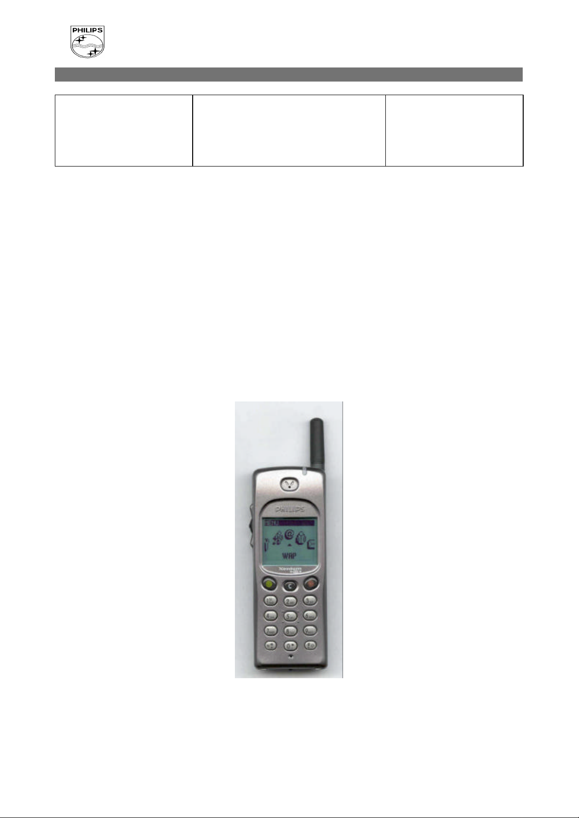
7.1 Description of the transceiver
PROCEDURE
PCC/VY/691/E/XENIUMDB998LVL1/
0038/FT/FT
Revision 3
Date : 17/12/01
Page 6 out of 30
PCC/VY/691/E/XENIUMDB998LVL1/0038/FT/FT
- 6 -
PHILIPS CONSUMER COMMUNICATIONS
PHILIPS
CUSTOMER SERVICES
SERVICE REPAIR SUPPORT
Author : Fabrice TANT
Approval : Jean Pierre HOLLANDE
Operational manager
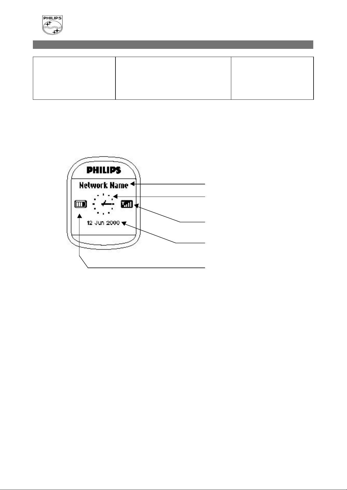
7.2 Description of the Display
PROCEDURE
PCC/VY/691/E/XENIUMDB998LVL1/
0038/FT/FT
Revision 3
Date : 17/12/01
Page 7 out of 30
Network Name : Indicates the Network on
which your phone is registered.
Clock : Indicates the hour.
Indicates the Quality of Reception. When all
4 bars appear, the reception quality is at its
best.
Indicates the Date.
Battery Level : The bars indicate the battery
level. (4 bars means full, no bars means
recharging is needed).
PCC/VY/691/E/XENIUMDB998LVL1/0038/FT/FT
- 7 -

PHILIPS CONSUMER COMMUNICATIONS
PHILIPS
CUSTOMER SERVICES
PCC/VY/691/E/XENIUMDB998LVL1/
0038/FT/FT
SERVICE REPAIR SUPPORT
Author : Fabrice TANT
Approval : Jean Pierre HOLLANDE
Operational manager
PROCEDURE
Revision 3
Date : 17/12/01
Page 8 out of 30
7.3 Using the carousel
The carousel is a circular loop of icons displayed on the screen. These icons provide access to the
different menus and sub menus used to operate your phone.
PCC/VY/691/E/XENIUMDB998LVL1/0038/FT/FT
- 8 -

PHILIPS CONSUMER COMMUNICATIONS
PHILIPS
CUSTOMER SERVICES
PCC/VY/691/E/XENIUMDB998LVL1/
0038/FT/FT
SERVICE REPAIR SUPPORT
Author : Fabrice TANT
Approval : Jean Pierre HOLLANDE
Operational manager
PROCEDURE
Revision 3
Date : 17/12/01
Page 9 out of 30
7.4 Inserting the MICRO-SIM Card
The mobile supports only the mini “plug-in” SIM card.
Push the metal retaining clip to the right and lift the cardholder. Slide in the SIM card between the
retaining clip and the plastic tongue with the cut corner of the card at the top left. Close the cardholder
and push the retaining clip to the left.
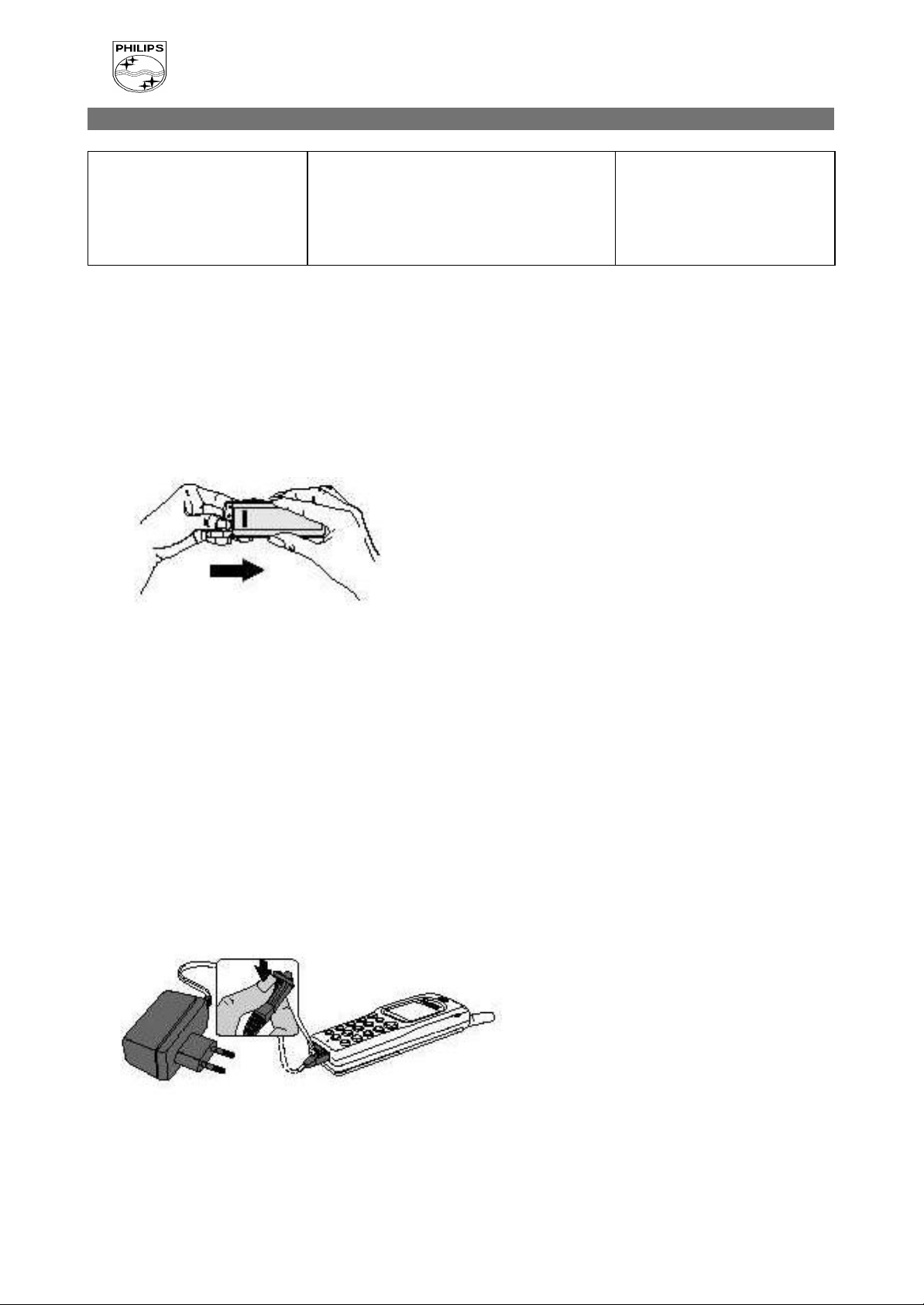
7.5 Inserting the battery
Place the battery on the back of the phone (connectors downward, the top near the arrow inside the
case).
Then push the battery into place in the direction of the antenna.
PCC/VY/691/E/XENIUMDB998LVL1/0038/FT/FT
- 9 -
PHILIPS CONSUMER COMMUNICATIONS
PHILIPS
CUSTOMER SERVICES
PCC/VY/691/E/XENIUMDB998LVL1/
0038/FT/FT
SERVICE REPAIR SUPPORT
Author : Fabrice TANT
Approval : Jean Pierre HOLLANDE
Operational manager
PROCEDURE
Revision 3
Date : 17/12/01
Page 10 out of 30
7.6 Removing the battery
Press the locking button located alongside the antenna while pushing the battery in the direction of the
arrow.
Remove battery.
7.7 Charging the battery
Plug the battery into the transceiver.
Plug the charger into the connector at the base of the transceiver.
Plug the transformer unit into the main AC power sockets.
The battery charge symbol indicates the state of the charge process :
• Bars moving - means the battery is being charged
• Steady - means the battery is fully charged
If the battery is totally discharged, the battery icon will show and start scrolling 2 to 3 minutes only
after connecting the charger.
PCC/VY/691/E/XENIUMDB998LVL1/0038/FT/FT
- 10 -
 Loading...