

Philips 74LVC1GU04GW Datasheet

INTEGRATED CIRCUITS
DATA SH EET
74LVC1GU04
Inverter
Product specification
Supersedes data of 2000 Dec 12
File under Integrated Circuits, IC24
2001 Apr 06

Philips Semiconductors Product specification
Inverter 74LVC1GU04
FEATURES
• Wide supply voltage range from 1.65 to 5.5 V
• High noise immunity
• Complies with JEDEC standard:
– JESD8-7 (1.65 to 1.95 V)
– JESD8-5 (2.3 to 2.7 V)
– JESD8B/JESD36 (2.7 to 3.6 V).
•±24 mA output drive (VCC= 3.0 V)
DESCRIPTION
The 74LVC1GU04 is a high-performance, low-power,
low-voltage, Si-gate CMOS device, superior to most
advanced CMOS compatible TTL families.
The input can be driven from either 3.3 or 5 V devices.
This feature allows the use of this device in a mixed
3.3 and 5 V environment.
The 74LVC1GU04 provides the inverting single state
unbuffered function.
• CMOS low power consumption
• Latch-up performance exceeds 250 mA
• Input accepts voltages up to 5 V
• SOT353 package.
QUICK REFERENCE DATA
Ground = 0 V; T
=25°C; tr=tf≤2.5 ns.
amb
SYMBOL PARAMETER CONDITIONS TYPICAL UNIT
t
PHL/tPLH
C
I
C
PD
propagation delay A to Y VCC= 1.8 V; CL= 30 pF; RL=1kΩ 1.7 ns
V
= 2.5 V; CL= 30 pF; RL= 500 Ω 1.3 ns
CC
V
= 3.3 V; CL= 50 pF; RL= 500 Ω 1.6 ns
CC
V
= 5.0 V; CL= 50 pF; RL= 500 Ω 1.3 ns
CC
input capacitance 6 pF
power dissipation capacitance per buffer notes 1 and 2 14.9 pF
Notes
1. C
is used to determine the dynamic power dissipation (PDin µW).
PD
PD=CPD× V
= input frequency in MHz;
f
i
2
× fi+(CL×V
CC
CC
fo= output frequency in MHz;
CL= output load capacitance in pF;
VCC= supply voltage in Volts.
2. The condition is VI= GND to VCC.
FUNCTION TABLE
See note 1.
INPUT OUTPUT
AY
LH
HL
Note
1. H = HIGH voltage level;
L = LOW voltage level.
2
× fo) where:
2001 Apr 06 2

Philips Semiconductors Product specification
Inverter 74LVC1GU04
ORDERING INFORMATION
PACKAGE
TYPE NUMBER
74LVC1GU04GW −40 to +85 °C 5 SC-88A plastic SOT353 VD
PINNING
PIN SYMBOL DESCRIPTION
1 n.c. not connected
2 A data input A
3 GND ground (0 V)
4 Y data output Y
5V
TEMPERATURE
RANGE
CC
PINS PACKAGE MATERIAL CODE MARKING
supply voltage
handbook, halfpage
handbook, halfpage
n.c.
GND
1
A
2
U04
3
5
4
MNA042
Fig.1 Pin configuration.
2
1
MNA109
V
CC
Y
handbook, halfpage
AY
2
MNA108
4
Fig.2 Logic symbol.
handbook, halfpage
4
100 Ω
A
VCCV
CC
Y
MNA636
Fig.3 IEE/IEC logic symbol.
2001 Apr 06 3
Fig.4 Logic diagram.
Philips Semiconductors Product specification
Inverter 74LVC1GU04
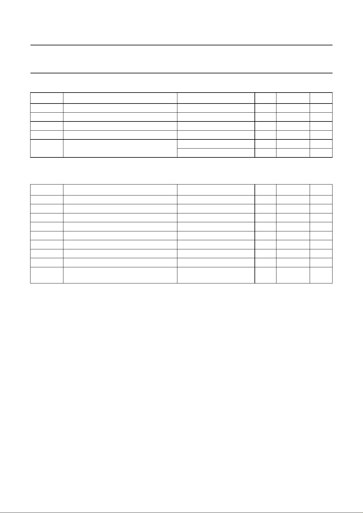
RECOMMENDED OPERATING CONDITIONS
SYMBOL PARAMETER CONDITIONS MIN. MAX. UNIT
V
CC
V
I
V
O
T
amb
t
, t
r
f
LIMITING VALUES
In accordance with theAbsolute Maximum Rating System (IEC 60134); voltages are referenced to GND (ground = 0 V).
SYMBOL PARAMETER CONDITIONS MIN. MAX. UNIT
V
CC
I
IK
V
I
I
OK
V
O
I
O
, I
I
CC
GND
T
stg
P
D
supply voltage 1.65 5.5 V
input voltage 0 5.5 V
output voltage 0 V
CC
V
operating ambient temperature −40 +85 °C
input rise and fall times VCC= 1.65 to 2.7 V 0 20 ns/V
V
= 2.7 to 5.5 V 0 10 ns/V
CC
supply voltage −0.5 +6.5 V
input diode current VI<0 −−50 mA
input voltage note 1 −0.5 +6.5 V
output diode current VO>VCC or VO<0 −±50 mA
output voltage note 1 −0.5 VCC+ 0.5 V
output source or sink current VO=0toV
CC
−±50 mA
VCC or GND current −±100 mA
storage temperature −65 +150 °C
power dissipation per package for temperature range from
− 200 mW
−40 to +85 °C; note 2
Notes
1. The input and output voltage ratings may be exceeded if the input and output current ratings are observed.
2. Above 55 °C the value of PD derates linearly with 2.5 mW/K.
2001 Apr 06 4

Philips Semiconductors Product specification
Inverter 74LVC1GU04
DC CHARACTERISTICS
At recommended operating conditions; voltage are referenced to GND (ground=0V).
SYMBOL PARAMETER
V
IH
HIGH-level input
voltage
V
IL
LOW-level input
voltage
V
OL
LOW-level
output voltage
V
OH
HIGH-level
output voltage
I
LI
input leakage
current
I
CC
quiescentsupply
current
TEST CONDITIONS T
OTHER VCC (V)
MIN. TYP.
(°C)
amb
−40 to +85
(1)
UNIT
MAX.
1.65 to 5.5 0.75 × VCC−− V
1.65 to 5.5 −−0.25 × V
CC
V
VI=VIHor VIL; IO= 100 µA 1.65 to 5.5 −−0.1 V
V
V
V
V
V
or VIL; IO= 4 mA 1.65 −−0.45 V
I=VIH
or VIL; IO= 8 mA 2.3 −−0.3 V
I=VIH
or VIL; IO= 12 mA 2.7 −−0.4 V
I=VIH
or VIL; IO= 24 mA 3.0 −−0.55 V
I=VIH
or VIL; IO= 32 mA 4.5 −−0.55 V
I=VIH
VI=VIHor VIL; IO= −100 µA 1.65 to 5.5 VCC− 0.1 −− V
V
V
V
V
V
or VIL; IO= −4 mA 1.65 1.2 −− V
I=VIH
or VIL; IO= −8 mA 2.3 1.9 −− V
I=VIH
or VIL; IO= −12 mA 2.7 2.2 −− V
I=VIH
or VIL; IO= −24 mA 3.0 2.3 −− V
I=VIH
or VIL; IO= −32 mA 4.5 3.8 −− V
I=VIH
VI= 5.5 Vor GND 3.6 −±0.1 ±5 µA
VI=VCCor GND; IO= 0 5.5 − 0.1 10 µA
Note
1. All typical values are measured at V
= 3.3 V and T
CC
amb
2001 Apr 06 5
=25°C.
 Loading...