

Philips 74hc hct85 DATASHEETS
INTEGRATED CIRCUITS
DATA SH EET
For a complete data sheet, please also download:
•The IC06 74HC/HCT/HCU/HCMOS Logic Family Specifications
•The IC06 74HC/HCT/HCU/HCMOS Logic Package Information
•The IC06 74HC/HCT/HCU/HCMOS Logic Package Outlines
74HC/HCT85
4-bit magnitude comparator
Product specification
File under Integrated Circuits, IC06
December 1990
Philips Semiconductors Product specification
4-bit magnitude comparator 74HC/HCT85
FEATURES
• Serial or parallel expansion without extra gating
• Magnitude comparison of any binary words
• Output capability: standard
• ICC category: MSI
weighted (A0 to A3 and B0 to B3), where A3 and B3 are the
most significant bits.
The operation of the “85” is described in the function table,
showing all possible logic conditions. The upper part of the
table describes the normal operation under all conditions
that will occur in a single device or in a series expansion
scheme. In the upper part of the table the three outputs are
GENERAL DESCRIPTION
The 74HC/HCT85 are high-speed Si-gate CMOS devices
and are pin compatible with low power Schottky TTL
(LSTTL). They are specified in compliance with JEDEC
standard no. 7A.
The 74HC/HCT85 are 4-bit magnitude comparators that
can be expanded to almost any length. They perform
comparison of two 4-bit binary, BCD or other monotonic
codes and present the three possible magnitude results at
, Q
the outputs (Q
A>B
A=B
and Q
). The 4-bit inputs are
A<B
mutually exclusive. In the lower part of the table, the
outputs reflect the feed forward conditions that exist in the
parallel expansion scheme.
For proper compare operation the expander inputs (I
I
A=B
and I
) to the least significant position must be
A<B
connected as follows: I
I
= HIGH.
A=B
For words greater than 4-bits, units can be cascaded by
connecting outputs Q
corresponding inputs of the significant comparator.
QUICK REFERENCE DATA
GND = 0 V; T
=25°C; tr=tf= 6 ns
amb
SYMBOL PARAMETER CONDITIONS
t
PHL/ tPLH
C
I
C
PD
propagation delay CL= 15 pF; VCC=5 V
A
, Bn to Q
n
, Bn to Q
A
n
I
A<B,
I
to Q
A=B
, I
A=B
, I
A=B
A>B
A=B
A>B
, Q
to Q
A<B
A<B
, Q
A>B
input capacitance 3.5 3.5 pF
power dissipation capacitance per package notes 1 and 2 18 20 pF
A<B=IA>B
, Q
A<B
A>Β
= = LOW and
and Q
A=B
to the
TYPICAL
HC HCT
20 22 ns
18 20 ns
15 15 ns
11 15 ns
A>B
UNIT
,
Notes
1. C
is used to determine the dynamic power dissipation (PD in µW):
PD
PD=CPD× V
2
× fi+ ∑ (CL× V
CC
2
× fo) where:
CC
fi= input frequency in MHz
fo= output frequency in MHz
∑ (CL× V
2
× fo) = sum of outputs
CC
CL= output load capacitance in pF
VCC= supply voltage in V
2. For HC the condition is VI= GND to V
CC
For HCT the condition is VI= GND to VCC− 1.5 V
ORDERING INFORMATION
“74HC/HCT/HCU/HCMOS Logic Package Information”
See
December 1990 2
.
Philips Semiconductors Product specification
4-bit magnitude comparator 74HC/HCT85
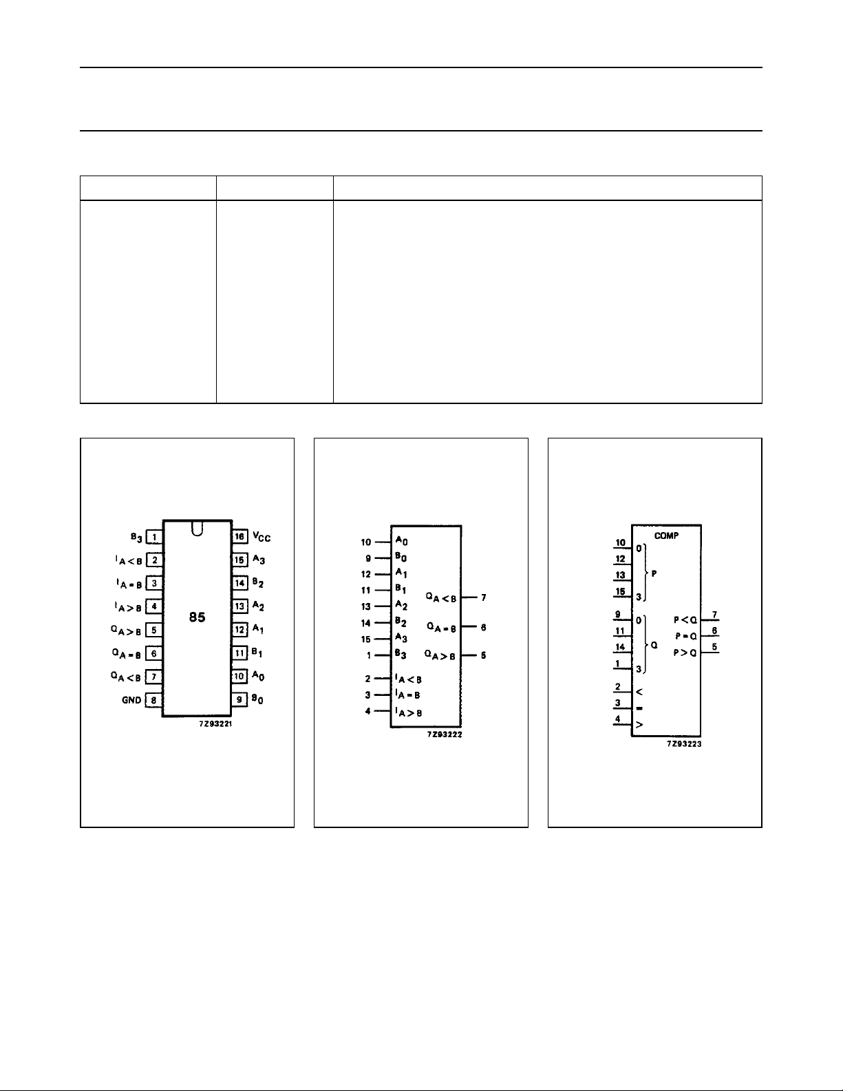
PIN DESCRIPTION
PIN NO. SYMBOL NAME AND FUNCTION
2I
3I
4I
5Q
6Q
7Q
A<B
A=B
A>B
A>B
A=B
A<B
8 GND ground (0 V)
9, 11, 14, 1, B
10, 12, 13, 15 A
16 V
to B
0
to A
0
CC
3
3
A< B expansion input
A = B expansion input
A>B expansion input
A> B output
A = B output
A<B output
word B inputs
word A inputs
positive supply voltage
Fig.1 Pin configuration. Fig.2 Logic symbol. Fig.3 IEC logic symbol.
December 1990 3
 Loading...