

Philips 74hc hct238 DATASHEETS

INTEGRATED CIRCUITS
DATA SH EET
For a complete data sheet, please also download:
•The IC06 74HC/HCT/HCU/HCMOS Logic Family Specifications
•The IC06 74HC/HCT/HCU/HCMOS Logic Package Information
•The IC06 74HC/HCT/HCU/HCMOS Logic Package Outlines
74HC/HCT238
3-to-8 line decoder/demultiplexer
Product specification
File under Integrated Circuits, IC06
December 1990
Philips Semiconductors Product specification
3-to-8 line decoder/demultiplexer 74HC/HCT238
FEATURES
• Demultiplexing capability
• Multiple input enable for easy expansion
• Ideal for memory chip select decoding
• Active HIGH mutually exclusive outputs
• Output capability: standard
• ICC category: MSI
provide 8 mutually exclusive active HIGH outputs
(Y0 to Y7).
The “238” features three enable inputs: two active LOW
(E1 and E2) and one active HIGH (E3). Every output will be
LOW unless E1 and E2 are LOW and E3 is HIGH.
This multiple enable function allows easy parallel
expansion of the “238” to a 1-of-32 (5 lines to 32 lines)
decoder with just four “238” ICs and one inverter.
The “238” can be used as an eight output demultiplexer by
GENERAL DESCRIPTION
The 74HC/HCT238 are high-speed Si-gate CMOS devices
and are pin compatible with low power Schottky TTL
(LSTTL). They are specified in compliance with JEDEC
standard no. 7A.
using one of the active LOW enable inputs as the data
input and the remaining enable inputs as strobes. Unused
enable inputs must be permanently tied to their
appropriate active HIGH or LOW state.
The “238” is identical to the “138” but has non-inverting
outputs.
The 74HC/HCT238 decoders accept three binary
weighted address inputs (A
, A1, A2) and when enabled,
0
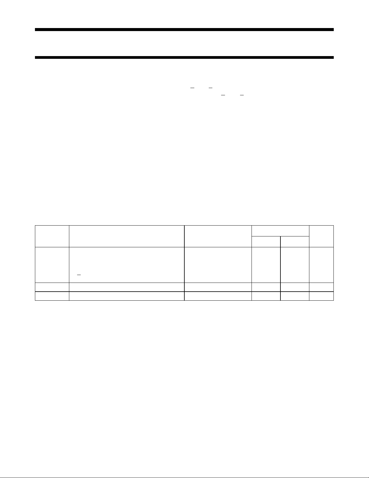
QUICK REFERENCE DATA
GND = 0 V; T
=25°C; tr=tf= 6 ns
amb
SYMBOL PARAMETER CONDITIONS
t
PHL/ tPLH
C
I
C
PD
propagation delay CL= 15 pF; VCC=5 V
A
to Y
n
n
E
to Y
3
n
En to Y
n
input capacitance 3.5 3.5 pF
power dissipation capacitance per package notes 1 and 2 72 76 pF
TYPICAL
UNIT
HC HCT
14 18 ns
16 20 ns
17 21 ns
Notes
1. C
is used to determine the dynamic power dissipation (PD in µW):
PD
PD=CPD× V
2
× fi+ ∑ (CL× V
CC
2
× fo) where:
CC
fi= input frequency in MHz
fo= output frequency in MHz
∑ (CL× V
2
× fo) = sum of outputs
CC
CL= output load capacitance in pF
VCC= supply voltage in V
2. For HC the condition is VI= GND to V
CC
For HCT the condition is VI= GND to VCC− 1.5 V
ORDERING INFORMATION
“74HC/HCT/HCU/HCMOS Logic Package Information”
See
December 1990 2
.
Philips Semiconductors Product specification
3-to-8 line decoder/demultiplexer 74HC/HCT238
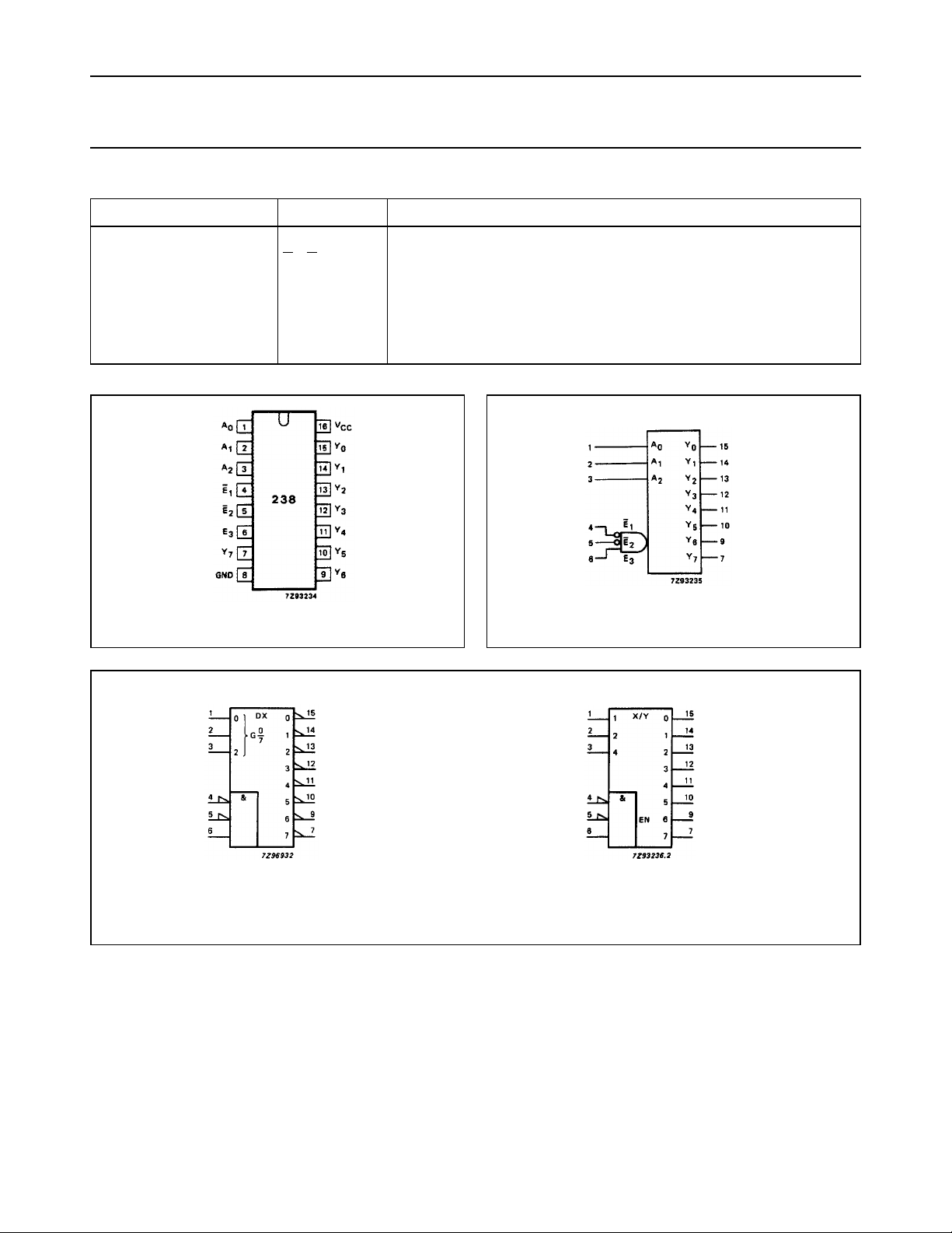
PIN DESCRIPTION
PIN NO. SYMBOL NAME AND FUNCTION
1, 2, 3 A
4, 5
6E
8 GND ground (0 V)
15, 14, 13, 12, 11, 10, 9, 7 Y
16 V
to A
0
2
E1, E
2
3
to Y
0
7
CC
address inputs
enable inputs (active LOW)
enable input (active HIGH)
outputs (active HIGH)
positive supply voltage
Fig.1 Pin configuration. Fig.2 Logic symbol.
(a)
(b)
Fig.3 IEC logic symbol.
December 1990 3
 Loading...