

Philips 74hc hct182 DATASHEETS

INTEGRATED CIRCUITS
DATA SH EET
For a complete data sheet, please also download:
•The IC06 74HC/HCT/HCU/HCMOS Logic Family Specifications
•The IC06 74HC/HCT/HCU/HCMOS Logic Package Information
•The IC06 74HC/HCT/HCU/HCMOS Logic Package Outlines
74HC/HCT182
Look-ahead carry generator
Product specification
File under Integrated Circuits, IC06
December 1990

Philips Semiconductors Product specification
Look-ahead carry generator 74HC/HCT182
FEATURES
• Provides carry look-ahead across a group of four ALU’s
• Multi-level look-ahead for high-speed arithmetic
operation over long word length
• Output capability: standard
• ICC category: MSI
GENERAL DESCRIPTION
The 74HC/HCT182 are high-speed Si-gate CMOS devices
and are pin compatible with low power Schottky TTL
(LSTTL). They are specified in compliance with JEDEC
anticipated active HIGH carries (C
four groups of binary adders.
The “182” also has active LOW carry propagate (P) and
carry generate (G) outputs which may be used for further
levels of look-ahead.
The logic equations provided at the outputs are:
C
n+x=G0+P0Cn
C
n+y=G1+P1G0+P1P0Cn
C
n+z=G2+P2G1+P2P1G0+P2P1P0Cn
GG
PP
=
standard no. 7A.
The 74HC/HCT182 carry look-ahead generators accept
up to four pairs of active LOW carry propagate (
P0, P1, P2,
P3) and carry generate (G0, G1, G2, G3) signals and an
active HIGH carry input (Cn). The devices provide
The “182” can also be used with binary ALU’s in an active
LOW or active HIGH input operand mode. The
connections to and from the ALU to the carry look-ahead
generator are identical in both cases.
QUICK REFERENCE DATA
GND = 0 V; T
=25°C; tr=tf= 6 ns
amb
SYMBOL PARAMETER CONDITIONS
t
PHL
/ t
PLH
propagation delay
CL= 15 pF; VCC=5 V
Pn to P
Cn to any output
Pn or Gn to any output
C
I
C
PD
input capacitance 3.5 3.5 pF
power dissipation capacitance per
notes 1 and 2
package
P3G2P3P2G1P3P2P1G
++ +=
3
P2P1P
3
0
TYPICAL
HC HCT
11
17
14
50 50 pF
n+x
, C
14
21
17
n+y
O
, C
) across
n+z
ns
ns
ns
UNIT
Notes
1. C
is used to determine the dynamic power dissipation (PD in µW):
PD
PD=CPD× V
2
× fi+∑(CL× V
CC
2
× fo) where:
CC
fi= input frequency in MHz
fo= output frequency in MHz
∑ (CL× V
2
× fo) = sum of outputs
CC
CL= output load capacitance in pF
VCC= supply voltage in V
2. For HC the condition is VI= GND to V
CC
For HCT the condition is VI= GND to VCC− 1.5 V
ORDERING INFORMATION
“74HC/HCT/HCU/HCMOS Logic Package Information”
See
December 1990 2
.
Philips Semiconductors Product specification
Look-ahead carry generator 74HC/HCT182
PIN DESCRIPTION
PIN NO. SYMBOL NAME AND FUNCTION
3, 1, 14, 5
4, 2, 15, 6
7
8 GND ground (0 V)
9C
10
11 C
12 C
13 C
16 V
G0 to G
P0 to P
3
3
carry generate inputs (active LOW)
carry propagate inputs (active LOW)
P carry propagate output (active LOW)
n+z
function output
G carry generate output (active LOW)
n+y
n+x
n
CC
function output
function output
carry input (active HIGH)
positive supply voltage
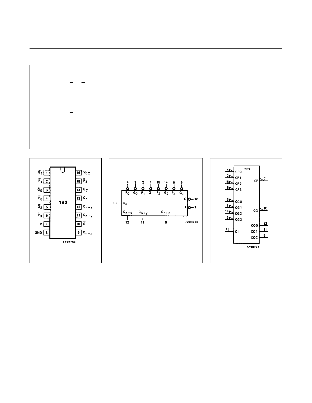
Fig.1 Pin configuration. Fig.2 Logic symbol.
December 1990 3
Fig.3 IEC logic symbol.
 Loading...