

Philips 74HC7014N, 74HC7014D Datasheet
INTEGRATED CIRCUITS
DATA SH EET
For a complete data sheet, please also download:
•The IC06 74HC/HCT/HCU/HCMOS Logic Family Specifications
•The IC06 74HC/HCT/HCU/HCMOS Logic Package Information
•The IC06 74HC/HCT/HCU/HCMOS Logic Package Outlines
74HC7014
Hex non-inverting precision
Schmitt-trigger
Product specification
Supersedes data of September 1993
File under Integrated Circuits, IC06
1998 Jul 08
Philips Semiconductors Product specification
Hex non-inverting precision Schmitt-trigger 74HC7014
FEATURES
• Operating voltage 3 to 6 V
• Output capability: standard
• category: SSI
APPLICATIONS
• Wave and pulse shapers for highly
noisy environments
DESCRIPTION
The 74HC7014 is a high-speed
Si-gate CMOS device. It is specified
in compliance with JEDEC standard
no. 7A.
The 74HC7014 provides six precision
Schmitt-triggers with non-inverting
buffers. It is capable of transforming
slowly changing input signals into
sharply defined, jitter-free output
signals. The precisely defined trigger
levels are lying in a window between
0.55 × V
and 0.65 × VCC. This
CC
makes the circuit suitable to operate
in a highly noisy environment. Input
shorts are allowed to −1.5 V and 16 V
without disturbing other channels.
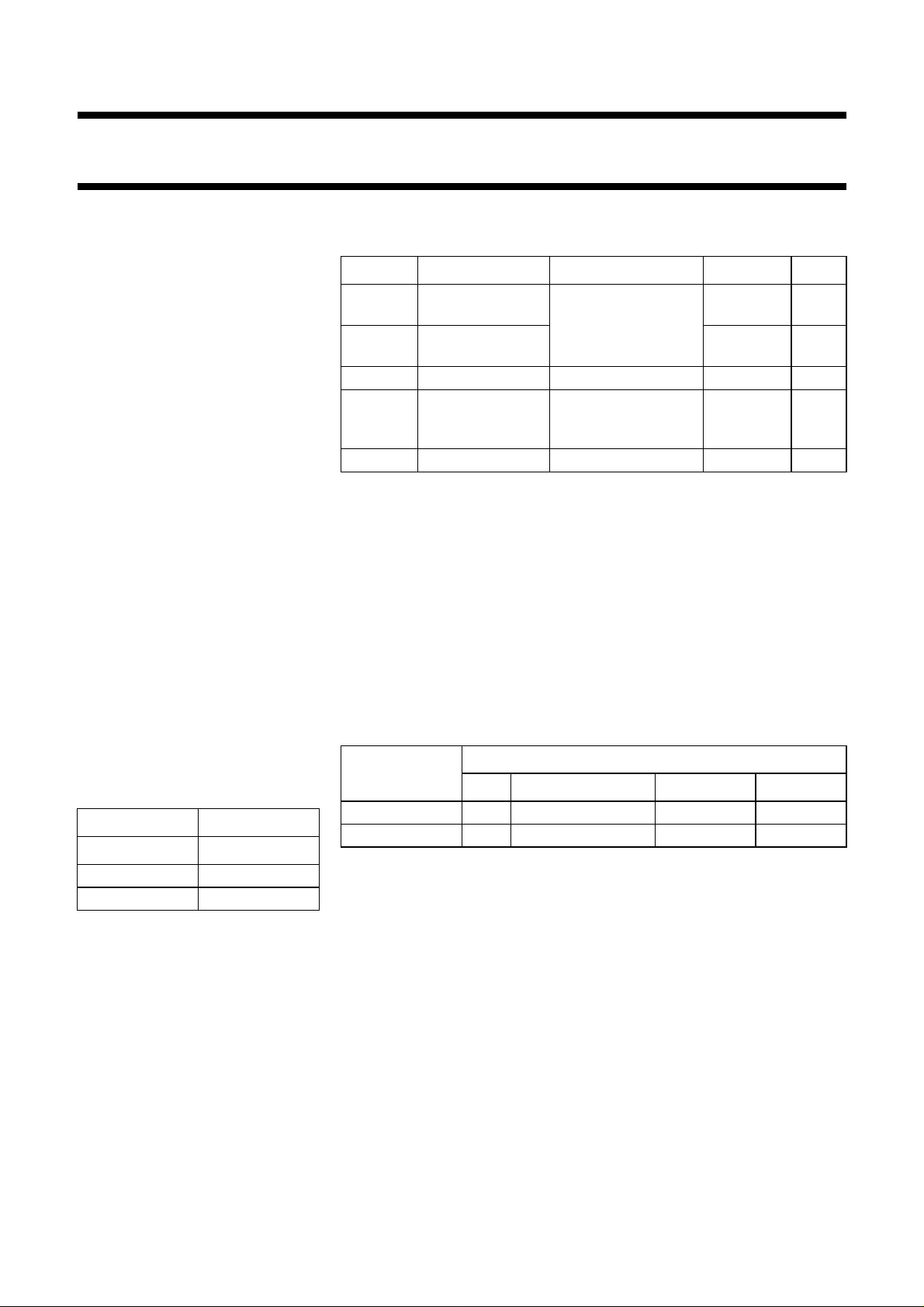
FUNCTION TABLE
INPUT OUTPUT
nA nY
LL
HH
QUICK REFERENCE DATA
GND = 0 V; T
= 25 °C; tr= tf= 6 ns
amb
SYMBOL PARAMETER CONDITIONS TYPICAL UNIT
V
T+
positive going
CL= 50 pF; VCC= 5 V 3.1 V
threshold
V
T−
negative going
2.9 V
threshold
C
I
C
PD
input capacitance 3.5 pF
power dissipation
notes 1 and 2 9 pF
capacitance per
gate
I
CC
DC supply current 3.0 mA
Notes to the quick reference data
1. C
is used to determine the dynamic power dissipation (PDin µW):
PD
PD= CPD× V
2
× fi+ ∑ (CL× V
CC
2
× fo) where:
CC
fi= input frequency in MHz.
fo= output frequency in MHz.
CL= output load capacitance in pF.
VCC= supply voltage in V.
∑ (CL× V
2. For HC the condition is VI= GND to V
2
× fo) = sum of outputs.
CC
CC.
ORDERING INFORMATION
PACKAGE
TYPE NUMBER
PINS PIN POSITION MATERIAL CODE
74HC7014N 14 DIP plastic SOT27-1
74HC7014D 14 SO plastic SOT108-1
Note
1. H = HIGH voltage level
L = LOW voltage level
1998 Jul 08 2
Philips Semiconductors Product specification
Hex non-inverting precision Schmitt-trigger 74HC7014
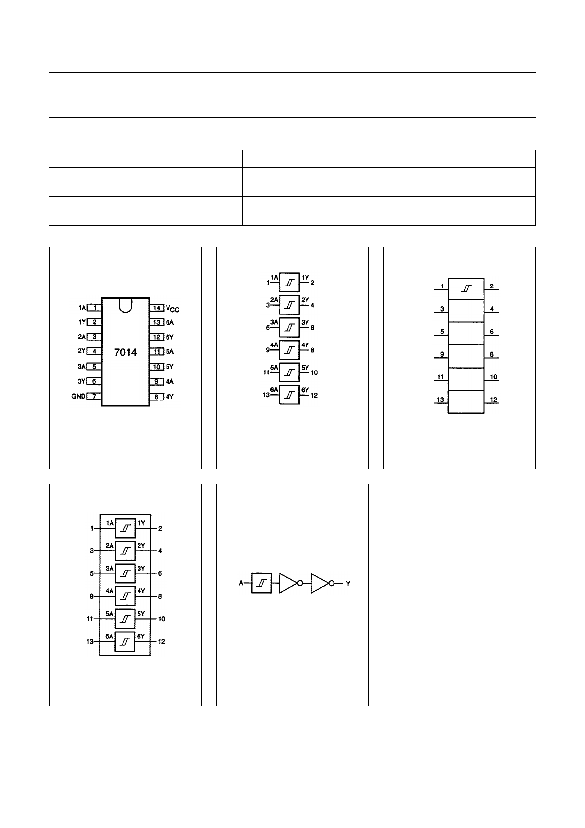
PINNING
PIN NO. SYMBOL NAME AND FUNCTION
1, 3, 5, 9, 11, 13 1A to 6A data inputs
2, 4, 6, 8, 10, 12 1Y to 6Y data outputs
7 GND ground (0 V)
14 V
CC
positive supply voltage
Fig.1 Pin configuration. Fig.2 Logic symbol. Fig.3 IEC logic symbol.
Fig.4 Functional diagram.
Fig.5 Logic diagram
(one Schmitt-trigger).
1998 Jul 08 3
 Loading...