

Philips 74f381 DATASHEETS

Philips Semiconductors Product specification
74F381Arithmetic Logic Unit
1
1989 Mar 01 853–0418 95907
FEATURES
•Low-input loading minimizes drive requirements
•Performs six arithmetic and logic functions
•Selectable Low (clear) and High (preset) functions
•Carry Generate and Propagate outputs for use with Carry
look-ahead generator
DESCRIPTION
The 74F381 performs three arithmetic and three logic operations on
two 4-bit words, A and B. Three additional Select (S0–S2) input
codes force the Function outputs Low or High. Carry Propagate (P
)
and Generate (G
) ouputs are provided for use with the 74F182
Carry Look Ahead Generator for high-speed expansion to longer
word lengths. For ripple expansion, refer to the 74F382 ALU data
sheet.
Signals applied to the Select inputs (S0–S2) determine the mode of
operation, as indicated in the Function Select Table. An extensive
listing of input and output function levels is shown in the Function
Table. The circuit performs the arithmetic functions for either
active-HIgh or active-Low operands, with output levels in the same
convention. In the subtract operating modes, it is necessary to force
a Carry (High for active-HIgh operands, Low for active-Low
operands) into the Cn input of the least significant package. The
Carry Generate (G
) and Carry Propagate (P) outputs supply input
signals to the 74F182 Carry look-ahead generator for expansion to
longer word length, as shown in Figure 1. Note that a 74F382 ALU is
used for the most significant package. Typical delays for Figure 1
are given in Table 1.
PIN CONFIGURATION
20
19
18
17
16
15
147
6
5
4
3
2
1
138
V
CC
A1
B1
A0
B0
S0
S1
S2
F0
F1
GND
A2
B2
A3
B3
Cn
P
G
F3
F2
SF00921
129
1110
TYPICAL
PROPAGATION
DELAY
TYPICAL SUPPL Y
CURRENT (TOTAL)
74F381 6.5ns 59mA
ORDERING INFORMATION
DESCRIPTION
COMMERCIAL RANGE
V
CC
= 5V ±10%, T
amb
= 0°C to +70°C
20-pin plastic DIP N74F381N
20-pin plastic SO N74F381D
INPUT AND OUTPUT LOADING AND FAN OUT TABLE
PINS DESCRIPTION
74F (U.L.)
HIGH/LOW
LOAD VALUE
HIGH/LOW
A0 – A3 A operand inputs 1.0/4.0 20µA/2.4mA
B0 – B3 A operand inputs 1.0/4.0 20µA/2.4mA
S0 – S2 Function select inputs 1.0/1.0 20µA/0.6mA
Cn Carry input 1.0/4.0 20µA/2.4mA
P Carry Propagate ouptut (active-Low) 50/33 1.0mA/20mA
G Carry Generate ouptut (active-Low) 50/33 1.0mA/20mA
F0–F3 Outputs 50/33 1.0mA/20mA
NOTE:
One (1.0) FAST unit load is defined as 20µA in the High state and 0.6mA in the Low state.
TYPE
Philips Semiconductors Product specification
74F381Arithmetic Logic Unit
1989 Mar 01
2
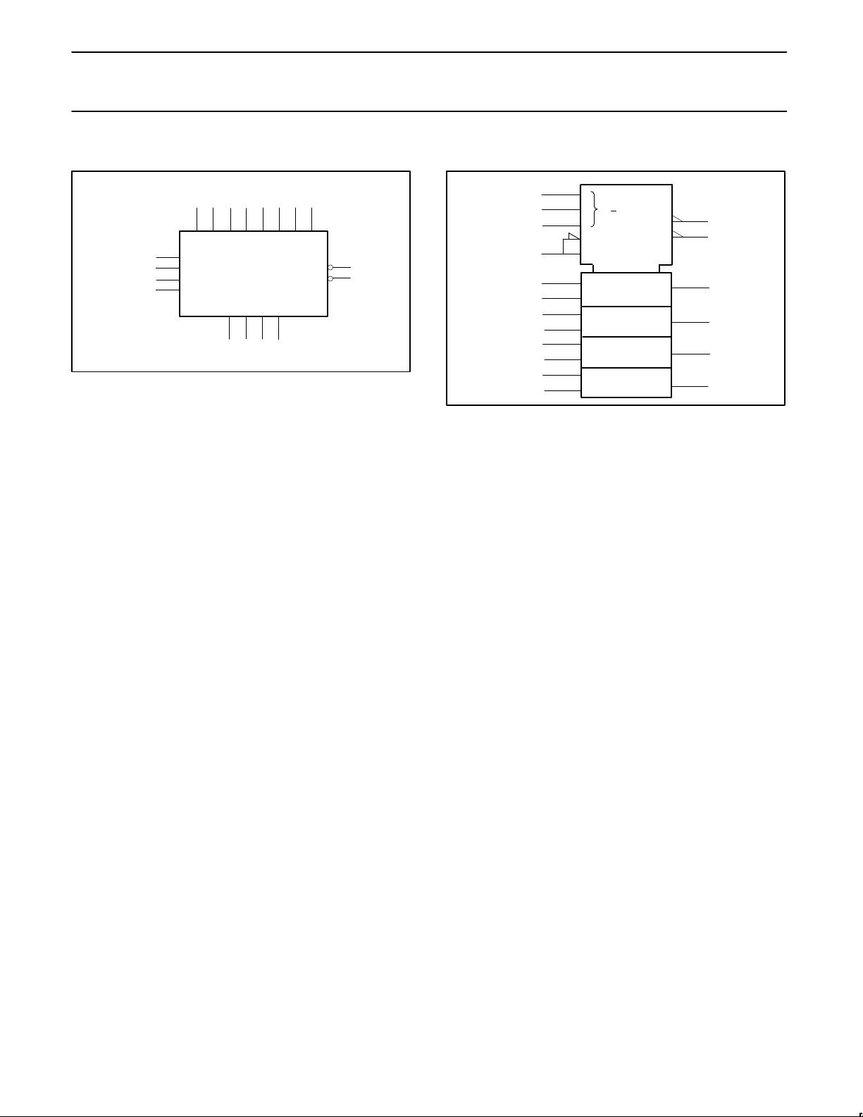
LOGIC SYMBOL
F0 F1 F2 F3
V
CC
= Pin 20
GND = Pin 10
A0 B0 A1 B1 A2 B2 A3 B3
3 4 1 2 19 18 17 16
Cn
S0
S1
S2
15
5
6
7
8 9 11 12
SF00922
G
P
13
14
IEC/IEEE SYMBOL
8
9
11
12
(1/2) Bl
15
P
SF00923
3
4
1
2
19
18
17
16
Q
P
Q
P
Q
P
Q
[1]
[2]
[4]
[8]
0
4
3 Cl
(1/2/3) CP
(1/2/3) CG
M
0
7
5
6
7
14
13
ALU
Philips Semiconductors Product specification
74F381Arithmetic Logic Unit
1989 Mar 01
3
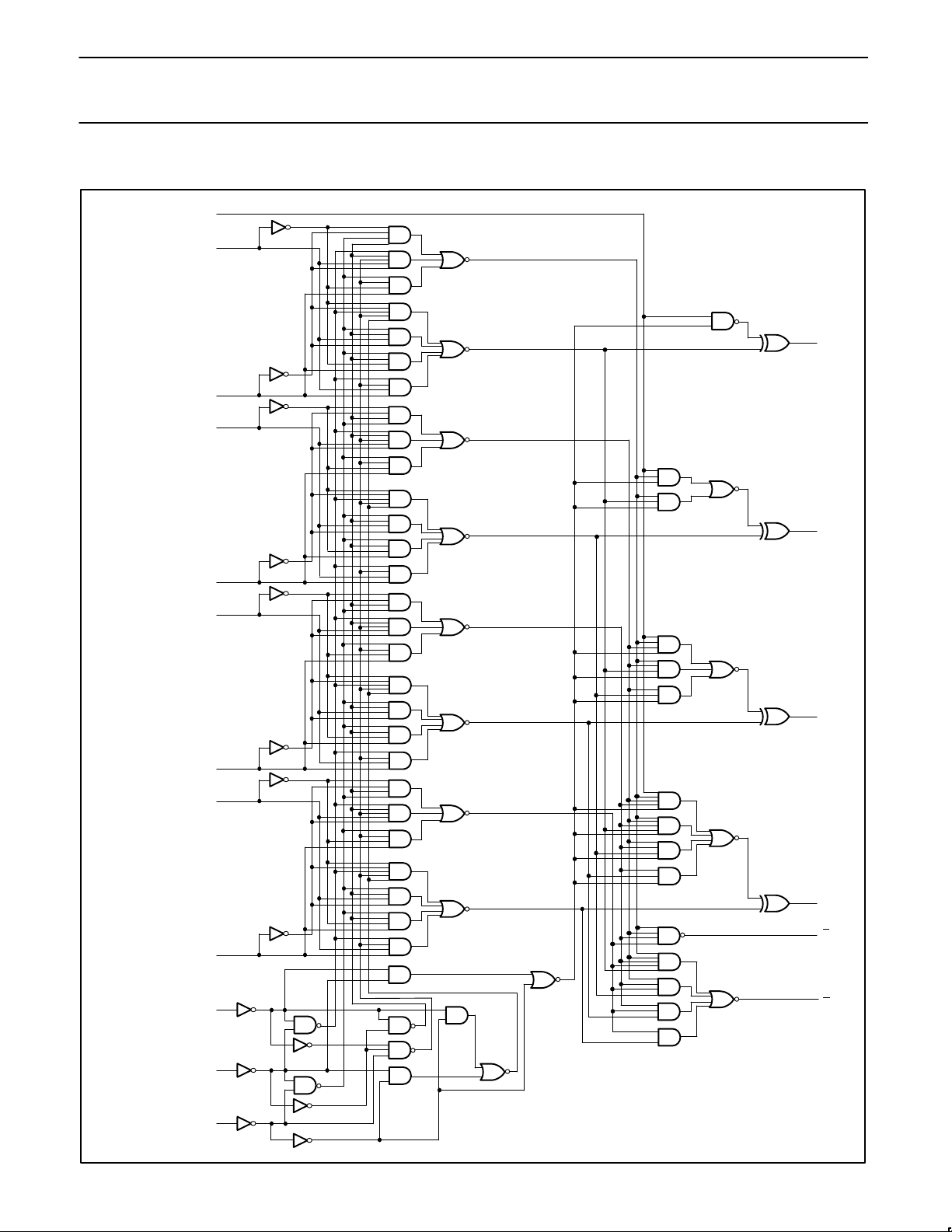
LOGIC DIAGRAM
VCC = Pin 20
GND = Pin 10
3
4
1
2
19
18
17
16
5
6
7
15
Cn
A0
B0
A1
B1
A2
B2
A3
B3
S0
S1
S2
8
9
11
12
14
13
F0
F1
F2
F3
P
G
SF00924
 Loading...