

Page 1
Philips Lighting North America Corporation
200 Franklin Square Drive
Somerset, NJ 08873, USA
Phone: 855-486-2216
www.philips.com/luminaires
Philips Lighting Canada Ltd.
281 Hillmount Road,
Markham ON, Canada L6C 2S3
Phone: 800-668-9008
www.philips.com/luminaires
9140053562 February 2016
WARNING – Shut off AC power to branch
circuits to which units will be connected. All
wiring should be per N.E.C. Articles 501-4(b)
and local codes.
To maintain warranty, equipment with batteries
must be installed or placed on charge within
prescribed period after shipment.
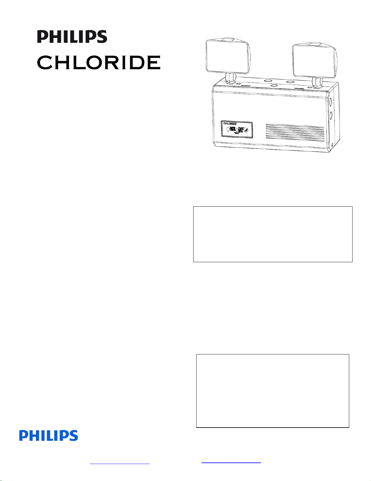
6MIC/2MIC Series
25W-50W Emergency
120V/230V/240V Luminaire
Service Questions Call: 910-259-1000
INSTALLATION AND
OPERATING
INSTRUCTIONS
IMPORTANT SAFEGUARDS
When using electrical equipment, basic safety
precautions should always be followed, including
the following:
READ AND FOLLOW ALL
SAFETY INSTRUCTIONS
All servicing should be performed by qualified
personnel only.
Equipment should be mounted in locations and at
heights where it will not be readily subjected to
tampering by unauthorized personnel.
The use of accessory equipment not recommended
by the manufacturer may cause an unsafe condition.
Do not use this equipment for other than intended
use.
Do not use outdoors.
Do not let supply cords touch hot surfaces.
Do not mount near gas or electric heaters.
CAUTION: Halogen cycle lamp(s) are used in
this equipment. To avoid shattering: Do not
operate lamp in excess of rated voltage, protect
lamp against abrasion and scratches and against
liquids when lamp is operating, dispose of lamp
with care.
Halogen cycle lamps operate at high temperatures.
Do not store or place flammable materials near
lamp.
CAUTION: “To avoid electrical overload, total
connected lamp load (factory and field installed)
should not exceed output rating”.
SAVE THESE
Page 2

Philips Lighting North America Corporation
200 Franklin Square Drive
Somerset, NJ 08873, USA
Phone: 855-486-2216
www.philips.com/luminaires
Philips Lighting Canada Ltd.
281 Hillmount Road,
Markham ON, Canada L6C 2S3
Phone: 800-668-9008
www.philips.com/luminaires
9140053579 February 2016
INSTRUCTIONS
GENERAL INSTRUCTIONS
1) Begin the installation process by
determining mounting options.
2) The slotted, circular keyways can be used to
secure the housing to a standard junction
box. The junction box must be secured
sufficiently to handle the weight of the unit.
3) Additionally, two slotted vertical keyway
slots (Figure 1) may be used to attach the
housing to independent anchor supports.
Use three #8 toggle bolts (supplied by
others) for securing to wallboard or hollow
concrete walls. If the wiring is wall
recessed, run wires through center hole of
housing in preparation for unit wiring.
Figure 1
HOOKUP INSTRUCTIONS
Standard Units:
Connect A.C. service to unit charger leads:
Brown = 240 VAC
Violet = 230 VAC
Black = 120 VAC
Light Blue = Common
Green = Ground
1. Connect remote lamps, if applicable.
Connect orange lead to RL+ and yellow lead
to RL-. Ensure total unit load (including
internal lamps) does not exceed unit rating
2. Install battery(ies). Refer to next section and
illustrations.
3. Adjust head(s) to illuminate desired area(s).
4. Close cover. Ensure electrical wires and
membrane switch cable remains inside unit
and do not interfere with cover closure.
INSTALLING BATTERIES
1. Units may ship without batteries installed
depending on the wattage of the unit. For
lead units, battery wiring harnesses are
already connected to PCB assembly and
connection to the batteries is required. In
the case of Nicad units, connection of
battery harness to the PCB is required.
2. Install and wire batteries as appropriate.
(See Page 6 for battery configurations)
3. Tighten straps to secure batteries inside unit.
OPERATING INSTRUCTIONS
1. Normal Power-Up Sequence
At power-up, the red and green LED
indicators will alternately flash for one to
two seconds. Next, the unit will go through
a “Power-up Quick Test” with the green
LED flashing quickly. If no power-up faults
are detected, the green LED will then flash
slowly for approximately 36-72 hours to
indicate the unit is in a high rate of charge.
If any faults are detected during ‘Power-up
Quick Test’, these will be indicated by a
flashing red LED indicator (Reference Table
2). The red LED may be accompanied by a
buzzer. In the event of a unit error, this
buzzer may be disabled by a short press of
the test switch and will remain disabled for a
period of 196 hours (8 days). After the fault
has been corrected, the red LED flash and
buzzer will be cleared automatically and the
unit will return to normal operation.
Page 3

Philips Lighting North America Corporation
200 Franklin Square Drive
Somerset, NJ 08873, USA
Phone: 855-486-2216
www.philips.com/luminaires
Philips Lighting Canada Ltd.
281 Hillmount Road,
Markham ON, Canada L6C 2S3
Phone: 800-668-9008
www.philips.com/luminaires
9140053579 February 2016
2. Press and hold the ‘TEST’ button. The
lamps should illuminate and the green
indicator lamp indicate steady green while
the lamps are on.
3. Release ‘TEST’ button. Lamps should
extinguish and the green indicator lamp
should be steady green if batteries are in
maintenance charge or blinking indicating a
high rate of charge.
4. Leave A.C. connected for a minimum of 24
hours before performing any abbreviated
testing. Full recharge of batteries may take
up to 72 hours.
5. Once energized, the unit will wait 36 hours
while the batteries are charged and then
perform an automatic lamp load calculation.
The system will then detect and indicate a
load loss of 10% and indicate a lamp failure.
Replace lamps as required. Upon lamp
replacement, run any manual self-test and
the system will return to normal operating
status.
6. If, after installation and calibration, lamp
load is increased or decreased the system
will need to be manually calibrated for the
new total load. To re-calibrate, press the test
switch four times. The unit will illuminate
for 30 seconds and then return to normal
operation status.
7. Lamp re-calibration can also be
accomplished with the optional remote
control by pressing in sequence, ‘Silence,
Silence, Cancel, Silence’. The lamps will
illuminate for a brief time and then return to
normal operation status.
SELF-TEST / SELF-DIAGNOSTICS
1. This unit’s charge / discharge circuit is
microprocessor controlled. The charging
circuit consists of a two stage charging
program which will charge the batteries at a
high rate of charge and once the batteries
approach the correct float voltage, the
charger will switch to a maintenance charge
mode.
2. The microprocessor controls and detects the
following conditions:
a. Low Voltage Disconnect (LVD) –
Disconnects battery power from unit
when battery voltage drops below
87.5% of nominal voltage to protect
the batteries from deep discharge.
b. AC Brownout – Disconnects the unit
from line voltage and transfers the
unit to emergency mode when the
line voltage sags to 80% or below.
c. AC Lock OUT – When line voltage
and battery voltage is removed from
the unit, the unit will remain off until
line voltage is returned. Used to
place the unit into hibernation.
d. Temperature Compensation –
Battery voltage temperature
compensation is performed by the
microprocessor on a continual basis
based on unit ambient temperature
conditions.
e. Lamp Load Failure Detect –
Indicated a load failure when more
than 10% of the original load is
determined to be removed.
f. Reverse battery connection polarity.
3. For information regarding failure mode
indications, see Failure Codes Table 2
below.
Page 4

Philips Lighting North America Corporation
200 Franklin Square Drive
Somerset, NJ 08873, USA
Phone: 855-486-2216
www.philips.com/luminaires
Philips Lighting Canada Ltd.
281 Hillmount Road,
Markham ON, Canada L6C 2S3
Phone: 800-668-9008
www.philips.com/luminaires
9140053579 February 2016
Manual Test Procedure
Test Switch
Presses
Test Performed
Press and Hold
Switches the unit to
emergency mode and
remains in that mode
until the user releases
the Test Switch.
Single Press
Silences the Audible
Alarm Option. The unit
will remain silenced
until its next normally
scheduled check.
Discontinues and
manual test in process.
Two Presses
1 minute manual test.
Three Presses
90 minute manual test
Four Presses
Lamp load recalibration. Use if lamp
load changes by design.
Seven Presses
Forces a complete
system reset.
Failure Codes
Flash Sequence
Failure Mode
1 Flash
Battery Failure – Check
battery connections /
Replace battery.
2 Flash Red
Lamp load failure –
Indication of lost lamp
load usually caused by
burned out lamps.
Replace as required.
3 Flash Red
Charger Failure – Check
connections / Replace as
necessary.
4 Flash Red
Transfer Failure –
Charger has failed to
transfer power to lamps
during emergency
operation. Replace
charger.
Flashing Green
Unit has AC applied and
indicates unit is in a
high rate of charge
mode. No action
required.
Steady Green
Unit has AC applied and
unit is in a normal
maintenance charge
mode. No action
required
Alternating Green /
Red (Fast)
Unit connected to higher
than allowable voltage.
Check line input wiring
for correct voltage
connections. NOTE:
Disconnect power
immediately to avoid
damage to unit.
Alternating Green /
Red (Slow)
Unit connected to lower
than allowable voltage.
Check line input wiring
for correct voltage
connections.
Table 1
Table 2
Manual Test Functions:
4. This unit is configured standard with Self-
Diagnostics. Periodic checks are performed
on the charging circuit, batteries and lamps.
Failure of any of these components will
result in a red flash to indicate the failure
mode (See Table 2 below for failure codes).
5. The Self-Testing option will perform routine
maintenance checks in addition to SelfDiagnostics. The Self-Test option runs a 1
minute check each month and a 30 minute
test each 6 months.
Page 5

Philips Lighting North America Corporation
200 Franklin Square Drive
Somerset, NJ 08873, USA
Phone: 855-486-2216
www.philips.com/luminaires
Philips Lighting Canada Ltd.
281 Hillmount Road,
Markham ON, Canada L6C 2S3
Phone: 800-668-9008
www.philips.com/luminaires
9140053579 February 2016
OPTIONAL REMOTE CONTROL
Front
Press appropriate button to perform the
indicated test or silence the audible alarm.
Cancel stops any test currently in process.
Back
Explanation of indicator light flash
sequences.
Refer to Table 2 above for further
information.
Page 6

Philips Lighting North America Corporation
200 Franklin Square Drive
Somerset, NJ 08873, USA
Phone: 855-486-2216
www.philips.com/luminaires
Philips Lighting Canada Ltd.
281 Hillmount Road,
Markham ON, Canada L6C 2S3
Phone: 800-668-9008
www.philips.com/luminaires
9140053579 February 2016
BATTERY HOOKUP DIAGRAMS
LEAD BATTERY HOOKUP
6V 25W LEAD 6V 50W LEAD
12V 50W LEAD
Page 7

Philips Lighting North America Corporation
200 Franklin Square Drive
Somerset, NJ 08873, USA
Phone: 855-486-2216
www.philips.com/luminaires
Philips Lighting Canada Ltd.
281 Hillmount Road,
Markham ON, Canada L6C 2S3
Phone: 800-668-9008
www.philips.com/luminaires
9140053579 February 2016
NICAD BATTERY HOOKUP
Page 8

Philips Lighting North America Corporation
200 Franklin Square Drive
Somerset, NJ 08873, USA
Phone: 855-486-2216
www.philips.com/luminaires
Philips Lighting Canada Ltd.
281 Hillmount Road,
Markham ON, Canada L6C 2S3
Phone: 800-668-9008
www.philips.com/luminaires
9140053579 February 2016
6V 25W NICAD
6V 50W NICAD
12V 25W NICAD
12V 50W NICAD
 Loading...