

Philips 60PP9502, 55PP9502 User Manual

3135 035 20552
55PP9502
60PP9502
Product Highlights
• High-definition display—1080i/480p
• Philips HD Optics Performance System
• Auto IntelliSense
™
Focus
• High-definition component video/RGB+H/V
and DVI inputs
• Active Control
™
• Eye Fidelity
•APAC
™
(Automatic Phosphor Aging
Compensation)
Features
• Multipoint digital convergence
• Protective screen filter
• Virtual Dolby
®
Surround
• 3-D Y/C comb filter
• Double-window,two-tuner
picture-in-picture
• Slim, upscale styling
• Home-cinema universal remote
with backlighting
Rear-projection
Rear-projection
HDTV Monitor
HDTV Monitor

2
Once your PHILIPS purchase is registered, you’re eligible to receive all the privileges of owning a
PHILIPS product. So complete and return the Warranty Registration Card enclosed with your pur-
chase at once. And take advantage of these important benefits.
Return your Warranty Registration card today to ensure you
receive all the benefits you’re entitled to.
Congratulations
on your
purchase,
and welcome to the
“family!”
Dear PHILIPS product owner:
Thank you for your confidence in PHILIPS. You’ve selected one of the best-built, best-backed products available today. And we’ll do everything in our power to keep you happy with your purchase
for many years to come.
As a member of the PHILIPS “family,” you’re entitled to protection by one of the most comprehensive
warranties and outstanding service networks in the industry.
What’s more, your purchase guarantees you’ll receive all the information and special offers for which
you qualify, plus easy access to accessories from our convenient home shopping network.
And most importantly you can count on our uncompromising commitment to your total satisfaction.
All of this is our way of saying welcome–and thanks for investing in a PHILIPS product.
Sincerely,
Lawrence J. Blanford
President and Chief Executive Officer
Know these
safetysymbols
t This “bolt of lightning” indicates uninsulated material within your unit may cause an electri-
cal shock. For the safety of everyone in your household, please do not remove product covering.
s The “exclamation point” calls attention to features for which you should read the enclosed
literature closely to prevent operating and maintenance problems.
WARNING: TO PREVENT FIRE OR SHOCK HAZARD, DO NOT EXPOSE THIS EQUIPMENT
TO RAIN OR MOISTURE.
CAUTION: To prevent electric shock, match wide blade of plug to wide slot, and fully insert.
ATTENTION: Pour éviter les chocs électriques, introduire la lame la plus large de la fiche dans la
borne correspondante de la prise et pousser jusqu’au fond.
CAUTION
RISK OF ELECTRIC SHOCK
DO NOT OPEN
CAUTION: TO REDUCE THE RISK OF ELECTRIC SHOCK, DO NOT
REMOVE COVER (OR BACK). NO USER-SERVICEABLE PARTS
INSIDE. REFER SERVICING TO QUALIFIED SERVICE PERSONNEL.
Warranty
Verification
Registering your product within
10 days confirms your right to
maximum protection under the
terms and conditions of your
PHILIPS warranty.
Owner
Confirmation
Your completed Warranty
Registration Card serves as
verification of ownership in the
event of product theft or loss.
Model
Registration
Returning your Warranty
Registration Card right away guarantees you’ll receive all the information and special offers which
you qualify for as the owner of your
model.
P.S. Remember, to get the most from your PHILIPS
product, you must return your
Warranty Registration Card within 10 days. So
please mail it to us right now!
R
E
G
I
S
T
R
A
T
I
O
N
N
E
E
D
E
D
W
I
T
H
I
N
1
0
D
A
Y
S
Hurry!
Visit our World Wide Web Site at http://www.philips.com
3
IMPORTANT SAFETY INSTRUCTIONS
Read before operating equipment
1. Read these instructions.
2. Keep these instructions.
3. Heed all warnings.
4. Follow all instructions.
5. Do not use this apparatus near water.
6. Clean only with a dry cloth.
7. Do not block any of the ventilation openings. Install in
accordance with the manufacturers instructions.
8. Do not install near any heat sources such as radiators, heat
registers, stoves, or other apparatus (including amplifiers)
that produce heat.
9. Do not defeat the safety purpose of the polarized or grounding-type plug. Apolarized plug has two blades with one
wider than the other. A grounding type plug has two blades
and third grounding prong. The wide blade or third prong
are provided for your safety. When the provided plug does
not fit into your outlet, consult an electrician for replacement
of the obsolete outlet.
10. Protect the power cord from being walked on or pinched
particularly at plugs, convenience receptacles, and the point
where they exit from the apparatus.
11. Only use attachments/accessories specified by the manufacturer.
12. Use only with a cart, stand, tripod, bracket, or table
specified by the manufacturer, or sold with the apparatus. When a cart is used, use caution when
moving the cart/apparatus combination to avoid
injury from tip-over.
13. Unplug this apparatus during lightning storms or when
unused for long periods of time.
14. Refer all servicing to qualified service personnel. Servicing
is required when the apparatus has been damaged in any
way, such as power-supply cord or plug is damaged, liquid
has been spilled or objects have fallen into apparatus, the
apparatus has been exposed to rain or moisture, does not
operate normally, or has been dropped.
15. This product may contain lead and mercury. Disposal of
these materials may be regulated due to environmental considerations. For disposal or recycling information, please
contact your local authorities or the Electronic Industries
Alliance: www.eiae.org
16. Damage Requiring Service - The appliance should be
serviced by qualified service personnel when:
A. The power supply cord or the plug has been damaged;
or
B. Objects have fallen, or liquid has been spilled into the
appliance; or
C. The appliance has been exposed to rain; or
D. The appliance does not appear to operate normally or
exhibits a marked change in performance; or
E. The appliance has been dropped, or the enclosure
damaged.
17. Tilt/Stability - All televisions must comply with recommended international global safety standards for tilt and stability
properties of its cabinet design.
• Do not compromise these design standards by applying
excessive pull force to the front, or top, of the cabinet which
could ultimately overturn the product.
• Also, do not endanger yourself, or children, by placing
electronic equipment/toys on the top of the cabinet. Such
items could unsuspectingly fall from the top of the set and
cause product damage and/or personal injury.
18. Wall or Ceiling Mounting - The appliance should be
mounted to a wall or ceiling only as recommended by the
manufacturer.
19. Power Lines - An outdoor antenna should be located away
from power lines.
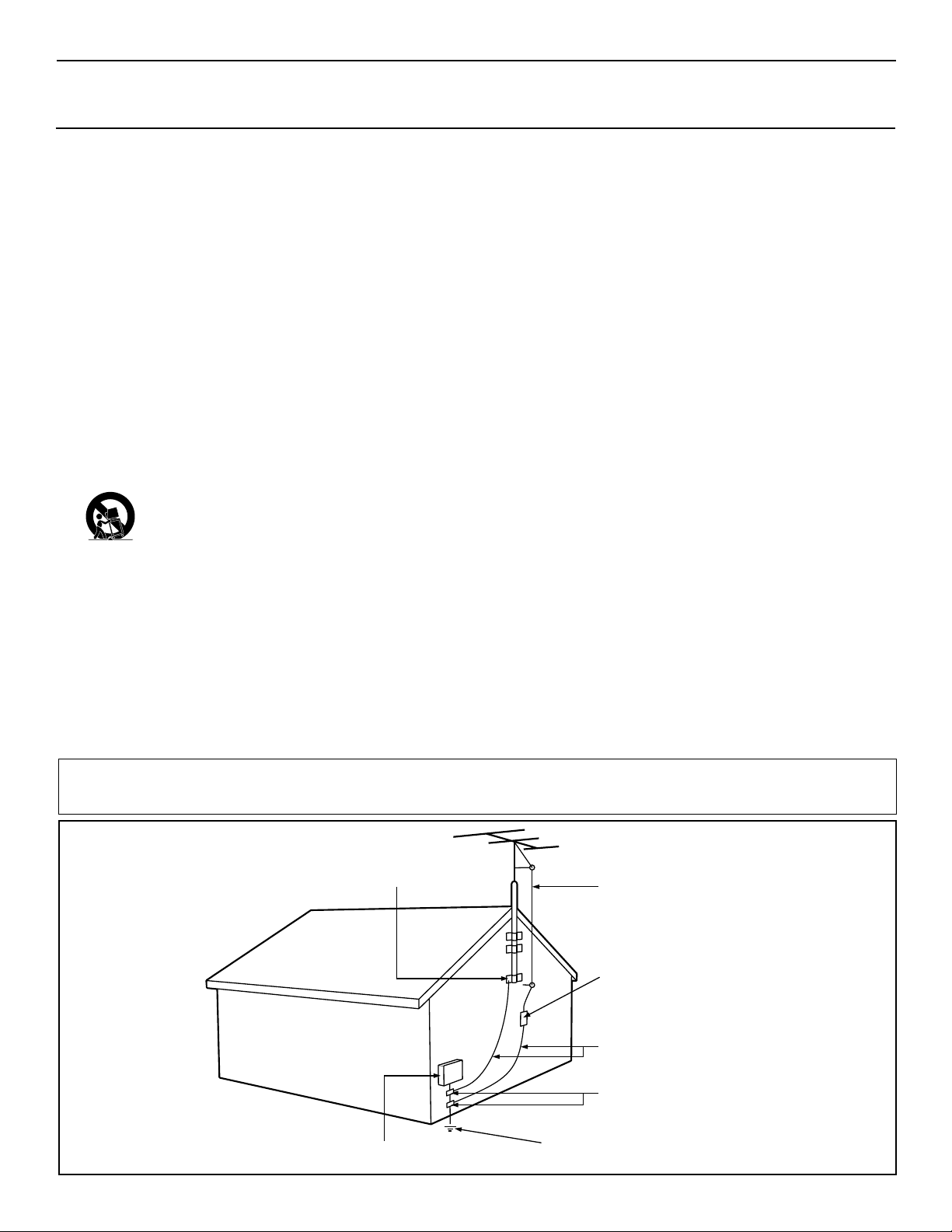
20. Outdoor Antenna Grounding - If an outside antenna is
connected to the receiver, be sure the antenna system is
grounded so as to provide some protection against voltage
surges and built up static charges.
Section 810 of the National Electric Code, ANSI/NFPANo.
70-1984, provides information with respect to proper
grounding of the mast and supporting structure, grounding
of the lead-in wire to an antenna discharge unit, size of
grounding connectors, location of antenna-discharge unit,
connection to grounding electrodes, and requirements for
the grounding electrode. See Figure below.
21. Object and Liquid Entry - Care should be taken so that
objects do not fall and liquids are not spilled into the enclosure through openings.
Example of Antenna Grounding
as per NEC - National Electric Code
Note to the CATV system installer: This reminder is provided to call the CATV system installer's attention to Article 820-40 of the NEC that provides
guidelines for proper grounding and, in particular, specifies that the cable ground shall be connected to the grounding system of the building, as close
to the point of cable entry as practical.
Rev. 8/13/01
GROUND CLAMP
ELECTRIC SERVICE EQUIPMENT
POWER SERVICE GROUNDING ELECTRODE SYSTEM (NEC ART 250, PART H)
ANTENNA LEAD IN WIRE
ANTENNA DISCHARGE UNIT
GROUNDING CONDUCTORS (NEC SECTION 810-21)
GROUND CLAMPS
(NEC SECTION 810-20)

Refer to the simple Quick Use and Setup Guide
(supplied with your TV) for details on the
following:
• Basic TV connections
• Television and remote-control operation
• Onscreen menu controls
• How to use the installation features.
Selecting the Stereo/Mono Sound Mode . . . . . . . . . . . . . .38
Selecting the SAP (Second Audio Program) Feature . . . . .39
Using the Bass Boost Control . . . . . . . . . . . . . . . . . . . . . .40
FEATURES
The Timer
Setting the Clock . . . . . . . . . . . . . . . . . . . . . . . . . . . . . . .41
Displaying the Time . . . . . . . . . . . . . . . . . . . . . . . . . . . .42
Setting the Timer’s Start Time and Stop Time . . . . . . . . .43
Selecting the Timer’s Channel . . . . . . . . . . . . . . . . . . . . .44
Setting the Timer’s Activate Control . . . . . . . . . . . . . . . .45
AutoLock™
Understanding AutoLock™ . . . . . . . . . . . . . . . . . . . . . . .46
Setting up the AutoLock™Access Code . . . . . . . . . . . . .47
Using AutoLock™ to Block Channels . . . . . . . . . . . . . . .48
Using AutoLock™ to Block by Movie Rating . . . . . . . . .49
Using AutoLock™ to Block by TV Rating . . . . . . . . . . .50
Turning the AutoLock™ Blocking Control
on or off . . . . . . . . . . . . . . . . . . . . . . . . . . . . . . . . . . . .51
Using AutoLock™ to Block Unrated Broadcasts . . . . . . .52
Using AutoLock™ to Block Broadcasts That
Have No Rating . . . . . . . . . . . . . . . . . . . . . . . . . . . . . . .53
Reviewing Your Currrent AutoLock™ Settings . . . . . . . .54
Using the Closed Captioning Control . . . . . . . . . . . . . . . . .55
Using the Picture-format Control . . . . . . . . . . . . . . . . .56–57
Using Active Control™ . . . . . . . . . . . . . . . . . . . . . . . . . . .58
APPENDIXES
Appendix A: Compatibility Information
for the TV’s High-definition Inputs . . . . . . . . . .59
Appendix B: Model Specifications . . . . . . . . . . . . . . . . . . .60
Appendix C: Setting Color Space for HD INPUT-AV 4 . . . .61
GENERAL INFORMATION
Care and Cleaning . . . . . . . . . . . . . . . . . . . . . . . . . . . . . . .62
Troubleshooting . . . . . . . . . . . . . . . . . . . . . . . . . . . . . .63–64
Glossary of Television Terms . . . . . . . . . . . . . . . . . . . . . . .65
Index . . . . . . . . . . . . . . . . . . . . . . . . . . . . . . . . . . . . . . . . .66
Factory Service Locations . . . . . . . . . . . . . . . . . . . . . .67–68
Limited Warranty . . . . . . . . . . . . . . . . . . . . . . . . . . . . . . . .72
CONTENTS
Items Included with This TV
As you unpack your TV, please note that this Directions for Use manual
contains safety-tip information, the locations of factory-service centers, a
warranty registration card, remote control, and batteries for the remote
control. Please take a few minutes to complete your registration card. The
serial number for the TV is on the rear of the set. Refer to page 62 for
cleaning and care instructions.
INTRODUCTION
Welcome/Registration of Your TV . . . . . . . . . . . . . . . . . . . .2
Safety/Precautions . . . . . . . . . . . . . . . . . . . . . . . . . . . . . .2–3
Features . . . . . . . . . . . . . . . . . . . . . . . . . . . . . . . . . . . . . . . .5
CONNECTING ACCESSORY DEVICES
TO
YOUR TV
Panel Overview: Standard Inputs and Outputs . . . . . . . . . . .6
Panel Overview: High-definition Inputs . . . . . . . . . . . . . . . .7
Connecting a VCR . . . . . . . . . . . . . . . . . . . . . . . . . . . . . . . .8
Connecting a VCR and Cable Box . . . . . . . . . . . . . . . . . . . .9
Connecting and Using an Audio Hi-fi System
with Your TV . . . . . . . . . . . . . . . . . . . . . . . . . . . . . . . . .10
Making Optional Surround-sound Connections . . . . . . . . .11
Connecting a Standard DVD Player . . . . . . . . . . . . . . . . . .12
Connecting an S-Video Device . . . . . . . . . . . . . . . . . . . . .13
Connecting a DVD Player with Progressive-scan
Capability . . . . . . . . . . . . . . . . . . . . . . . . . . . . . . . . . . . .14
Connecting an HD Receiver to the
HD INPUT-AV 4 Jacks . . . . . . . . . . . . . . . . . . . . . . . . . .15
Connecting a Camcorder . . . . . . . . . . . . . . . . . . . . . . . . . .16
Connecting and Using Headphones
with Your TV . . . . . . . . . . . . . . . . . . . . . . . . . . . . . . . . .17
USING THE REMOTE CONTROL
Programming the TV Remote to Work
with Accessory Devices . . . . . . . . . . . . . . . . . . . . .18
Using the Code-entry Method to Program Your
TV Remote . . . . . . . . . . . . . . . . . . . . . . . . . . . . . . . . . . .19
Using the Search Method to Program Your
TV Remote . . . . . . . . . . . . . . . . . . . . . . . . . . . . . . . . . . .20
Direct-entry Codes for A/VAccessory Devices . . . . . .21–22
Using the TV Remote with Accessory Devices . . . . . . . . .23
Using the AV and Source Select Buttons . . . . . . . . . . . . . .24
Using AutoSound™ . . . . . . . . . . . . . . . . . . . . . . . . . . . . . .25
Using AutoPicture™ . . . . . . . . . . . . . . . . . . . . . . . . . . . . .26
Using AutoSurf™ . . . . . . . . . . . . . . . . . . . . . . . . . . . . . . .27
Using Program List and Alternate Channel (A/CH) . . . . . .28
Using the Sleep Timer Control . . . . . . . . . . . . . . . . . . . . . .29
USING THE ONSCREEN SUBMENUS
PICTURE
Adjusting the Picture Controls . . . . . . . . . . . . . . .30
Setting the Eye Fidelity Control . . . . . . . . . . . . . . . . . . . . .31
Setting the Dynamic Contrast Control . . . . . . . . . . . . . . . .32
Adjusting the Manual Converge Controls:
Converge Red/Blue . . . . . . . . . . . . . . . . . . . . . . . . . . . . .33
Adjusting the Manual Converge Controls:
Multipoint Red/Blue . . . . . . . . . . . . . . . . . . . . . . . . . . . .34
SOUND
Adjusting the Treble, Bass, and
Balance Controls . . . . . . . . . . . . . . . . . . . . . . . .35
Using the AVL (Audio Volume Leveler) Control . . . . . . . .36
Selecting the Surround-sound Modes . . . . . . . . . . . . . . . . .37
QUICK USE AND SETUP GUIDE
4
POWER
ACC
TV
VCR
ACTIVE
FREEZE
SWAP PIP CH
CONTROL
DN
UP
PICTURE
SOUND
MENU/
STATUS/
SELECT
EXIT
ppendixes
BC
A
Important Notice/Warning . . . . . . . . . . . . . . . . . . . . . . . . . . . . . . . . . . . . . . . . . .1
Making Basic TVConnections . . . . . . . . . . . . . . . . . . . . . . . . . . . . . . . . . . . .1–2
Operating the Television and Remote Control . . . . . . . . . . . . . . . . . . . . . . . . .2–4
Using the Installation Features . . . . . . . . . . . . . . . . . . . . . . . . . . . . . . . . . . . . .4–7
Using Auto IntelliSense™to Adjust Picture Convergence . . . . . . . . . . . . . . . . . .7
Using the Picture-in-Picture (PIP) Feature . . . . . . . . . . . . . . . . . . . . . . . . . . . . . .8
he major benefit of this projection television is its large view-
T
ing screen. To see this large screen at its best, test various
locations in the room to find the optimal spot for viewing.
NOTE:Be sure to allow a free flow of air to and from the perforated back cover of the set.
C
f you are new to making TVhookups, you may want to read
I
this section. (The cables and connectors discussed are not supplied with your set. You can buy them at most stores that sell
audio or video products. Or call our Customer Care Center at
1-800-531-0039.)
This publication provides you with examples of basic connections.
See pages 6–17 in the Directions for Use manual for more information on connections, along with connection examples.
A75-ohm coaxial cableconnects signals
from an antenna or a cable TVcompany
to the antenna jack on the back of the TV.
Coaxial cables use “F” connectors.
Atwo-way signal splitterenables you to
take a single antenna or cable TVsignal
and supply it to two different inputs.
his section shows you how to make a basic TVconnection
using a cable TVor antenna signal.
T
If you have cable TVservice, you’ll simply connect the coaxial
cable lead-in from the cable TVcompany to your TV. If you intend
to connect a VHF/UHF antenna, you may need a 300- to 75-ohm
adapter, which is not supplied with your TV.
NOTE:You should be able to buy optional accessories such as a
VHF/UHF antenna or a 300- to 75-ohm adapter at most stores
that sell electr
at 1-800-531-0039.
Connect the Cable TVorantenna signal to the
ANTENNAIN 75
1
NOTE: If you are using an antenna with a round coaxial
cable (75Ω
the TV. If your antenna has a flat, twin-lead wire (300Ω),
you must first attach the antenna wires on a 300- to 75ohm adapter. Then push the round end of the adapter onto
the ANTENNAIN 75Ω
Insert the TV’s powerplug into the wall power outlet.
2
Quick Use and Setup Guide
Quick Use and Setup Guide
As an Ener
CONTENTS
Partner, Philips
Consumer Electronics
has determined this
product meets the
Energy Star®guidelines
for ener
Energy Star®is a U.S.
registered mark. Using
products with the Energy
Star®label can save
energy. Saving energy
reduces air pollution and
MAKINGBASIC TV CONNECTIONS
BESTVIEWING
To avoid cabinet warping, cabinet color changes,
and increased chance of set failure, do not place
the TVwhere temperatures can become excessively
hot—for example, in direct sunlight or near a
heating appliance.
A300- to 75-ohm twin-lead
ABLESAND CONNECTORS
adapteraccepts the antenna
cables (called twin-lead wires)
from an antenna, allowing you
to connect the antenna signal to
the TV.
Video and audio cables
with standard RCA
lowers utility bills.
(phono) connectors connect the video and audio
jacks of accessory
devices such as VCRs
and DVD players to the
jacks on the TV.
To simplify making connections, the connectors
are usually color coded. The jacks on your TVare
likewise color coded to match the colors of the
connectors. The coding is as follows: yellow for
video (composite) and red and white for the right
ANTENNAOR CABLETV
Coaxial Cable
Lead-in from
Cable TV Company
onics. Or you can call our Customer Care Center
OR
Ωjack on the rearof the TV.
), then you are ready to connect to the back of
jack on the rear of the TV.
300- to 75-ohm
Adapter
Twin-lead Wire
Coaxial Cable
Lead-in from Antenna
gy Star®
gy efficiency.
Coaxial Cable
IMPORTANT
NOTE: This owner's manual is used with several
different television models. Not all features (and
drawings) discussed in this manual will necessarily match those found with yourtelevision set.
This is normal and does not require that you contact yourdealerorrequest service.
WARNING: TO PREVENTFIRE OR SHOCK
HAZARD DO NOTEXPOSE THIS UNITTO
RAIN OR EXCESSIVE MOISTURE.
Magnetic fields, such as those of external speakers, may cause the picture to distort if the speakers are placed too close to the television. Move
the magnetic field source away from the TVuntil
there is no picture distortion.
and left audio channels, respectively. Use an audio
cable with a white connector when making mono,
or nonstereo, connections. The connectors of
video cables used to connect component video or
RGB (high-resolution) jacks are often color coded
red, green, and blue. Component video connections provide you with the highest possible color
and picture resolution.
An S-Video cableconnects
devices such as DVD players,
VCRs, or camcorders to your
ideo provides better picture performance
TV. S-V
than regular (composite) video connections.
S-Video cables can be used only with S-Videocompatible accessory devices. You must also connect the left and right audio cables along with SVideo because the S-V
picture signal, not the sound.
Cable TV
Company
ANTENNA IN 75Ω
VIDEO
S-VIDEO
L
L
AUDIO
R
Outdoor or Indoor Antenna
(Combination VHF/UHF)
The combination antenna receives normal
broadcast channels 2–13 (VHF) and 14–69 (UHF).
Rear-projection
Rear-projection
HDTV Monitor
HDTV Monitor
ideo jack carries only the
Rear of TV
1
AMP SWITCH
EXT INT
_
+
HD INPUT-AV 5
DVI
CENTER CHANNEL AMP INPUT
HD INPUT-AV 4
G/Y
R/Pr
INPUT-AV 2 SUBWOOFEROUTPUTINPUT-AV 1
Y
B/Pb
VIDEO
S-VIDEO
L
Pb
V
L
L
L
SYNC
AUDIO
AUDIO
AUDIO
Pr
H
R
R
R
3135 035 20561

5
FEATURES
Your new projection television and its packaging contain materials
that can be recycled and reused. Specialized companies can recycle your product to increase the amount of reusable materials and
minimize the amounts that need to be properly disposed. The batteries used by your product should not be thrown away when
depleted but should be handed in and disposed of as small chemical waste. Please find out about the local regulations concerning
how to dispose of your old television, batteries, and packaging
materials whenever it is time to replace them.
End-of-life Disposal
Philips HD Optics System answers the demand for extreme-resolution HD with cutting-edge processing and display technology,
including micro-phosphor CRTs, hybrid projection lenses, first-surface mirrors, fine-pitched lenticular lenses, and a Philips wideband
video amplifier.
Auto IntelliSense™ Focus automatically adjusts picture convergence at the push of a button. After reviewing a special test pattern, optical sensors send position information to the controller,
which then corrects the pictures. Auto IntelliSense™ Focus
responds to the natural and man-made magnetic field conditions
where the TV is located, so you will always enjoy the best possible
picture.
Automatic Phosphor Aging Compensation (APAC) works with
the set’s Automatic Format feature to prevent screen burn left by
nonmoving images. Periodically, APAC automatically shifts your
television picture in very small increments, but in increments large
enough to blur image retention. APAC is like a screen saver for
your TV.
Active Control™ continuously measures and corrects all incoming
signals to provide the best picture settings. This feature provides a
sharp and virtually noise-free picture any time, from any NTSC
source. NTSC is the
National Television Standards Committee format devised in the 1940s for TV broadcast analog video signals
(525 lines: 30 Hz).
Eye Fidelity gives you a choice between two different picturescanning techniques—progressive and interlaced. Progressive scan
doubles the number of visible picture lines per field by displaying
all picture frame lines at once, eliminating line flicker. The interlaced mode provides for a double vertical display (interlaced) of
progressive scan, which reduces annoying motion artifacts. The
Interlaced mode also helps smooth out jagged lines sometimes
seen on curved and angled surfaces.
Protective screen filter helps prevent accidental damage to the
delicate front lenticular screen. This filter has been specifically formulated by Philips for HD displays to give the best possible picture and still protect your investment.
High-definition component and (digital visual interface) DVI
inputs support HD video input for superb color purity, crisp color
detail, and reduced color noise. Included are inputs for Y, Pb, Pr,
and horizontal and vertical sync, plus DVI.
3-D Y/C Digital Comb Filter (activated when using the tuner and
composite inputs) processes the video with spatial and temporal
filtering, virtually eliminating cross-color and cross-luminance
interference, improving video resolution. This filter uses extensive
memory to analyze complete video fields, significantly reducing
“dot crawl,” “hanging dots,” and “barber pole artifacts” on the
image.
Double-window, two-tuner Picture-in-Picture (PIP) allows you
to watch two shows, side by side. No VCR is necessary for tuning
PIP pictures. Your set’s two separate tuners let you select two
shows and display both in windows of equal proportion.
Virtual Dolby* Surround (referred to as DOLBY VIRTUAL in
the onscreen submenu) uses two speakers to simulate the sur-
round effect produced by a multichannel system.
Incredible Surround™ enhances stereo programs by making the
sound broader and fuller.
Center channel input, which has standard clip-on style speaker
connectors, simplifies the connection of surround-sound equipment
for optimal home-theater enjoyment. Since it contains the dialog
information, the center channel is vitally important to the overall
performance of any large screen in a home-theater system.
Home-cinema universal remote control operates your TV set and
other devices that work by infrared remote control, such as VCRs,
cable converter boxes, satellite receivers, and others. Note: You
may need to program the remote to work with devices other than
the TV. See pages 18–23.
Hi-fi stereo system, including a built-in audio amplifier and a twin
speaker system with 2-inch tweeters and 5-inch woofers. The system enables you to hear stereo sound or Second Audio Program
(SAP) bilingual broadcasts when they are available.
Audio/video jacks allow direct connections with VCRs and other
accessories for quality TV picture and sound playback. Component
video input jacks are provided for high-fidelity color and picture
resolution when using digital video source material, such as a DVD.
Audio Volume Leveler (AVL) control keeps the TV’s sound at an
even level. Peaks and valleys that occur during program changes or
commercial breaks are reduced, making for a more consistent, comfortable sound.
AutoChron™ automatically sets the right time of day and maintains it with digital precision through brownouts, power failures,
and even Daylight Savings Time adjustments.
AutoLock™ protects young children from objectionable programming with V-chip technology.
AutoSound™ allows you to select from three factory-set controls
and a personal control that you set according to your own preferences through the onscreen Sound submenu. The three factory-set
controls—Voice, Music, and Theatre—enable you to tailor the TV
sound to enhance the particular programming you are watching.
AutoSurf™ allows you to easily switch among only the channels
that are of interest to you. You can program up to 10 channels into
the TV’s AutoSurf™ memory through the onscreen display.
Channel Edit allows you to add or remove channels from the list
of channels stored in the TV’s memory. Channel Edit makes it easy
to limit or expand the number of channels that are available to you
when you press the CH +/– buttons on your remote control.
Closed Captioning allows you to read TV program dialog or voice
conversations as onscreen text.
Dynamic Contrast helps sharpen the picture quality by making the
contrast between the dark and bright picture areas more noticeable
as the image on screen changes.
As an Energy Star® Partner, Philips Consumer Electronics has
determined this product meets the Energy Star® guidelines for
energy efficiency. Energy Star® is a U.S. registered mark. Using
products with the Energy Star® label can save energy. Saving
energy reduces air pollution and lowers utility bills.
Active Control, APAC, AutoPicture, AutoSound, AutoSurf, Incredible
Surround, and IntelliSense are trademarks of Philips Consumer Electronics
North America. Copyright 2002 Philips Consumer Electronics.
*Manufactured under license from Dolby Laboratories. “Dolby” and the
double-D symbol are trademarks of Dolby Laboratories.
6
Connecting Accessory Devices to Your TV
Y
ou can connect a wide range of video and
audio devices to your TV, in various ways.
This page and the next one provide an overview
of signal compatibilities and the types of
devices you can connect to the jacks.
Connection examples follow on subsequent
pages. See pages 1 and 2 of the Quick Use and
Setup Guide that came with your set for examples of basic connections. You may also want to
refer to the user instructions that came with
each particular device for information on connections.
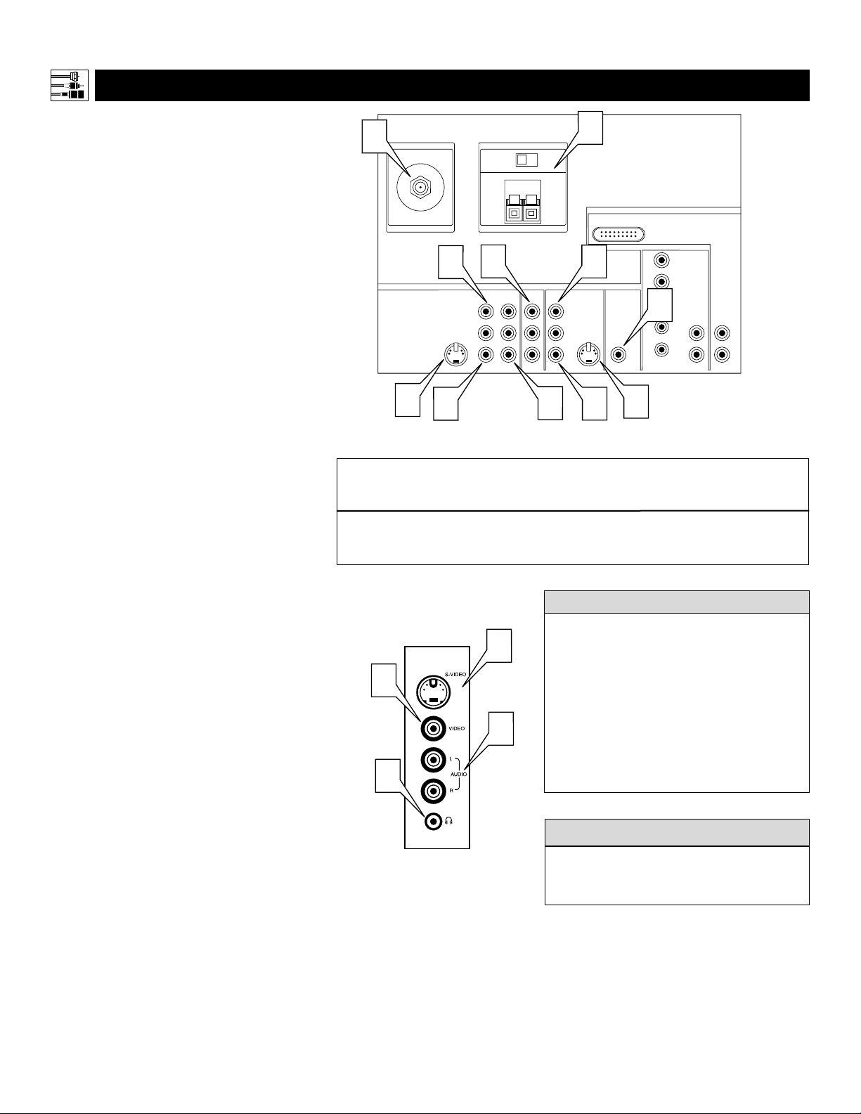
What You Can Connect to the
Standard Panel Jacks
1
ANTENNA IN 75Ω jack—use to connect radio-frequency (RF) signals from
VHF/UHF antennas or a cable system.
These are 480i signals.
2
YPbPr (component video input [CVI]
jacks)—compatible with 480i signals
only. Use to connect accessories having
component video outputs, such as DVD
players, laser-disc players, video-game
players, satellite receivers, or other
devices. Use the INPUT-AV 1 L(eft) and
R(ight) AUDIO jacks for sound connections. CVI is not accessible in the PIP
window.
3
S-VIDEO (super video) jacks—compatible with 480i signals only. Use to
connect accessories having Super VHS
(S-VHS) outputs, such as VCRs, DVD
players, laser-disc players, video-game
players, satellite receivers, or other
devices.
4
VIDEO (composite) jacks (INPUT-AV
1,
INPUT-AV 2, and TV’s side jack panel
[AV3])—compatible with 480i signals
only. Use to connect accessories having
composite video outputs, such as VCRs,
video-game players, or other devices.
5
AUDIO inputs (INPUT-AV 1,
INPUT-AV 2, and TV’s side jack panel
[AV3])—use to connect from the audio
output jacks on VCRs, DVDs, or other
accessories.
6
OUTPUT (VIDEO/AUDIO)—video is
compatible with 480i signals only. Use to
connect to a VCR to record programs
from the TV. Or use the AUDIO outputs
to connect to an audio hi-fi system.
7
AMP SWITCH, CENTER
CHANNELAMPINPUT, and
SUBWOOFER Output—use to make
optional surround-sound connections
(see page 11).
8
n Headphone jack—use to connect
headphones for personal listening.
PANEL OVERVIEW
:STANDARD INPUTS AND OUTPUTS
The side jack-panel inputs (recognized by the
TV as AV3) are convenient for connecting a
camcorder. See page 16.
cc
C
HECK IT OUT
Summary of signal compatibilities
TV Input
Compatible output signal
from an external source
or device
ANTENNA IN 75Ω,INPUT A V -1,YPbPr
(component video inputs [CVI]),
INPUT AV-2,and side jack panel (AV3)
480i (480 lines,interlaced)
Signal sources connected to the
HD INPUT-AV 4 or HD INPUT-AV 5 jacks
will provide the best picture (see page 7 for
descriptions of those inputs). Among the
standard (480i-compatible) inputs—
ANTENNA IN 75Ω, INPUT AV-1, CVI
[labeled Y, Pb, Pr], INPUT AV-2, and the
side jack panel [AV3])—the best picture
will come from signal sources connected to
the CVI jacks. S-Video will provide the
next-best level of picture quality.
HELPFUL HINTS
ANTENNA IN 75Ω
1
4
VIDEO
S-VIDEO
L
3
5
Side Jack Panel
AMP SWITCH
EXT INT
+
CENTER CHANNEL AMP INPUT
6
INPUT-AV 1
Y
Pb
L
AUDIO
Pr
R
3
4
G
5
8
NOTE: The
TV recognizes
the side jack
panel as AV3.
7
_
DVI
4
INPUT-AV 2 SUBWOOFEROUTPUT
VIDEO
S-VIDEO
L
L
AUDIO
R
2
3
5
Rear of TV
HD INPUT-AV 5
HD INPUT-AV 4
G/Y
R/Pr
B/Pb
7
V
L
SYNC
AUDIO
H
R
AUDIO
L
R

7
Connecting Accessory Devices to Your TV
PANEL OVERVIEW
:HIGH-DEFINITION INPUTS
What You Can Connect to the
High-definition Input Jacks
1
HD INPUT-AV 4—use to connect digital equipment with a 1080i or a 480p
signal output, such as HD receivers
(1080i or 480p) or DVD players with
progressive-scan capability (480p). You
can connect equipment with YPbPr
component video or RGB outputs to
the HD INPUT-AV 4 jacks. H and V
sync connections may or may not be
required for RGB connections. (See
page 59.) Dedicated audio input jacks
are located with the HD INPUT-AV 4
video jacks.
NOTE: The Picture-in-Picture (PIP)
feature is not available for use with AV 4.
2
HD INPUT-AV 5—use to connect digital equipment with DVI (digital visual
interface) 1080i or 480p output. DVI is
a specific digital input allowing
encrypted transmission of uncompressed HD content. DVI includes
HDCP (high-bandwidth digital content
protection), which is supported by
Hollywood, satellite providers, and
most of the consumer electronics industry. DVI is gaining momentum and
quickly becoming an industry standard
for the consumer to view high-definition
material while keeping content protected.
NOTE: The Picture-in-Picture (PIP)
feature is not available for use with AV5.
Summary of signal compatibilities
TV Input
Compatible output signal
from an external source
or device
HD INPUT-AV 4
1080i (1080 lines,interlaced) or
480p (480 lines,progressive scan)
• The TV’s default color-space setting for HD
INPUT-AV 4 is YPbPr. If the picture looks
grossly incorrect, try changing the color-space
setting on either the digital equipment or the
TV. For more information on setting the color
space on the digital equipment, see the equipment’s directions-for-use manual. To set the
TV’s color space, see page 61 in this manual.
• This television is designed to be compatible
with high-definition signal standards 1080i
and 480p as specified by the Electronic
Industries Association standard EIA770.3.
Because output standards may vary by manufacturer, you may encounter some digital
equipment that will not properly display pictures on the TV.
• The Picture-in-Picture (PIP) feature does not
function with the HD INPUT-AV 4 or
HD INPUT-AV 5 signal sources. AV4 and
AV5 cannot be displayed in the PIP window,
nor can the PIP window be displayed when
either AV4 or AV5 is being viewed on the
main screen.
HELPFUL HINTS
HD INPUT-AV 5
Digital visual interface (DVI) with
1080i (1080 lines,interlaced) or
480p (480 lines,progressive scan)
ANTENNA IN 75Ω
VIDEO
S-VIDEO
L
AMP SWITCH
EXT INT
+
CENTER CHANNEL AMP INPUT
INPUT-AV 1
L
AUDIO
R
_
Y
Pb
Pr
Rear of TV
HD INPUT-AV 5
HD INPUT-AV 4
G/Y
R/Pr
B/Pb
V
SYNC
H
L
AUDIO
R
INPUT-AV 2 SUBWOOFEROUTPUT
AUDIO
VIDEO
L
R
S-VIDEO
DVI
L
2
1
AUDIO
L
R
8
PIP ON/OFF
213
546
879
0
TV
SWAP PIP CH
DN
UP
ACTIVE
CONTROL
FREEZE
SOUND
MUTE
SURF
A/CH
POWER
PICTURE
STATUS/
EXIT
SURF
ITR/
HOME
HOME
PERSONAL
SLEEP
REC •
VCR
ACC
MENU/
SELECT
VOL
CH
TV/VCR
FORMAT
SAP
PROG.LISTDOLBY VAV
5
AV1
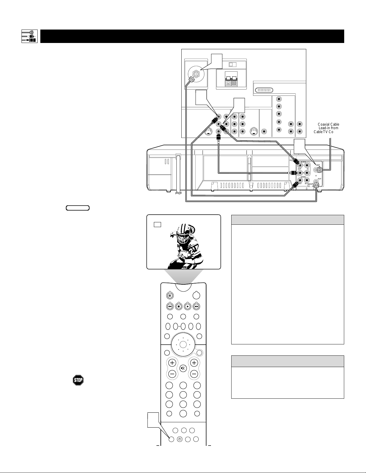
T
he TV’s audio/video (AV) input jacks provide
for direct picture and sound connections
between the TV and accessory devices such as
VCRs, DVD players, and others that have AV output jacks.
This example, which uses the INPUT-AV 1 jacks,
shows you one way you can connect a VCR to
your TV.
Refer to the directions-for-use manual for your
VCR for further information on connections.
To make the connections shown in this example,
you will need:
• one coaxial cable (75Ω)
• one cable for a video connection (standard
RCA connector)
• two cables for audio connections (standard
RCA connectors) (only one cable is needed for
a nonstereo VCR).
NOTE: The cables are not supplied with your TV.
You should be able to buy them at most stores
that sell electronics. Or you can call our
Customer Care Center at 1-800-531-0039.
1
Connect a cable TV or antenna signal to
the ANT IN jack on the rear of the VCR.
2
Connect from the OUT jack on the rear
of the VCR to the
ANTENNA IN 75Ω
jack on the rear of the TV.
3
Connect the VIDEO OUT jack on the
rear of the VCR to the INPUT AV1
VIDEO jack on the rear of the TV.
4
Connect the audio output R(ight) and
L(eft) jacks on the rear of the VCR to the
INPUT-AV 1 AUDIO jacks on the rear of
the TV.
NOTE: If the VCR is a mono (nonstereo)
unit, connect only the left audio cable,
which usually has a white connector.
5
Press the AV button on the remote control as many times as necessary to select
the AV1 source.
6
Turn the VCR on and press PLAY to
view a videotape on the TV.
Connecting Accessory Devices to Your TV
CONNECTING A VCR
BEGIN
To simplify making connections, audio and
video cables often have color-code connectors. The jacks on your TV are likewise
color coded to match the connectors. The
coding is as follows:
• Yellow for video (composite)
• Red for the right audio channel
• White for the left audio channel
NOTE: If your VCR is mono (nonstereo), you will connect only one audio
cable. You must ensure that the TV is set
to MONO for the signal source to which
you’ve connected the VCR (
INPUT-AV
1,
INPUT-AV2, or the side panel inputs
[AV3]). Otherwise, you will receive
sound from only one of the TV’s speakers.
See page 38.
HELPFUL
HINT
Y ou can display the A V1, AV2, or A V3 signal
sources in the PIP window. See page 8 of the
Quick Use and Setup Guide for information on
using the Picture-in-Picture (PIP) feature.
cc
C
HECK IT OUT
ANTENNA IN 75Ω
2
CENTER CHANNEL AMP INPUT
3
VIDEO
S-VIDEO
L
L
AUDIO
R
Rear of VCR*
* (Example: Philips VCR
model VR674CAT)
AMP SWITCH
EXT INT
+
Y
Pb
Pr
4
Rear of TV
_
HD INPUT-AV 5
DVI
HD INPUT-AV 4
G/Y
R/Pr
B/Pb
V
L
L
SYNC
AUDIO
H
R
AUDIO
R
Cable TV Company
or VHF/UHF Antenna
Coaxial Cable
Lead-in from
AUDIO
INPUT-AV 2 SUBWOOFEROUTPUTINPUT-AV 1
VIDEO
S-VIDEO
L
L
R
1
AUDIO
L
ANT
IN
IN
OUT
R
VIDEO
OUT
CH3 CH4
IN
OUT
9
CONNECTING A VCR
AND CABLE BOX
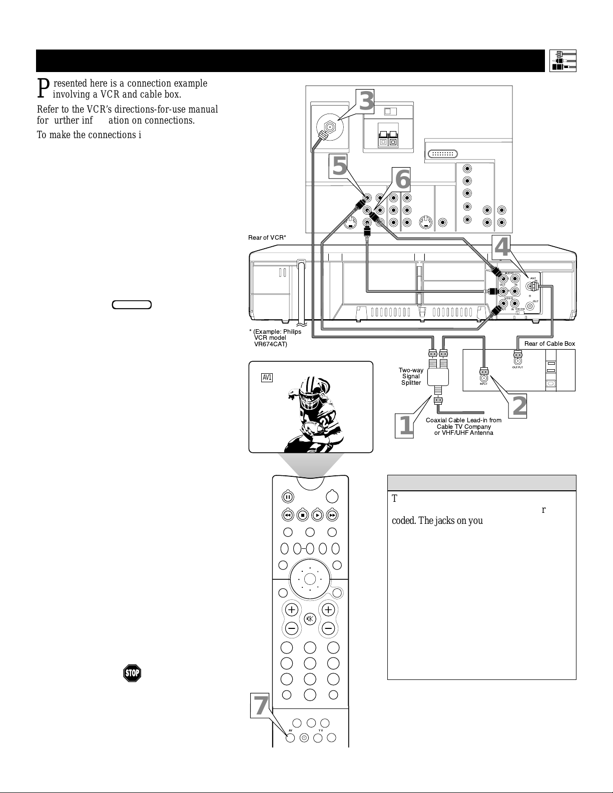
P
resented here is a connection example
involving a VCR and cable box.
Refer to the VCR’s directions-for-use manual
for further information on connections.
To make the connections in this example, you
will need:
• one, two-way signal splitter
• two coaxial cables (75Ω)
• one cable for a video connection (standard
RCA connector)
• two cables for audio connections (standard
RCA connectors) (only one cable is needed
for connection to a nonstereo VCR).
NOTE: The cables are not supplied with your
TV. You should be able to buy them at most
stores that sell electronics. Or you can call
our Customer Care Center at
1-800-531-0039.
1
Connect a cable TV signal to a twoway signal splitter.
2
Connect one of the two-way signal
splitter outputs to the INPUT on the
cable box.
3
Connect the other two-way signal
splitter output to the ANTENNAIN
75Ω on the rear of the TV.
4
Connect from the cable box OUTPUT
jack to the ANT IN jack on the rear of
the VCR.
5
Connect the VIDEO OUT jack on
the VCR to the INPUT-AV 1 VIDEO
jack on the rear of the TV.
6
Connect the AUDIO OUT R(ight)
and L(eft) jacks on the VCR to
INPUT-AV 1 AUDIO jacks on the rear
of the TV.
NOTE: If the VCR is a nonstereo unit,
connect only the left audio cable,
which usually has a white connector.
7
Press the AV button on the remote
control as many times as necessary
to select the AV1 source.
8
Turn the VCR on and push PLAY to
view a videotape.
Connecting Accessory Devices to Your TV
BEGIN
To simplify making connections, the connectors
on audio and video cables are often color
coded. The jacks on your TV are likewise color
coded to match the connectors.
The coding is as follows:
• Yellow for video (composite)
• Red for the right audio channel
• White for the left audio channel
NOTE: If your VCR is mono (nonstereo),
you will connect only one audio cable. You
must ensure that the TV is set to MONO for
the signal source to which you’ve connected
the VCR (INPUT-AV 1, INPUT-AV 2, or the
side panel inputs [AV3]). Otherwise, you will
receive sound from only one of the TV’s
speakers. See page 38.
HELPFUL HINT
Rear of VCR*
* (Example: Philips
VCR model
VR674CAT)
AV1
ANTENNA IN 75Ω
AMP SWITCH
3
EXT INT
+
CENTER CHANNEL AMP INPUT
_
5
INPUT-AV 2 SUBWOOFEROUTPUT
6
Y
Pb
AUDIO
Pr
Two-way
Signal
Splitter
S-VIDEO
L
INPUT-AV 1
VIDEO
L
AUDIO
R
1
Rear of TV
HD INPUT-AV 5
DVI
HD INPUT-AV 4
VIDEO
S-VIDEO
L
L
R
Coaxial Cable Lead-in from
Cable TV Company
or VHF/UHF Antenna
G/Y
R/Pr
B/Pb
V
L
AUDIO
L
AUDIO
R
R
SYNC
H
4
AUDIO
L
ANT
IN
IN
OUT
R
VIDEO
OUT
CH3 CH4
IN
OUT
Rear of Cable Box
OUTPUT
INPUT
2
7
TV
VCR
SWAP PIP CH
DN
UP
SOUND
STATUS/
EXIT
VOL
MUTE
213
546
879
TV/VCR
A/CH
0
SURF
REC •
FORMAT
SAP
ITR/ HOME HOME PERSONAL
ACTIVE
CONTROL
PIP ON/OFF
SLEEP
POWER
ACC
FREEZE
PICTURE
MENU/
SELECT
CH
SURF
PROG.LISTDOLBY VAV
10
CONNECTING AND U
SING AN AUDIO HI-FI SYSTEM WITH YOUR TV
Y
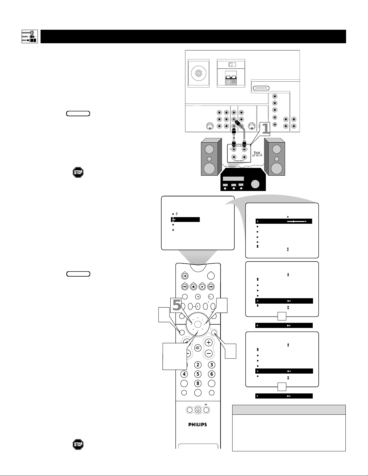
ou can use your TV’s AUDIO OUTPUT jacks
to connect to an external audio hi-fi system.
Follow the simple steps below.
To make these connections, you will need two
cables for audio connections (standard RCA).
NOTE: The cables are not supplied with your TV.
You should be able to buy them at most stores
that sell electronics. Or you can call our
Customer Care Center at 1-800-531-0039.
1
Connect from the L(eft) and R(ight)
AUDIO OUTPUT jacks on the rear of the
TV to the L(eft) and R(ight) AUX/TV
INPUT jacks on the rear of the hi-fi system.
2
See the section below on using the
AUDIO OUT control.
A
fter connecting the TV’s AUDIO OUTPUT
jacks to the AUDIO INPUT jacks on an
external hi-fi system, set the AUDIO OUT
control in the SOUND submenu to either
VARIABLE or FIXED to determine whether
you adjust the volume at the TV or at the
external hi-fi system. To change the volume at
the TV using the TV’s remote control, you must
select VARIABLE. To adjust the volume at the
stereo using the hi-fi’s controls, you must select
FIXED. You can also use the SPEAKERS
control in the SOUND submenu to turn the
TV’s speakers off.
1
Press the MENU/SELECT button
on the remote control to show the
onscreen menu.
2
Press the CURSOR RING DOWN
once to highlight SOUND.
3
Press the CURSOR RING RIGHT
to enter the SOUND submenu.
4
Press the CURSOR RING DOWN
repeatedly until AUDIO OUT is highlighted.
5
Press the CURSOR RING LEFT or
RIGHT to set the AUDIO OUT to
either VARIABLE or FIXED.
6
If you want to turn the TV’s internal
speakers off, press the CURSOR
RING DOWN repeatedly until
SPEAKERS is highlighted. Then press
the CURSOR RING LEFT or RIGHT
to turn the speakers off.
7
Press the STATUS/EXIT button to
exit the menu.
Connecting Accessory Devices to Your TV
BEGIN
BEGIN
The sound outputs from the TV to an external hi-fi system are not affected or tailored
by the TREBLE, BASS, BALANCE, AVL,
INCR. SURROUND, and BASS BOOST
controls in the TV’s SOUND submenu.
HELPFUL HINT
S-VIDEO
L
VIDEO
AUDIO
AMP SWITCH
EXT INT
+
CENTER CHANNEL AMP INPUT
INPUT-AV 1
L
R
Rear of TV
_
HD INPUT-AV 5
DVI
HD INPUT-AV 4
G/Y
INPUT-AV 2 SUBWOOFEROUTPUT
Y
VIDEO
S-VIDEO
Pb
Pr
L
L
AUDIO
R
R/Pr
B/Pb
V
L
SYNC
H
L
AUDIO
AUDIO
R
R
ANTENNA IN 75Ω
1
AUX/TV INPUT
L
PICTURE
SOUND
FEATURES
INSTALL
R
PHONO INPUT
TREBLE
BASS
BALANCE
AVL
INCR . SURROUND
POWER
Rear
of Hi-fi
SOUND
TREBLE 30
BASS
BALANCE
AVL
INCR . SURROUND
SOUND
5
7
2, 4,
6
SWAP PIP CH
SOUND
STATUS/
EXIT
VOL
TV/VCR
A/CH
TV
VCR
ACTIVE
CONTROL
DN
UP
MUTE
213
546
879
0
POSITION
PIP
ACC
SURF
FREEZE
PICTURE
MENU/
SELECT
INCR . SURROUND
HEADPHONE
STEREO
SAP
AUDIO OUT FIXED
3
OR
AUDIO OUT VARIABLE
SOUND
CH
1
HEADPHONE
STEREO
SAP
AUDIO OUT
SPEAKERS OFF
OR
SPEAKERS ON
MAKING OPTIONAL SURROUND-SOUND CONNECTIONS
Connecting Accessory Devices to Your TV
*“Dolby”, “Pro Logic”, and the double-D symbol are
trademarks of Dolby Laboratories.
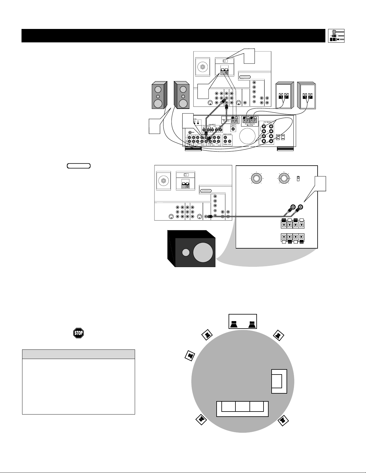
Y
our TV has extra jacks that allow you to con-
nect to an external audio amplifier system and
a powered subwoofer. This connection option will
provide a surround-sound experience similar to a
movie theater or concert hall.
To make the connections shown in this example,
you will need:
•
two cables for audio connections (standard
RCA connectors)
• four paired wires for speaker connections
• one cable for a subwoofer connection
(standard RCA connectors).
NOTE: The cables are not supplied with your TV.
You should be able to buy them at most stores
that sell electronics. Or you can call our
Customer Care Center at 1-800-531-0039.
1
Connect from the Center Speakers output jacks on the amplifier with Dolby Pro
Logic* or Dolby Digital to the corresponding CENTER CHANNEL INPUT jacks on
the rear of the TV. Place the TV’s AMP
switch in the EXT (external) position.
2
Connect from the L(eft) and R(ight)
AUDIO OUTPUT jacks on the rear of the
TV to the L(eft) and R(ight) TV IN jacks on
the rear of the Dolby receiver.
3
Connect from the receiver’s fr ont and
surround speaker connectors to the front
and rear surround speakers.
4
Connect from the SUBWOOFER output
jack on the rear of the TV to the L(eft) and
R(ight) Low Level Input jacks on the rear of
the powered subwoofer.
5
Set the TV’s AUDIOOUT control to
FIXED. See page 10.
The diagram below, right shows how to arrange the
speakers and subwoofer for surround sound.
BEGIN
• If you use a single cable to make the connection to the powered subwoofer, you will need
to increase the volume on the back of the
subwoofer to compensate for the absence of
the second cable.
• You must adjust the trim of the powered subwoofer at the powered subwoofer. Trim refers
to the fine adjustments of volume level.
H
ELPFUL HINTS
11
Front Speakers
3
ANTENNA IN 75Ω
2
AMP SWITCH
EXT INT
_
+
CENTER CHANNEL AMP INPUT
Y
VIDEO
S-VIDEO
Pb
L
L
AUDIO
Pr
R
Powered Subwoofer
ANTENNA IN 75Ω
1
Rear of Amplifier with Dolby Pro Logic or Dolby Digital
INPUT-AV 2 SUBWOOFEROUTPUTINPUT-AV 1
VIDEO
S-VIDEO
L
L
AUDIO
R
NOTE: The gray circle indicates the primary viewing area.
Speaker
AMP SWITCH
EXT INT
_
+
CENTER CHANNEL AMP INPUT
Y
VIDEO
S-VIDEO
Pb
L
L
AUDIO
Pr
R
Rear of TV
HD INPUT-AV 5
DVI
HD INPUT-AV 4
G/Y
R/Pr
B/Pb
V
L
L
SYNC
AUDIO
AUDIO
H
R
R
Surround-sound Setup
(Center Speakers)
Front
1
Rear of TV
HD INPUT-AV 5
DVI
HD INPUT-AV 4
G/Y
INPUT-AV 2 SUBWOOFEROUTPUTINPUT-AV 1
VIDEO
S-VIDEO
L
L
AUDIO
R
R/Pr
B/Pb
V
L
SYNC
AUDIO
H
R
Rear of Powered Subwoofer
90
150 Hz
Crossover
Frequency
TV
L
AUDIO
R
Front
Speaker
Rear Speakers
+-
110
Volume
R
+ R – – L +
-180
Phase
0
L
+
-
o
o
4
Low
Level
Input
High
Level
Input
High
Level
Output
Powered
Subwoofer
Rear
Speaker
Rear
Speaker
12
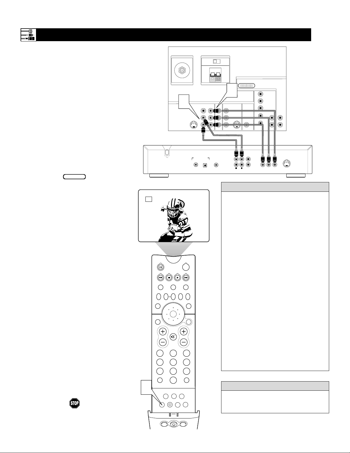
CONNECTING A STANDARD DVD PLAYER
C
omponent video inputs allow the highest pos-
sible color and picture resolution in the playback of digital signals, such as those of DVD
players. The color difference signals (Pb, Pr) and
the luminance (Y) signal are connected and
received separately. The result is better color
bandwidth information than is possible with composite video (labeled VIDEO on your TV’s jack
panel) or S-Video connections.
To make the connections shown in this example,
you will need:
• three cables for video connections (standard
RCA connectors)
• two cables for audio connections (standard
RCA connectors).
NOTE: The cables are not supplied with your TV.
You should be able to buy them at most stores
that sell electronics. Or you can call our
Customer Care Center at 1-800-531-0039.
1
Connect the YPbPr (component)
VIDEO OUT jacks from the DVD player
to the INPUT-AV 1 YPbPr (component
video) jacks on the rear of the TV.
NOTE: The INPUT -AV 1 YPbPr jacks
will accept 480i (interlaced) output signals only.The connection example on this
page assumes the use of a DVD player
with interlaced output. Some DVD players, however, have YPbPr outputs that can
be switched between interlaced and progressive scan. If you are attempting to use
a DVD player with progressive-scan
(480p output) capability to make the connection shown in this example, you must
be sure to switch the DVD player to interlaced. If necessary, refer to the DVD player’s directions-for-use manual for help. If
you want to use the DVD player in progressive-scan mode, you must use the
HD INPUT-AV 4 jacks (see page 14).
2
Connect the AUDIOOUT L(eft) and
R(ight) jacks from the DVD player to the
INPUT-AV 1 AUDIO jacks on the rear of
the TV.
3
Press the AV button on the remote control as many times as necessary to select
the CVI (component video input) source
on the TV.
4
Turn the DVD player on and press
PLAY to view the DVD program on
the TV.
Connecting Accessory Devices to Your TV
• To simplify making connections, the connectors on audio and video cables are often
color coded. The jacks on your TV are likewise color coded to match the connectors.
• The names for the component video jacks
may differ depending on the DVD player or
accessory digital source equipment used.
For example, besides YPbPr, you may see
R-Y/B-Y/Y; or CrCbY. Although abbreviations and terms may vary, the letters Band
R stand for the blue and red color component signal connectors, respectively, and Y
indicates the luminance signal. If necessary,
refer to the directions-for-use manual for
your DVD or digital accessory for more
information.
• You can also connect a satellite receiver to
the TV in a manner similar to the example
shown on this page. If you connect a satellite receiver to the TV, you will need to use
the receiver’s channel-memorization system
to store channels in the receiver’s memory.
• If you experience difficulties receiving
sound with a DVD disc, check the sound
settings through the DVD disc’s menu.
• CVI is not accessible in the PIP window.
See page 8 in the Quick Use and Setup
Guide for more on the PIP feature.
HELPFUL HINTS
To prevent uneven picture-tube aging, do not
leave nonmoving images or picture borders on
the screen for an extended period. See page 62.
WARNING
BEGIN
ANTENNA IN 75Ω
2
S-VIDEO
L
Rear of DVD Player*
PCM-MPEG2-Dolby Digital-DTS
COAXIAL
*(Example: Philips DVD model DVD712)
CVI
POWER
ACC
VCR
ACTIVE
CONTROL
FREEZE
UP
PICTURE
MENU/
SELECT
MUTE
CH
213
546
879
SURF
0
PIP ON/OFF
SLEEP
FORMAT
PROG.LISTDOLBY VAV
HOME
PERSONAL
MOVIES
PIPPOSITION
3
TV
SWAP PIP CH
SOUND
STATUS/
EXIT
VOL
TV/VCR
A/CH
ITR/
RECORD
DN
SURF
REC •
SAP
HOME
VIDEO
CENTER CHANNEL AMP INPUT
INPUT-AV 1
VIDEO
L
AUDIO
R
DIGITAL AUDIO OUT
OPT OUT
AMP SWITCH
EXT INT
+
Y
Pb
Pr
SUB WF OUT
_
1
INPUT-AV 2 SUBWOOFEROUTPUT
VIDEO
S-VIDEO
L
L
AUDIO
R
1
2
R
AUDIO OUT
Rear of TV
HD INPUT-AV 5
DVI
HD INPUT-AV 4
G/Y
R/Pr
B/Pb
V
SYNC
H
1
2
PR/C
L
VIDEO OUT
R
(CVBS)
VIDEO OUT
AUDIO
L
L
AUDIO
R
R
Y
B/CB
P
(Y/C)
S-VIDEO OUT
PIP ON/OFF
213
546
879
0
TV
SWAP PIP CH
DN
UP
ACTIVE
CONTROL
FREEZE
SOUND
MUTE
SURF
A/CH
POWER
PICTURE
STATUS/
EXIT
SURF
ITR/
RECORD
HOME
VIDEO
HOME
MOVIES
PERSONAL
SLEEP
REC •
VCR
ACC
MENU/
SELECT
VOL
CH
TV/VCR
FORMAT
SAP
PROG.LISTDOLBY VAV
3
AV2
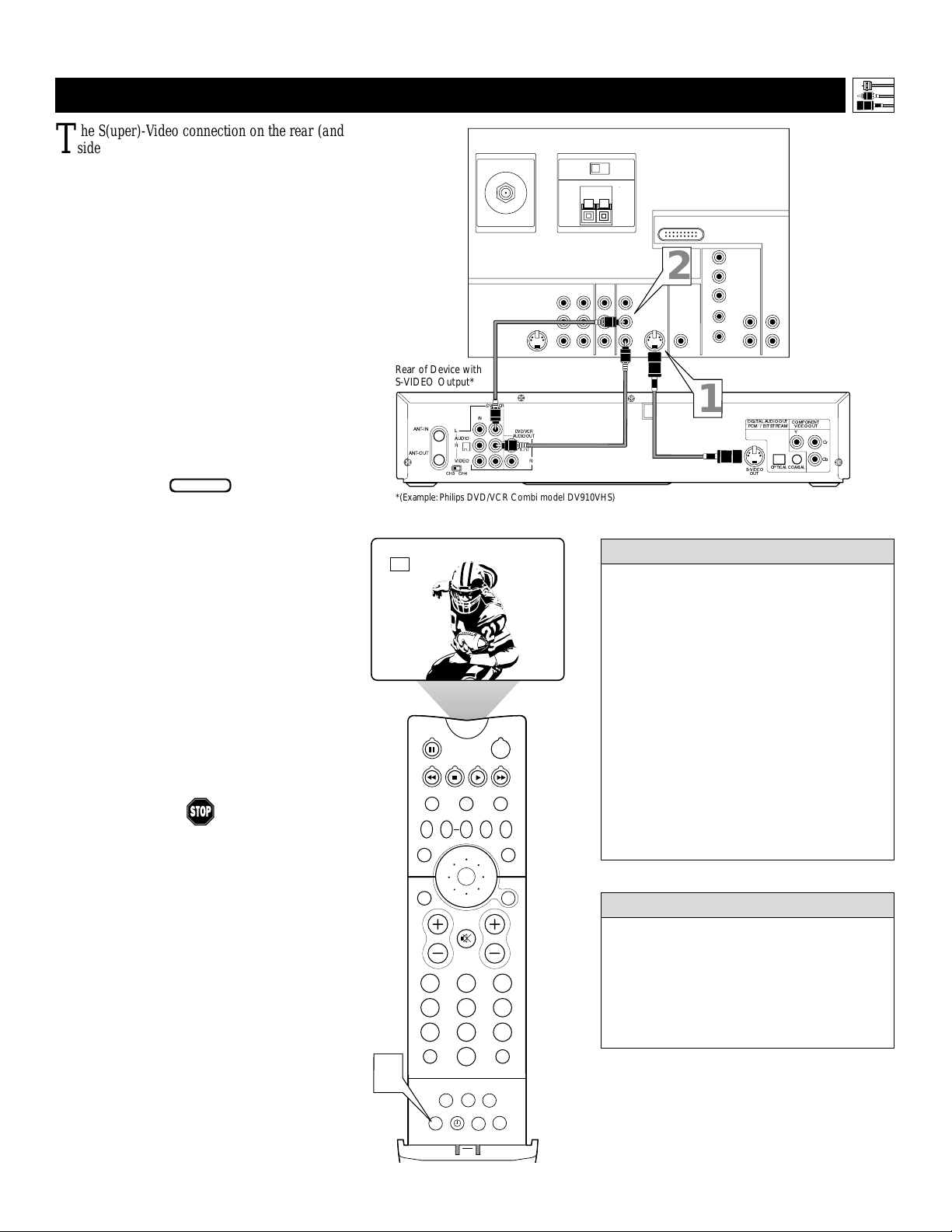
T
he S(uper)-Video connection on the rear (and
side panel) of the TV can give you better picture detail and clarity for the playback of S-VHS
VCR tapes or DVDs than the normal antenna
(RF signal) or Video (composite) picture connections. The example given connects a DVD/VCR
Combi unit to the INPUT-AV 2 jacks on the rear
of the TV.
NOTE: The accessory device must have an
S-VIDEO output jack to make the connection
explained on this page.
To make the connections, you will need:
• one S-Video cable
• two cables for audio connections (standard
RCA connectors).
NOTE: The cables are not supplied with your TV.
You should be able to buy them at most stores
that sell electronics. Or you can call our
Customer Care Center at 1-800-531-0039.
1
Connect the S-VIDEO OUT jack on the
rear of the accessory device with
S-VIDEO output to the INPUT-AV 2
S-VIDEO jack on the rear of the TV.
2
Connect the DVD/VCR AUDIO OUT
jacks on the rear of the accessory device
to the INPUT-AV 2 AUDIO input jacks on
the rear of the TV.
3
Press the AV button on the remote control as many times as necessary to select
the AV2 source on the TV.
4
Turn the accessory device on and press
play to view the video source material
(DVD or videotape, for example) on
the TV.
Connecting Accessory Devices to Your TV
CONNECTING AN S-VIDEO DEVICE
BEGIN
• To simplify making connections, audio
cables are often color coded: red for the
right channel, and white for the left channel. The jacks on your TV are likewise
color coded to match the connectors. To
make S-Video connections, you must use
an S-Video cable.
• You can also connect a satellite receiver,
laser-disc player, video-game player, or
other accessory device with S-Video
capability to the TV in a manner similar
to example shown on this page.
• If you connect a satellite receiver to the
TV, you will need to use the receiver’s
channel-memorization system to store
channels in the receiver’s memory.
HELPFUL HINTS
Video sources that show a constant nonmoving pattern on the TV screen can cause picture-tube damage. When you are not using
your video accessory devices, turn them off.
Also, regularly alternate the use of accessory
video sources with normal TV viewing. See
page 62.
WARNING
13
CENTER CHANNEL AMP INPUT
INPUT-AV 1
VIDEO
L
AUDIO
R
AMP SWITCH
EXT INT
+
Y
Pb
Pr
ANTENNA IN 75Ω
S-VIDEO
L
Rear of Device with
S-VIDEO Output*
DVD/VCR
OUT
AUDIO
R
VIDEO
CH3 CH4
IN
L
DVD/VCR
AUDIO OUT
L
R
ANT-IN
ANT-OUT
*(Example: Philips DVD/VCR Combi model DV910VHS)
Rear of TV
_
HD INPUT-AV 5
DVI
HD INPUT-AV 4
G/Y
1
SYNC
R/Pr
B/Pb
V
H
L
AUDIO
R
DIGITALAUDIO OUT
PCM / BITSTREAM
S-VIDEO
OUT
AUDIO
OPTICAL
L
R
COMPONENT
VIDEO OUT
Y
COAXIAL
Cr
Cb
AUDIO
2
INPUT-AV 2 SUBWOOFEROUTPUT
VIDEO
S-VIDEO
L
L
R
14
T
he following instructions explain how to
connect a DVD player with progressive-scan
capability to the HD INPUT-AV 4 jacks on
your TV.
To make the connections, you will need:
• three cables for video connections (standard
RCA connectors)
• two cables for audio connections (standard
RCA connectors).
NOTE: The cables are not supplied with your TV.
You should be able to buy them at most stores
that sell electronics. Or you can call our
Customer Care Center at 1-800-531-0039.
1
Connect from the YPrPb jacks on
the
rear of the DVD player to the
HD INPUT-
AV 4 G/Y, R/Pr, B/Pb jacks
on the rear of the TV.
2
Connect from the L(eft) and R(ight)
AUDIO OUT jacks on the rear of the
DVD player to the HD INPUT-AV 4
AUDIO L(eft) and R(ight) jacks on the rear
of the TV
.
3
Make sure the DVD player is in progressive-scan mode. You will not get a
viewable picture through the HD
INPUT-AV 4 jacks if the DVD player is
in interlaced mode.
For more information on placing your
DVD player in progressive-scan mode,
see the DVD player’s directions-for-use
manual. Also, see the Helpful Hints to
the right. The way in which progressive-scan mode is selected varies among
DVD players.
4
Press the AV button on your TV remote
control as many times as necessary to
select the
AV4 signal source.
5
Turn the DVD on, insert a disc, and
press play to view a DVD on the TV.
If you experience difficulties receiving
sound with a DVD disc, check the sound
settings through the DVD disc’s menu.
HELPFUL HINT
To prevent uneven picture-tube aging, do not
leave nonmoving images or picture borders on
the screen for an extended period. See page 62.
W
ARNING
CONNECTING A DVD P
LAYER WITH PROGRESSIVE-SCAN CAPABILITY
Connecting Accessory Devices to Your TV
BEGIN
PIP ON/OFF
213
546
879
0
TV
SWAP PIP CH
DN
UP
ACTIVE
CONTROL
FREEZE
SOUND
MUTE
SURF
A/CH
POWER
PICTURE
STATUS/
EXIT
SURF
ITR/
RECORD
HOME
VIDEO
HOME
MOVIES
PERSONAL
SLEEP
REC •
PIPPOSITION
VCR
ACC
MENU/
SELECT
VOL
CH
TV/VCR
FORMAT
SAP
PROG.LISTDOLBY VAV
4
AV4
• If after connecting your DVD player your
display is filled with wavy lines, it may be
that your DVD player is not set to progressive-scan mode. Some DVD players have an
I/P (interlaced/progressive scan) switch
located on the back or front of the players for
changing from interlaced to progressive-scan
mode. Other DVD players may allow the
mode to be changed by pressing a button on
the DVD player’s remote control or by using
the DVD player’s onscreen menu. If the
interlaced/progressive-scan selection
option is provided only through the DVD
onscreen menu, you will need to connect
the DVD player to another AV input
source in addition to HD INPUT-AV 4 to
see the DVD menu. Select this additional
AV source on screen to see the DVD menu
and choose progressive-scan mode. You
will then be able to see the DVD picture
through the AV4 source.
• Some DVD players have dedicated progressive-scan output jacks that are labeled as
such and require no switching to provide a
picture through the HD INPUT-AV 4 jacks.
See your DVD player’s directions-for-use
manual for information.
• The default color-space setting for the
HD INPUT-AV 4 jacks is YPbPr. RGB is
also an option. If the picture’s color looks
grossly incorrect, try changing either the
DVD player’s or TV’s color-space setting.
See the DVD player’s directions-for-use
manual for information on setting its color
space. Or see page 61 in this manual to set
the TV’s color space.
• The Picture-in-Picture (PIP) feature does
not function with AV4 or AV5.
HELPFUL HINTS
CENTER CHANNEL AMP INPUT
INPUT-AV 1
VIDEO
L
AUDIO
R
AMP SWITCH
EXT INT
+
Pb
Pr
Rear of TV
_
HD INPUT-AV 5
DVI
HD INPUT-AV 4
INPUT-AV 2 SUBWOOFEROUTPUT
Y
VIDEO
S-VIDEO
L
L
AUDIO
R
AUDIO OUT
2CH
BITSTREAM
/PCM
L
R
OPTICAL
COAXIAL
DIGITAL
1
G/Y
R/Pr
AUDIO
2
L
R
AC IN ~
B/Pb
V
L
SYNC
AUDIO
H
R
ANTENNA IN 75Ω
S-VIDEO
L
VIDEO OUT
3
Rear of DVD Player with Progressive-scan Capability
Y
VIDEO
B
P
PR
SELECT
I
S
P
15
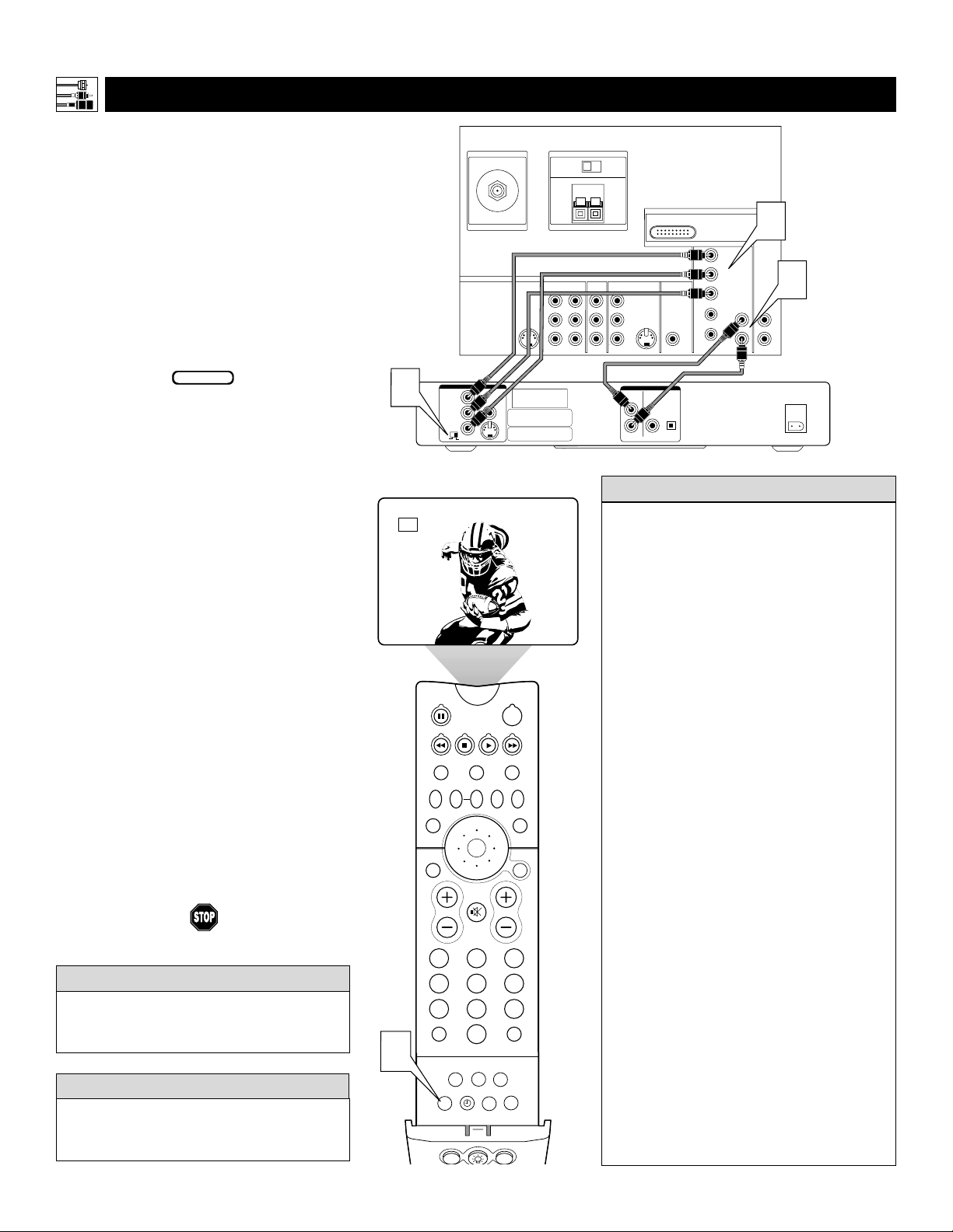
CONNECTING AN HD R
ECEIVER TO THE HD INPUT-AV 4 JACKS
Connecting Accessory Devices to Your TV
• Making a standard connection along with the HD connection as shown
in the example (S-VIDEO) on this page will allow you to see the receiver’s onscreen menu and a picture (valid signal) from the receiver should
it be switched to SD mode.
• The HD INPUT-AV 4 jacks are for standard RCA connectors. Your HD
receiver may use RCA or BNC output jacks. If your HD receiver comes
with BNC jacks, you will need to purchase BNC-to-RCA adapters to
connect the receiver to the TV. You should be able to purchase these
adapters at most stores that sell electronics. Or you can call our
Customer Care Center at 1-800-531-0039.
• The HD INPUT-AV 4 jacks are compatible with some digital equipment
having RGB outputs with “sync on green” or RGB with “separate H and V
sync.” Output standards for digital equipment, however, may vary by manufacturer. No industry standards have been established for HD television RGB
signal systems, timing, synchronization, and signal strengths. If the digital
equipment you want to connect to your TV offers both component video and
RGB outputs, component video is the suggested connection to use.
• The default color-space setting for the HD INPUT-AV 4 jacks is YPbPr.
RGB is also an option. If the picture color looks grossly incorrect, try
changing either the receiver’s or TV’s color space. See the receiver’s
directions-for-use manual for information on setting its color space. Or
see page 61 in this manual for setting the TV’s AV4 color space.
• AV4 and AV5 do not function with the PIP feature. They cannot be displayed in the PIP window, nor can the PIP window be displayed when
those signal sources are being viewed on the main screen.
HELPFUL HINTS
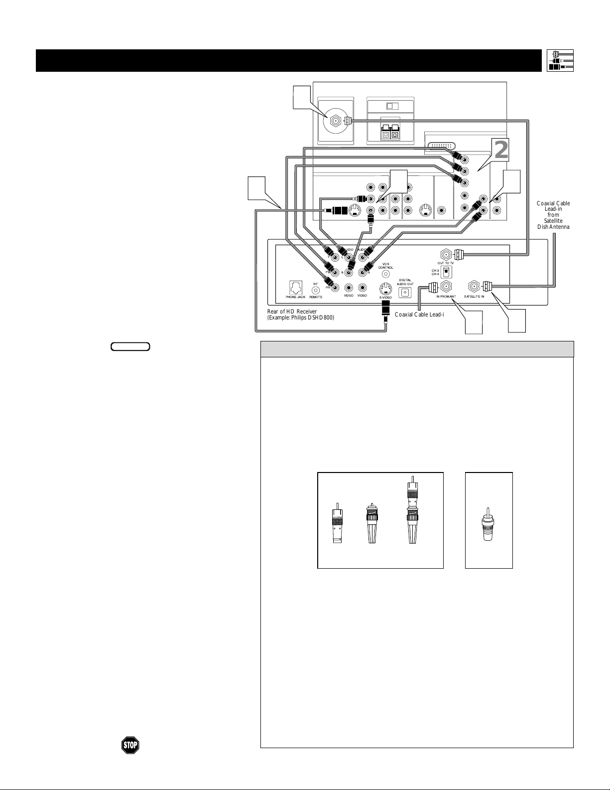
BNC-to-
RCA
Adapter
BNC
Connector
Adapter
Fitted to
Connection
OR
RCA
Connector
D
igital equipment with a 1080i or 480p output, is compatible with the HD INPUT-AV 4
video jacks.
NOTE: This television is designed to be compati-
ble with high-definition signal standards 1080i
and 480p as specified by the Electronic Industries
Association standard EIA770.3. Because output
standards may vary by manufacturer, you may
encounter some digital equipment that will not
properly display pictures on the TV.
To make the connections shown in this example,
you will need:
• one S-VIDEO cable
• three cables for video connections (standard
RCA connectors)
• four cables for audio connections (standard
RCA connectors)
• one coaxial cable (75Ω).
NOTE: The cables are not supplied with your TV.
You should be able to buy them at most stores
that sell electronics. Or you can call our
Customer Care Center at 1-800-531-0039.
1
Connect S-VIDEO and audio cables.
NOTE: This example uses
INPUT-AV 1. You can use INPUT-AV 2 or
the side input jacks if you want.
• Connect an S-VIDEO cable from the HD
receiver’s S-VIDEO jack to the TV’s
INPUT-AV 1 S-VIDEO jack.
• Connect from the HD receiver’s AUDIO
L(eft) and R(ight) jacks to the TV’s
INPUT-AV 1 L(eft) and R(ight) AUDIO
jacks.
2
Connect component video and audio
cables to the TV’s HD inputs.
• Connect from the YPRPB jacks on
the HD receiver to the TV’s HD
INPUT-AV 4 G/Y, R/Pr, B/Pb jacks.
• Connect from the HD receiver’s AUDIO
L(eft) and R(ight) jacks to the TV’s HD
INPUT-AV 4 L(eft) and R(ight) AUDIO
jacks.
3
Connect coaxial cables.
• Connect the coaxial cable lead-in from
your cable outlet, cable converter box, or
VHF/UHF antenna to the IN FROM
ANT jack on the HD receiver.
• Connect a coaxial cable from the OUT
TO TV jack to the ANTENNA IN 75Ω
jack on the TV.
• Connect the coaxial cable lead-in from a
satellite dish antenna to the SATELLITE
IN jack on the HD receiver.
4
Refer to the directions-for-use manual
that came with the HD receiver for setup
instructions.
BEGIN
1
Rear of HD Receiver
(Example: Philips DSHD800)
3
ANTENNA IN 75Ω
AUDIO
Y
L
PB
RF
PR
REMOTEPHONE JACK
S-VIDEO
L
VIDEO
AUDIO
AUDIO
VIDEOVIDEO
AMP SWITCH
EXT INT
+
CENTER CHANNEL AMP INPUT
INPUT-AV 1
L
R
L
VCR
CONTROL
RR
S-VIDEO
_
INPUT-AV 2 SUBWOOFEROUTPUT
Y
VIDEO
1
Pb
L
AUDIO
Pr
R
DIGITAL
AUDIO OUT
Coaxial Cable Lead-in
from Cable Outlet,
Cable Converter Box,
or VHF/UHF Antenna
DVI
S-VIDEO
L
OUT TO TV
CH 3
CH 4
IN FROM ANT SATELLITEIN
Rear of TV
HD INPUT-AV 5
HD INPUT-AV 4
G/Y
R/Pr
B/Pb
V
L
SYNC
AUDIO
H
R
3
2
AUDIO
L
R
2
3
Coaxial Cable
Lead-in
from
Satellite
Dish Antenna
16
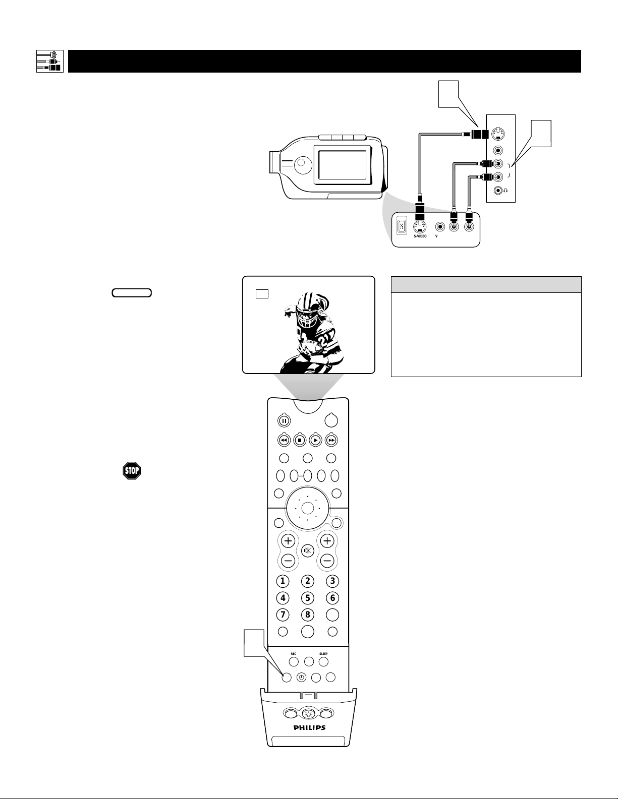
CONNECTING A C
AMCORDER
T
he side panel jacks provide a convenient way
for you to connect a camcorder to your TV.
The side panel jacks are recognized by your TV
as AV3.
You can obtain S-VIDEO quality with an S-VHS,
Hi-8, or digital camcorder by connecting to the
S-VIDEO input instead of the VIDEO (composite)
input.
To make the connections shown in this example,
you will need:
• an S-VIDEO cable
• two cables for audio connections (standard
RCA connectors).
NOTE: The cables are not supplied with your TV.
You should be able to buy them at most stores
that sell electronics. Or you can call our
Customer Care Center at 1-800-531-0039.
1
Connect from the S-VIDEO output on
the camcorder to the S-VIDEO input in
the TV’s side panel.
2
Connect from the AUDIO outputs on
the camcorder to the side panel AUDIO
L(eft) and R(ight) inputs.
3
Press the AV button on the remote control as many times as necessary to select
the AV3 source on the TV.
4
Turn the camcorder on, insert a videotape and press PLAYto view the tape
on the TV.
Connecting Accessory Devices to Your TV
BEGIN
PIP ON/OFF
213
546
879
0
TV
SWAP PIP CH
DN
UP
ACTIVE
CONTROL
FREEZE
SOUND
MUTE
SURF
A/CH
POWER
PICTURE
STATUS/
EXIT
SURF
ITR/
RECORD
HOME
VIDEO
HOME
MOVIES
PERSONAL
SLEEP
REC •
PIPPOSITION
VCR
ACC
MENU/
SELECT
VOL
CH
TV/VCR
FORMAT
SAP
PROG.LISTDOLBY VAV
3
AV3
To simplify making connections, the connectors on audio cables are often color
coded: red for the right channel, and white
for the left channel. The jacks on your TV
are likewise color coded to match the connectors. To make S-Video connections, you
must use an S-Video cable.
HELPFUL HINT
Typical
Camcorder
S-VIDEO
DV
1
VIDEO AUDIO
Side Jack Panel
LEFT RIGHT
S-VIDEO
VIDEO
L
AUDIO
R
G
2
17
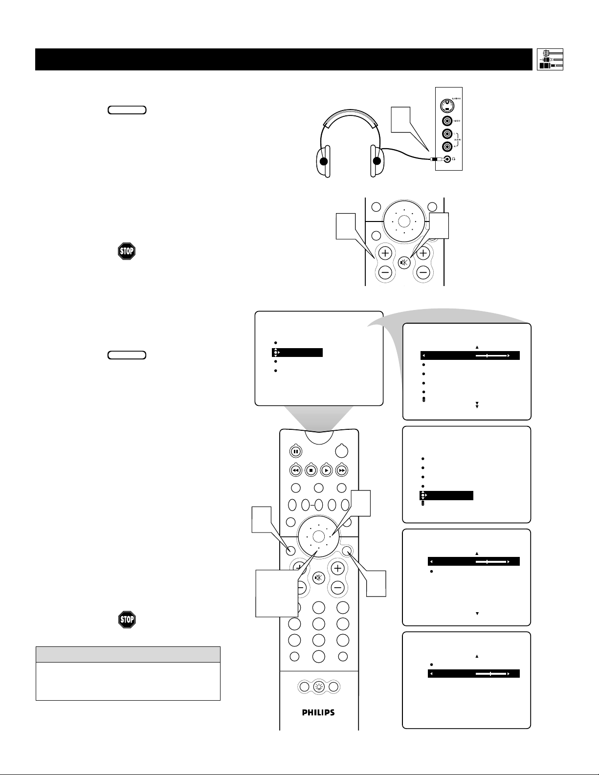
CONNECTING AND U
SING HEADPHONES WITH YOUR TV
T
he HEADPHONE controls allow you to
adjust the volume and balance of the
sound going to the headphones.
1
Press the MENU/SELECT button
on the remote control to show the
onscreen menu.
2
Press the CURSOR RING DOWN
once to highlight SOUND.
3
Press the CURSOR RING RIGHT
to enter the SOUND submenu.
4
Press the CURSOR RING DOWN
repeatedly until HEADPHONE is
highlighted. Then press the CURSOR
RING RIGHT to enter the
HEADPHONE submenu.
5
Press the CURSOR RING DOWN
or UP to highlight VOLUME or
BALANCE. Then press the CURSOR
RING LEFT or RIGHT to adjust the
control.
6
Press the STATUS/EXIT button to
exit the menu.
T
he TV’s side panel has a headphone jack for
personal listening.
1
Insert the headphone plug into the headphone jack ; in the TV’s side panel.
2
Turn down the TV’s volume or press
the Mute button
cc
on the remote con-
trol to turn off the TV’s internal speakers.
See the section below for information on
adjusting headphone volume and balance.
NOTE: The headphone impedance must
be between 8 and 4,000 ohms. The headphone jack is stereo and 3.5 mm in size.
Connecting Accessory Devices to Your TV
The AVL, INCR. SURROUND, and BASS
BOOST controls do not function with the
headphones.
HELPFUL HINT
BEGIN
BEGIN
Side Jack Panel
G
1
PICTURE
MENU/
SELECT
2
MUTE
CH
SOUND
TREBLE 30
BASS
BALANCE
AVL
INCR . SURROUND
PICTURE
SOUND
FEATURES
INSTALL
2
TREBLE
BASS
BALANCE
AVL
INCR . SURROUND
STATUS/
EXIT
VOL
SOUND
6
STATUS/
2, 4,
5
TV
SWAP PIP CH
SOUND
EXIT
VOL
TV/VCR
A/CH
POWER
ACC
VCR
ACTIVE
FREEZE
CONTROL
DN
UP
PICTURE
MENU/
SELECT
MUTE
213
546
879
SURF
0
POSITION
PIP
CH
3
1
SOUND
TREBLE
BASS
BALANCE
INCR . SURROUND
HEADPHONE
SOUND
HEADPHONE
VOLUME 30
BALANCE
SOUND
HEADPHONE
VOLUME
BALANCE 0
VOLUME
BALANCE
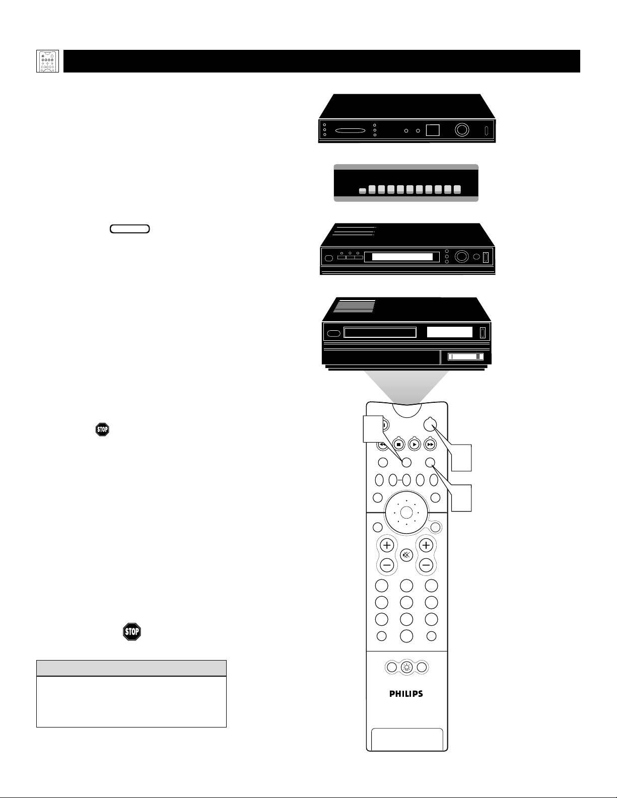
18
PROGRAMMING THE
TV REMOTE TO WORK WITH ACCESSORY DEVICES
Y
our TV remote is capable of working not
only your TV but also other infrared
remote (IR) controlled devices such as VCRs,
cable TV converter boxes, satellite receivers,
DVD players, and laser-disc players.
If you want to use your TV remote to operate a VCR or other accessory device, you
will need to perform this initial check
explained in this section. You may also need
to go to the sections on the “Code-entry
Method” and the “Search Method” in the
pages that follow.
1
Press the VCR orACC(essory)
mode button on the TV remote for
the desired accessory device category.
NOTE: Pressing the VCR mode button
allows access to product codes for
VCRs. Pressing the ACC(essory) mode
button allows access to the product
codes for cable TV converters, satellite
receivers, DVD players, and laser-disc
players.
2
Point the TV remote toward the
desired accessory device and press
the POWER button.
Does the remote turn the accessory
device on?
If yes, and try other function but-
tons on the TV remote. With a VCR,
for example, try the Play, Stop, and
Rewind buttons, for example. (See
page 23 for information on how the
remote buttons correspond with accessory device functions.) If they also
work the accessory device, then the
remote is ready and no further steps
are needed.
If not, do the following:
Look up a four-digit remote code
number on pages 21 or 22 for your
brand of accessory device. Then go
through the simple steps for entering a
four-digit code as explained on
page 19.
BEGIN
Using the Remote Control
If more than one four-digit code number is
listed, you may have to try more than the
first number given to locate your device’s
correct code.
HELPFUL HINT
POWER
ACC
TV
VCR
ACTIVE
SWAP PIP CH
FREEZE
CONTROL
DN
UP
PICTURE
SOUND
Satellite Receiver
Cable Converter Box
DVD Player
VCR
1
TV
VCR
SWAP PIP CH
SOUND
STATUS/
EXIT
VOL
TV/VCR
A/CH
ACTIVE
CONTROL
DN
UP
MUTE
213
546
879
0
POWER
ACC
FREEZE
PICTURE
SURF
MENU/
SELECT
2
1
CH
POSITION
PIP
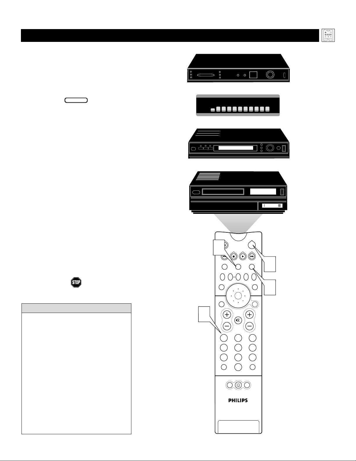
19
USING THE CODE-ENTRY METHOD TO PROGRAM YOUR TV REMOTE
N
ow that you have looked up the four-
digit remote-control Direct-entry Code
for your brand of accessory device, you are
ready to follow the simple steps shown below
to program your TV remote.
Please read through all the steps before
beginning.
1
First, press and hold down the VCR
or ACC (for an accessory device
other than a VCR) mode button on
the TV remote. Then press and hold
down the MENU/SELECT button at
the same time for a brief moment.
Release the buttons. The TV remote
back light will switch on.
NOTE: For correct operation, you
must first press and hold the mode
button and then press and hold the
MENU/SELECT button simultaneously.
2
Within 30 seconds of pressing the
VCR (or ACC) button and
MENU/SELECT button, enter a
four-digit code for the accessory
device (see pages 21 and 22).
If you make a mistake while attempting to enter the four-digit code and
want to start again, press any button
other than one with a number. Then
return to step 1 to begin again.
3
Point the remote at the accessory
device. Then press the POWER button
on the remote to turn the device on.
BEGIN
Using the Remote Control
• If you do not enter a complete code within
30 seconds, you will need to perform step
1 of the Code-entry Method again.
• If you enter more than four digits, the unit
will retain the first four digits entered.
• If the procedure explained above does not
work the first time, repeat the steps using
the same remote code number.
• If after a second try the remote does not
operate your accessory device, and more
code numbers are listed for your brand,
use the next listed code number.
• If after repeated attempts the Entry-code
Method does not allow you to work your
accessory device with your TV remote, try
the Search Method explained on the next
page.
HELPFUL HINTS
POWER
ACC
TV
VCR
ACTIVE
SWAP PIP CH
FREEZE
CONTROL
DN
UP
PICTURE
SOUND
Satellite Receiver
Cable Converter Box
DVD Player
VCR
1
TV
VCR
SWAP PIP CH
SOUND
STATUS/
EXIT
ACTIVE
CONTROL
DN
UP
POWER
ACC
FREEZE
PICTURE
MENU/
SELECT
3
1
2
VOL
MUTE
213
546
879
TV/VCR
A/CH
0
POSITION
CH
SURF
PIP

20
USING THE S
EARCH METHOD TO PROGRAM YOUR TV REMOTE
Y
our TV remote can be set to work various
accessory devices (VCRs, cable converters, and satellite receivers, for example) by
what is called the Search Method.
NOTE: The Search Method works only with
devices equipped with channel-display indicators on the devices themselves or the ability to show channel numbers on the TV
screen. If the Code-entry Method (shown in
the previous section) did not enable your TV
remote to work your accessory device, then
follow the easy steps listed below. Please
read the steps once before performing them.
1
Turn on the desired device. Press
and hold down the VCR orACC
(for an accessory device other than
a VCR) mode button on the TV
remote. Then press and hold down the
SURF button as you hold down the
desired mode (VCR or ACC) button.
NOTE: For correct operation, you
must press and hold down the desired
mode (VCR or ACC) button first and
then press and hold down the SURF
button second.
While holding down the SURF and
the desired mode (VCR orACC)
buttons simultaneously, point the
remote toward the accessory device
and continue holding the buttons
down.
2
Watch the Channel Indicator on
your accessory device. Channel num-
bers will scan up when the TV remote
has identified the correct code for
your accessory device. This may take
several minutes.
3
Release the mode (VCR or ACC)
and SURF buttons as soon as channel numbers start to scan up. The
scanning means that your TV remote
has found the code for your accessory
device.
NOTE:
If no channel change happens
after several minutes, repeat steps 1 and
2. Then if a channel change still does not
occur, the remote will not work with the
desired accessory device.
BEGIN
Using the Remote Control
• The remote’s back light will blink
as the remote moves through its
product code list. After the remote
identifies the product code for
your accessory device and you
release the remote buttons, the
back light will blink twice.
• Your TV remote may locate the
accessory device’s code quickly or
within several minutes.
• Don’t let the accessory device
scan up more than five channels
when the correct code is found—
the remote may pass up the right
code and have to repeat the search
cycle.
HELPFUL HINTS
POWER
ACC
TV
VCR
ACTIVE
SWAP PIP CH
FREEZE
CONTROL
DN
UP
PICTURE
SOUND
Satellite Receiver
Cable Converter Box
06
07
08
1,3
TV
SWAP PIP CH
SOUND
STATUS/
EXIT
VOL
TV/VCR
A/CH
06
09
VCR
06
POWER
ACC
VCR
ACTIVE
FREEZE
CONTROL
DN
UP
PICTURE
MENU/
SELECT
MUTE
213
546
879
SURF
0
POSITION
PIP
07
07
CH
08
09
08
09
1,3
1,3

21
DIRECT-ENTRY
CODES FOR A/V ACCESSORY DEVICES
S
EE THE NEXT PAGE FOR MORE CODES.
Using the Remote Control
VCR
CODE NUMBER
DENON . . . . . . . . . . . . . . . .0859
GE . . . . . . . . . . . . . . . . . . .0862
H
ARMAN/KARDON . . . . . . . .0871
H
ITACHI . . . . . . . . . . . . . . . .0870
JVC . . . . . . . . . . . . . . . . . .0868
KENWOOD . . . . . . . . . . . . .0865
MAGNAVOX . . . . . . . . . . . . .0860
MARANTZ . . . . . . . . . . . . . .0866
MITSUBISHI . . . . . . . . . . . . . .0861
ONKYO . . . . . . . . . . . . . . . .0860
O
PTIMUS . . . . . . . . . . . . . . .0869
P
ANASONIC . . . . . . . . . . . . .0859
PHILIPS . . . . . . . . . . . . . . . . .0866, 0860
PIONEER . . . . . . . . . . . . . . .0869, 0863
PROSCAN . . . . . . . . . . . . . . .0862
RCA . . . . . . . . . . . . . . . . . .0862, 0869
SAMSUNG . . . . . . . . . . . . . . .0870
SONY . . . . . . . . . . . . . . . . .0864
T
ECHNICS . . . . . . . . . . . . . .0859
T
HETA DIGITAL . . . . . . . . . . .0869
TOSHIBA . . . . . . . . . . . . . . .0860
YAMAHA . . . . . . . . . . . . . . .0859, 0867
ZENITH . . . . . . . . . . . . . . . .0872, 0860
DVD PLAYER
CODE NUMBER
ADMIRAL . . . . . . . . . . . . . . .0075, 0236
ADVENTURA . . . . . . . . . . . . .0027
AIKO . . . . . . . . . . . . . . . . . .0305
AIWA . . . . . . . . . . . . . . . . .0334,0495,0027, 0064
AKAI . . . . . . . . . . . . . . . . . .0133,0080, 0068, 0076,
. . . . . . . . . . . . . . . . . . . . .0088,0183,0269
AMERICA A
CTION . . . . . . . . .0305
A
MERICAN HIGH . . . . . . . . . .0062
ASHA . . . . . . . . . . . . . . . . .0267
AUDIOVOX
. . . . . . . . . . . . . .0064
B
EAUMARK . . . . . . . . . . . . . .0267
BELL & HOWELL . . . . . . . . . .0131
BROKSONIC . . . . . . . . . . . . .0148, 0211,0029,0236,
. . . . . . . . . . . . . . . . . . . . .0238,0322,0388,0506
CCE . . . . . . . . . . . . . . . . . .0099, 0305
CALIX . . . . . . . . . . . . . . . . .0064
CANON . . . . . . . . . . . . . . . .0194,0062,0129
CAPEHART . . . . . . . . . . . . . .0047
CARVER . . . . . . . . . . . . . . . .0108
CINERAL . . . . . . . . . . . . . . .0305
CITIZEN . . . . . . . . . . . . . . . .0305, 0064
COLT . . . . . . . . . . . . . . . . .0099
CRAIG . . . . . . . . . . . . . . . . .0064, 0099, 0074, 0267,
. . . . . . . . . . . . . . . . . . . . .0298
CURTIS MATHES . . . . . . . . . .0062,0068,0087, 0189
CYBERNEX . . . . . . . . . . . . . .0078,0267
DAEWOO . . . . . . . . . . . . . . .0305,0588,0047, 0072
DAYTRON . . . . . . . . . . . . . .0047
DENON . . . . . . . . . . . . . . . .0069
DYNATECH . . . . . . . . . . . . . .0027
ELECTROHOME . . . . . . . . . . .0064
ELECTROPHONIC . . . . . . . . . .0064
EMEREX . . . . . . . . . . . . . . . .0059
EMERSON . . . . . . . . . . . . . . .0211, 0029, 0236,0305,
. . . . . . . . . . . . . . . . . . . . .0063,0148,0238,0588,
. . . . . . . . . . . . . . . . . . . . .0235,0321,0506,0088,
. . . . . . . . . . . . . . . . . . . . .0115,0239,0027,0064,
. . . . . . . . . . . . . . . . . . . . .0070,0095,0322,0388,
. . . . . . . . . . . . . . . . . . . . .0537
FISHER . . . . . . . . . . . . . . . . .0074,0131, 0081, 0093
FUJI . . . . . . . . . . . . . . . . . . .0060, 0062
FUNAI . . . . . . . . . . . . . . . . .0027
GE . . . . . . . . . . . . . . . . . . .0062, 0087,0075,0092,
. . . . . . . . . . . . . . . . . . . . .0229,0267
GARRARD . . . . . . . . . . . . . .0027
GO VIDEO . . . . . . . . . . . . . .0306,0459, 0553, 0259
GOLDSTAR . . . . . . . . . . . . . .0064,0045,0065, 0498,
. . . . . . . . . . . . . . . . . . . . .0507
GRADIENTE . . . . . . . . . . . . .0035,0027,0435
GRUNDIG . . . . . . . . . . . . . . .0222
HI-Q . . . . . . . . . . . . . . . . .0074
H
ARLEY DAVIDSON . . . . . . . .0027
H
ARMAN/KARDON . . . . . . . .0065, 0102, 0108
H
ARWOOD . . . . . . . . . . . . .0095, 0099
HEADQUARTER . . . . . . . . . . .0073
H
ITACHI . . . . . . . . . . . . . . . .0069, 0193, 0132,0092,
. . . . . . . . . . . . . . . . . . . . .0027,0068,0109
H
UGHES NETWORK SYSTEMS .0069
JVC . . . . . . . . . . . . . . . . . .0094, 0035,0233,0234,
. . . . . . . . . . . . . . . . . . . . .0068,0411
JENSEN . . . . . . . . . . . . . . . . .0068
KEC . . . . . . . . . . . . . . . . . .0064,0305
KLH . . . . . . . . . . . . . . . . . .0099
KENWOOD . . . . . . . . . . . . .0068, 0094,0411,0065
KODAK . . . . . . . . . . . . . . . .0062, 0064
LXI . . . . . . . . . . . . . . . . . . .0064
LLOYD'S . . . . . . . . . . . . . . . .0027, 0235
LOGIK . . . . . . . . . . . . . . . . .0099
MEI . . . . . . . . . . . . . . . . . .0062
MGA . . . . . . . . . . . . . . . . .0070, 0088,0267
MGN TECHNOLOGY . . . . . . .0267
MTC . . . . . . . . . . . . . . . . .0027, 0267
MAGNASONIC . . . . . . . . . . . .0305
MAGNAVOX
. . . . . . . . . . . . .0062,0108,0137,0130,
. . . . . . . . . . . . . . . . . . . . .0027,0066,0176
M
AGNIN . . . . . . . . . . . . . . .0267
MARANTZ . . . . . . . . . . . . . .0108, 0062
MARTA . . . . . . . . . . . . . . . . .0064
MATSUSHITA . . . . . . . . . . . . .0062, 0189,0481
MEMOREX . . . . . . . . . . . . . .0131, 0074, 0506, 0027,
. . . . . . . . . . . . . . . . . . . . .0064,0075,0062,0073,
. . . . . . . . . . . . . . . . . . . . .0267,0334,0066,0189,
. . . . . . . . . . . . . . . . . . . . .0236,0481,0828,0829
MINOLTA
. . . . . . . . . . . . . . .0132,0069
M
ITSUBISHI . . . . . . . . . . . . . .0200, 0088, 0102, 0241,
. . . . . . . . . . . . . . . . . . . . .0269,0070,0075,0094,
. . . . . . . . . . . . . . . . . . . . .0470
MOTOROLA . . . . . . . . . . . . .0062, 0075
MULTITECH . . . . . . . . . . . . .0027,0099
NAD . . . . . . . . . . . . . . . . .0085
NEC . . . . . . . . . . . . . . . . . .0065, 0067, 0068,0077,
. . . . . . . . . . . . . . . . . . . . .0094,0109,0131
NIKKO . . . . . . . . . . . . . . . . .0064
NIKON . . . . . . . . . . . . . . . .0061, 0280
NOBLEX . . . . . . . . . . . . . . .0267
OLYMPUS . . . . . . . . . . . . . . .0062, 0253
OPTIMUS . . . . . . . . . . . . . . .0189, 0481, 0827, 0828,
. . . . . . . . . . . . . . . . . . . . .0075,0085,0829,0064,
. . . . . . . . . . . . . . . . . . . . .0131,0459
OPTONICA . . . . . . . . . . . . . .0089
ORION . . . . . . . . . . . . . . . .0506, 0029, 0211, 0236,
. . . . . . . . . . . . . . . . . . . . .0322
PANASONIC . . . . . . . . . . . . .0062, 0189, 0828,0481,
. . . . . . . . . . . . . . . . . . . . .0253,0104,0405,0829,
. . . . . . . . . . . . . . . . . . . . .0129,0252,0254,0273,
. . . . . . . . . . . . . . . . . . . . .0827
PENNEY . . . . . . . . . . . . . . . .0062,0267,0064, 0069,
. . . . . . . . . . . . . . . . . . . . .0065,0067,0081
PENTAX . . . . . . . . . . . . . . . .0069, 0092, 0132
PHILCO . . . . . . . . . . . . . . . .0062,0236,0506
PHILIPS . . . . . . . . . . . . . . . . .0108, 0062,0089,0137,
. . . . . . . . . . . . . . . . . . . . .0830,0831
P
ILOT . . . . . . . . . . . . . . . . .0064
P
IONEER . . . . . . . . . . . . . . .0085, 0195, 0094
P
OLK AUDIO . . . . . . . . . . . .0108
PORTLAND . . . . . . . . . . . . . .0047
P
ROFITRONIC . . . . . . . . . . . .0267
P
ROSCAN . . . . . . . . . . . . . . .0087, 0229
PROTEC . . . . . . . . . . . . . . . .0099
P
ULSAR . . . . . . . . . . . . . . . .0066, 0078
Q
UARTER . . . . . . . . . . . . . . .0073
QUARTZ . . . . . . . . . . . . . . .0073
QUASAR . . . . . . . . . . . . . . .0062,0189,0104,0481,
. . . . . . . . . . . . . . . . . . . . .0828
RCA . . . . . . . . . . . . . . . . . .0087, 0176, 0229,0069,
. . . . . . . . . . . . . . . . . . . . .0132,0085,0062,0075,
. . . . . . . . . . . . . . . . . . . . .0092,0104,0133,0267,
. . . . . . . . . . . . . . . . . . . . .0304
RADIO SHACK
. . . . . . . . . . .0027
R
ADIX . . . . . . . . . . . . . . . . .0064
RANDEX . . . . . . . . . . . . . . .0064
REALISTIC . . . . . . . . . . . . . . .0027, 0131, 0074,0075,
. . . . . . . . . . . . . . . . . . . . .0064,0062,0089,0073,
. . . . . . . . . . . . . . . . . . . . .0093
RICOH . . . . . . . . . . . . . . . . .0061, 0280
RUNCO . . . . . . . . . . . . . . . .0066
STS . . . . . . . . . . . . . . . . . .0069
SALORA . . . . . . . . . . . . . . . .0102
SAMSUNG . . . . . . . . . . . . . . .0072, 0078, 0080,0267
SANKY . . . . . . . . . . . . . . . . .0066, 0075
SANSUI . . . . . . . . . . . . . . . .0068, 0506,0027,0094,
. . . . . . . . . . . . . . . . . . . . .0109,0236,0298
SANYO . . . . . . . . . . . . . . . . .0074,0073, 0131, 0267
SCOTT . . . . . . . . . . . . . . . . .0211, 0238, 0148,0070,
. . . . . . . . . . . . . . . . . . . . .0072,0237,0239
SEARS . . . . . . . . . . . . . . . . .0081,0132,0064, 0069,
. . . . . . . . . . . . . . . . . . . . .0027,0062,0073,0074,
. . . . . . . . . . . . . . . . . . . . .0093,0131
SEMP . . . . . . . . . . . . . . . . . .0072
SHARP . . . . . . . . . . . . . . . . .0075,0089
SHINTOM . . . . . . . . . . . . . . .0099
SHOGUN . . . . . . . . . . . . . . .0078, 0267
SINGER . . . . . . . . . . . . . . . .0099
SONY . . . . . . . . . . . . . . . . .0060,0061,0059, 0280,
. . . . . . . . . . . . . . . . . . . . .0027,0038,0062
SUNPAK . . . . . . . . . . . . . . . .0280
SYLVANIA . . . . . . . . . . . . . . .0062,0108,0027, 0070,
. . . . . . . . . . . . . . . . . . . . .0130,0137
SYMPHONIC . . . . . . . . . . . . .0027
TMK . . . . . . . . . . . . . . . . .0063, 0235, 0267
TATUNG . . . . . . . . . . . . . . . .0068
TEAC . . . . . . . . . . . . . . . . . .0027, 0068
TECHNICS . . . . . . . . . . . . . .0062,0189,0273
TEKNIKA . . . . . . . . . . . . . . .0027, 0062,0064,0079
THOMAS . . . . . . . . . . . . . . .0027
TOSHIBA . . . . . . . . . . . . . . .0072, 0237, 0239,0070,
. . . . . . . . . . . . . . . . . . . . .0093,0393
TOTEVISION . . . . . . . . . . . . .0064,0267
UNITECH . . . . . . . . . . . . . . .0267
VECTOR . . . . . . . . . . . . . . . .0072
VECTOR RESEARCH . . . . . . . .0065, 0067
VIDEO CONCEPTS . . . . . . . . .0067,0072, 0088, 0248
VIDEOSONIC . . . . . . . . . . . . .0267
W
ARDS . . . . . . . . . . . . . . . .0062, 0087,0089,0027,
. . . . . . . . . . . . . . . . . . . . .0074,0239,0267,0069,
. . . . . . . . . . . . . . . . . . . . .0075,0099,0108,0176
W
HITE WESTINGHOUSE . . . . .0099, 0305, 0236
XR-1000 . . . . . . . . . . . . . .0099, 0027, 0062
YAMAHA . . . . . . . . . . . . . . .0065
ZENITH . . . . . . . . . . . . . . . .0066, 0027, 0060,0061,
. . . . . . . . . . . . . . . . . . . . .0236,0506
TV
VCR
ACTIVE
SWAP PIP CH
CONTROL
DN
UP
SOUND
POWER
ACC
FREEZE
PICTURE

LASER-DISC PLAYER
22
DIRECT-ENTRY
CODES FOR A/V ACCESSORY DEVICES
Using the Remote Control
CABLE CONVERTER BOX
SATELLITE RECEIVER/DIGITAL SATELLITE SYSTEM
CODE NUMBER
ABC . . . . . . . . . . . . . . . . . .0030, 0028, 0034,0035,
. . . . . . . . . . . . . . . . . . . . .0038,0040,0041,0044,
. . . . . . . . . . . . . . . . . . . . .0060
ALLEGRO . . . . . . . . . . . . . . .0180,0342
ANTRONIX . . . . . . . . . . . . . .0049, 0234
APACHE . . . . . . . . . . . . . . . .0797
ARCHER . . . . . . . . . . . . . . . .0049, 0066, 0180,0234,
. . . . . . . . . . . . . . . . . . . . .0824
BBT . . . . . . . . . . . . . . . . . .0294
BELCOR . . . . . . . . . . . . . . . .0083
BELL & HOWELL . . . . . . . . . .0041
CABLE STAR . . . . . . . . . . . . .0083
CABLETENNA . . . . . . . . . . . .0049
CABLEVIEW . . . . . . . . . . . . .0049
CENTURY
. . . . . . . . . . . . . . .0180
C
ITIZEN . . . . . . . . . . . . . . . .0180, 0342
COLOUR VOICE . . . . . . . . . .0052, 0058
COMBAND
. . . . . . . . . . . . . .0259
C
OMTRONICS . . . . . . . . . . . .0067, 0087
CONTEC . . . . . . . . . . . . . . .0046
DIGI
. . . . . . . . . . . . . . . . . .0664
E
ASTERN . . . . . . . . . . . . . . .0029
EMERSON . . . . . . . . . . . . . . .0824
EVERQUEST . . . . . . . . . . . . . .0042, 0067
FOCUS . . . . . . . . . . . . . . . . .0427
GC ELECTRONICS . . . . . . . . .0083, 0234
GE . . . . . . . . . . . . . . . . . . .0259
GARRARD . . . . . . . . . . . . . .0180
GEMINI . . . . . . . . . . . . . . . .0042,0097,0269, 0824
GENERAL INSTRUMENT . . . . . .0303,0038,0503,0837
GOLDSTAR . . . . . . . . . . . . . .0067,0171
GOODMIND . . . . . . . . . . . . .0797,0824
HAMLIN . . . . . . . . . . . . . . . .0047, 0036, 0286,0061,
. . . . . . . . . . . . . . . . . . . . .0300
HITACHI
. . . . . . . . . . . . . . . .0038
H
YTEX . . . . . . . . . . . . . . . . .0034
JASCO . . . . . . . . . . . . . . . . .0042, 0180, 0342
JERROLD . . . . . . . . . . . . . . . .0030, 0039,0303,0041,
. . . . . . . . . . . . . . . . . . . . .0503,0038,0051,0042,
. . . . . . . . . . . . . . . . . . . . .0837
LINSAY . . . . . . . . . . . . . . . . .0467
MACOM . . . . . . . . . . . . . . . .0060
MAGNAVOX . . . . . . . . . . . . .0054
MEMOREX . . . . . . . . . . . . . .0027
MOVIE TIME . . . . . . . . . . . . .0090, 0183
NSC . . . . . . . . . . . . . . . . . .0183, 0090, 0097
NEXUS . . . . . . . . . . . . . . . .0797
NOVAPLEX
. . . . . . . . . . . . . .0645
O
AK . . . . . . . . . . . . . . . . . .0046, 0034
OPTIMUS . . . . . . . . . . . . . . .0048
PANASONIC
. . . . . . . . . . . . .0048,0134,0027
P
ANTHER . . . . . . . . . . . . . . .0664
PARAGON . . . . . . . . . . . . . .0027
PHILIPS
. . . . . . . . . . . . . . . . .0052,0058,0269,0317,
. . . . . . . . . . . . . . . . . . . . .0054,0180
P
IONEER . . . . . . . . . . . . . . .0171, 0050, 0560
POPULAR MECHANICS . . . . . .0427
PRELUDE . . . . . . . . . . . . . . .0797
PULSAR . . . . . . . . . . . . . . . .0027
QUASAR . . . . . . . . . . . . . . .0027
RCA . . . . . . . . . . . . . . . . . .0048
RADIO SHACK . . . . . . . . . . .0042, 0847,0342,0824
REALISTIC . . . . . . . . . . . . . . .0234
RECOTON . . . . . . . . . . . . . .0427
REGAL . . . . . . . . . . . . . . . . .0300, 0047, 0286
REGENCY . . . . . . . . . . . . . . .0029
REMBRANDT . . . . . . . . . . . . .0038, 0097
RUNCO . . . . . . . . . . . . . . . .0027
SL MARX . . . . . . . . . . . . . . .0067
SAMSUNG . . . . . . . . . . . . . . .0067, 0171
SCIENTIFIC ATLANTA
. . . . . . .0035,0044,0033,0504
S
EAM . . . . . . . . . . . . . . . . . .0537
SIGNAL . . . . . . . . . . . . . . . .0042,0067
SIGNATURE . . . . . . . . . . . . . .0038
SPRUCER . . . . . . . . . . . . . . .0048
STARSIGHT . . . . . . . . . . . . . .0569,0449
STARCOM . . . . . . . . . . . . . . .0030, 0042
STARGATE . . . . . . . . . . . . . . .0067,0042, 0797, 0824
STARQUEST . . . . . . . . . . . . . .0042
SYLVANIA . . . . . . . . . . . . . . .0028
TFC . . . . . . . . . . . . . . . . . .0337
TV86 . . . . . . . . . . . . . . . . .0090
TANDY . . . . . . . . . . . . . . . . .0285
TELE
CAPTION . . . . . . . . . . . .0248
T
ELEVIEW . . . . . . . . . . . . . . .0067
TEXSCAN . . . . . . . . . . . . . . .0028
TIMELESS
. . . . . . . . . . . . . . .0445
T
OCOM . . . . . . . . . . . . . . . .0039,0040
TOSHIBA . . . . . . . . . . . . . . .0027
TUSA . . . . . . . . . . . . . . . . . .0042
UNIKA . . . . . . . . . . . . . . . . .0180,0234,0049
UNITED ARTISTS . . . . . . . . . .0034
UNIVERSAL . . . . . . . . . . . . . .0234, 0049, 0066, 0083,
. . . . . . . . . . . . . . . . . . . . .0180,0218
VIEWMASTER . . . . . . . . . . . . .0847
VIEWSTAR . . . . . . . . . . . . . .0285,0054,0087, 0090
ZENITH . . . . . . . . . . . . . . . .0027, 0552, 0081
ZENTEK . . . . . . . . . . . . . . . .0427
CODE NUMBER
ADS . . . . . . . . . . . . . . . . . .0880
AIWA . . . . . . . . . . . . . . . . .0855
CARVER . . . . . . . . . . . . . . . .0853, 0850, 0858
DENON . . . . . . . . . . . . . . . .0851,0849, 0875
DISCO VISION . . . . . . . . . . . .0848
FUNAI . . . . . . . . . . . . . . . . .0855
HARMAN/KARDON . . . . . . . .0853
HITACHI . . . . . . . . . . . . . . . .0848
KENWOOD . . . . . . . . . . . . .0877
MAGNAVOX
. . . . . . . . . . . . .0853,0857,0875
M
ARANTZ . . . . . . . . . . . . . .0853, 0850
MITSUBISHI . . . . . . . . . . . . . .0849
NAD . . . . . . . . . . . . . . . . .0849
NEC . . . . . . . . . . . . . . . . . .0879
NIKKODO . . . . . . . . . . . . . .0884
OPTIMUS . . . . . . . . . . . . . . .0849
PANASONIC . . . . . . . . . . . . .0856
PHILIPS . . . . . . . . . . . . . . . . .0853, 0850
PIONEER . . . . . . . . . . . . . . .0849, 0848
POLK AUDIO . . . . . . . . . . . .0853
QUASAR . . . . . . . . . . . . . . .0856
RCA . . . . . . . . . . . . . . . . . .0881, 0874
REALISTIC . . . . . . . . . . . . . . .0855
SAMSUNG . . . . . . . . . . . . . . .0858
SEGA . . . . . . . . . . . . . . . . . .0848
SHARP . . . . . . . . . . . . . . . . .0873
SONY . . . . . . . . . . . . . . . . .0854,0852,0878
TECHNICS . . . . . . . . . . . . . .0856
THETA DIGITAL
. . . . . . . . . . .0853
V
ICTOR . . . . . . . . . . . . . . . .0876
YAMAHA . . . . . . . . . . . . . . .0857
CODE NUMBER
ALPHASTAR . . . . . . . . . . . . .0799
A
MPLICA . . . . . . . . . . . . . . .0099
A
MWAY . . . . . . . . . . . . . . . .0070,0102
A
RUNTA . . . . . . . . . . . . . . .0548
ASTRO INDUSTRIES . . . . . . . .0122
BMC . . . . . . . . . . . . . . . . .0114
BSR . . . . . . . . . . . . . . . . . .0122
CABLE INNOVATIONS . . . . . . .0581
C
APETRONIC . . . . . . . . . . . .0122
C
ENTURY . . . . . . . . . . . . . . .0565
CHANNEL MASTER . . . . . . . .0045, 0239
C
HAPARRAL . . . . . . . . . . . . .0080, 0236,0243
C
ITOH . . . . . . . . . . . . . . . . .0191
CONIFER . . . . . . . . . . . . . . .0031
C
URTIS MATHES . . . . . . . . . .0088,0099
DX A
NTENNA . . . . . . . . . . .0068
DRAKE . . . . . . . . . . . . . . . .0091, 0272, 0045,0176
E
CHOSTAR . . . . . . . . . . . . . .0307, 0802, 0175,0186,
. . . . . . . . . . . . . . . . . . . . .0296
E
XPRESSVU . . . . . . . . . . . . . .0802
GE . . . . . . . . . . . . . . . . . . .0593
G
ENERAL INSTRUMENT . . . . . .0388,0896,0574,0581,
. . . . . . . . . . . . . . . . . . . . .0654
G
OULD . . . . . . . . . . . . . . . .0082
HNS . . . . . . . . . . . . . . . . . .0644
HTS . . . . . . . . . . . . . . . . . .0802
HITACHI . . . . . . . . . . . . . . . .0846
H
OMECABLE . . . . . . . . . . . . .0265
HUGHES NETWORK SYSTEMS .0776
H
YTEK . . . . . . . . . . . . . . . . .0122
IQ . . . . . . . . . . . . . . . . . . .0237
IQ P
RISM . . . . . . . . . . . . . . .0237
I
NTERSAT . . . . . . . . . . . . . . .0070
JVC . . . . . . . . . . . . . . . . . .0802
J
ANEIL . . . . . . . . . . . . . . . . .0179
J
ERROLD . . . . . . . . . . . . . . . .0388, 0654
L
EGEND . . . . . . . . . . . . . . . .0296
MACOM . . . . . . . . . . . . . . . .0088, 0045
M
AGNAVOX . . . . . . . . . . . . .0749,0751
M
EMOREX . . . . . . . . . . . . . .0296, 0751
NEXT LEVEL . . . . . . . . . . . . .0896
NORSAT . . . . . . . . . . . . . . . .0031
P
ANASONIC . . . . . . . . . . . . .0179, 0728
P
HILIPS . . . . . . . . . . . . . . . . .0227, 0749,0751
P
ICO . . . . . . . . . . . . . . . . . .0102
P
RIMESTAR . . . . . . . . . . . . . .0654, 0388
RCA . . . . . . . . . . . . . . . . . .0593, 0170, 0882
R
ADIO SHACK . . . . . . . . . . .0581, 0896
R
AMSEY . . . . . . . . . . . . . . . .0102
REALISTIC . . . . . . . . . . . . . . .0079, 0078
STS . . . . . . . . . . . . . . . . . .0237, 0068
SONY . . . . . . . . . . . . . . . . .0666
STAR CHOICE . . . . . . . . . . . .0896
S
TAR TRAK . . . . . . . . . . . . . .0207, 0448,0574
S
TRONG . . . . . . . . . . . . . . . .0448
TOSHIBA . . . . . . . . . . . . . . .0109, 0776, 0817,0088
T
OWN & COUNTRY . . . . . . .0574
U
NIDEN . . . . . . . . . . . . . . . .0265, 0079, 0101, 0397,
. . . . . . . . . . . . . . . . . . . . .0581,0751,0103,0323,
. . . . . . . . . . . . . . . . . . . . .0749
ZENITH . . . . . . . . . . . . . . . .0091, 0883, 0088
TELEVISION
CODE NUMBER
MAGNAVOX . . . . . . . . . . . . .0583
POWER
ACC
TV
VCR
ACTIVE
SWAP PIP CH
FREEZE
CONTROL
DN
UP
PICTURE
SOUND
 Loading...