

Page 1
QM17.3E
Chassis name Platform Model name
43PUS6432/12
43PUS7202/12
49PUS6432/12
QM17.3E LA MTK5593U+
49PUS7272/12
55PUS6432/12
55PUS7272/12
Published by CQZ/SC 1711 Quality Subject to modification 3122 785 20360
2016
© TP Vision Netherlands B.V.
All rights reserved. Specifications are subject to change without notice. Trademarks are the
property of Koninklijke Philips Electronics N.V. or their respective owners.
TP Vision Netherlands B.V. reserves the right to change products at any time without being obliged to adjust
earlier supplies accordingly.
PHILIPS and the PHILIPS’ Shield Emblem are used under license from Koninklijke Philips Electronics N.V.
2017-Mar-17
Page 2

1.Product inforamtion……….……………………………………………………………………………………3
2.Connections overview……..…..…..………………..…………………………………………………………6
3.Mechanical Instructions………………….………………………………………………………………… ….7
Cable dressing (43" 6432 series)………………………………………………………………………………7
Cable dressing (43" 7202 series)………………………………………………………………………………7
Cable dressing (49" 6432 series)………………………………………………………………………………8
Cable dressing (49" 7272 series)………………………………………………………………………………8
Cable dressing (55" 6432 series)………………………………………………………………………………9
Cable dressing (55" 7272 series)………………………………………………………………………………9
Assembly/Panel Removal (For 6432 series) ………………………………………………………………10
Assembly/Panel Removal (For 72x2 series) ………………………………………………………………13
4.Service Modes…………….……………….………………….…………………………………… ……….….18
5.Software upgrading, Error Code and Panel Code………...……………………………………………..22
6.Circuit Descriptions…..……………………….………………………………………………………………27
7.IC Data Sheet……...……………………………………………………………………………………….…..34
8.Circuit Diagrams……………...……………………………………………………………………………….38
8.1 715G7350 PSU………………………………………………………………………..……………………38
8.2 715G6973 PSU………………………………………………………………………..……………………42
8.3 715G7857 PSU………………………………………………………………………..……………………45
8.4 715G7312 PSU………………………………………………………………………..……………………50
8.5 715G7776 SSB……………………………………………………………………………………………..54
8.6 715G7772 SSB……………………………………………………………………………………………..78
8.7 715G7785 IR/LED Panel………………………………………………..………………………………102
8.8 715G8009 IR/LED Panel………………………………………………..………………………………103
8.9 715G8010 IR/LED Panel………………………………………………..………………………………104
8.10 715G7088 Keyboard control panel…………………………………………………………………….105
9.Styling Sheet……………….…………………….…………………………………………………………..106
6432 series 43"……………………………………………………………………………………………….106
7202 series 43"……………………………………………………………………………………………….107
6432 series 49"……………………………………………………………………………………………….108
7272 series 49"……………………………………………………………………………………………….109
6432 series 55"……………………………………………………………………………………………….110
7272 series 55"……………………………………………………………………………………………….111
Published by CQZ/SC 1711 Quality Subject to modification 3122 785 20360
2016
© TP Vision Netherlands B.V.
All rights reserved. Specifications are subject to change without notice. Trademarks are the
property of Koninklijke Philips Electronics N.V. or their respective owners.
TP Vision Netherlands B.V. reserves the right to change products at any time without being obliged to adjust
earlier supplies accordingly.
PHILIPS and the PHILIPS’ Shield Emblem are used under license from Koninklijke Philips Electronics N.V.
2017-Mar-17
Page 3

1. Product information
1.1 Product Fiche
43PUS6401
• Energy Efficiency Class : A
• Visible Screen Size : 108 cm / 43 inch
• On Mode Power Consumption (W) : 67 W
• Annual Energy Consumption (kWh) * : 98 kWh
• Standby Power Consumption (W) ** : 0.30 W
• Display Resolution (Pixels) : 3840 x 2160p
43PUS6501
• Energy Efficiency Class : B
• Visible Screen Size : 108 cm / 43 inch
• On Mode Power Consumption (W) : 77 W
• Annual Energy Consumption (kWh) * : 112 kWh
• Standby Power Consumption (W) ** : 0.30 W
• Display Resolution (Pixels) : 3840 x 2160p
49PUS6401
• Energy Efficiency Class : A
• Visible Screen Size : 123 cm / 49 inch
• On Mode Power Consumption (W) : 87 W
• Annual Energy Consumption (kWh) * : 127 kWh
• Standby Power Consumption (W) ** : 0.30 W
• Display Resolution (Pixels) : 3840 x 2160p
49PUS6561
• Energy Efficiency Class : B
• Visible Screen Size : 123 cm / 49 inch
• On Mode Power Consumption (W) : 99 W
• Annual Energy Consumption (kWh) * : 144 kWh
• Standby Power Consumption (W) ** : 0.30 W
• Display Resolution (Pixels) : 3840 x 2160p
55PUS6401
• Energy Efficiency Class : A
• Visible Screen Size : 139 cm / 55 inch
• On Mode Power Consumption (W) : 91 W
• Annual Energy Consumption (kWh) * : 133 kWh
• Standby Power Consumption (W) ** : 0.30 W
• Display Resolution (Pixels) : 3840 x 2160p
55PUS6561
• Energy Efficiency Class : A
• Visible Screen Size : 139 cm / 55 inch
• On Mode Power Consumption (W) : 105 W
• Annual Energy Consumption (kWh) * : 153 kWh
• Standby Power Consumption (W) ** : 0.30 W
• Display Resolution (Pixels) : 3840 x 2160p
Page 4

1.2 Power
• Mains power : AC 220-240V +/-10%
• Ambient temperature : 5°C to 35°C
• Power saving features : Eco mode, Picture mute (for radio), Auto switch-off timer, Eco settings menu.
1.3 Operating System
Android OS :
Android Lollipop 5.1
1.4 Reception
• Aerial input : 75 ohm coaxial (IEC75)
• Tuner bands : Hyperband, S-Channel, UHF, VHF
• DVB : DVB-T2, DVB-C (cable) QAM
• Analogue video playback : SECAM, PAL
• Digital video playback : MPEG2 SD/HD (ISO/IEC13818-2), MPEG4 SD/HD (ISO/IEC 14496-10)
• Digital audio playback (ISO/IEC 13818-3)
• Satellite aerial input : 75 ohm F-type
• Input frequency range : 950 to 2150MHz
• Input level range : 25 to 65 dBm
• DVB-S/S2 QPSK, symbol rate 2 to 45M symbols,SCPC and MCPC
• LNB : DiSEqC 1.0, 1 to 4 LNBs supported, Polarity selection 14/18V, Band selection 22kHz, Tone burst mode, LNB current
300mA max
1.5 Display Type
Diagonal screen size
• 43PUx6401 : 108 cm / 43 inch
• 49PUx6401 : 123 cm / 49 inch
• 55PUx6401 : 139 cm / 55 inch
Display resolution
• 3840 x 2160p
1.6 Display Input Resolution
Video formats
Resolution — Refresh rate
• 480i - 60 Hz
• 480p - 60 Hz
• 576i - 50 Hz
• 576p - 50 Hz
• 720p - 50 Hz, 60 Hz
• 1080i - 50 Hz, 60 Hz
• 1080p - 24 Hz, 25 Hz, 30 Hz
• 2160p - 24 Hz, 25 Hz, 30 Hz, 50 Hz, 60 Hz
Computer formats
Resolutions (amongst others)
• 640 x 480p - 60 Hz
• 800 x 600p - 60 Hz
• 1024 x 768p - 60 Hz
Page 5

• 1280 x 768p - 60 Hz
• 1360 x 765p - 60 Hz
• 1360 x 768p - 60 Hz
• 1280 x 1024p - 60 Hz
• 1920 x 1080p - 60 Hz
• 3840 x 2160p - 24 Hz, 25 Hz, 30 Hz, 50 Hz, 60 Hz
1.7 Connectivity
TV Side
• HDMI 3 in - ARC
• HDMI 4 in - MHL - ARC
• USB 2 - USB 2.0
• USB 3 - USB 3.0 (blue)
• 1x Common Interface slot: CI+/CAM
• Headphones - Stereo mini-jack 3.5mm
TV Rear
• Audio In (DVI to HDMI) - Stereo mini-jack 3.5mm
• SCART: Audio L/R, CVBS in, RGB
• YPbPr : Y Pb Pr, Audio L/R
TV Bottom
• HDMI 1 in - HDCP 2.2
• HDMI 2 in - HDCP 2.2
• USB 1 - USB 2.0
• Audio out - Optical Toslink
• Network LAN - RJ45
• Antenna (75 ohm)
• Satellite tuner
1.8 Sound
• wOOx
• HD Stereo
• Output power (RMS) : 20W
• Dolby Digital Plus®
• DTS Premium Sound ™
1.9 Multimedia
Connections
• USB 2.0 / USB 3.0
• Ethernet LAN RJ-45
• Wi-Fi 802.11a/b/g/n/ac (built-in)
• BT2.1 with EDR & BT4.0 with BLE Supported USB file systems
• FAT 16, FAT 32, NTFS Playback formats
• Containers : 3GP, AVCHD, AVI, MPEG-PS, MPEG-TS, MPEG-4, Matroska (MKV), Quicktime (MOV, M4V,M4A), Windows
Media (ASF/WMV/WMA)
• Video Codecs : MPEG-1, MPEG-2, MPEG-4 Part 2, MPEG-4 Part 10 AVC (H264), H.265 (HEVC), VC-1, WMV9
• Audio Codecs : AAC, HE-AAC (v1/v2), AMR-NB, Dolby Digital, Dolby Digital Plus, DTS Premium Sound™, MPEG-1/2/2.5
Layer I/II/III (includes MP3), WMA (v2 to v9.2), WMA Pro (v9/v10)
• Subtitles : – Formats : SAMI, SubRip (SRT), SubViewer (SUB)
Page 6

2. Connections Overview
Page 7

3. Mechanical Instructions
3.1 Cable Dressing
Cable dressing (43" 6432 series)
Cable dressing (43" 7202 series)
Page 8

Cable dressing (49" 6432 series)
Cable dressing (49" 7272 series)
Page 9

Cable dressing (55" 6432 series)
Cable dressing (55" 7272 series)
Page 10

3.2 Assembly/Panel Removal( For 6432 series)
3.2.1 Rear Cover
Warning: Disconnect the mains power cord before removing the rear cover.
1. Remove fixation screws [1] that secure the base assy, pull out the base assy from the set
2. Remove the fixation screws [2], [3] and [4] that secure the rear cover
3. Unplug the connector [5] from SSB, then gently lift the rear cover from the TV. Make sure that wires and cables are not damaged while lifting the rear
cover from the set.
Rear cover removal[1]
Rear cover removal[2]
Page 11

3.2.2 AmbiLight Panel
1. Gently release the clamps and unplug the connectors [4] that secure the ambilight panels. Release the clips from the FFC connector that connect with
the keyboard [5].
2. Lift the AmbiLight panel from the rear cover. Make sure that wires and flat foils are not damaged while lifting the ambilight panel from the rear cover.
Ambilight and Keyboard removal
3.2.3 Keyboard Control Unit
1. Release the connectors [2] and [3] from the keyboard control panel.
2. Remove all the fixation screws from the keyboard control panel [1] and take it out from the Back cover.
When defective, replace the whole unit.
3.2.4 Small Signal Board (SSB)
Caution: it is mandatory to remount all different screws at their original position during re-assembly. Failure to do so may result in damaging the
SSB.
1. Release the clips from the LVDS connector that connect with the SSB[1].
Caution: be careful, as these are very fragile connectors!
1. Unplug all other connectors [2] .
3. Remove all the fixation screws from the SSB [3].
4. The SSB can now be shifted from side connector cover, then lifted and taken out of the I/O bracket.
Page 12

3.2.5 Power Supply Unit (PSU)
Caution: it is mandatory to remount all different screws at their original position during re-assembly. Failure to do so may result in damaging the
PSU.
1. Gently unplug all connectors from the PSU.
2. Remove all fixation screws from the PSU.
3. The PSU can be taken out of the set now.
3.2.6 IR board Control Unit
1. Remove the fixation screws [1] from the stand bracket, pull out the assy from the set.
3. Carefully Releas the cover secured by clips, then unplug the connector [2] from the IR/LED board. The IR/LED Board can now be lifted and
taken out from the cover.
IR/LED Board removal[1] IR/LED Board removal[2]
3.2.7 Speakers
1. Gently release the tapes that secure the speaker cables.
2. Unplug the speaker connector from the SSB.
3. Take the speakers out.
When defective, replace the both units.
Page 13

3.2.8 WIFI module
1. Unplug the connector from the SSB..
2. Remove fixation screw that secure the WIFI module,
When defective, replace the whole unit.
3.2.9 LCD Panel
1. Remove the SSB as described earlier.
2. Remove the PSU as described earlier.
3. Remove the keyboard control panel as described earlier.
4. Remove the stand bracket as d escribed earlier.
5. Remove the IR/LED as described earlier.
6. Remove the fixations screws that fix the metal clamps to the front bezel. Take out those clamps.
7. Remove all other metal parts not belonging to the panel.
8. Lift the LCD Panel from the bezel.
When defective, replace the whole unit.
3.3 Assembly/Panel Removal (for 72x2 series))
3.3.1 IR/LED Board
1. Remove the fixation screws [1] from the stand bracket
2. The IR/LED Board catch on the Back cover, need to slide it just like sliding out the battery door in the Remoter Control. Be kindly noted, the arrow [2]
indicates the direction to slide out the IR/LED module.
3. After carefully pull out the assy from the set, then unplug the connector [3] from the IR/LED board. The IR/LED Board can now be lifted and taken out
from the cover
IR/LED Board removal[1] IR/LED Board removal[2]
Page 14

3.3.2 Stand
1.Remove the screws [1] that secure the black plastic and, gently remove the black plastic casing that covers the stand bracket
2. Remove the Allen screws [2] that secure the stand bracket and, pull out the stand downwards from the set,
Stand removal[1]
Stand removal[2]
Page 15

3.3.3 Rear Cover
1. Remove the fixation screws [1,2,3] that secure the rear cover.
2. Unplug the connector [4] from SSB. Then lift the rear cover from the TV. Make sure that wires and flat foils are not damaged while lifting the rear cover
from the set.
Rear cover removal[2]
Rear cover removal[1]
Page 16

3.3.4 AmbiLight Panel
1. Gently release the clamps and unplug the two connectors [5] that secure the ambilight panels. Release the clips from the FFC connector that connect
with the keyboard [4].
2. Lift the AmbiLight panel from the rear cover. Make sure that wires and flat foils are not damaged while lifting the ambilight panel from the rear cover.
Ambilight and Keyboard removal
3.3.5 Keyboard Control Unit
1. Release the connectors [2] and [3] from the keyboard control panel.
2. Remove all the fixation screws from the keyboard control panel [1] and take it out from the Back cover.
When defective, replace the whole unit.
3.3.6 Small Signal Board (SSB)
Caution: it is mandatory to remount all different screws at their original position during re-assembly. Failure to do so may result in damaging the
SSB.
1. Release the clips from the LVDS connector that connect with the SSB[1].
Caution: be careful, as these are very fragile connectors!
4. Unplug all other connectors [2] .
3. Remove all the fixation screws from the SSB [3].
4. The SSB can now be shifted from side connector cover, then lifted and taken out of the I/O bracket.
Page 17

3.3.7 Power Supply Unit (PSU)
Caution: it is mandatory to remount all different screws at their original position during re-assembly. Failure to do so may result in damaging the
PSU.
1. Gently unplug all connectors from the PSU.
5. Remove all fixation screws from the PSU.
3. The PSU can be taken out of the set now.
3.3.8 LED Logo Board
1. Remove the fixation screws [1] from the bracket, pull out the assy from the set.
2. Carefully Releas the cover secured by clips, then unplug the connector [2] from the LED Logo board. The LED Logo board can now be lifted and taken
out from the cover.
Page 18

4. Service Modes
4.1 Service Modes
The Service Mode feature is split into following parts:
Service Alignment Mode (SAM).
Factory Mode.
Customer Service Mode (CSM).SAM and the Factory mode offer features, which can be used by the Service engineer to repair/align a TV set.
SAM and the Factory mode offer features, which can be used by the Service engineer to repair/align a TV set. Some features are:
Make alignments (e.g. White Tone), reset the error buffer(SAM and Factory Mode).
Display information (“SAM” indication in upper right corner of screen, error buffer, software version, operating hours,options and option codes,
sub menus).
The CSM is a Service Mode that can be enabled by the consumer. The CSM displays diagnosis information, which the customer can forward to the
dealer or call centre. In CSM mode, “CSM”, is displayed in the top right corner of the screen. The information provided in CSM and the purpose of
CSM is to:
Increase the home repair hit rate.
Decrease the number of nuisance calls.
Solved customers’ problem without home visit.
Note: For the new model range, a new remote control (RC) is used with some renamed buttons. This has an impact on the activation of the Service
modes. For instance the old “MENU” button is now called “HOME” (or is indicated by a “house” icon).
4.2 Service Alignment Mode (SAM)
Purpose
To modify the NVM.
To display/clear the error code buffer.
To perform alignments.
Specifications
Operation hours counter (maximum five digits displayed).
Software version, error codes, and option settings display.
Error buffer clearing.
Option settings.
Software alignments (White Tone).
NVM Editor.
Set screen mode to full screen (all content is visible).
How to Activate SAM
To activate SAM, use one of the following methods:
Press the following key sequence on the remote control transmitter: “062596”, directly followed by the “INFO/OK” button. Do not allow the
display to time out between entries while keying the sequence.
Or via ComPair.
After entering SAM, the following items are displayed,
with “SAM” in the upper right corner of the screen to indicate that the television is in Service Alignment Mode.
How to Navigate
In the SAM menu, select menu items with the UP/DOWN keys on the remote control transmitter. The selected item will be indicated. When not
all menu items fit on the screen, use the UP/DOWN keys to display the next/previous menu items.
Page 19

With the “LEFT/RIGHT” keys, it is possible to:
– (De) activate the selected menu item.
– (De) activate the selected sub menu.
– Change the value of the selected menu item.
When you press the MENU button once while in top level SAM, the set will switch to the normal user menu (with the SAM mode still active in the
background).
How to Store SAM Settings
To store the settings changed in SAM mode (except the RGB Align settings), leave the top level SAM menu by using the POWER button on the
remote control transmitter or the television set. The mentioned exceptions must be stored separately via the STORE button.
How to Exit SAM
Use one of the following methods:
Switch the set to STANDBY by pressing the mains button on the remote control transmitter or the television set.
Via a standard RC-transmitter, key in “00” sequence.
Note: When the TV is switched “off” by a power interrupt while in SAM, the TV will show up in “normal operation mode” as soon as the power is
supplied again. The error buffer will not be cleared.
SAM mode overview
4.3 Factory mode:
Purpose
To perform extended alignments.
Specifications
Displaying and or changing Panel ID information.
Displaying and or changing Tuner ID information.
Error buffer clearing.
Various software alignment settings.
Testpattern displaying.
Page 20

Public Broadcasting Service password Reset.
etc.
How to Activate the Factory mode
To activate the Factory mode, use the following method:
Press the following key sequence on the remote control transmitter: from the “menu/ho me” press “1999”, directly followed by the
“Back/Return” button. Do not allow the display to time out between entries while keying the sequence.
After entering the Factory mode, we can see many items displayed,use the UP/D OWN keys to display the next/previous menu items
Factory mode overview
How to Exit the Factory mode
Use one of the following methods:
Select EXIT_FACTORY from the menu and press the “OK” button.
Note: When the TV is switched “off” by a power interrupt, or normal switch to “stand-by” while in the factory mode, the TV will show up in “normal
operation mode” as soon as the power is supplied again. The error buffer will not be cleared.
4.4 Customer Service Mode (CSM)
Purpose
The Customer Service Mode shows error codes and information on the TVs operation settings.The call centre can instruct the customer (by
telephone) to enter CSM in order to identify the status of the set.This helps the call centre to diagnose problems and failures in the TV set before
making a service call.
The CSM is a read-only mode; therefore, modifications are not possible in this mode.
Specifications
Ignore “Service unfriendly modes”.
Line number for every
line (to make CSM language independent).
Set the screen mode to full
screen (all contents on screen is visible).
Page 21

After leaving the Customer Service Mode, the original settings are restored.
Possibility to use “CH+” or “CH-” for channel surfing, or enter the specific channel number on the RC.
How to Activate CSM
To activate CSM, press the following key sequence on a standard remote control transmitter: “123654” (do not allow the display to time out
between entries while keying the sequence). After entering the Customer Service Mode, the following items are displayed. use the Right/Left keys
to display the next/previous menu items
Note: Activation of the CSM is only possible if there is no (user) menu on the screen!
CSM Overview
How to Navigate
By means of the “CURSOR-DOWN/UP” knob (or the scroll wheel) on the RC-transmitter, can be navigated through the menus.
How to Exit CSM
To exit CSM, use one of the following methods.
Press the MENU/HOME button on the remote control transmitter.
Press the POWER button on the remote control transmitter.
Press the POWER button on the television set.
Page 22

5. Software Upgrading, Error code and Panel Code
5.1 Software Upgrading
Step 1: Ready for F/W Upgrade
1. Rename the software as “autorun.upg”
Prepare a USB memory.
2.
3. Copy the software to USB flash disk(root directory).
Note the version of this F/W before you change the software file name.
Step 2: F/W Upgrade
1. Plug the USB memory on the USB port on the side I/O port of TV (Please connect to USB 2.0 port, not recommend USB3.0 port)
2.
AC on (Power plug)
3. TV will upgrade automatically as detect the software
Page 23

4. Press OK to start software upgrade
5. Upgrade in progress
Page 24

Step 3: Check the SW version
1. After burning software, TV will restart
Press “Menu+1999+back”, enter Factory mode to check if the software version is correct
2.
Caution: Please make sure that software upgrade is finished before unplug the USB and AC power!
5.2 Error Code
5.2.1 Introduction
Error codes are required to indicate failures in the TV set. In principle a unique error code is a vailable for every:
• Activated (SW) protection.
• Failing I2C device.
• General I2C error.
The last five errors, stored in the NVM, are shown in the Service menu’s. This is called the error buffer.
The error code buffer contains all errors detected since the last time the buffer was erased. The buffer is written from left to right. When an error occurs that
is not yet in the error code buffer, it is displayed at the left side and all other errors shift one position to the right.
An error will be added to the buffer if this error differs from any error in the buffer. The last found error is displayed on the left.
An error with a designated error code never leads to a deadlock situation. It must always be diagnosable (e.g. error buffer via OSD or blinking LED).
In case a failure identified by an error code automatically results in other error codes (cause and effect), only the error code of the MAIN failure is displayed.
5.2.2 How to Read the Error Buffer
You can read the error buffer in three ways:
• On screen via the SAM/CSM (if you have a picture).
Example:
– ERROR: 000 000 000 000 000: No errors detected
– ERROR: 013 000 000 000 000: Error code 13 is the last and only detected error
– ERROR: 034 013 000 000 000: Error code 13 was detected first and error code 34 is the last detected (newest) error
• Via the blinking LED procedure (when you have no picture).
Page 25

5.2.3 Error codes overview
In this chassis only “layer 2” error codes are available and point to problems on the SSB. They are triggered by LED blinking
when CSM is activated. Only the following layer 2 errors are defined:
5.2.4 How to Clear the Error Buffer
The error code buffer is cleared in the following cases:
• By using the CLEAR command in the SAM menu
• By using the CLEAR command in the Factory mode:
• By using the following key sequence on the remote control transmitter: “062599” directly followed by the OK button.
• If the contents of the error buffer have not changed for 50 hours, the error buffer resets automatically.
Note: If you exit SAM by disconnecting the mains from the television set, the error buffer is not reset.
Page 26

5.3 Panel Code
Press the following key sequence on a standard RC transmitter: “062598” directly followed by MENU and “xxx”, where “xxx” is a 3 digit decimal value
of the panel type: see column “Display Code” in below tab. After resetting the Display Code, restart the set immediately.
CTN_ALT BOM# Panel Type Display Code
43PUS6432/12 TPT430U3-EQYSHM.G S1J 230
43PUS7202/12 TPT430U3-EQYSHM.G S1J 230
49PUS6432/12 TPT490U2-EQYSHM.G SC1B 238
49PUS7272/12 TPT490U2-EQYSHM.G SC1B 238
55PUS6432/12 TPT550J1-QUBN0.K S8850A 047
55PUS7272/12 TPT550J1-QUBN0.K S8850A 047
Page 27

6. Circuit Descriptions
6.1 Introduction
The QM17.3E LA is a new chassis launched in Europe in 2017. The whole range is covered by MT5593U+ platform. The major deltas versus its
predecessor support DVB-C; DVB-T/T2; DVB S2, with also USB3.0,WIFI/BT, multi-media, smart TV functionality
The QM17.3E LA chassis comes with the following stylings:
series xxPUS6432/xx
series xxPUS7272/xx
6.1.1 Implementation
Key components of this chassis are:
SCALER NT72324BG-35 PBGA-1057
SCALER NT72333TBG/C TFBGA_484
SCALER MT5593UGIJ HSBGA-900
DEMODULATOR Si2168-C50-GMR QFN-48
FLASH MX25L1606EM2I-12G 16Mb SOP-8(200m)
FLASH W25Q16DVSSIG 16Mb SO-8
NAND FLASH THGBMBG7D2KBAIL 16G BGA-153
AUDIO Amplifier. TAS5760LDDCAR 20W TSSOP-48
TUNER EUROPE TDSY-G480D
TUNER EUROPE TDQS-A701F
6.1.2 Block diagram
Wi-Fi
Bluetooth
Satelite
Tuner
Hybrid
Tuner
RJ45
USB 2.0
USB 2.0
USB 3.0
PCMCIA
DVB-C/T/T2
HDMI
Wi-Fi 11AC
BT
DVB S/S2
IF
TxRx-p/n
Dp/Dn
Dp/Dn
Dp/Dn + Dp/Dn_TxRx
DVBT/T2/S/S2
DEMOD
sI216X
HDMI port0 + MHL
HDMI port1
HDMI port2
HDMI port3
Dp/Dn
CI interface
Parallel TS[D0:D7]
2 X DDR3
1833
4G bit
Ethernet
USB 2.0
USB 2.0
USB 2.0
USB 3.0
CA
SPI
TS input
TS input
IF input
HDMI
Rx
2 X DDR3
1833
4G bit
1 X DDR3
1833
4G bit
MT5593U+
Dual CA17 + 2xCA7
1MB L2 CAche
Mali T624 MP3
ME/MC
HEVC UHD50/60
eMMC
8 GB
LVDS/Vx1
Transmitter
OPWM1
SPI Flash
16Mb
NT72333
8-Lane V X 1
FHD 50 Hz UHD 50 Hz
AMBI-SPI-NVT
AMBI-SPI-MTK(Static)
BL-DIMMING
(Dynamic)
UHD50 FRC
MEMC
2 X (DDR2 512M bits)
1333 MHz
GPA22
SPI-select
SPI
switch
AMBI-SPI-OUT
8-Lane V X 1
Disp Control (X4)
AMBI-LIGHT
BACKLIGHT
UHD50
Tcon
Video
Audio
SCART
YPbPr
Audio L/R
RGB/CVBS
Analog
I/O
I2S
Digital
PWM
ADAC
PWM
ADAC
Uart/RS232
U0TxRx RJ48 SXP
Audio AMP
TAS5760
Audio AMP
APA2010
Uart & RS232
For HTV only
Speaker
Headphone
Bathroom SPK
(Mono)
Page 28
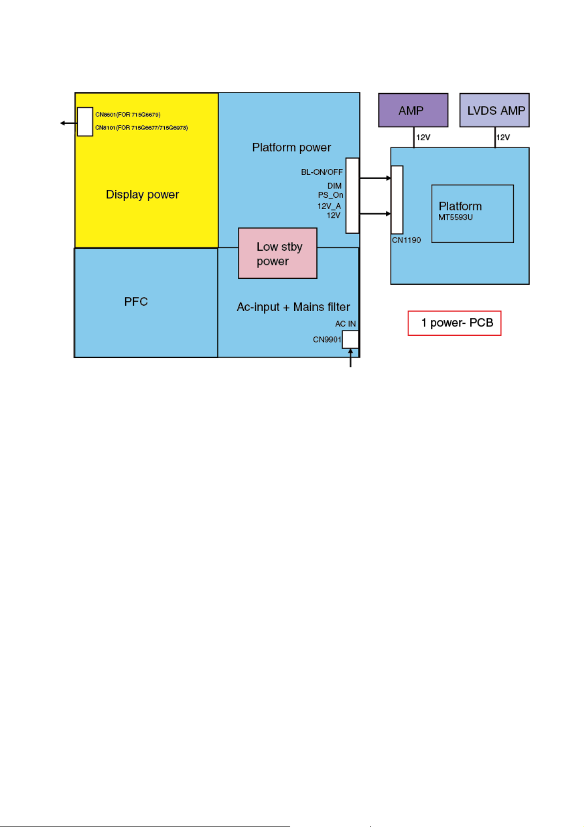
6.2 Power Supply
Power architecture of this platform.
6.2.1 Power Supply Unit
All power supplies are a black box for Service. When defective, a new board must be ordered and the defective one must be returned, unless the main fuse
of the board is broken. Always replace a defective fuse with one with the correct specifications! This part is available in the regular market.
Consult the Philips Service web portal for the order codes of the boards.
Important delta’s with the platform are:
• New power architecture for LED backlight
• “Boost”-signal is now a PWM-signal + continuous variable
The control signals are:
• PS-ON
• Lamp “on/off”
• DIM (PWM) (not for PSDL)
In this manual, no detailed information is available because of design protection issues.
• +8.5V output (standby mode)
• +12 output (on-mode)
• +12V_audio (audio AMP power)
• Output to the display; in case of
- IPB: High voltage to the LCD panel
- PSL and PSLS (LED-driver outputs)
- PSDL (high frequent) AC-current.
6.2.2 Diversity
The diversity in power supply units is mainly determined by the diversity in displays.
The following displays can be distinguished:
• CCFL/EEFL backlight: power panel is conventional IPB
• LED backlight:
- side-view LED without scanning: PSL power panel
- side-view LED with scanning: PSLS power panel
- direct-view LED without 2D-dimming: PSL power panel
Page 29
- direct-view LED with 2D-dimming: PSDL power panel.
PSL stands for Power Supply with integrated LED-drivers.
PSLS stands for a Power Supply with integrated LED-drivers with added Scanning functionality (added microcontroller).
PSDL stands for a Power Supply for Direct-view LED backlight with 2D-dimming.
6.3 DC/DC Converters
The on-board DC/DC converters deliver the following voltages(depending on set execution):
• +3V5-SB, permanent voltage for the Stand-by Power system and WIFI
• +3V3-STANDBY,voltage for IR/Key board
• +12V, input from the power supply for the panel common(active mode)
• +12V, input from the power supply for LNB supply
• +3V3-EMMC, +V-EMMC-IO, voltage for EMMC when TV on
• +1V5-DDR, +VREF-A2-DQ,, +VREF-A2-CA, voltage for DDR
• TUNER_3V3, supply voltage for tuner
• +5V-SW, input intermediate supply voltage for USB Power
• +12V-AUDIO1 for the AUDIO AMP
• +3.3VA_T2, +1.2V_T2 voltage for Demodulator IC channel decoder
• +3V3-WIFI,voltage for WIFI
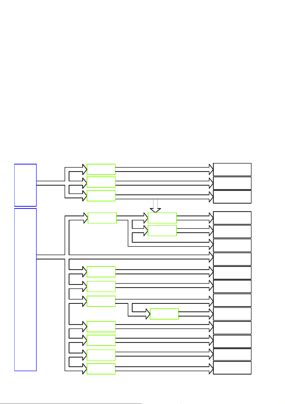
6.3.1 Power tree
+3V5-SB
+12V
51 mA at standby mode.
260 mA
+3V5-SB
+3V5-SB
+3V5-SB
+12V
+12V
+12V
+12V
+12V
RT9048GSP
RT9187GSP
RT9193-33GB
G5318RE1D
G5318RE1D
RT7277GSP
RT7297CHZSP
+3V3-WIFI
+3V3-LAN
+3V3-STANDBY
+5V_SW
+5V_SW
+5V_SW
+1V0-VCCK
DV12
+3V3/ +3V3-AVDD
power for RC off
RT8079ZQW
AZ1117D-3.3
46 mA at standby mode.
+1V5-DDR
+3V3_TUNER
27.5 mA
600 mA
WiFi & BT/ VCC
MT5593U+/ AVDD33-ETH
MT5593U+/ AVDD33-STB
MT5593U+/ DDRV
DDR (X 5)/ VDD
TUNER/ TU3.3V
CI/ VCC
USB/ +5V-USB
T-CON/ Panel VCC
AUDIO/ VCC
MT5593U+/ VCCK
MT5593U+/ AVDD10_DDR
DEMOD/ VDD-core
MT5593U+/ AVDD33-LVDS/
VCC-3V3
NT72333/ PWR-3.3V
G9661
+1V0-AVDD
MT5593U+/ AVDD10
Tuner/ VCC for LNB
(Satellite)
NT72333/ Core 1.1V
NT72333/ DDR 1.1V
NT72333/ VDD2.5V
NT72333/ DDR 1.8V
+12V
+12V
+12V
+12V
MP8124DF
G5318RE1D
RT7277GSP
SY8104ADC
+3V3-AVDD
TUNER_LNB
+1V1-NT
+2V5-NT
+1V8-NT
Page 30

6.3.2 Power layout SSB
Power SSB Top View
Page 31

Power SSB Bottom View
Page 32

6.4 Front-End Analogue and DVB-T, DVB-C;ISDB-T reception
6.4.1 DVB-C part
The Front-End for analogue tuner consist of the following key components:
• TUNER EUROPE TDSY-G480D
• TUNER EUROPE TDQS-A701F
• SCALER MT5593UGIJ HSBGA-900 Processor
Below find a block diagram of the front-end application for DVB-C part.
6.4.2 DTB-T2 part
The Front-End for DVT part consist of the following key components:
• TUNER EUROPE TDSY-G480D
• TUNER EUROPE TDQS-A701F
• SCALER MT5593UGIJ HSBGA-900 Processor
• DEMODULATOR Si2169-C50-GMR QFN-48
Below find a block diagram of the front-end application for DTV part.
6.5 HDMI
Refer to below for the application.
Page 33

The following HDMI connector can be used:
• HDMI 1: HDMI input ( TV digital interface support HDMI1.4/HDCP1.3) with digital audio/PC DVI input/ARC
• HDMI 2: HDMI input ( TV digital interface support HDCP) with digital audio/PC DVI input/ARC
• HDMI 3: HDMI input ( TV digital interface support HDMI1.4/HDCP1.3) with digital audio/PC DVI input/ARC
• HDMI 4: HDMI input ( TV digital interface support HDMI1.4/HDCP1.3) with digital audio/PC DVI input/ARC
• +5V detection mechanism
• Stable clock detection mechanism
• MHL 2.0 function only for HDMI4
• Audio return channel(ARC)
• TMDS output control
• HPD control
• CEC control
6.6 Video and Audio Processing - MT5593UGIJ
The MT5593UGIJ is the main audio and video processor (or System-on-Chip) for this platform. It has the following features:
• ATSC /DVB-T /DVB-C/DTMB demodulators
• Ture 120HZ Full HD MJC
• Power CPU core
• 3D graphic support OpenGL ES 1.1/2.0
• A muti-standard video decoder
• A transport de-multiplexer
• One HDMI 2.0 receiver with 3D support
• MHL2.0& Standby charging
• 2D/3D converter
• Rich format audio codec
• Local dimming (LED backlight)
• Ethernet MAC+PHY
• TCON
• Panel overdrive control
• Four-link LVDS, mini-LVDS,V-by-one, EPI
The MT5593UGIJ family consists of a DTV front-end demodulator, a backend decoder and a TV controller and offers high integration for advanced
applications. It integrates a transport de-multiplexer, a high definition video decoder, an audio decoder, a four-link LVDS transmitter, a mini-LVDS
transmitter, a V-by-one transmitter, an EPI transmitter, and an NTSC/PAL/SECAM TV decoder with 3D comb filter(NTSC/PAL).
The MT5593UGIJ enables consumer electronics manufacturers to build high quality, low cost and feature-rich DTV.
The MT5593UGIJ family supports Full-HD MPEG1/2/4/H.264/VC1/RM/AVS/ and H.264/HEVC video decoder standards, and JPEG. The MT5593UGIJ also
supports Media Tek MDDi de-interlace solution which can reach very smooth picture quality for motions. A 3D comb filter added to the TV decoder recovers
great details for still pictures. The special color processing technology provides a natural, deep colors and true studio quality video. Moreover, the
MT5593 family has built-in high resolution and high-quality audio codec.
The MT5593UGIJ family provides consumers with and Full-HD 120Hz experience. It integrates high-quality Full-HD ME/MC technology.
The MT5593UGIJ family supports ASTC,DVB-T and DVB-C,DTMB demodulation functions. It reserves transport stream inputs for external demodulators
for other countries or areas.TV maker can easily port the same UI to worldwide TV models. First-class adjacent and co-channel rejection capability grants
excellent reception. Professional error-concealment provides stable, smooth and mosaic-free video quality
Page 34

7. IC Data Sheets
7.1 MT5593UGIJ (IC U9400)
Page 35

Page 36

7.2 SI2169-C50 (IC U201)
Page 37

7.3 TAS5760LDDCAR (IC U5100)
Page 38

8.Circuit Diagrams
8.1 A 715G7350 PSU(For 43” 6432 Series)
8-1-1 AC Input
F9902
F9901
NC
!
FB9901
BEAD
1 2
!
RV9901
680V
!
!
CN9901
NC/CONN
T5A H 250V
T5AL/250V
!
1
2
12
CN9902
AC 2P
FB9902
BEAD
CN9903
NC/CONN
L
L1N
2
NR9901
t
2R
12
!
C9913
220PF 250V
SG9901
NC/DSPL-501N-A21F
NR9902
2R
1 2
BR
t
!
C9901
4
1
L9901
12mH
3
2
!
470NF 27 5V
C9911
47pF 250V
!
!
470NF 2 75V
C9902
!
L9902
12mH
1
2
4
3
!
12
C9912
47pF 250V
SG9902
NC/DSPL-501N-A21F
C9914
220PF 250V
!
L9903
0.25mH
2
3
!
1
4
2
BD9901
TS10P06G-05
!
+
4
-
1
3
Vsin
N
N
HOT
For BD9901
HS9902
HEAT SINK
1
1 2
2
1
2
HS9901
NC/ HEAT SIN K
FB9904
NC/127R
COLD
!
C9922
NC/ 220PF 250V
1
4
3
D12D1
NC
NC
NC5D26D27NC
8
U9901
CAP004DG-TL
C9908
47pF
R9907
R9906
510K
510K
NC/510K
R9904
NC/510K
R9905
R9902
R9903
510K
510K
L
Page 39

8-1-2 PFC
Vsin
C9820
1UF 450V
FB9801
BEAD
1 2
L9801
240uH
5
1
R9805
20K 1/4W
43
!
R9807
10R 1/8W 5%
D9803
SS1060FL
R9808
33R 1/8W 5%
D9802
S8KC
R9809
10K 1/8W
D9805
S8KC
D9801
FMNS-1106S
FB9803
BEAD
1 2
Q9801
TK20A60W
C9808
NC/47PF
R9817
1M 1% 1/4W
R9802
1M 1% 1/4W
HV
+
C9801
68uF 450V
+
C9802
68uF 450V
R9811
NC/ 2Mohm 1/4W +/ -1%
R9818
NC/ 2Mohm 1/4W +/ -1%
C9804
10UF 50V
VCC_ON
+
R9812
24K9 1%
C9803
100N 50V
C9811
47P 50V
8
OUT7VCC
INV1COMP2RAMP3CS
R9806
2K 1/8W 1%
6
5
ZCD
GND
4
R9813
10K 1/8W
C9805
47nF 50V
U9801
LD7591T
R9810
1K 1/4W
C9807
220pF 50V
C9806
470NF 50V
R9801
0.1R
R9814
NC/0R05
C9809
330PF 50V
FB9802
BEAD
R9803
910K 1/4W
3
Q9802
BSS127
2
C9810
100N 50V
R9804
18.7K 1/8W 1%
1
1 2
NC/SMF12A
ZD9801
R9815
10K 1/4W
R9816
100KOHM
For Q9801, D9801
HS9801
HEAT SIN K
1
2
3
4
1 2
VCC_ON
NC/ 470PF 50V
C9812
R9819
NC/ 2Mohm 1/ 4W +/-1%
R9820
NC/ 15K 1/ 8W 1%
U9802
NC/LD8105
1
ISEN
2
GND
VSEN3IREF
VCC
OUT
PFC_OVP
+VCC1
6
5
4
R9821
NC/ 510R 1%
C9813
NC/ 100N 50V
D9804
NC/1N4148W
Page 40

8-1-3 Main Power
C9147
1NF
HV
ZD9105
BZT52-B39
BR
ZD9104
BZT52-B39
R9154
1 2
620K +-1% 1/4W
R9153
620K +-1% 1/4W
1 2
R9152
620K +-1%
4.7M 5% 1/8W
R9151
0R05
1
2
C9150
R9150
4.7uF 50V
47K 1%
C9113
2.2nF 50V
For Q9101
HS9101
HEAT SINK
1
2
3
4
R9156
U9101
SSC3S121A
FB/OLP
BR
ST4DRV
GND
VCC
OCP
470PF 50V
C9146
1.5NF
R9157
0 OHM +-5% 1/8W
8
7
6
5
C9111
GND1
NC/GND
GND
GND
GND
GND4
NC/GND
GND
GND
GND
GND7
GND
1
VCC_ON
D9103
SS1060FL
R9105
200OHM
1
2
3
1
2
3
+VCC1
R9113
82 OHM
10K OHM
GND2
NC/GND
GND
GND
GND
GND5
NC/GND
GND
GND
GND
GND8
GND
GND
GND
GND
Q9102
BTC4672M3
C9114
10UF 50V
+VCC1
R9111
10 OHM
R9110
1
2
3
1
2
3
1
2
3
C9120
NC/2.2NF
+
R9116
GND3
NC/GND
GND
GND
GND
GND6
NC/GND
GND9
GND
GND
GND
GND
PFC_OVP
20K
R9147
82KOHM +-5%
R9142
22R
D9102
SARS01-V1
Q9101
TK11A 65D
R9109
0.3R 2W
1
2
3
1
1
2
3
R9115
3K
!
ZD9102
BZT52-B16
43
1 2
C9149
NC/47PF
PG1010R
R9155
5.1 OHM 1/4W
C9139
100N 50V
R9117
1K 1/4W
D9108
1N4148W
12
U9103
EL817M(X)
D9104
DV5
R9112
3.3 OHM
C9102
+
47UF 50V
R9120
10K 1/4W
+VCC1
Q9103
MMBT3906
R9119
10K OHM
Q9104
2N7002K
!
6
5
4
2
1
FB9101
127R
1 2
FB9103
BEAD
!
R9118
1K5 +-1%
C9115
100N 50V
T9101
POWER X'FMR
12
43
C9112
NC
R9122
100 OHM 1/4W
R9121
510K 1% 1/8W
COLDHOT
C9923
330pF 250V
!
C9921
680PF 250V
R9123
1K5 +-1% 1/8W
12
ZD9103
BZT52-B15
1 2
7
11
8
10
U9102
EL817M(X)
C9116
1uF
12VS
!
33K +-1% 1/4W
C9126 100N 50V
12VS
R9124
1K 1/4W
U9104
TL431G-AE2-R
PS_ON
R9143
C9127 100P 50V
R9135
27 OHM
R9137
27 OHM
R9139
27 OHM
R9125
1K 1/8W 1%
C9128
100N 50V
1
2
3
C9129
47pF
R9134
27 OHM
R9136
27 OHM
R9138
27 OHM
R9133
10K 1/4W
C9117
470NF 50V
U9105
Timin g
Pred
VR
MOSG- C
Adj4GND
SP6018ES8RGB
Q9106
TK22A10N1
12VS
12VS
SYNC
Vdd
D9105
SK510C
C9125
1N 50V
R9126
9K1 1/8W
R9127
2K2 1/8W
R9128
1K5 OHM
SYNC
8
7
6
5
12
R9132
5.1K 1/4W
SYNC
FB9301
BEAD
1 2
4R7 1/4W 5%
C9130
4.7UF
R9140
5K1 +-5%
4.7UF 25V
C9124
1N 50V
R9144
C9301
R9129
6.2K
C9131
4.7UF
Q9105
2N7002K
U9106
NC/L78L12ABUTR
3
IN
GND
OUT
1
D9106
SS1060FL
R9141
10 OHM
C9118
1N 50V
C9303
100NF 50V
12VS
R9145
2
DV5
R9130
100K
R9131
100K
1
2
2200uF 25V
12V/16V
C9304
100NF 50V
U9307
SY8120B1ABC
BS
GND
FB3EN
C9132
BL_O/F
12VA/16VA
LX
IN
C9305
1NF 50V
C9143
6
5
4
+
C9135
470UF 25V
1uF
C9122
470UF 25V
1uF
1 2
R9301
+
C9136
C9121
1N 50V
C9123
1uF 50V
ZD9301
BZT52-B5V1
3K
3D_ON
+
C9144
1uF 50V
L9301
47uH
+3.5/+5V
R9302
10K
R9303
1.96K
100KOHM
C9137
NC/1uF
C9138
100N 50V
R9146
100K
Q9108
2N7002K
2
4
6
8
10
12
14
16
100PF 50V
CN9101
CONN
C9306
Q9107
MTB15P04J3
1
3
5
7
9
11
13
15
C9307
10UF 16V
C9140
100N 50V
L9102
3UH
L9103
3UH
R9149
100 OHM
R9148
510K
For Q9106
C9119
1N 50V
+
C9308
C9309
10UF
100UF 25V
D9107
SS1060FL
HS9102
HEAT SINK
+
C9141
470UF 25V
+
C9142
470UF 25V
1
2
3
4
DIM
PS_ON
12VA/16VA
12V/16V
+3.5/+5V
12VA/16VA
12V/16V
PS_ON
Page 41

8-1-4 LED
IC_VCC
NC/10K OHM
HV
470NF 50V
NC/AOD8N25
R8659
Q8604
C8623
-VLED2
R8605
0.1R
-VLED1
1 2
C8648
1NF
U8601
PF6002AS
1
CT
2
FB
3
CS
GND4OUT
R8616
470 OHM 1/4W
C8624
470P 50V
C8627
1N 50V
R8662
NC/3.3M 1/4W
R8621
NC/3.3M 1/4W
R8622
NC/240K 1/ 8W
J917
NC/JUMPER
VCC
VCC
NC
100N 50V
R8608
200 OHM 1/4W
8
7
6
5
C8625
C8601
NC/22pF 50V
1 2
J930
JUMPER
VCC_ON
C8621
1.5NF
200 OHM 1/4W
R8609
D8609
SS1060FL
NC/2.2NF
200 OHM 1/4W
R8618
47OHM
IC_VCC
C8622
R8610
DIM
R8617
22R
10K 1/4W
200 OHM 1/4W
R8619
R8611
R8606
82KOHM +-5% 2WS
R8612
200 OHM 1/4W
R8613
200 OHM 1/4W
D8608
SARS01-V1
Q8601
TK11A6 5D
R8601
0R18 5%
BL_O/F
R8620
0R05
NC/100P 50V
R8607
82KOHM +-5% 2WS
200 OHM 1/4W
C8626
NC/47PF
C8603
NC/100P 50V
C8604
R8614
R8615
200 OHM 1/4W
new part(PQ38)
For Q8601
HS8603
HEAT SINK
1
2
3
4
C8628
100P 50V
NC/100 P 50V
U8605
TPV10 1AD
1
DIM
2
EN
3
VCC
LED4GND
C8613
100N 50V
U8606
TPV10 1AD
1
DIM
2
EN
3
VCC
LED4GND
C8605
100N 50V
HOT
NC/1K OHM
U8603
EL817M(X)
!
C8617
COMP
ISET
COMP
GM
ISET
!
POWER X'FMR
3
4
5
R8638
C8620
NC/4N7 50V
43
ZD8601
BZT52-B30
8
7
GM
6
5
8
7
6
5
COLD
T8601
2
1 2
R8625
1.2R 1%
R8631
1.2R 1%
6
7
10
11
GND
12
U8604
TL431G-AE2-R
R8624
1.2R 1%
R8632
1.2R 1%
For D8605,D8606
D8605
FMNS-1106S
D8606
FMNS-1106S
R8651
300 OHM 1/4W
300 OHM 1/4W
R8649
300 OHM 1/4W
300 OHM 1/4W
R8647
300 OHM 1/4W
R8663
300 OHM 1/4W
12VS
3
U8602
IN
NC/L78L09ACUTR
OUT
1
C8602
NC/100 N 50V
D8603
NC/1N4148W
R8639
3K9 1/8W 5%
R8637
10K OHM
R8626
1.2R 1%
R8633
1.2R 1%
D8602
1N4148W
R8630
20K
R8627
1.2R 1%
R8634
1.2R 1%
R8642
0R05 1/4W
ZD8602
NC/BZ T52-B15
1 2
R8623
0R05
R8636
0R05
HS8604
HEAT SINK
R8652
R8650
R8648
300 OHM 1/4W
R8664
300 OHM 1/4W
C8619
0.1uF 50V
C8618
100P 50V
1
2
3
4
C8632
100PF 500V
C8633
100PF 500V
R8641
0R05 1/4W
1 2
ZD8603
NC/BZT52-B15
R8628
7K5 1%
C8614
1uF
C8616
1uF
R8640
0R05 1/4W
ZD8604
NC/BZT52-B15
1 2
R8629
13K 1% 1/4W
+
C8634
120UF 100V
VLED
+
C8635
120UF 100V
ZD8605
BZT52-B9V1
1 2
12VS
C8636
+
NC/47uF 100V
ZD8606
BZT52-B16
1 2
C8629
1uF
R8643
15K
VLED
R8653
R8655
100K
100K
R8654
R8656
100K
100K
D8604
1N4148W
Q8605
MMBT390 6
R8644
10K 1/4W
Q8606
2N7002K
For U8605
For U8606
-VLED2
+VLED
C8630
1uF
HS8601
HEAT SINK
HS8602
HEAT SINK
C8631
100N 50V
1
2
1
2
R8657
100K
R8658
100K
L8601
3UH
BL_O/F
+VLED
-VLED1
1 2
C8637
47uF 100V
IC_VCC
R8645
100 OHM
R8646
510K
NC/JUMPER
J904
JUMPER
+
CN8601
CONN
1
2
3
4
5
12
J925
JUMPER
J924
1 2
6
7
8
9
10
11
12
For LPB function
+VLED
C8638
C8639
2.2NF
2.2NF
R8660
68K 1/8W 1%
R8661
36K 1/8W 1%
Page 42

8.2 A 715G6973 PSU(For 49”/55” 6432 & 49” 7272 Series)
8-2-1 AC Input
CN9901
NC/CONN
F9901
T5AH/250V
1 2
3 4
F9902
NC
CN9902
12
1
2
AC SOKET
F9903
NC
FB9901
BEAD
C9911
47pF 250V
C9912
47pF 250V
12
RV9901
680V
NR9901
1R
t
12
FB9902
BEAD
CN9903
NC / CONN
SG9901
NC/D SPL-501N-A21F
L1N
2
t
R9901
510k 1/2W
C9913
220PF 250V
3
1
L9901
12mH
4
3
C9901
470NF 275V
12
1
2
4
D12D1
C9907
NC
NC
8
R9902
510k 1/2W
47PF
NC5D26D27NC
U9901
CAP004DG-T L
C9902
470NF 275V
NR9902
1R
1 2
C9914
220PF 250V
t
4
3
L9902
12mH
1
2
SG9902
NC/D SPL-501N-A21F
R9905
NC/510K 1/4W
R9904
NC/510K 1/4W
R9903
NC/510K 1/4W
R9908
NC/ 510K 1/ 4W
R9907
NC/ 510K 1/ 4W
R9906
NC/ 510K 1/ 4W
NR9903
1R
R-
12
BD9901
GBJ1008-FU C
4
BO
2
Vsin
+
-
1
3
N
GND1
GND
FB9903
BEAD
GND2
GND
1
GND4
GND
1
1
C9916
1NF 250V
1 2
HS9901
HEAT SINK
1
2
3
4
Page 43

8-2-2 PFC
Vsin
C9803
1UF 450V
R9801
0.1R 3W
C9804
1UF 450V
R9802
0.1R 3W
R-
R9809
27K 1/8W 1%
1uF
C9806
C9807
0.47uF 50V
FB_PFC
R9810
22K 1/8W 1%
1
BD9801
KBP208G-C
+
2
C9808
10N 50V
3
R9814
10R 1/8W 5%
C9813
3.3nF 50V
L9801
220uH
4
C9811
100N 50V
R9813
NC / 24K 1/ 8W 1%
6
+VCC2
12
HS9801
HEAT SIN K
C9812
47PF 50V
R-
1
2
3
4
R9816
10K 1/8W 1%
FB_PFC
C9810
+
10UF 50V
D9802
SS1060
R9815
33R 1%
R9812
47R 1%
12
ZD9801
BZT52-B3V6
-
4
U9801
SSC-2005S
R9811
33K 1/8W 1%
1
FB
2
COMP
3
RT
RDLY4CS
C9809
10N 50V
VCC
OUT
GND
8
7
6
5
C9814
47PF
D9801
FMNS-1106S
Q9801
NC/47PF
TK18A60V
C9815
12
C9805
C9818
47PF
FB9904
BEAD
R9819
NC/0R05
1NF 50V
R9803
1MOHM +-1% 1/4W
R9804
680K OHM +-1% 1/4W
R9805
680K OHM +-1% 1/4W
R9806
100K 1%
R9807
470K 1%
R9808
16K +-1% 1/8W
Q9802
AO3160
C9817
100N 50V
+
C9801
R9818
10K 1/8W 1%
+
82uF 450V
R9817
10K 1/8W 1%
C9816
C9802
1NF
82uF 450V
For Power Sav i ng
Vbus
+VCC2
Page 44

8-2-3 Main power
Vbus
FB_12V
BO BO
R9108
3.3M 1/4W
FB_12V
D9107
NC/1N4148W
12VS
R9102
R9103
3.3M 1/4W
4N7 50V
C9101
R9104
C9130
NC/4. 7N F 50V
+
470uF 25V
C9301
C9110
1500UF 35V
U9106
NC/AS78L12RTR-G1
3
IN
2
GND
OUT
C9131
NC/100N 50V
1
8
7
6
5
1uF
DV5LED_OVP
R9134
12VS
R9118
100K 1/8W 1%
C9111
NC/1uF
C9112
NC/1uF
Timi ng
SYNC
Vdd
MOSG- C
GND
U9105
SP6018ES8RGB
Q9107
MMBT3906
10K 1/8W 1%
1
2
Pred
3
VR
4
Adj
R9135
10K 1/8W 1%
Q9108
2N7002K
C9122
0.1uF 50V
Q9103
AOD4185
R9119
100K 1/8W 1%
R9136
10K 1/8W 1%
Q9104
2N7002K
47P 50V
C9125
R9138
510K 1% 1/8W
L9101
3UH
L9102
3UH
C9117
0.1uF 50V
C9126
0.1uF 50V
12VS
R9137
100 OHM 1/4W
1 2
100 OHM 1%
R9121
R9144
47K +-1% 1/4W
C9127
100PF 50V
ZD9103
SS1060
R9120
510K 1% 1/8W
3D_ON
+12V_A
+12V
+3.5V
+
C9113
470UF 25V
+
C9115
470UF 25V
C9128
0.1uF 50V
PS_ON
+12V_A
1uF
C9114
+12V
1uF
C9116
DV5
CN9101
CONN
2
1
4
3
6
5
8
7
10
9
12
11
14
13
16
15
C9133
10N 50V
R9145
0R05 1/4W
C9129
1NF 500V
PS_ON
+12V_A
+12V
+3.5V
DIMBL_ON/OFF
T9101
POWER X'FMR
6
C9106
2.2NF
+VCC1
C9104
0.1uF 50 V
R9105
C9119
220N 50V
R9126
2K2 1/8W 1%
R9127
1K5 +-1% 1/8W
C9304
1nF 50V
D9108
1N4148
+
+
C9132
C9105
10UF 50V
D9101
1N4148W
R9106
82 OHM
12VS
R9125
9K1 1/8W 1%
R9128
6.2K 1%
L9301
47uH
C9306
2.2nF 50V
R9302
20K 1/8W 1%
R9303
C9305
30 OHM 1/4W
2.2nF 50V
R9147
330K +-1% 1/4W
R9148
NC
NC
VCC
12VS
BZT52-B15
1 2
ZD9301
BZT52-B4V7
1
2
3
U9301
AOZ3015AI
8
7
6
5
R9122
1K5 +-1% 1/8W
C9118
12
PGND
VIN
AGND
VCC4FB
330K +-1% 1/4W
R9149
330K +-1% 1/4W
R9146
0R05
R9123
R9124
1K 1/8W 1%
U9103
AS431AN-E1
NC/1uF
FB_SB
8
EN
7
LX
6
COMP
5
10ohm +/-1% 1/8W
R9107
1Kohm +-1% 1/4W
4.7K 1/8W
R9301
3K 1/8W +/-1%
3.3M 1/4W
U9101
LD5532
1
BNO
2
COMP
3
CS
GND4OUT
C9102
1000pF 50V
100K 1/8W 1%
C9103
330P 50V
U9102
EL817M(X)
1
4
23
Q9109
NC/MMBT3906
1uF
C9302
ZD9104
C9303
0.1uF 50V
D9102
FR107G-A0
100UF 50V
Q9105
2N7002K
R9304
30 OHM 1/4W
R9111
82K 2W
R9110
2R2 +-5% 1/4W
R9150
22R 5%
D9103
FR107G-A0
Q9101
TK11A65D
R9109
10K 1/8W 1%
0.2R
R9101
R9129
10K OHM +-5% 1/8W
C9120
R9130
0.1uF 50V
330K 1/8W 5%
+
1uF
1uF
C9307
C9308
C9309
5
7
4
11
2
8
1
10
HS9101
HEAT SINK
1
2
3
4
HS9102
HEAT SINK
1
2
3
4
DV5
+3.5V
R9305
11K 1/8W 1%
R9306
0R051/8W
R9307
470UF 25V
3K 1/8W +/-1%
FB_SB
+VCC1
+VCC2
R9112
R9113
27 OHM
27 OHM
R9115
R9116
27 OHM
27 OHM
2N2 50V
2N2 50V
C9121
10UF 50V
R9114
R9117
C9107
C9108
D9104
SK810C
12
Q9102
AOTF298L
27 OHM
R9139
8.2K 1/4W
27 OHM
R9140
5K1 1/8W 1%
R9131
3K
Q9106
BTC4672M3
+
R9132
+
+
C9109
1500UF 35V
12VS
R9141
5K1 1/8W 1%
R9143
4R7 1/4W 5%
R9142
10ohm +/-1% 1/8W
1uF
C9124
C9123
D9105
SS1060
1 2
R9133
2K 1/8W 1%
U9104
EL817M(X)
4
ZD9105
BZT52-B15
1 2
100KOHM +-1% 1/4W
D9106
1N4148W
1
23
Page 45

8-2-4 LED Driver
N
C
R8101
+VCC2
For Power Sav ing
R8162
10K 1/8W 1%
R8163
10K 1/8W 1%
FB_LLC
C8101
1NF
Q8106
AO3160
C8142
0.1R
100N 50V
Vbus
R8102
R8103
R8104
R8161
NC/0R 05
R8105
R8116
C8114
R8151
0 OHM +-5% 1/8W
1.5R
R8136
R8137
R8152
0 OHM +-5% 1/8W
1.5R
R8140
R8153
0 OHM +-5% 1/8W
1.5R
R8144
R8154
0 OHM +-5% 1/8W
R8148
1R 1%
HS8101
HEAT SINK
1
2
3
4
HS8102
HEAT SINK
1
2
HS8103
HEAT SINK
1
2
HS8104
HEAT SINK
1
2
HS8105
HEAT SINK
1
2
U8105
TPV101D
8
COMP
7
GM
6
ISET
5
1.5R
1.5R
R8138
U8106
TPV101D
8
COMP
7
GM
6
ISET
5
1.5R
1.5R
R8141
R8142
U8107
TPV101D
8
COMP
7
GM
6
ISET
5
1.5R
1.5R
R8146
R8145
U8108
TPV101D
8
COMP
7
GM
6
ISET
5
1.5R
1.5R
R8149
R8150
+VLED
-VLED1
R8158
0R05 1/4W
-VLED2
+VLED
+VLED
10
3D_ON
BL_ON/OFF
1
DIM
2
EN
3
VCC
LED4GND
C8127
0.1uF 50V
1
DIM
2
EN
3
VCC
LED4GND
C8129
0.1uF 50V
1
DIM
2
EN
3
VCC
LED4GND
C8131
0.1uF 50V
1
DIM
2
EN
3
VCC
LED4GND
C8134
0.1uF 50V
12
14
DIM
1uF
C8128
1uF
C8130
1uF
C8132
1uF
C8135
C8141
100PF 50V
2
4
6
8
CN9102
NC/CONN
NC/0 OHM +-5% 1/ 8W
R8156
C8140
1NF 500V
R8155
10K 1/4W
1
3
5
7
9
11
13
R8157
10K 1/4W
1
2
3
4
5
6
7
8
9
10
11
12
-VLED1
-VLED2
-VLED1
CN8101
CONN
BL_ON/OFF
TPV101_VCC
-VLED2
3D_ON
+VLED
+12V
DIM
+
Q8105
MMBT3906
5K1 1/8W 1%
1K 1/8W 1%
C8116
220UF 100V
R8132
5K1 1/8W 1%
U8104
AS431AN-E1
VLED1
L8101
3UH
+
R8118
75K
C8117
220UF 100V
+12V
VLED1
R8160
R8131
1K 1/8W 1%
62K 1/8W 1%
R8133
30K 1/8W 1%
R8134
4.3K OHM 1%
TPV101_VCC
Q8108
2N7002K
C8143
0.47UF 50V
+
C8118
C8126
0.1uF 50V
R8171
1 MOHM +-1% 1/8W
R8172
510K 1% 1/8W
C8119
1NF 500V
39uF 160V
FB_LED
+VLED
C8120
0.1uF 50V
C8121
0.1uF 50V
1uF
C8136
1.5R
R8135
1uF
C8137
1.5R
R8139
1uF
C8138
1.5R
R8143
1uF
C8139
R8147
1R 1%
D8104
3
VS
1M5 1/4W 1%
1M5 1/4W 1%
1M5 1/4W 1%
+
C8102
18K 1/8W 1%
0.1uF 50V
C8105
0.47UF 50V
R8117
2K43 1/8W 1%
4
10N 50V
C8115
4.7uF 10V
U8102
EL817M(X)
FB_LLC
+VCC2
C8103
22UF 50V
NC
R8106
+12V
D8106
SS1060FL
470R 1%
R8119
4.3K OHM 1%
C8104
1
23
0.1uF 50V
1 2
C8110
R8107
470R 1/8W 1%
C8106
560PF 50V
VLED1
1 2
1 2
D8107
SS1060FL
R8120
NC/3K 1/ 8W 5%
ZD8104
BZT52-B30
D8101
R8109
UF4007
10ohm +/-1% 1/8W
U8101
SSC9522S
1
18
Vsen
NC
2
17
Vcc
NC
3
16
FB
VGH
4
15
GND
VS
5
14
Css
VB
6
13
OC
NC
7
12
RC
NC
8
11
Reg
VGL
10
RV9COM
1uF
C8111
C8112
5PF
47P 50V
ZD8102
BZT52-B16
ZD8103
BZT52-B16
C8124
NC/0.47U F 50V
R8108
180R 1%
C8123
0.1uF 50V
U8103
AS431AN-E1
1uF
C8133
C8122
NC
R8125
470K +-5% 1/8W
C8107
1nF 50V
1 2
D8102
R8110
SS1060FL
10ohm +/-1% 1/8W
R8111
47R 1%
D8103
R8113
SS1060FL
10ohm +/-1% 1/8W
R8114
47R 1%
ZD8101
BZT52-B15
VS
C8108
100PF1KV
VLED1
R8121
750K 1%
R8122
R8124
75 KOHM +-1% 1/8W
150K 1/8W +/-1%
R8123
100K 1/8W 1%
FB_LED
Q8101
TK10A50D
R8112
10K 1/8W 1%
Q8102
TK10A50D
C8113
R8115
100PF
10K 1/8W 1%
+12V
1
4
T8101
POWER X'FMR
C8109
27NF
9
6
5
10
7
12
11
8
LED_OVP
D8108
SS1060FL
Q8103
MMBT3904
D8110
1N4148W
2 3
Q8107
1
R8165
510 OHM +-1% 1/8W
LMBT3906LT1G
R8166
3K3 1/8W 1%
U8109
AS431AN-E1
FMX-23S
2
1
3
D8109
FMX-23S
2
1
3
D8105
FMX-23S
2
1
DV5 +12V
R8126
0 OHM +-5% 1/8W
R8127
2K 1/8W 1%
Q8104
MMBT3906
R8128
1K 1/8W 1%
C8144
1uF
C8145
1uF
VLED1
R8129
NC / 0 OHM +-5% 1/8W
R8130
1K 1/8W 1%
C8125
0.1uF 50V
TPV101_VCC
R8167
47K 1/8W 1%
R8168
43K 1/8W 1%
47K 1/8W 1%
R8169
9K1 1/8W 1%
R8159
R8164
R8170
Page 46

8.3 A 715G7857 PSU(For 43” 7202 Series)
8-3-1 AC Input
T5.0AH/250V
F9901
FUSE
1 2
3 4
F9902
NC / 5A 250V
!
!
FB9901
BEAD
1 2
!
CN9902
NC/CONN
1
2
12
CN9901
AC 2P
VXB
CAP004DG-TL
U9901
1
!
3
R9903
510K 1/4W
4
680V
RV9901
!
FB9902
BEAD
R9904
510K 1/4W
For BD9901
HS9901
HEAT SIN K
1
2
VXC
330PF 250V
C9903
NC/DSPL-501N-A21F
SG9901
VXB
CN9903
NC/CONN
L1N
2
BR
!
!
NC / 47pF 250V
C9901
NC / 47pF 250V
C9902
!
12
470NF 275V
!
C9905
2
3
L9901
12mH
1
4
!
1 2
NR9901
2R
t
!
C9906
470NF 275V
C9904
330PF 250V
L9902
12mH
1
2
4
3
SG9902
NC/DSPL-501N-A21F
!
1 2
NR9902
2R
t
2
BD9901
TS10K80-02
3
VXA
!
+
1
Vsin
-
4
C9907
47PF
D12D1
NC
NC
R9905
NC / 510K 1/4W
NC5D26D27NC
8
R9907
510K 1/4W
VXA
R9906
NC / 510K 1/ 4W
R9908
510K 1/4W
Page 47

8-3-2 PFC
2
+
4
-
1
Vsin
FB9891
BEAD
1 2
C9801
1UF 450V
C9810
100N 50V
VCC_ON
!
10PF 50V
+
R9807
10K 1/8W
L9801
170uH
3 5
R9809
24K 1/4W
C9808
C9809
10UF 50V
1 4
8
R9811
10 OHM
R9810
2K 1/8W 1%
6
5
ZCD
OUT7VCC
GND
INV1COMP2RAMP3CS
4
R9808
27K 1/8W 1%
U9801
LD7591T
KBP206G X0G
FB9801
BEAD
12
D9803
SS1060FL
R9812
47OHM
R9815
470 OHM 1/4W
C9811
1nF 50V
BD9801
12
3
Q9801
TK18A60V
10K 1/8W
D9802
FMNS-1106S
R9813
R9814
0.1R
C9805
NC/47PF
C9806
NC/100PF
FB9802
BEAD
1 2
R9804
NC/0R05
R9801
1M 1% 1/4W
R9802
1M 1% 1/4W
R9803
1M 1% 1/4W
3
Q9802
BSS127
2
C9814
100N 50V
HV
+
C9802
+
68UF 450V
C9803
68UF 450V
C9804
NC
For Q9801/D9802
HS9801
HEAT SIN K
1
2
3
4
R9816
1 2
ZD9801
NC/SMF12A
10K 1/8W 1%
R9817
100K 1/8W 1%
VCC_ON
1
C9813
100N 50V
C9812
470NF 50V
R9895
20K 1/8W 1%
C9815
470P 50V
R9806
680K 1%
Page 48

8-3-3 Standby
HV
U9301
LD5532
1
BNO
NC
2
COMP
NC
3
CS
VCC
GND4OUT
C9308
330P 50V
R9315
3.3M 1/4W
C9310
R9316
1NF
100K 1/8W 1%
C9311
4.7nF 50V
BR
8
7
6
5
R9301
330K 1/4W
R9302
330K 1/4W
R9303
330K 1/4W
R9311
1K 1/4W
R9314
3.3M 1/4W
C9301
1NF
R9304
0 OHM
D9304
SS1060FL
C9303
NC/1NF
R9309
10R 1/8W 5%
12
R9308
82 OHM
R9310
10K OHM 1/8W
R9313
3.3M 1/4W
C9302
2.2NF
R9306
39R 5%
D9301
SARS01-V1
TK11A65D
R9312
0.2R
BR
From AC N
Q9301
C9306
100N 50V
C9307
NC/47PF
R9305
82K 2W
R9348
39R 5%
D9393
1N4148W
+
C9305
10UF 50V
For Q9301
HS9301
HEAT SINK
1
2
3
4
D9302
FR107G-A0
R9307
2R7 1/4W
+
C9304
100UF 50V
+VCC1
U9102
EL817M(X)
!
6
5
4
2
1
FB9302
BEAD
FB9803
127R
1 2
43
COLDHOT
T9301
POWER X'FMR
220PF 250V
12
!
12VS
!
12
BZT52-B15
1 2
7
11
8
10
!
C9315
C9818
680PF 250V
R9346
3K3 1/8W 1%
ZD9302
C9340
NC/1uF
R9347
1K OHM
R9320
33K 1/4W
100N 50V
R9330
27 OHM 1/4W
R9331
27 OHM 1/4W
R9332
27 OHM 1/4W
R9345
1K 1/8W 1%
U9304
TL431G-AE2-R
C9333
100P 50V
C9334
R9333
27 OHM 1/4W
R9334
27 OHM 1/4W
R9335
27 OHM 1/4W
R9329
8.2K 1/4W
C9332
100N 50V
U9302
SP6018ES8RGB
1
Timi ng
2
Pred
3
VR
Adj4GND
C9335
47P 50V
Q9303
TK22A10N1
C9339
470NF 50V
SYNC
Vdd
MOSG- C
12VS
R9341
9K1 1/8W 1%
R9342
2K2 1/8W 1%
R9343
1.5KOHM +-1%
D9311
SK510C
8
7
6
5
12
C9330
1NF 500V
SYNC
D9312
SS1060FL
R9324
5K1 1/8W 1%
R9328
5.1K 1/4W
SYNC
R9321
4R7
4.7UF
C9336
4.7UF
R9323
10ohm 1/4W +/ -1%
C9331
1NF 500V
R9340
6.2K OHM 1/8W
Q9309
2N7002K
C9337
C9338
1N 50V
DV5
R9338
100K 1%
R9339
100K 1/8W
+
C9320
2200uF 25V
12VS
+
C9321
2200uF 25V
For Q9302
HS9302
HEAT SINK
1
2
3
4
+12V_A
BL_ON/OFF
+12V
For Q9303
3D_ON
C9342
1uF
HS9303
HEAT SINK
R9322
100KOHM 1/8W
1
2
3
4
10
12
14
16
C9341
1uF 50V
C9325
100N
C9324
NC/1uF
2
4
6
8
CN9101
CONN
Q9302
MTB15P 04F P
R9327
100K
Q9305
2N7002K
1
3
5
7
9
11
13
15
C9328
100N 50V
C9359
1uF 50V
R9326
510K 1/8W
R9337
0R05 1/4W
C9343
1N 50V
+3.5V/ +5V
L9302
3UH
SS1060FL
R9325
100 OHM 1/4W
L9303
3UH
D9313
PS_ON
+12V_A
+12V
+12V
+
C9326
470uF 25V
+12V_A
+
C9327
470uF 25V
PS_ON
DIM
VCC_ON
+VCC1
+
C9313
10UF 50V
Q9306
BTC4672M3
R9317
3K
EL817M(X)
R9318
20K 1/8W
ZD9301
BZT52-B16
U9306
FB9305
DV5
Q9308
R9364
10K OHM
MMBT390 6
R9363
1K5
R9365
2K 1%
LED_OV
D9314
1N4148W
R9366
0R05
!
12
43
1 2
Q9307
2N7002K
R9362
10K 1/8W 1%
C9329
100N 50V
12VS
R9360
100 OHM 1/4W
R9361
510K 1% 1/8W
PS_ON
12VS
1 2
C9350
470uF 25V
BEAD
+
C9351
1uF
ZD9303
BZT52-B4V7_R1_00001
12
U9305
AOZ3015AI
1
PGND
EN
2
VIN
LX
3
AGND
COMP
VCC4FB
C9352
100N 50V
C9353
1N 50V
R9351
8
7
6
5
R9352
20K
C9354
2N2 50V
3K
L9304
47uH
C9355
2N2 50V
+
R9353
30R 1%
R9354
30R 1%
C9356
470uF 25V
C9357
1uF
C9358
1uF
R9355
11K 1/8W 1%
R9356
0 OHM +-5%
R9357
3K 1/8W +/-1%
+3.5V/ +5V
Page 49

8-3-4 LED Driver
HV
VCC_ON
R8107
10K OHM
100K 1/8W
R8108
100N 50V
Q8103
BSS127
18K 1/8W
1
C8104
100N 50V
R8105
C8102
R8102
1M5 1/4W 1%
3
R8106
NC/0R 05 1/ 4W
2
C8103
100N 50V
VCC_ON
+
C8105
22UF 50V
1M5 1/4W 1%
R8101
0.1R 1W
R8103
R8104
1M5 1/4W 1%
R8110
47K +-1% 1/4W
C8107
4.7uF 10V
C8108
0.47UF 50V
C8109
1UF
VBoot
C8106
10NF 50V
R8120
NC
C8101
1NF
C8110
47P 50V
D8103
UF4007
C8111
5PF
C8113
560P 50V
D8111
NC/SS1060F L
R8109
470 OHM 1/4W
U8102
EL817M(X)
4
!
U8101
SSC9522S
1
Vsen
2
Vcc
3
FB
4
GND
5
Css
6
OC
7
RC
8
Reg
RV9COM
R8119
470OHM
+12V
ZD8109
BZT52-B30
C8112
1uF
R8138
1.5K OHM
1
23
R8111
10R 1/8W 5%
18
NC
17
NC
16
VGH
15
VS
14
VB
13
NC
12
NC
11
VGL
10
R8118
200 OHM +/-1%
C8137
NC
1 2
ZD8101
1 2
BZT52-B15
VLED
C8114
1N 50V
ZD8106
BZT52-B9V1
1 2
ZD8107
BZT52-B9V1
1 2
ZD8108
BZT52-B7V5
1 2
D8112
1N4148W
C8131
100N 50V
R8139
1K 1/8W 1%
U8104
TL431G-AE2-R
D8101
SS1060FL
R8112
47 +-5%
D8102
SS1060FL
R8115
47 +-5% 1/8W
C8128
100N 50V
R8113
10R 1/8W 5%
10R 1/8W
C8116
100PF1KV
R8114
10K 1/8W
TK10A50D
R8116
R8117
10K 1/8W
C8127
NC/100P 50V
C8129
NC
R8145
20K
Q8102
C8117
27NF
VLED
Q8101
TK10A50D
R8140
47K
R8141
47K
R8142
6.8K
C8115
NC/100PF
LED_OV
VBoot
For D8106/D8107
HS8102
HEAT SINK
1
2
3
4
3
R8131
5.1KR 1%
R8132
1K 1/8W 1%
C8146
100N 50V
D8110
1N4148W
1
2
3
1
3
1
1 2
U8106
TPV101D
DIM
EN
VCC
LED4GND
C8135
1uF 50V
D8106
FMXA-2202S
2
D8107
FMXA-2202S
2
ZD8105
BZT52-B20
COMP
GM
ISET
ZD8104
BZT52-B18
1 2
8
7
6
5
R8159
1.2R 1%
1 2
R8158
1.2R 1%
+
ZD8102
BZT52-B18
R8157
1.2R 1%
C8120
82uF 100V
For IC8105
HS8105
HEAT SINK/NC
R8160
0R05 1/4W
R8156
1.2R 1%
VLED
+
+
C8121
C8122
R8149
82uF 100V
82uF 100V
VLED
For IC8106
HS8106
HEAT SINK/NC
1
2
C8148
1uF
BL_ON/OFF
IC_VCC
-VLED-2
1
2
100K
R8171
10K 1/4W
DIM
C8140
NC/1N F 500V
T8101
EE39
7
8
!
1
5
6
2
3
4
9
10
D8109
SS1060FL
Q8106
MMBT390 4
R8150
13 K
BL_ON/OFF
DV5
IC_VCC
-VLED-1
DIM
R8135
0R05 1/4W
R8136
2K 1/8W 1%
1K 1/8W 1%
R8137
NC/1N F 500V
+12V
R8133
NC/0R 05 1/ 4W
R8134
1K 1/8W 1%
Q8107
MMBT390 6
C8132
100N 50V
R8172
10K 1/4W
C8145
L8101
3UH
C8136
C8141
100N 50V
GND1
GND3
GND2
NC
GND
NC
1
1
1
+
C8123
C8124
NC/1N F 500V
82uF 100V
+12V
1uF
U8105
TPV101D
1
2
3
C8147
1uF 50V
R8130
NC/510OH M
DIM
COMP
EN
VCC
LED4GND
GM
ISET
D8108
0 OHN
Q8104
NC/MMBT3906
R8129
NC/3K3 1/ 8W 5%
U8103
NC/TL431G-AE2-R
8
7
6
5
R8154
1.2R 1%
GND4
GND
1
C8126
100N 50V
R8153
1.2R 1%
C8125
100N 50V
C8157
NC/1uF
GND5
NC
1
C8134
NC/1uF
R8152
1.2R 1%
+VLED
GND6
NC
1
IC_VCC
R8151
1.2R 1%
GND7
GND
1
+VLED
R8155
0R05 1/4W
R8126
NC/43K
R8127
NC/43K
R8128
NC/13K
C8143
1uF
+VLED
-VLED-1
-VLED-2
+VLED
0R05 1/4W
R8125
NC/36K
R8121
R8122
0R05 1/4W
Q8105
NC/2N 7002K
C8133
NC/470N F 50V
IC_VCC
10
11
12
R8123
NC/1M 1/8W
R8124
NC/510K
CN8101
CONN
1
2
3
4
5
6
7
8
9
Page 50

8.4 A 715G7312 PSU(For 55” 7272 Series)
8-4-1 AC Input
T5.0AH/250V
F9901
FUSE
1 2
3 4
F9902
NC / 5A 250V
!
!
FB9901
BEAD
1 2
!
CN9902
NC/CONN
1
2
12
CN9901
AC 2P
VXB
CAP004DG-TL
U9901
1
!
3
R9903
510K 1/4W
4
680V
RV9901
!
FB9902
BEAD
R9904
510K 1/4W
For BD9901
HS9901
HEAT SIN K
1
2
VXC
330PF 250V
C9903
NC/DSPL-501N-A21F
SG9901
VXB
CN9903
NC/CONN
L1N
2
BR
!
!
NC / 47pF 250V
C9901
NC / 47pF 250V
C9902
!
12
470NF 275V
!
C9905
2
3
L9901
12mH
1
4
!
1 2
NR9901
2R
t
!
C9906
470NF 275V
C9904
330PF 250V
L9902
12mH
1
2
4
3
SG9902
NC/DSPL-501N-A21F
!
1 2
NR9902
2R
t
2
BD9901
TS10K80-02
3
VXA
!
+
1
Vsin
-
4
C9907
47PF
D12D1
NC
NC
R9905
NC / 510K 1/4W
NC5D26D27NC
8
R9907
510K 1/4W
VXA
R9906
NC / 510K 1/ 4W
R9908
510K 1/4W
Page 51

8-4-2 PFC
2
+
4
-
1
Vsin
FB9891
BEAD
1 2
C9801
1UF 450V
C9810
100N 50V
VCC_ON
!
10PF 50V
+
R9807
10K 1/8W
L9801
170uH
3 5
R9809
24K 1/4W
C9808
C9809
10UF 50V
1 4
8
R9811
10 OHM
R9810
2K 1/8W 1%
6
5
ZCD
OUT7VCC
GND
INV1COMP2RAMP3CS
4
R9808
27K 1/8W 1%
U9801
LD7591T
KBP206G X0G
FB9801
BEAD
12
D9803
SS1060FL
R9812
47OHM
R9815
470 OHM 1/4W
C9811
1nF 50V
BD9801
12
3
Q9801
TK18A60V
10K 1/8W
D9802
FMNS-1106S
R9813
R9814
0.1R
C9805
NC/47PF
C9806
NC/100PF
FB9802
BEAD
1 2
R9804
NC/0R05
R9801
1M 1% 1/4W
R9802
1M 1% 1/4W
R9803
1M 1% 1/4W
3
Q9802
BSS127
2
C9814
100N 50V
HV
+
C9802
+
68UF 450V
C9803
68UF 450V
C9804
NC
For Q9801/D9802
HS9801
HEAT SIN K
1
2
3
4
R9816
1 2
10K 1/8W 1%
ZD9801
NC/SMF12A
R9817
100K 1/8W 1%
VCC_ON
1
C9813
100N 50V
C9812
470NF 50V
R9895
20K 1/8W 1%
C9815
470P 50V
R9806
680K 1%
Page 52

8-4-3 Standby
HV
U9301
LD5532
1
BNO
NC
2
COMP
NC
3
CS
VCC
GND4OUT
C9308
330P 50V
R9315
3.3M 1/4W
C9310
R9316
1NF
100K 1/8W 1%
C9311
4.7nF 50V
BR
8
7
6
5
R9301
330K 1/4W
R9302
330K 1/4W
R9303
330K 1/4W
R9311
1K 1/4W
R9314
3.3M 1/4W
C9301
1NF
R9304
0 OHM
D9304
SS1060FL
C9303
NC/1NF
R9309
10R 1/8W 5%
12
R9308
82 OHM
R9310
10K OHM 1/8W
R9313
3.3M 1/4W
C9302
2.2NF
R9306
39R 5%
D9301
SARS01-V1
TK11A65D
R9312
0.2R
BR
From AC N
Q9301
C9306
100N 50V
C9307
NC/47PF
R9305
82K 2W
R9348
39R 5%
D9393
1N4148W
+
C9305
10UF 50V
For Q9301
HS9301
HEAT SINK
1
2
3
4
D9302
FR107G-A0
R9307
2R7 1/4W
+
C9304
100UF 50V
+VCC1
U9102
EL817M(X)
!
6
5
4
2
1
FB9302
BEAD
FB9803
127R
1 2
43
COLDHOT
T9301
POWER X'FMR
220PF 250V
12
!
12VS
!
12
BZT52-B15
1 2
7
11
8
10
!
C9315
C9818
680PF 250V
R9346
3K3 1/8W 1%
ZD9302
C9340
NC/1uF
R9347
1K OHM
R9320
33K 1/4W
100N 50V
R9330
27 OHM 1/4W
R9331
27 OHM 1/4W
R9332
27 OHM 1/4W
R9345
1K 1/8W 1%
U9304
TL431G-AE2-R
C9333
100P 50V
C9334
R9333
27 OHM 1/4W
R9334
27 OHM 1/4W
R9335
27 OHM 1/4W
R9329
8.2K 1/4W
C9332
100N 50V
U9302
SP6018ES8RGB
1
Timi ng
2
Pred
3
VR
Adj4GND
C9335
47P 50V
Q9303
TK22A10N1
C9339
470NF 50V
SYNC
Vdd
MOSG- C
12VS
R9341
9K1 1/8W 1%
R9342
2K2 1/8W 1%
R9343
1.5KOHM +-1%
D9311
SK510C
8
7
6
5
12
C9330
1NF 500V
SYNC
D9312
SS1060FL
R9324
5K1 1/8W 1%
R9328
5.1K 1/4W
SYNC
R9321
4R7
4.7UF
C9336
4.7UF
R9323
10ohm 1/4W +/ -1%
C9331
1NF 500V
R9340
6.2K OHM 1/8W
Q9309
2N7002K
C9337
C9338
1N 50V
DV5
R9338
100K 1%
R9339
100K 1/8W
+
C9320
2200uF 25V
12VS
+
C9321
2200uF 25V
For Q9302
HS9302
HEAT SINK
1
2
3
4
+12V_A
BL_ON/OFF
+12V
For Q9303
3D_ON
C9342
1uF
HS9303
HEAT SINK
R9322
100KOHM 1/8W
1
2
3
4
10
12
14
16
C9341
1uF 50V
C9325
100N
C9324
NC/1uF
2
4
6
8
CN9101
CONN
Q9302
MTB15P 04F P
R9327
100K
Q9305
2N7002K
1
3
5
7
9
11
13
15
C9328
100N 50V
C9359
1uF 50V
R9326
510K 1/8W
R9337
0R05 1/4W
C9343
1N 50V
+3.5V/ +5V
L9302
3UH
SS1060FL
R9325
100 OHM 1/4W
L9303
3UH
D9313
PS_ON
+12V_A
+12V
+12V
+
C9326
470uF 25V
+12V_A
+
C9327
470uF 25V
PS_ON
DIM
VCC_ON
+VCC1
+
C9313
10UF 50V
Q9306
BTC4672M3
R9317
3K
EL817M(X)
R9318
20K 1/8W
ZD9301
BZT52-B16
U9306
FB9305
DV5
Q9308
R9364
10K OHM
MMBT390 6
R9363
1K5
R9365
2K 1%
LED_OV
D9314
1N4148W
R9366
0R05
!
12
43
1 2
Q9307
2N7002K
R9362
10K 1/8W 1%
C9329
100N 50V
12VS
R9360
100 OHM 1/4W
R9361
510K 1% 1/8W
PS_ON
12VS
1 2
C9350
470uF 25V
BEAD
+
C9351
1uF
ZD9303
BZT52-B4V7_R1_00001
12
U9305
AOZ3015AI
1
PGND
EN
2
VIN
LX
3
AGND
COMP
VCC4FB
C9352
100N 50V
C9353
1N 50V
R9351
8
7
6
5
R9352
20K
C9354
2N2 50V
3K
L9304
47uH
C9355
2N2 50V
+
R9353
30R 1%
R9354
30R 1%
C9356
470uF 25V
C9357
1uF
C9358
1uF
R9355
11K 1/8W 1%
R9356
0 OHM +-5%
R9357
3K 1/8W +/-1%
+3.5V/ +5V
Page 53

8-4-4 LED Driver
HV
VCC_ON
R8107
10K OHM
100K 1/8W
R8108
100N 50V
Q8103
BSS127
18K 1/8W
1
C8104
100N 50V
R8105
C8102
R8102
1M5 1/4W 1%
3
R8106
NC/0R 05 1/ 4W
2
C8103
100N 50V
VCC_ON
+
C8105
22UF 50V
1M5 1/4W 1%
R8101
0.1R 1W
R8103
R8104
1M5 1/4W 1%
R8110
47K +-1% 1/4W
C8107
4.7uF 10V
C8108
0.47UF 50V
C8109
1UF
VBoot
C8106
10NF 50V
R8120
NC
C8101
1NF
C8110
47P 50V
D8103
UF4007
C8111
5PF
C8113
560P 50V
D8111
NC/SS1060F L
R8109
470 OHM 1/4W
U8102
EL817M(X)
4
!
U8101
SSC9522S
1
Vsen
2
Vcc
3
FB
4
GND
5
Css
6
OC
7
RC
8
Reg
RV9COM
R8119
470OHM
+12V
ZD8109
BZT52-B30
C8112
1uF
R8138
1.5K OHM
1
23
R8111
10R 1/8W 5%
18
NC
17
NC
16
VGH
15
VS
14
VB
13
NC
12
NC
11
VGL
10
R8118
200 OHM +/-1%
C8137
NC
1 2
ZD8101
1 2
BZT52-B15
VLED
C8114
1N 50V
ZD8106
BZT52-B9V1
1 2
ZD8107
BZT52-B9V1
1 2
ZD8108
BZT52-B7V5
1 2
D8112
1N4148W
C8131
100N 50V
R8139
1K 1/8W 1%
U8104
TL431G-AE2-R
D8101
SS1060FL
R8112
47 +-5%
D8102
SS1060FL
R8115
47 +-5% 1/8W
C8128
100N 50V
R8113
10R 1/8W 5%
10R 1/8W
C8116
100PF1KV
R8114
10K 1/8W
TK10A50D
R8116
R8117
10K 1/8W
C8127
NC/100P 50V
C8129
NC
R8145
20K
Q8102
C8117
27NF
VLED
Q8101
TK10A50D
R8140
47K
R8141
47K
R8142
6.8K
C8115
NC/100PF
LED_OV
VBoot
For D8106/D8107
HS8102
HEAT SINK
1
2
3
4
3
R8131
5.1KR 1%
R8132
1K 1/8W 1%
C8146
100N 50V
D8110
1N4148W
1
2
3
1
3
1
1 2
U8106
TPV101D
DIM
EN
VCC
LED4GND
C8135
1uF 50V
D8106
FMXA-2202S
2
D8107
FMXA-2202S
2
ZD8105
BZT52-B20
COMP
GM
ISET
ZD8104
BZT52-B18
1 2
8
7
6
5
R8159
1.2R 1%
1 2
R8158
1.2R 1%
+
ZD8102
BZT52-B18
R8157
1.2R 1%
C8120
82uF 100V
For IC8105
HS8105
HEAT SINK/NC
R8160
0R05 1/4W
R8156
1.2R 1%
VLED
+
+
C8121
C8122
R8149
82uF 100V
82uF 100V
VLED
For IC8106
HS8106
HEAT SINK/NC
1
2
C8148
1uF
BL_ON/OFF
IC_VCC
-VLED-2
1
2
100K
R8171
10K 1/4W
DIM
C8140
NC/1N F 500V
T8101
EE39
7
8
!
1
5
6
2
3
4
9
10
D8109
SS1060FL
Q8106
MMBT390 4
R8150
13 K
BL_ON/OFF
DV5
IC_VCC
-VLED-1
DIM
R8135
0R05 1/4W
R8136
2K 1/8W 1%
1K 1/8W 1%
R8137
NC/1N F 500V
+12V
R8133
NC/0R 05 1/ 4W
R8134
1K 1/8W 1%
Q8107
MMBT390 6
C8132
100N 50V
R8172
10K 1/4W
C8145
L8101
3UH
C8136
C8141
100N 50V
GND1
GND3
GND2
NC
GND
NC
1
1
1
+
C8123
C8124
82uF 100V
NC/1N F 500V
+12V
1uF
U8105
TPV101D
1
2
3
C8147
1uF 50V
R8130
NC/510OH M
DIM
COMP
EN
VCC
LED4GND
GM
ISET
D8108
0 OHN
Q8104
NC/MMBT3906
R8129
NC/3K3 1/ 8W 5%
U8103
NC/TL431G-AE2-R
8
7
6
5
R8154
1.2R 1%
GND4
GND
1
C8126
100N 50V
R8153
1.2R 1%
C8125
100N 50V
C8157
NC/1uF
GND5
NC
1
C8134
NC/1uF
R8152
1.2R 1%
+VLED
GND6
NC
1
IC_VCC
R8151
1.2R 1%
GND7
GND
1
+VLED
R8155
0R05 1/4W
R8126
NC/43K
R8127
NC/43K
R8128
NC/13K
C8143
1uF
+VLED
-VLED-1
-VLED-2
+VLED
0R05 1/4W
R8125
NC/36K
R8121
R8122
0R05 1/4W
Q8105
NC/2N 7002K
C8133
NC/470N F 50V
IC_VCC
10
11
12
R8123
NC/1M 1/8W
R8124
NC/510K
CN8101
CONN
1
2
3
4
5
6
7
8
9
Page 54
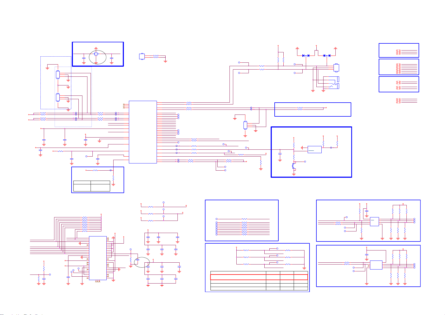
8.5 B 715G7776SSB
8-5-1 SOC-EMMC
DEBUG
CN1020
45
NC/CONN 3P
1
2
add text
3
CN1021
45
NC/CONN 3P
1
2
add text
3
SDA-SSB
SCL-SSB
2.2K 1/16W
SDA-SET
SCL-SET
2.2K 1/16W
I2C-signals double space
where possible GND shield
C9402
10UF 6.3V
+3V3-STAN DBY
R9466
2K7 1/16W 5%
C9403
10PF 50V
+3V3
+3V3
+3V3-STANDBY
C9405
10PF 50V
I2C-SSB
I2C-SET
R9411 2. 2K 1/ 16 W
R9405
R9414 2. 2K 1/ 16 W
R9416
Analog Power
+3V3-STANDBY
TP9441
TP9442
TP9443
TP9444
4.7UF 10V
+3V3-STANDBY
R9431: NA
R9432: Mount
XTAL I
24MHz CRYSTA L
1243
24MHz
C9400
10PF 50V
R9412 10OH M1/16W
R9413 10OH M1/16W
R9415
R9417 10OH M1/16W
+3V3-STAN DBY
C9404
10PF 50V
TP9434
R9431 4. 7K 1/ 16W
POR
External ResetInternal POR
R9431: Mount
R9432: NA
X9400
C9401
10PF 50V
7/27
10OHM1/16W
C9408
4.7UF 10V
NC/0R 05 OH M
XTAL I
XTAL O
+V-EMMC-I O
R9432
POR-SELECT
TP9445
XTAL O
TP9475
TP9476
TP9477
TP9478
U9400-7
U33
V33
V34
AT37
AT38
AN38
AN37
E37
E38
AA36
AJ38
U38
M25
Y36
V36
V37
U34
MT5593UGIJ
MT5593U+ HEAT SINK
CN9400
R9486
HEAT SINK
NC/0R 05 OH M
1
2
R9487
NC/0R 05 OH M
AE36
U0TX
AE37
POWE__B
POOE__B
POCE1__B
POCE0__B
PDD7
PDD6
PDD5
PDD4
PDD3
PDD2
PDD1
PDD0
PARB__B
PACLE
PAALE
EMMC_CLK
EMMC_RSTB
OPWRSB
ORESETB
FSRC_WR
STB_SCL
STB_SDA
U0RX
U1TX
U1RX
AM38
AM37
AG38
AH37
AF36
AF38
AJ33
AJ34
AJ35
AH34
AH32
AF32
AF33
AJ37
AH36
AG37
AE34
AL37
AK36
AJ32
DS
AB38
M34
Y35
OIRI
G20
AC37
AC38
CPC0
CPC1
CPC2
OSDA0
OSCL0
OSDA1
OSCL1
XTAL I
XTAL O
AVDD33_REG_STB
VCC3IO_EMMC
AVDD33_RGB_STB
AVSS33_RGB
AVDD33_PLL_STB
AVDD10_LDO
AVDD10_ELDO
POR_OPT
EMMC- CMD
EMMC- D7
EMMC- D6
EMMC- D5
EMMC- D4
EMMC- D3
EMMC- D2
EMMC- D1
EMMC- D0
EMMC- CLK
DS
TP9465
TP9464
R9406 1 0OHM1/16W
R9407 1 0OHM1/16W
R9408 1 0OHM1/16W
R9404 1 0OHM1/16W
TP9400
TP9401
TP9402
TP9403
TP9404
TP9405
R9474 22 OH M 1/16W
R9472 0R 05 OH M
TP9406
TP9472
R9421 10OHM1/16W
R9422 10OHM1/16W
TP9473
R9424 10OHM1/16W
TP9474
R9426 10 OHM1/16W
R9428 10 OHM1/16W
SOC-TX-SERVICE
SOC-RX-SERVICE
SOC-TX-BO
SOC-RX-BO
E2MC-CLK
STANDBY
SOC-RESET-INn
RC-IR
SCL-BE
SDA-BE
TP9435
TP9436
R9427 2.2K 1/16WC9407
R9429 2.2K 1/16W
TP9447
TP9446
TP9437
SOC-TX-SERVICE
SOC-RX-SERVICE
TP9438
45
EMMC-RESETn
R9445 NC/10K+-5%1 /16W
R9402 100OHM1/16W
R9403 100OHM1/16W
TP9439
TP9440
CN1011
NC/CONN 3P
1
2
3
TP9433
+3V3-STANDBY
+3V3-STANDBY
R9430
4.7K 1/16W
+3V3-STANDBY
R9400
R9401
4.7K 1/16W
4.7K 1/16W
R9409 4 . 7K 1/ 16W
R9410 4 . 7K 1/ 16W
TP9462
TP9463
BO serial interface
Reset IC
+3V3-STANDBY
R9418
10K+-5%1/16W
C9406
100NF 16V
R9425
NC/100 OHM1/16W
SW9400
NC/SW
D9402
LBAV99WT1G
132
1
2
TP9480
+3V3-STAN DBY
U9401
GND
RESET(RESET)
RT9818C-29GVL
LBAV99WT1G
2
+3V3-STANDBY
3
VDD
D9403
3
5
4
3
2
1
NC/PHONE JACK 4P
+3V3
R9419
0R05 OHM
1
1
2
3
TP9479
CN1300
CONN
CN1010
+3V3
R9420
NC/0R05 OHM
STRAPPING from SOC
LED-PWM119
LED-PWM019
LED-PWM219
SOC I2C
SCL-BE8
SDA-BE8
SCL-SSB17,18
SDA-SSB17, 18
SCL-SET23
SDA-SET23
SOC UART
SOC-TX-SERVICE25
SOC-RX-SERVICE25
SOC-TX-BO18
SOC-RX-BO18
RC-IR18, 23,25
EEPROM-WP19
STANDBY15
LED-PWM1
LED-PWM0
LED-PWM2
SCL-BE
SDA-BE
SCL-SSB
SDA-SSB
SCL-SET
SDA-SET
SOC-TX-SERVICE
SOC-RX-SERVICE
SOC-TX-BO
SOC-RX-BO
RC-IR
EEPROM-WP
STANDBY
EMMC
E2MC-CMD
E2MC-D2
E2MC-D3
E2MC-D4
E2MC-D5
E2MC-D6
E2MC-D7
EMMC-RESETn
R9434
NC/10K+-5%1 /16W
16GB
+V-E MMC-I O
R9471
4.7K 1/16W
C9419
NC/10U F 6.3V X5R +-20%
TP9421
+V-EMMC-I O
+3V3-EMMC
E2MC-D0
E2MC-D1
TP9432
TP9417
C9423
1uF 10V
EMMC VCC/VCCQ Power
R9440 N C/10K+-5%1/ 16W
R9441 N C/10K+-5%1/ 16W
R9442 N C/10K+-5%1/ 16W
R9443 N C/10K+-5%1/ 16W
R9447 N C/10K+-5%1/ 16W
R9448 N C/10K+-5%1/ 16W
R9450 N C/10K+-5%1/ 16W
R9453 N C/10K+-5%1/ 16W
R9456 N C/10K+-5%1/ 16W
TP9416
+V-EMMC-I O
A3
DAT0
A4
DAT1
A5
DAT2
A6
VSS
A7
NC
B2
DAT3
B3
DAT4
B4
DAT5
B5
DAT6
B6
DAT7
C2
VDDI
C4
Vssq
C5
NC
C6
Vccq
D4
A1 index
E5
NC
E6
Vcc
E7
Vss
E8
NC
E9
NC
E10
NC
F5
Vcc
F10
NC
G3
NC
NCB1NCC1NC
N1
U9403
P10
NC
P7
NC
P6
Vssq
P5
Vccq
P4
Vssq
P3
Vccq
N5
Vssq
N4
Vccq
N2
Vssq
M6
CLK
M5
CMD
M4
Vccq
K10
NC
K9
Vcc
K8
Vss
K7
NC
K6
NC
K5
RSTN
J5
VSS
J10
Vcc
H10
Vss
H5
DS
G10
NC
G5
Vss
THGBMBG6D1KBAIL
+3V3- EMMC
+V-E MMC-I O
E2MC-CLK
E2MC -CMD
NC/10K+-5%1/16W
EMMC-RESETn
R9468
TP9418
+3V3
R9444 0R 05 OH M
+3V3
R9433 N C / 0R 05 OH M
+1V8-EMMC-IO
R9435 0R 05 OH M
+3V3- EMMC
C9424
NC/10PF 50V
10UF 6.3V X5R +-20%
C9410
100NF 16V
C9413
100NF 16V
+V-EMMC-IO
C9416
C9420
1uF 10V
TP9419
+3V3-EMMC
TP9420
TP9422
C9411
10UF 6.3V X5R +-20%
C9414
100NF 16V
C9417
10UF 6.3V X5R +-20%
C9421
100NF 16V
+3V3- EMMC
+V-E MMC-I O
C9412
10UF 6.3V X5R +-20%
C9415
100NF 16V
C9418
10UF 6.3V X5R +-20%
C9422
100NF 16V
Place resistors close to eMMC
TP9407
TP9408
TP9409
TP9410
TP9411
TP9412
TP9413
TP9414
TP9415
STRAPPING
resistors close to each other
and in logical way
ICE moce + 24M + ROM to eMMC boot from
eMMC pins (share pins w/s NAND)
ICE mode + 24M + serial boot
ICE moce + 24M + ROM to 60bit ECC Nand boot
ICE mode + 24M + serial boot(with GPIO)
E2MC-D0
E2MC-D1
E2MC-D2
E2MC-D3
E2MC-D4
E2MC-D5
E2MC-D6
E2MC-D7
R9446 22 OHM 1/16W
R9449 22 OHM 1/16W
R9451 22 OHM 1/16W
R9454 22 OHM 1/16W
R9457 22 OHM 1/16W
R9458 22 OHM 1/16W
R9459 22 OHM 1/16W
R9460 22 OHM 1/16W
R9465 22 OHM 1/16W
+3V3-STANDBY
R9475 N C / 4.7K 1/1 6W
R9476 N C / 4.7K 1/1 6W
R9477 N C / 4.7K 1/1 6W
EMMC- CMDE2MC-CMD
EMMC-D0
EMMC-D1
EMMC-D2
EMMC-D3
EMMC-D4
EMMC-D5
EMMC-D6
EMMC-D7
TP9455
LED-PWM0
TP9456
LED-PWM1
TP9457
LED-PWM2
LED-PWM0STRAPPING LED-PWM2LED-PWM1
0
0
0
R9467 10K+-5%1/16W
R9470 10K+-5%1/16W
R9473 10K+-5%1/16W
0
1
10
+3V3
SYSTEM EEPROM
+3V3
EEPROM-WP
SCL-SSB
R9452 N C /47 OHM 1/ 16W
SDA-SSB
R9455 N C /47 OHM 1/ 16W
TP9454
TP9458
TP9459
NC/10K+-5%1/ 16W
R9461
R9436
TEMPERATURE SENSOR
SDA-SSB
SCL-SSB
00
1
0
1
R9478 NC/47 OH M 1/16W
R9479 NC/47 OH M 1/16W
TP9461
TP9460
8
7
6
5
NC/M24128-BR DW6TP
NC/10K+-5%1 /16W
+3V3
1
2
3
I2C ADDRESS "0xA0"
C9409
NC/0.22UF
U9402
1
E0
VCC
2
E1
WC
3
E2
SCL
VSS4SDA
I2C ADDRESS "0x98"
C9444
NC/0.22UF
U9415
8
SDA
V+
7
SCL
A0
6
ALERT
A1
5
GND4A2
NC/TMP75AID GKR
+3V3
R9437
R9438
R9439
NC/10OH M1/16W
NC/10OH M1/16W
NC/10OH M1/16W
TP9448
TP9449
TP9450
R9463
R9464
R9462
NC/10OH M1/16W
NC/10OH M1/16W
NC/10OH M1/16W
+3V3
R9480
R9481
R9482
10OHM1/16 W
NC/10OH M1/16W
NC/10OH M1/16W
R9483
NC/10O HM1/16W
TP9452
TP9453
TP9451
R9484
R9485
NC/10O HM1/16W
NC/10O HM1/16W
Page 55

8-5-2 SOC-DDR3-1-2
R9100
R9101
47 OHM 1/16W
47 OHM 1/16W
R9102
NC/49.9 OHM 1% 1/16W
+VREF-A 1-DQ
+VREF-A 2-DQ
TP9100
TP9101
R9103
NC/49.9 OHM 1% 1/16W
M0-MA0
M0-MA1
M0-MA2
M0-MA3
M0-MA4
M0-MA5
M0-MA6
M0-MA7
M0-MA8
M0-MA9
M0-MA10
M0-MA11
M0-MA12
M0-MA13
M0-MA14
M0-BA0
M0-BA1
M0-BA2
M0-CSn
M0-CSD n
M0-RAS n
M0-CAS n
M0-WEn
M0-ODT
M0-CKE
M0-RESETn
M0-MCLK 0p
M0-MCLK 0n
M0-RTp
M0-RTn
M0-MEMTp
M0-MEMTn
TP-HPCPLL
TN-H PCPL L
+1V5-DD R
U9400-1
AE4
AG6
AF7
AF4
AG5
AG7
AH4
AD7
AK6
AF6
AK5
AM4
AD5
AE3
AD6
AB5
AB4
AA5
AA6
AB7
AB6
AA7
AK4
Y10
W10
AE10
AF10
AK19
AK18
AB8
AC10
AC9
AD10
AH10
AH9
AJ10
AJ11
AK10
AK11
AJ6
AJ5
AL4
Y4
Y5
V1
AJ2
AJ8
AJ9
Y6
ARA0
ARA1
ARA2
ARA3
ARA4
ARA5
ARA6
ARA7
ARA8
ARA9
ARA10
ARA11
ARA12
ARA13
ARA14
ARBA0
ARBA1
ARBA2
ARCS#
ARCSD#
ARRAS#
ARCAS#
ARWE#
ARODT
ARCKE
ARRESET#
ARCLK0
ARCLK0#
DDRVREF_A1
DDRVREF_A2
ARTP
ARTN
MEMTP
MEMTN
TP_HPCPLL
TN_H PC PLL
DDRV
DDRV
DDRV
DDRV
DDRV
DDRV
DDRV
DDRV
DDRV
DDRV
DDRV
DDRV
DDRV_CKA
MT5593UGIJ
ARDQM0
ARDQS0
ARDQS0#
ARDQ0
ARDQ1
ARDQ2
ARDQ3
ARDQ4
ARDQ5
ARDQ6
ARDQ7
ARDQM1
ARDQS1
ARDQS1#
ARDQ8
ARDQ9
ARDQ10
ARDQ11
ARDQ12
ARDQ13
ARDQ14
ARDQ15
ARDQM2
ARDQS2
ARDQS2#
ARDQ16
ARDQ17
ARDQ18
ARDQ19
ARDQ20
ARDQ21
ARDQ22
ARDQ23
ARDQM3
ARDQS3
ARDQS3#
ARDQ24
ARDQ25
ARDQ26
ARDQ27
ARDQ28
ARDQ29
ARDQ30
ARDQ31
AVDD33_DDR
AVDD10_DDR
AVDD10_DDR
AVDD10_DDR
AVSS_DDR
AVSS_DDR
AVSS_DDR
AVSS_DDR
AD1
AC1
AC2
Y2
AG2
Y1
AG3
W1
AH3
W2
AH2
AC3
AD2
AE2
AF1
AB3
AG1
Y3
AF2
AB2
AF3
AB1
AN2
AM3
AN1
AK2
AT2
AK1
AU1
AJ1
AU2
AJ3
AR4
AM1
AP1
AP2
AR2
AL2
AT1
AK3
AP3
AL3
AR3
AM2
G1
AV20
AF13
AE19
G2
AU20
AF12
AE17
M0-D QM0
M0-D QS0p
M0-D QS0n
M0-MD 0
M0-MD 1
M0-MD 2
M0-MD 3
M0-MD 4
M0-MD 5
M0-MD 6
M0-MD 7
M0-D QM1
M0-D QS1p
M0-D QS1n
M0-MD 8
M0-MD 9
M0-MD 10
M0-MD 11
M0-MD 12
M0-MD 13
M0-MD 14
M0-MD 15
M0-D QM2
M0-D QS2p
M0-D QS2n
M0-MD 16
M0-MD 17
M0-MD 18
M0-MD 19
M0-MD 20
M0-MD 21
M0-MD 22
M0-MD 23
M0-D QM3
M0-D QS3p
M0-D QS3n
M0-MD 24
M0-MD 25
M0-MD 26
M0-MD 27
M0-MD 28
M0-MD 29
M0-MD 30
M0-MD 31
GND-3V3-DDR
GND-1V0-DDR
GND-1V0-DDR
GND-1V0-DDR
MT5593 DDR 32b #1
+3V3-D DR
+1V0-D DR
+1V0-D DR
+1V0-D DR
TP9171
TP9172
TP9178
TP9179
TP9180
TP9181
TP9182
TP9183
TP9184
TP9185
TP9186
TP9187
TP9188
TP9189
TP9190
TP9191
TP9193
TP9192
TP9194
TP9195
TP9196
TP9197
TP9198
VREF_DQ
VREF_CA
UDQS
UDQS
DQL0
DQL1
DQL2
DQL3
DQL4
DQL5
DQL6
DQL7
DQU0
DQU1
DQU2
DQU3
DQU4
DQU5
DQU6
DQU7
LDQS
LDQS
H9
LDM
UDM
ODT
G9
TP9115
U9101
K4B4G1646E-BCMA
H1
M8
E3
M0-MD0
F7
M0-MD1
F2
M0-MD2
F8
M0-MD3
H3
M0-MD4
H8
M0-MD5
G2
M0-MD6
H7
M0-MD7
D7
M0-MD8
C3
M0-MD9
C8
M0-MD10
C2
M0-MD11
A7
M0-MD12
A2
M0-MD13
B8
M0-MD14
A3
M0-MD15
F3
M0-D QS0p
G3
M0-D QS0n
C7
M0-D QS1p
B7
M0-D QS1n
E7
M0-D QM0
D3
M0-D QM1
K1
M0-ODT
C9191
100NF 16V
+VREF-A 1-DQ
+VREF-A 1-CA
1
1
1
1
1
1
1
1
1
1
1
1
1
1
1
1
1
1
1
1
1
1
1
TP9117
TP9118
TP9121
TP9120
TP9102
TP9103
TP9119
TP9126
TP9127
TP9124
TP9125
TP9128
TP9122
TP9123
TP9129
TP9130
TP9104
TP9105
TP9106
TP9107
TP9131
TP9132
TP9133
TP9153
TP9154
TP9156
TP9155
TP9160
TP9157
TP9159
TP9158
TP9164
TP9161
TP9163
TP9162
TP9168
TP9165
TP9167
TP9170
TP9166
TP9169
TP9173
TP9174
TP9177
TP9175
TP9176
+1V5-DDR
M0-MA0
M0-MA1
M0-MA2
M0-MA3
M0-MA4
M0-MA5
M0-MA6
M0-MA7
M0-MA8
M0-MA9
M0-MA1 0
M0-MA1 1
M0-MA1 2
M0-MA1 3
M0-MA1 4
M0-BA0
M0-BA1
M0-BA2
M0-MC LK0p
M0-MC LK0n
M0-C KE
M0-C Sn
M0-RASn
M0-CASn
M0-W En
M0-RESETn
R9105
N3
A0
P7
A1
P3
A2
N2
A3
P8
A4
P2
A5
R8
A6
R2
A7
T8
A8
R3
A9
L7
A10/AP
R7
A11
N7
A12/BC
T3
A13
T7
A14
M7
NC_A15
M2
BA0
N8
BA1
M3
BA2
J7
CK
K7
CK
K9
CKE
L2
CS
J3
RAS
K3
CAS
L3
WE
T2
RST
L8
ZQ
240 OHM +-1% 1/16W
1
1
1
1
1
1
1
1
1
1
1
1
1
1
1
1
1
1
1
1
1
1
1
R9
VDDB2VDDD9VDDG7VDDK2VDDK8VDDN1VDDN9VDDR1VDD
VSSA9VSSB3VSSE1VSSG8VSSJ2VSSJ8VSSM1VSSM9VSSP1VSSP9VSST1VSST9VSSQB1VSSQB9VSSQD1VSSQD8VSSQE2VSSQE8VSSQF9VSSQG1VSSQ
VDDQA1VDDQA8VDDQC1VDDQC9VDDQD2VDDQE9VDDQF1VDDQH2VDDQ
+1V5-DDR
M0-MA0
M0-MA1
M0-MA2
M0-MA3
M0-MA4
M0-MA5
M0-MA6
M0-MA7
M0-MA8
M0-MA9
M0-MA1 0
M0-MA1 1
M0-MA1 2
M0-MA1 3
M0-MA1 4
M0-MC LK0p
M0-MC LK0n
M0-RESETn
R9104
N3
A0
P7
A1
P3
A2
N2
A3
P8
A4
P2
A5
R8
A6
R2
A7
T8
A8
R3
A9
L7
A10/AP
R7
A11
N7
A12/BC
T3
A13
T7
A14
M7
NC_A15
M2
BA0
N8
BA1
M3
BA2
J7
CK
K7
CK
K9
CKE
L2
CS
J3
RAS
K3
CAS
L3
WE
T2
RST
L8
ZQ
240 OHM +-1% 1/16W
1
1
1
1
1
1
1
1
1
1
1
1
1
1
1
1
M0-BA 0
1
M0-BA 1
1
M0-BA 2
1
M0-C KE
1
M0-C Sn
1
M0-RASn
1
M0-CASn
1
M0-W En
R9
VDDB2VDDD9VDDG7VDDK2VDDK8VDDN1VDDN9VDDR1VDD
VSSA9VSSB3VSSE1VSSG8VSSJ2VSSJ8VSSM1VSSM9VSSP1VSSP9VSST1VSST9VSSQB1VSSQB9VSSQD1VSSQD8VSSQE2VSSQE8VSSQF9VSSQG1VSSQ
VDDQA1VDDQA8VDDQC1VDDQC9VDDQD2VDDQE9VDDQF1VDDQH2VDDQ
DDR3#1
VREF_DQ
VREF_CA
DQU0
DQU1
DQU2
DQU3
DQU4
DQU5
DQU6
DQU7
LDQS
LDQS
UDQS
UDQS
H9
DQL0
DQL1
DQL2
DQL3
DQL4
DQL5
DQL6
DQL7
LDM
UDM
ODT
G9
TP9116
U9102
K4B4G1646E-BCMA
H1
M8
E3
M0-MD 16
F7
M0-MD 17
F2
M0-MD 18
F8
M0-MD 19
H3
M0-MD 20
H8
M0-MD 21
G2
M0-MD 22
H7
M0-MD 23
D7
M0-MD 24
C3
M0-MD 25
C8
M0-MD 26
C2
M0-MD 27
A7
M0-MD 28
A2
M0-MD 29
B8
M0-MD 30
A3
M0-MD 31
F3
M0-D QS2p
G3
M0-D QS2n
C7
M0-D QS3p
B7
M0-D QS3n
E7
M0-D QM2
D3
M0-D QM3
K1
M0-ODT
C9192
100NF 16V
+VREF-A 2-DQ
+VREF-A 2-CA
1
1
1
1
1
1
1
1
1
1
1
1
1
1
1
1
1
1
1
1
1
1
1
DDR3#2
TP9147
TP9148
TP9145
TP9146
TP9149
TP9134
TP9135
TP9140
TP9141
TP9137
TP9139
TP9142
TP9136
TP9138
TP9143
TP9144
TP9108
TP9109
TP9110
TP9111
TP9150
TP9151
TP9152
+1V5-DDR
+1V5-DDR
C9164
C9153
100NF 16V
100NF 16V
R9110
0R05 OHM
GND-3V3-DDR
C9135
100NF 16V
C9178
100NF 16V
+3V3-DD R
C9137
100NF 16V
C9179
100NF 16V
C9177
1UF16V
C9140
100NF 16V
C9182
100NF 16V
DDR3#2 Ref Volt.
R9108
R9113
TP9114
R9117
NC/0R05 OHM
NC/0R05 OHM
+1V5-DDR
Near DRAM
C9163
100NF 16V
C9151
100NF 16V
+VREF -A1-C A
+VREF -A2-C A
+VREF-A 1-CA
+VREF -A1-D Q
+VREF -A2-D Q
+1V0-VCC K+3V3
R9111
0R05 OHM
GND-1V0-DDR
C9138
C9139
100NF 16V
100NF 16V
C9141
C9142
C9146
100NF 16V
100NF 16V
100NF 16V
C9166
1UF16V
C9143
C9144
C9145
100NF 16V
100NF 16V
100NF 16V
+1V0-VCCK+1V0-DDR +1V0-DDR
C9147
C9148
C9155
100NF 16V
100NF 16V
100NF 16V
R9112
NC/0R05 OHM
GND-1V0-DDR
C9149
C9150
C9154
100NF 16V
100NF 16V
100NF 16V
C9136
NC/1UF16V
10UF
C9162
C9175
C9176
1uF 10V
1uF 10V
DDR3#1 Ref Volt.
1KOHM +-1% 1/16W
1KOHM +-1% 1/16W
DRAM Decoupling: Place close to DRAM#1
1KOHM +-1% 1/16W
1KOHM +-1% 1/16W
PU/PD resistors
R9107
TP9113R9119
R9109
M0-RESETn
M0-C Sn
M0-C SDn
M0-C KE
+1V5-D DR
Near DRAM
R9114
NC/4. 7K 1/16W
C9190
22NF 25V
R9115
47 OHM 1/16W
R9116
47 OHM 1/16W
R9118
NC/4.7K 1/16W
C9161
100NF 16V
C9159
100NF 16V
+VREF-A2 -CA
+1V5-DDR
C9129
100NF 16V
Differential Clock
C9167
C9169
C9170
C9180
C9181
100NF 16V
100NF 16V
C9183
C9184
C9188
100NF 16V
C9187
100NF 16V
100NF 16V
100NF 16V
C9165
C9185
C9186
100NF 16V
100NF 16V
100NF 16V
C9168
C9189
100NF 16V
100NF 16V
100NF 16V
100NF 16V
100NF 16V
+
C9171
C9172
C9173
1uF 10V
1uF 10V
100UF 16V
DRAM Decoupling: Place close to DRAM#2
C9174 10UF
NEAR Main Chip
M0-MCLK 0p
M0-MCLK 0n
Close to DRAM
M0-MC LK0p
R9120
100R 1/16W 1%
M0-MC LK0n
Page 56

8-5-3 SOC-DDR3-3-4
+1V5-DDR
+1V5-DDR
U9400-2
AR12
+VREF -B1- DQ
+VREF -B2- DQ
47 OHM 1/ 16W
R9201
R9200
M1-MA0
M1-MA1
M1-MA2
M1-MA3
M1-MA4
M1-MA5
M1-MA6
M1-MA7
M1-MA8
M1-MA9
M1-MA10
M1-MA11
M1-MA12
M1-MA13
M1-MA14
M1-BA0
M1-BA1
M1-BA2
M1-C Sn
M1-C SDn
M1-R ASn
M1-C ASn
M1-W En
M1-OD T
M1-C KE
M1-RESETn
M1-MC LK0p
M1-MC LK0n
M1-R Tp
M1-R Tn
+1V5-DD R
47 OHM 1/ 16W
AP15
AN14
AP13
AR15
AP14
AN17
AN16
AP18
AP16
AN10
AP17
AR13
AR17
AN18
AP11
AN13
AP12
AR10
AP10
AR18
AV11
AL18
AL19
AK12
AK13
AK14
AK15
AK16
AK17
AR9
AR7
AP7
AP9
AN9
AP6
AR6
AV2
AL9
AK7
AK8
AK9
AL6
AL7
AL8
AM8
BRA0
BRA1
BRA2
BRA3
BRA4
BRA5
BRA6
BRA7
BRA8
BRA9
BRA10
BRA11
BRA12
BRA13
BRA14
BRBA0
BRBA1
BRBA2
BRCS#
BRCSD#
BRRAS#
BRCAS#
BRWE#
BRODT
BRCKE
BRRESET#
BRCLK0
BRCLK0#
DDRVREF_B1
DDRVREF_B2
BRTP
BRTN
DDRV
DDRV
DDRV
DDRV
DDRV
DDRV
DDRV
DDRV
DDRV
DDRV
DDRV
DDRV
DDRV
DDRV_CKB
MT5593UGIJ
+1V5-DDR
Provision
C9224
C9225
C9227
C9228
C9223
100NF 16V
C9246
C9247
100NF 16V
100NF 16V
C9226
100NF 16V
100NF 16V
C9248
100NF 16V
100NF 16V
100NF 16V
C9250
C9249
C9251
100NF 16V
100NF 16V
100NF 16V
C9230
C9229
100NF 16V
100NF 16V
100NF 16V
C9253
C9254
C9252
100NF 16V
100NF 16V
AU7
BRDQ0
BRDQ1
BRDQ2
BRDQ3
BRDQ4
BRDQ5
BRDQ6
BRDQ7
BRDQ8
BRDQ9
M1-D QM0
AU6
M1-D QS0p
AT6
M1-D QS0n
AU4
M1-MD 0
AT10
M1-MD 1
AU3
M1-MD 2
AU10
M1-MD 3
AT3
M1-MD 4
AU11
M1-MD 5
AV3
M1-MD 6
AT11
M1-MD 7
AV6
M1-D QM1
AT8
M1-D QS1p
AU8
M1-D QS1n
AT9
M1-MD 8
AU5
M1-MD 9
AU9
M1-MD 10
AR5
M1-MD 11
AV8
M1-MD 12
AV5
M1-MD 13
AV9
M1-MD 14
AT5
M1-MD 15
AT15
M1-D QM2
AV15
M1-D QS2p
AU15
M1-D QS2n
AT13
M1-MD 16
AU18
M1-MD 17
AU12
M1-MD 18
AT18
M1-MD 19
AT12
M1-MD 20
AT19
M1-MD 21
AV12
M1-MD 22
AU19
M1-MD 23
AR14
M1-D QM3
AU16
M1-D QS3p
AT16
M1-D QS3n
AV17
M1-MD 24
AT14
M1-MD 25
AV18
M1-MD 26
AU13
M1-MD 27
AU17
M1-MD 28
AU14
M1-MD 29
AT17
M1-MD 30
AV14
M1-MD 31
C9280
C9281
C9273
NC/ 1uF 10V
NC/10UF 6. 3V X5R +-20%
C9234
C9233
C9232
100NF 16V
100NF 16V
NC/100N16V
C9236
C9235
100NF 16V
100NF 16V
100NF 16V
TP9276
TP9277
TP9279
TP9278
TP9281
TP9280
TP9282
TP9283
TP9284
TP9285
TP9286
TP9287
TP9289
TP9288
TP9290
TP9292
TP9291
TP9293
TP9296
TP9297
TP9299
TP9298
TP9294
C9274
C9275
NC/100N16V
NC/100N16V
C9237
C9239
C9238
100NF 16V
100NF 16V
100NF 16V
C9231
BRDQM0
BRDQS0
BRDQS0#
BRDQM1
BRDQS1
BRDQS1#
BRDQ10
BRDQ11
BRDQ12
BRDQ13
BRDQ14
BRDQ15
BRDQM2
BRDQS2
BRDQS2#
BRDQ16
BRDQ17
BRDQ18
BRDQ19
BRDQ20
BRDQ21
BRDQ22
BRDQ23
BRDQM3
BRDQS3
BRDQS3#
BRDQ24
BRDQ25
BRDQ26
BRDQ27
BRDQ28
BRDQ29
BRDQ30
BRDQ31
100NF 16V
DRAM Decoupling: Place near DRAM#3
C9262
C9260
C9261
C9255
100NF 16V
100NF 16V
100NF 16V
C9259
100NF 16V
100NF 16V
100NF 16V
100NF 16V
C9258
C9256
C9257
C9263
100NF 16V
100NF 16V
+1V5-D DR
1
M1-MA0
1
M1-MA1
1
M1-MA2
1
M1-MA3
1
M1-MA4
1
M1-MA5
1
M1-MA6
1
M1-MA7
1
M1-MA8
1
M1-MA9
1
M1-MA10
1
M1-MA11
1
M1-MA12
1
M1-MA13
1
M1-MA14
1
M1-BA0
1
M1-BA1
1
M1-BA2
M1-MCLK0p
M1-MCLK0n
1
M1-C KE
1
M1-C Sn
1
M1-R ASn
1
M1-C ASn
1
M1-W En
M1-RESETn
C9276
C9277
NC/100N16V
NC/100N16V
C9240
C9241
100NF 16V
C9264
1uF 10V
100NF 16V
N3
A0
P7
A1
P3
A2
N2
A3
P8
A4
P2
A5
R8
A6
R2
A7
T8
A8
R3
A9
L7
A10/AP
R7
A11
N7
A12/BC
T3
A13
T7
A14
M7
NC_A15
M2
BA0
N8
BA1
M3
BA2
J7
CK
K7
CK
K9
CKE
L2
CS
J3
RAS
K3
CAS
L3
WE
T2
RST
L8
ZQ
R9202
240 OHM +-1% 1/ 16 W
C9278
C9242
1uF 10V
C9265
1uF 10V
VSSA9VSSB3VSSE1VSSG8VSSJ2VSSJ8VSSM1VSSM9VSSP1VSSP9VSST1VSST9VSSQB1VSSQB9VSSQD1VSSQD8VSSQE2VSSQE8VSSQF9VSSQG1VSSQ
C9279
NC/100N16V
NC/100N16V
C9243
10UF
1uF 10V
C9267
+
C9266
10UF
100UF 16V
R9
VDDB2VDDD9VDDG7VDDK2VDDK8VDDN1VDDN9VDDR1VDD
VDDQA1VDDQA8VDDQC1VDDQC9VDDQD2VDDQE9VDDQF1VDDQH2VDDQ
+VREF-B1-DQ
+VREF-B2-DQ
DDR3#3 Ref Volt. DDR3#4 Ref Volt.
R9218
1KOHM +-1% 1/16W
TP9210TP
R9217
1KOHM +-1% 1/16W
VREF_DQ
VREF_CA
+1V5-D DR
TP9211
TP
U9201
K4B4G1646E-BCMA
H9
DQL0
DQL1
DQL2
DQL3
DQL4
DQL5
DQL6
DQL7
DQU0
DQU1
DQU2
DQU3
DQU4
DQU5
DQU6
DQU7
LDQS
LDQS
UDQS
UDQS
LDM
UDM
ODT
G9
R9219
NC/0R05 OHM
R9220
NC/0R05 OHM
H1
M8
E3
F7
F2
F8
H3
H8
G2
H7
D7
C3
C8
C2
A7
A2
B8
A3
F3
G3
C7
B7
E7
D3
K1
C9244
100NF 16V
C9268
100NF 16V
C9269
100NF 16V
M1-MD 0
M1-MD 1
M1-MD 2
M1-MD 3
M1-MD 4
M1-MD 5
M1-MD 6
M1-MD 7
M1-MD 8
M1-MD 9
M1-MD 10
M1-MD 11
M1-MD 12
M1-MD 13
M1-MD 14
M1-MD 15
M1-D QS0p
M1-D QS0n
M1-D QS1p
M1-D QS1n
M1-D QM0
M1-D QM1
M1-OD T
DDR3#3MT5593 DDR 32b #2
+VREF-B1-CA
+VREF-B2-CA
+VREF-B1-CA
+VREF -B1- DQ
+VREF -B1- CA
1
1
1
1
1
1
1
1
1
1
1
1
1
1
1
1
1
1
1
1
1
1
1
N3
P7
P3
N2
P8
P2
R8
R2
T8
R3
L7
R7
N7
T3
T7
M7
M2
N8
M3
J7
K7
K9
L2
J3
K3
L3
T2
L8
R9203
240 OHM +-1% 1/ 16 W
TP921 3
TP921 4
TP921 5
TP921 6
TP921 7
TP921 8
TP921 9
TP922 0
TP922 2
TP922 1
TP922 3
TP922 4
TP922 5
TP922 6
TP922 7
TP922 8
TP920 0
TP920 1
TP920 2
TP920 3
TP922 9
TP923 0
TP923 1
TP9251
TP9252
TP9254
TP9253
TP9256
TP9255
TP9257
TP9258
TP9259
TP9260
TP9261
TP9262
TP9264
TP9263
TP9265
TP9267
TP9266
TP9268
TP9269
TP9270
TP9271
TP9272
TP9274
TP9273
TP9275
1
1
1
1
1
1
1
1
1
1
1
1
1
1
1
1
1
1
1
1
1
1
1
1
1
M1-MA0
M1-MA1
M1-MA2
M1-MA3
M1-MA4
M1-MA5
M1-MA6
M1-MA7
M1-MA8
M1-MA9
M1-MA10
M1-MA11
M1-MA12
M1-MA13
M1-MA14
M1-BA0
M1-BA1
M1-BA2
M1-MC LK0p
M1-MC LK0n
M1-C KE
M1-C Sn
M1-R ASn
M1-C ASn
M1-W En
M1-RESETn
Damping and Termination
for CLK
Close to MainChip
M1-MC LK0p
M1-MC LK0n
+1V5-DDR
R9215
1KOHM +-1% 1/16W
TP9209TP
R9216
1KOHM +-1% 1/16W
Close to DRAM
M1-MC LK0p
R9209
100R 1/16W 1%
M1-MC LK0n
C9245
100NF 16V
+VREF-B2-CA
C9270
100NF 16V
+1V5-DDR
R9
A0
VDDB2VDDD9VDDG7VDDK2VDDK8VDDN1VDDN9VDDR1VDD
A1
A2
A3
A4
A5
A6
A7
A8
A9
A10/AP
A11
A12/BC
A13
A14
NC_A15
BA0
BA1
BA2
CK
CK
CKE
CS
RAS
CAS
WE
RST
ZQ
VSSA9VSSB3VSSE1VSSG8VSSJ2VSSJ8VSSM1VSSM9VSSP1VSSP9VSST1VSST9VSSQB1VSSQB9VSSQD1VSSQD8VSSQE2VSSQE8VSSQF9VSSQG1VSSQ
VDDQA1VDDQA8VDDQC1VDDQC9VDDQD2VDDQE9VDDQF1VDDQH2VDDQ
VREF_DQ
VREF_C A
DQU0
DQU1
DQU2
DQU3
DQU4
DQU5
DQU6
DQU7
LDQS
LDQS
UDQS
UDQS
PU/PD resistors
M1-RESETn
M1-C Sn
M1-C SDn
M1-C KE
TP9212
TP
U9202
K4B4G1646E-BCMA
H9
DQL0
DQL1
DQL2
DQL3
DQL4
DQL5
DQL6
DQL7
LDM
UDM
ODT
G9
R9212
NC/4.7K 1/ 16W
H1
M8
E3
M1-MD16
F7
M1-MD17
F2
M1-MD18
F8
M1-MD19
H3
M1-MD20
H8
M1-MD21
G2
M1-MD22
H7
M1-MD23
D7
M1-MD24
C3
M1-MD25
C8
M1-MD26
C2
M1-MD27
A7
M1-MD28
A2
M1-MD29
B8
M1-MD30
A3
M1-MD31
F3
M1-D QS2p
G3
M1-D QS2n
C7
M1-D QS3p
B7
M1-D QS3n
E7
M1-D QM2
D3
M1-D QM3
K1
M1-OD T
R9206
47 OHM 1/16W
R9213
47 OHM 1/16W
C9271
100NF 16V
DDR3#4
R9205
NC/4.7K 1/ 16W
C9272
22NF 25V
+VREF-B2-DQ
+VREF-B2-CA
1
1
1
1
1
1
1
1
1
1
1
1
1
1
1
1
1
1
1
1
1
1
1
TP9232
TP9233
TP9235
TP9234
TP9236
TP9237
TP9238
TP9239
TP9240
TP9241
TP9242
TP9243
TP9244
TP9245
TP9246
TP9247
TP9206
TP9207
TP9204
TP9205
TP9248
TP9249
TP9250
+1V5-DD R
C9220
100NF 16V
DRAM Decoupling: Place near DRAM#4
Near DRAMNear DRAM
Page 57

8-5-4 SOC-DDR3-5
+VREF -C1- DQ
R9301
R9300
47 OHM 1/16W
47 OHM 1/16W
+1V5-D DR
M2-MA0
M2-MA1
M2-MA2
M2-MA3
M2-MA4
M2-MA5
M2-MA6
M2-MA7
M2-MA8
M2-MA9
M2-MA10
M2-MA11
M2-MA12
M2-MA13
M2-MA14
M2-BA0
M2-BA1
M2-BA2
M2-CS n
M2-CS Dn
M2-RA Sn
M2-CA Sn
M2-WEn
M2-OD T
M2-CK E
M2-RESETn
M2-MCL K0p
M2-MCL K0n
M2-RTp
M2-RTn
U5
K7
U4
K8
U9
H7
U8
H8
U6
R4
H5
U7
K5
P7
P9
P8
H6
P4
P5
H1
G3
G4
U10
AM5
AM6
AM7
AN4
AN5
AN6
AP4
AP5
K10
L10
N10
T10
P10
J5
J4
T6
T4
L5
L6
L8
L7
T7
U9400-13
MT5593UGIJ
CRA0
CRA1
CRA2
CRA3
CRA4
CRA5
CRA6
CRA7
CRA8
CRA9
CRA10
CRA11
CRA12
CRA13
CRA14
CRBA0
CRBA1
CRBA2
CRCS#
CRCSD#
CRRAS#
CRCAS#
CRWE#
CRODT
CRCKE
CRRESET#
CRCLK0
CRCLK0#
DDRVREF_C1
CRTP
CRTN
DDRV
DDRV
DDRV
DDRV
DDRV
DDRV
DDRV
DDRV
DDRV
DDRV
DDRV
DDRV
DDRV
DDRV_CKC
CRDQM0
CRDQS0
CRDQS0#
CRDQ0
CRDQ1
CRDQ2
CRDQ3
CRDQ4
CRDQ5
CRDQ6
CRDQ7
CRDQM1
CRDQS1
CRDQS1#
CRDQ8
CRDQ9
CRDQ10
CRDQ11
CRDQ12
CRDQ13
CRDQ14
CRDQ15
N1
M2-D QM0
N3
M2-D QS0 p
N2
M2-D QS0 n
K2
M2-MD 0
T2
M2-MD 1
J2
M2-MD 2
U2
M2-MD 3
H2
M2-MD 4
V2
M2-MD 5
H3
M2-MD 6
U1
M2-MD 7
M3
M2-D QM1
P2
M2-D QS1 p
P1
M2-D QS1 n
R3
M2-MD 8
K3
M2-MD 9
R2
M2-MD 10
K1
M2-MD 11
P3
M2-MD 12
L1
M2-MD 13
R1
M2-MD 14
L2
M2-MD 15
TP9300
TP9301
TP9302
TP9303
TP9304
TP9305
TP9306
TP9307
TP9308
TP9309
TP9310
TP9311
TP9312
TP9313
TP9314
TP9315
TP9316
TP9317
TP9318
TP9319
TP9320
TP9322
TP9321
1
1
1
1
1
1
1
1
1
1
1
1
1
1
1
1
1
1
1
1
1
1
1
M2-MA0
M2-MA1
M2-MA2
M2-MA3
M2-MA4
M2-MA5
M2-MA6
M2-MA7
M2-MA8
M2-MA9
M2-MA10
M2-MA11
M2-MA12
M2-MA13
M2-MA14
M2-BA0
M2-BA1
M2-BA2
M2-MCL K0p
M2-MCL K0n
M2-C KE
M2-C Sn
M2-RASn
M2-CASn
M2-WEn
M2-RESETn
R9303
240 OHM +-1% 1/16W
+1V5-DDR
VDDB2VDDD9VDDG7VDDK2VDDK8VDDN1VDDN9VDDR1VDD
R9
VDDQA1VDDQA8VDDQC1VDDQC9VDDQD2VDDQE9VDDQF1VDDQH2VDDQ
N3
A0
P7
A1
P3
A2
N2
A3
P8
A4
P2
A5
R8
A6
R2
A7
T8
A8
R3
A9
L7
A10/AP
R7
A11
N7
A12/BC
T3
A13
T7
A14
M7
NC_A15
M2
BA0
N8
BA1
M3
BA2
J7
CK
K7
CK
K9
CKE
L2
CS
J3
RAS
K3
CAS
L3
WE
T2
RST
L8
ZQ
VSSA9VSSB3VSSE1VSSG8VSSJ2VSSJ8VSSM1VSSM9VSSP1VSSP9VSST1VSST9VSSQB1VSSQB9VSSQD1VSSQD8VSSQE2VSSQE8VSSQF9VSSQG1VSSQ
VREF_DQ
VREF_CA
DQL0
DQL1
DQL2
DQL3
DQL4
DQL5
DQL6
DQL7
DQU0
DQU1
DQU2
DQU3
DQU4
DQU5
DQU6
DQU7
LDQS
LDQS
UDQS
UDQS
TP9346
TP
U9301
K4B4G1646E-BCMA
H9
H1
M8
E3
F7
F2
F8
H3
H8
G2
H7
D7
C3
C8
C2
A7
A2
B8
A3
F3
G3
C7
B7
E7
LDM
D3
UDM
K1
ODT
G9
C9322
100NF 16V
M2-MD0
M2-MD1
M2-MD2
M2-MD3
M2-MD4
M2-MD5
M2-MD6
M2-MD7
M2-MD8
M2-MD9
M2-MD10
M2-MD11
M2-MD12
M2-MD13
M2-MD14
M2-MD15
M2-DQS0p
M2-DQS0n
M2-DQS1p
M2-DQS1n
M2-DQM0
M2-DQM1
M2-OD T
+VREF -C1- DQ
+VREF -C1- CA
1
1
1
1
1
1
1
1
1
1
1
1
1
1
1
1
1
1
1
1
1
1
1
TP9323
TP9324
TP9325
TP9326
TP9327
TP9328
TP9329
TP9330
TP9331
TP9332
TP9333
TP9334
TP9335
TP9336
TP9337
TP9338
TP9339
TP9340
TP9341
TP9342
TP9343
TP9344
TP9345
+1V5-D DR
MT5593 DDR 16b
DDR3#5
Differential Clock
C9301
C9302
C9300
100NF 16V
100NF 16V
C9304
C9303
100NF 16V
C9305
C9307
C9308
C9310
C9306
100NF 16V
100NF 16V
100NF 16V
100NF 16V
C9309
100NF 16V
100NF 16V
C9311
100NF 16V
100NF 16V
100NF 16V
C9313
C9312
100NF 16V
100NF 16V
C9316
C9314
C9315
C9317
100NF 16V
100NF 16V
100NF 16V
100NF 16V
DRAM Decoupling: Place close to DRAM#5
+
C9318
C9319
C9320
1uF 10V
1uF 10V
100UF 16V
C9321 10UF
+VREF -C1-DQ
DDR3#5 Ref Volt.
R9312
1KOHM +-1% 1/16W
TP9348
TP
R9310
1KOHM +-1% 1/16W
R9313
NC/0R05 OHM
+1V5-DDR
Near DRAM
C9344
100NF 16V
C9346
100NF 16V
+VREF -C1-CA
+VREF-C1-CA
Close to MainChip
M2-MCL K0p
M2-MCL K0n
PU/PD resistors
M2-RESETn
M2-C Sn
M2-C SDn
M2-C KE
C9348
22NF 25V
R9308
47 OHM 1/16W
R9309
47 OHM 1/16W
R9311
NC/4. 7K 1/16W
R9307
NC/4.7K 1/16W
Close to DRAM
M2-MCL K0p
R9304
100R 1/16W 1%
M2-MCL K0n
+1V5-DDR
C9345
100NF 16V
Page 58

8-5-5 FE-TUNER-DEMOD-TPV
TU201
1
8
Ant. PWR
TH1
9
TH2
2
GND_Tuner
10
+B1(+3.3V)
TH3
11
TH4
12
TH5
13
TH6
DIF(N)
IF AGC
DIF(P)
TUNER_3V3
3
TUNER_SDA
SDA
4
TUNER_SCL
SCL
5
IF_N_TU
6
IF_P_TU
7
IF_AGC_T
Tuner for DVB-C/T/T2
Tuner for DVB-S2
NC for PUT6401 models
TU202
12
1
TUNER_LNB
C222
GND_Tuner
1nF 50V
C212
C220
0.1uF 50V
GND_Tuner
GND_Tuner
GND_Tuner
CLK_IN_OUT
R245
NC/0R05 1/16W
R236
0R05 1/16W
R227
4K7 1/16W 5%
RF_AGC_S2_TUNER IF_AGC_S2 _TUNER
GND_Tuner
GND_Tuner
TH1
LNB A
13
TH2
14
2
TH3
NC
15
TH4
3
+3V3_S2_TUNER
TU3.3 V
4
NC
5
6
7
8
RF_AGC_S2_TUNER
9
X-OU T
10
S2_SDA
11
S2_SCL
EXT IF AGC
TUNER
IF_AGC_T
GND_Tuner
QP
IP
C218
10NF 50V
QP Output
IP Output
NC
AGC
X-OU T
SDA
SCL
1 2
120R 3A
22uF 6.3V
C221
1nF 50V
C219
2.2nF 50V
IF PATH
+3V3_TUNER
FB203
GND_Tuner
R229
10K 1/16W 5%
IF_P_TU
IF_N_TU
C217
47NF 16V
TUNER
R225
10K 1/16W 5%
R228
NC/10K 1/ 16 W 5%
GND_TunerGND_Tuner
C201
NC/10PF 50V
C202
NC/10PF 50V
R209
0R05 1/16W
C207
NC/47NF 16V
T2_IF_AGC_TUNER
R214
0R05 1/10W
R226
0R05 1/10W
IF_AGC_5593
T/C/T2_TUNER_3V3
C203
R201
1uF 10V
0R05 1/16W
C204
R202
1uF 10V
0R05 1/16W
TUNER I2C PULL UP
TUNER
TUNER_SDA
TUNER_SCL
TUNER
S2_SDA
S2_SCL
TUNER
TUNER_3V3
GND_Tuner
GND_Tuner
GND_Tuner
GND_Tuner
C208
NC/33PF 50V
C209
NC/33PF 50V
C215
NC/33PF 50V
C216
NC/33PF 50V
R203
NC/1.8K 1/16W
C224
1uF 10V
C225
1uF 10V
R210
100R 1/16W 5 %
R211
100R 1/16W 5 %
0R05 1/16W
R220
100R 1/16W 5 %
R217
100R 1/16W 5 %
C210
100NF 16V
R204
0R05 1/16W
R205
0R05 1/16W
R223
C211
1UF 10V
Closed to Tuner
C205
NC/47PF 50V
R206
NC/4K7 1/16W 5%
C206
NC/47PF 50V
C227
NC/47PF 50V
R252
NC/4K7 1/16W 5%
C228
NC/47PF 50V
R224
0R05 1/16W
FB214
120R 3A
1 2
TU_FAT_IN2+
R207
0R05 1/16W
TC I F
TU_FAT_IN2-
R208
0R05 1/16W
Closed to MT5593
R240
0R05 1/16W
R248
0R05 1/16W
Closed to Demod
R212
NC/4K7 1/16W 5%
R221
NC/0R05 1/16W
R222
NC/0R05 1/16W
R218
4K7 1/16W 5%
+3V3_TUN ER
T2_IF _P
T2 IF
T2_IF _N
+3V3_TUNER
+3V3_TUN ER
R213
NC/4K7 1/16W 5%
R219
4K7 1/16W 5%
S2_TUN_SDA
S2_TUN_SCL
SDA-FE
SCL-FE
TU_FAT_IN2-
NC/47PF 50V
C213
Close to M ai n Chip
R215
0R05 1/16W
R216
0R05 1/16W
C214
NC/47PF 50V
C231
100NF 16V
IF_AGC_S2_TUNER
13V/18V_SW
DISEQC_OUT
C23410PF 50 V
C23510PF 50 V
TS_T2_VAL
Si2168: 356G0575048610
Si2167: 356G0575048605
Si2169: 356G0575048609
ADCINP_DEMODTU_FAT_IN2+
ADCINN_DEMOD
R231
4K7 1/16W 5%
+1.2V_T2
C232100NF 16V
+3.3V_T2
C233100NF 16V
SCL-FE
SDA-FE
Model
H
T
K
S
VI3VO
C749
10UF 10V
TUNER VCC From + 5V-SW
C258 100NF 16V
S2_TUN_SCL
S2_TUN_SDA
+1.2V_T 2
U201
1
2
3
4
5
6
7
8
9
10
11
12
Demod
NC
T2 Si2168
S2 Si2167
T2/S2 Si2169
46
48
47
49
EPad
MP_A
MP_B
GPIO_0
DISEQC_CMD
DISEQC_IN
DISEQC_OUT
VDD_Vcore
GND
VDD_VIO
SCL_Host
SDA_Host
TS_VL D
45
GND
SCL_T
SDA_T
VDD_Vcore
TS_SYNC13TS_CLK14TS_D0/SER15TS_D116TS_D217TS_D318TS_D419VDD_Vcore20GND21VDD_VIO22TSD523TSD6
TS_T2_SYNC
TS_T2_CLK
TS_T2_DQ1
TS_T2_DQ0
R223/R224
NC
Yes
Yes
Yes
DVB-T/T2/S2 Demodulator
U705
2
GND
1
CLK_IN_OUT
44
CLK_IN_OUT
AZ1117D-3.3
43
NC
10UF
10UF
C781
C780
100NF 16V
41
40
42
TC_ADC_P
S_ADC_QN
TC_ADC_N
SI2169-C50-GM
+1.2V_T2
TS_T2_DQ4
TS_T2_DQ2
TS_T2_DQ3
C236
100NF 16V
R221/R222
Yes
NC
NC
NC
C249
+3.3VA_ T2
39
S_ADC_QP
TS_ERR /GPI O_1
+3.3V_T2
C237
100NF 16V
+3V3_TUNER+5V-SW
C251
100NF 16V
38
37
VDD_Vana
S_ADC_IN
ADDR
XTAL_I/CLK_IN
XTAL_ O
RESETB
MP_D
MP_C
VDD_Vcore
24
TS_T2_DQ5
TS_T2_DQ6
R220/R217
FB211
120R 3A
1 2
36
S_ADC_IP
35
GND
34
33
32
31
30
29
28
27
GND
26
25
TSD7
NC
NC
Yes
Yes
C247NC/10PF 50V
C246NC/10PF 50V
+3.3VA _T2
+1.2V_T2
TS_T2_ DQ7
TS_T2_ DQ6
TS_T2_ DQ5
TS_T2_ DQ4
TS_T2_ DQ3
TS_T2_ DQ2
TS_T2_ DQ1
TS_T2_ DQ0
TS_T2_ SYN C
TS_T2_VAL
TS_T2_ CLK
+3V3
C250NC/10PF 50V
C245 100NF 16V
R238 4K7 1/16W 5%
C242 100NF 16V
R237 22R 1/16W 5%
C239 100NF 16V
LNB_EN
TS_T2_DQ7
R233 22R 1/ 1 6W 5%
R234 22R 1/ 1 6W 5%
R235 22R 1/ 1 6W 5%
+3.3V_T2
FB210
120R 3A
1 2
C260
10UF
+1.2V_T2
FB212
120R 3A
1 2
C259
10UF
R242 51OHM 1/16W +/-5%
R244 51OHM 1/16W +/-5%
C248NC/10PF 50V
RP201
22R
1
8
2
7
3
6
4
5
1
8
2
7
3
6
4
5
RP202
22R
R225/C217
NC
Yes
NC
Yes
C244 NC/6.8PF 50V
1
2 4
3
C243 NC/6.8PF 50V
+3V3
DEMOD_RST
T2_IF_AGC_TUNER
DEMOD_TSDATA7
DEMOD_TSDATA6
DEMOD_TSDATA5
DEMOD_TSDATA4
DEMOD_TSDATA3
DEMOD_TSDATA2
DEMOD_TSDATA1
DEMOD_TSDATA0
DEMOD_TSSYNC
DEMOD_TSVAL
DEMOD_TSCLK
R229/C219
16MHZ
Parallel TS to SOC(DVB-T /C/T2/S2)
DEMOD_TSSYNC19
DEMOD_TSVAL19
DEMOD_RST19
DEMOD_TSCLK19
DEMOD_TSDATA019
DEMOD_TSDATA119
DEMOD_TSDATA219
DEMOD_TSDATA319
DEMOD_TSDATA419
DEMOD_TSDATA519
+3V3
DV12
T2_IF _N
T2_IF _P
C254
QP
100NF 16V
C255
IP
100NF 16V
X201
C240
NC/22PF 50V
C238
NC/22PF 50 V
DEMOD_TSDATA619
DEMOD_TSDATA719
IF to SOC for ATV, DVB-T &C(H model)
ADCINP_DEMOD22
ADCINN_DEMOD22
LNB POWER CONTROL
13V/18V_SW16
LNB_EN16
DISEQC_OUT16
TUNER_LNB16
I2C control to SOC
SCL-FE22
SDA-FE22
IF_AGC_559322
DEMOD_TSSYNC
DEMOD_TSVAL
DEMOD_RST
DEMOD_TSCLK
DEMOD_TSDATA0
DEMOD_TSDATA1
DEMOD_TSDATA2
DEMOD_TSDATA3
DEMOD_TSDATA4
DEMOD_TSDATA5
DEMOD_TSDATA6
DEMOD_TSDATA7
ADCINP_D EMOD
ADCINN _DEMOD
13V/18V_SW
LNB_EN
DISEQC_OUT
TUNER_LNB
SCL-FE
SDA-FE
IF_AGC_5593
C249/C251
Yes
NC
Yes
NC
Yes
Yes
NC
NC
Page 59

8-5-6 BE-NT72333a-Vx1-INPUT
MT5593U+ Vx1 / LVDS OUTPUT
MT5593UGIJ
U9400-3
AL21
R324010OHM1/16W
TP3236
R3239NC/10OHM1/16W TP323 2
TP3225
R323410OHM1/16W
R322210OHM1/16W
TP3234
TP3235
R322110OHM1/16W
TP3206
TP3207
TP3209
TP3210
TP3211
R322010OHM1/16W
TP3227
R3263
6.8K 1/16W
FB3402
1 2
120R
10UF 6. 3V X5R +-20%
FB3403
1 2
NC/120R
TP3226
AM21
AN22
AM22
AM23
AL22
AL23
AL24
AM24
AN24
AM25
AN25
AL25
AU21
AV21
C3423
L28
M28
TCON 0
TCON 1
TCON 2
TCON 3
TCON 4
TCON 5
TCON 6
TCON 7
TCON 8
TCON 9
TCON 10
TCON 11
TCON 12
AVDD10_LVD S
AVDD33_LVD SA
AVDD33_LVD SB
REXT_VPLL
TP3667
100N16V
TP3668
C3424
R3223
10K 1/16W 5%
TCON-PWR-EN
BE-RESETn
BE-PWR-EN
WIFI -RESETn
SPLASH-ON
R3224
NC/10K
WIFI-OCP
+3V3
TP3217
SOC_3D_EN
SOC-BL-ONn
+3V3
+1V0-VC CK
+1V0-AVDD
+3V3-AVDD
+3V3-AVDD
+1V0-AVDD
BE0P
BE0N
BE1P
BE1N
BE2P
BE2N
BECKP
BECKN
BE3P
BE3N
BE4P
BE4N
BO0P
BO0N
BO1P
BO1N
BO2P
BO2N
BOCKP
BOCKN
BO3P
BO3N
BO4P
BO4N
AE0P
AE0N
AE1P
AE1N
AE2P
AE2N
AECKP
AECKN
AE3P
AE3N
AE4P
AE4N
AO0P
AO0N
AO1P
AO1N
AO2P
AO2N
AOCKP
AOCKN
AO3P
AO3N
AO4P
AO4N
AV25
AU25
AT24
AR24
AT23
AR23
AV23
AU23
AT22
AR22
AT21
AR21
AV29
AU29
AT28
AR28
AT27
AR27
AV27
AU27
AT26
AR26
AT25
AR25
AV33
AU33
AT32
AR32
AT31
AR31
AV31
AU31
AT30
AR30
AT29
AR29
AV37
AU37
AT36
AR36
AT35
AR35
AV35
AU35
AT34
AR34
AT33
AR33
SOC-AE0p
SOC-AE0n
SOC-AE1p
SOC-AE1n
SOC-AE2p
SOC-AE2n
SOC-AECLKp
SOC-AECLKn
SOC-AE3p
SOC-AE3n
SOC-AE4p
SOC-AE4n
SOC-AO3p
SOC-AO3n
SOC-AO4p
SOC-AO4n
C3003100N16V
C3002100N16V
C3005100N16V
C3004100N16V
C3007100N16V
C3006100N16V
C3009100N16V
C3008100N16V
C3011100N16V
C3010100N16V
C3013100N16V
C3012100N16V
C3023100N16V
C3022100N16V
C3025100N16V
C3024100N16V
SOC-NT-VB1-TX2p
SOC-NT-VB1-TX2n
SOC-NT-VB1-TX3p
SOC-NT-VB1-TX3n
SOC-NT-VB1-TX4p
SOC-NT-VB1-TX4n
SOC-NT-VB1-TX5p
SOC-NT-VB1-TX5n
SOC-NT-VB1-TX6p
SOC-NT-VB1-TX6n
SOC-NT-VB1-TX7p
SOC-NT-VB1-TX7n
SOC-NT-VB1-TX0p
SOC-NT-VB1-TX0n
SOC-NT-VB1-TX1p
SOC-NT-VB1-TX1n
NT72333 Vx1 INPUT
+3V3+3V3-N T
R3350NC/10K+-5%1/16W
R3351NC/10K+-5%1/16W
R333710K+-5%1/16W
SOC-HTPDn
TP3204
SOC-LOCKn
TP3205
TP3202
TP3203
R3338NC/27K
R3340NC/27K
NT72333 LVDS INPUT
U3100B
Y3
RXA0N
RXA0P
RXA1N
RXA1P
RXA2N
RXA2P
RXACKN
RXACKP
RXA3N
RXA3P
RXA4N
RXA4P
RXB0N
RXB0P
RXB1N
RXB1P
RXB2N
RXB2P
RXBCKN
RXBCKP
RXB3N
RXB3P
RXB4N
RXB4P
RXC0N
RXC0P
RXC1N
RXC1P
RXC2N
RXC2P
RXCCKN
RXCCKP
RXC3N
RXC3P
RXC4N
RXC4P
RXD0N
RXD0P
RXD1N
RXD1P
RXD2N
RXD2P
RXDCKN
RXDCKP
RXD3N
RXD3P
RXD4N
RXD4P
LVDSRX_TST
Y4
AA1
AA2
AA3
AA4
AB3
AB4
AD1
AC1
AF2
AE2
AD2
AC2
AD3
AC3
AF4
AE4
AD4
AC4
AD5
AC5
AF6
AE6
NT72333
AD6
AC6
AD7
AC7
AF8
AE8
AD8
AC8
AD9
AC9
AF10
AE10
AD10
AC10
AD11
AC11
AF12
AE12
AD12
AC12
AD13
AC13
AF14
AE14
AA14
R333910K+-5%1/16W
VRXHTP_B
VRXLOCK_B
SOC-NT-VB1-TX0n
SOC-NT-VB1-TX0p
SOC-NT-VB1-TX1n
SOC-NT-VB1-TX1p
SOC-NT-VB1-TX2n
SOC-NT-VB1-TX2p
SOC-NT-VB1-TX3n
SOC-NT-VB1-TX3p
SOC-NT-VB1-TX4n
SOC-NT-VB1-TX4p
SOC-NT-VB1-TX5n
SOC-NT-VB1-TX5p
SOC-NT-VB1-TX6n
SOC-NT-VB1-TX6p
SOC-NT-VB1-TX7n
SOC-NT-VB1-TX7p
R3228 100OHM1/16W
R3229 100OHM1/16W
R3226 100OHM1/16W
R3227 100OHM1/16W
R321012K +-1% 1/16W TP3215
The RES near MainIC
N1
VRX0N
N2
VRX0P
N3
VRX1N
N4
VRX1P
P3
VRX2N
P4
VRX2P
R1
VRX3N
R2
VRX3P
T3
VRX4N
T4
VRX4P
U1
VRX5N
U2
VRX5P
U3
VRX6N
U4
VRX6P
V3
VRX7N
V4
VRX7P
AA7
GPC_8/VR XHTP_A
AA6
GPC_9/VRXLOCK_A
AA9
GPC_10_VRXHTP_B
AA8
GPC_11_VRXLOCK_B
R5
VB OR X_ RE XT
NT72333
U3100C
SOC-BL-ONn
SOC-BL-ONn15
SCL-BE
SCL-BE2, 8
SDA-BE
SDA-BE2,8
NT-3D-IR
NT-3D-IR8, 18,23
BE-RESETn
BE-RESETn8
BE-PWR-EN
BE-PWR-EN13
TCON-PWR-EN9
WIFI-OCP16
WIFI -RESETn24
TCON-PWR-EN
SOC-HTPDn
SOC-HTPDn19
SOC-LOCKn
SOC-LOCKn19
WIFI-OCP
WIFI -RESETn
SOC_3D_EN8
SOC_3D_EN
TP322 9
TP323 1
TP323 0
C3425
C3426
10UF 6. 3V X5R +-20%
100N16V
Page 60

8-5-7 BE-NT72333b-GPIO
NT72333 GPIO
Prevision
R3191 NC/0R05 OHM
SCL-DI SP
R3192 NC/0R 05 OH M
SDA-DISP
+3V3-NT
+3V3-NT
+3V3-NT
FRC RE SET
+3V3-NT
C3102
100N16V
FRC 12MHz CRYSTAL
Layout: XTAL add GND
guard trace and
Keepout.
1
C3106
2 4
10PF 50V
3
X310 0
3
12MHZ
R3137
4.7K 1/16W
SCL-BE
SDA-BE
R3149
10K+-5%1/16W
R3125
NC/10K+-5%1/ 16W
R3123
NC/10K+-5%1/ 16W
R3127
10K+-5%1/16W
R3130
NC/10K+-5%1/ 16W
R3126
10K+-5%1/16W
U3101
RT9818C-29GVL
RESET(RESET)
VDD
C3107
10PF 50V
GND
+3V3-NT
To Flash
470 OHM 1/16W
2
1
R3175
100OHM1/16W
R3178
R3186
100OHM1/16W
From MT5593
TP3118
TP3119
1M 1/16W
R3131
4.7K 1/16W
NT-UAR T-TX
NT-UART-RX
NT-DSU-TX
NT-DSU-RX
SCL-DISP
SDA-DISP
SCL-BE
SDA-BE
NT-SPI-DI
NT-SPI-DO BS0
NT-SPI-CLK BS1
NT-SPI-CS BS2
BL-DIM1n
BL-I-CTRLn
NT-AMBI-SPI-SWITCH
7/29
NT-AMBI-SPI-MOSI
NT-AMBI-SPI-CLK
TP3142
TP3143
TP3144
TP3145
TP3146
TP3147
SI2C_ADDR_SEL
NT-FLASH-HIZn
I2C_LOOPTH
SI2C_ADDR_SEL
+3V3-NT
R3145
4.7K 1/16W
R3154
BE-RESETn
TP3677
SW3100
BE-RESETn
Add text
I2C_LOOPTH
M_SPI1_DI
M_SPI1_DO
M_SPI1_CLK
M_SPI1_CSN
SOC-3D-LR
BE-RESETn
U3100E
J1
GPA_0/UART_TX
H4
GPA_1/UART_RX
H3
GPA_2/DSU_TX
G4
GPA_3/DSU_RX
R310547 OHM 1/1 6W
R310747 OHM 1/1 6W
R310947 OHM 1/16W
R310347 OHM 1/16W
R3108 47 OHM 1/16W
R3106 22 OHM 1/16W
R3104 22 OHM 1/16W
R3236 NC/0R05 OHM
R3237 NC/22 OHM 1/16W
R3151 22 OHM 1/16W
R3142 22 OHM 1/16W
NT-3D-IR
R3136 22 OHM 1/16W
FLASH_HIZN: Dedicated GPIO which make SPI FLASH IF Hi-Z
H: GPIOA [12..9] Normal mode (Default)
L: GPIOA [12..9] HI-Z for SPI FLASH burn code by External
Flash Writer (For Factory update Flash application)
I2C_LOOPTH: Dedicated GPIO which make I2C Loopth
(GPIOA_6,7 Loopth to GPIOA_4,5: SoC I2C signal will Loopth
to Panel side)
H: I2C Loop through mode.
L: Normal mode. (Default)
SI2C ADDR(PU)
H: Address 0x34H(Default)
L: Address 0x30H
J4
TP3111
GPA_4/MI2C_SC L
J3
TP3112
GPA_5/MI2C_SD A
K4
TP3113
GPA_6/SI2C_SCL
L1
TP3114
GPA_7/SI2C_SDA
K3
GPA_8/I2C_THROUGH
AD17
GPA_9/M_SPI0_DI
AF17
GPA_10/M_SPI0_DO
AE17
GPA_11/M_SPI0_CK
AD16
GPA_12/M_SPI0_CS
G3
GPA_13/V_PWMOUT_0
G2
GPA_14/V_PWMOUT_1
G1
GPA_15/V_PWMOUT_2
F4
GPA_16/V_PWMOUT_3
F3
GPA_17/V_PWMOUT_4
E2
GPA_18/V_PWMOUT_5
E1
GPA_19/V_PWMOUT_6
D2
GPA_20/V_PWMOUT_7
D1
GPA_21/PWM_DIM_IN1
C2
GPA_22/LED_SPI 1_SDI
C1
GPA_23/LED_SPI 1_SDO
B2
GPA_24/LED_SPI 1_SCK
GPA_25/LED_SPI 1_CSB1GPIOB25
H25
GPA_26/M_SPI1_DI
H24
GPA_27/M_SPI1_DO
H23
GPA_28/M_SPI1_CK
J24
GPA_29/M_SPI1_CS
M4
GPA_30/3D_LR _I
GPA_31/3D_LR _O1M3GPIOB31/(SELLVDS)
G8
SI2C_ADDR_SEL
NT72333
FRC FLASH
NT-SPI-CS BS2
NT-SPI-DI
NT-SPI-WP
NT-SPI-CS
NT-SPI-DI
NT-SPI-WP
FRC STRAPPING
MTEST pin need connect
to GND for normal mode.
U3100F
F12
MTEST
K25
XTAL_ OU T
XO
K26
XTAL_IN
XI
AD15
MRESET
C3108
NT72333
100N16V
NT-SPI-DO BS0
NT-SPI-CLK BS1
NT-SPI-CS BS2
GPIOB00
GPIOB01
GPIOB02
GPIOB03
GPIOB04
GPIOB05
GPIOB06
GPIOB07
GPIOB08
GPIOB09
GPIOB10
GPIOB11
GPIOB12
GPIOB13
GPIOB14
GPIOB15
GPIOB16
GPIOB17
GPIOB18
GPIOB19
GPIOB20
GPIOB21
GPIOB22
GPIOB23
GPIOB24
GPIOB26
GPIOB27
GPIOB28
GPIOB29
GPIOB30
GPC_0/3D_LD _O2
GPC_1/2D_LR _O3
GPC_2/3D_EN
GPC_3/AGIN G_EN
GPC_4/BLU_2D LDIM_EN
GPC_5/PWR ON
GPC_6/SPI_ WP
GPC_7/BS3
FLASH_HIZN
+3V3-NT
R3128
TP3125
BS3
C26
E26
B26
E25
F26
C25
F25
D26
D25
B25
A25
F24
F23
G24
G23
H26
A2
F5
F6
F7
H5
H6
H7
J5
J6
J7
L5
L6
L7
M6
M7
L4
AB17
AB16
L2
L3
AC17
AA17
AC16
AF16
AC15
R3121 22 OHM 1/16 W
Wide
R3147
10K+-5%1/16W
U3102
1
CS#
VCC
2
SO/SIO1
HOLD#
3
WP#
SCLK
GND4SI/SIO0
MX25L1606EM2I-12G
7/22
Narrow (not possible
with current solder
paste stencil)
U3103
1
CS#
2
SO/SIO1
HOLD#
3
WP#
GND4SI/SIO0
NC/MX25L1606EM1I-12G
+3V3-NT
R3129
10K+-5%1/16W
10K+-5%1/16W
TP3126
R3141
10K+-5%1/16W
R3118 22 OHM 1/16W
R3134 22 OHM 1/16W
R3111 22 OHM 1/16 W
R3112 22 OHM 1/16 W
R3115 22 OHM 1/16 W
R3119 22 OHM 1/16 W
R3135 33R 1/16W 5%
R3140 33R 1/16W 5%
R3120 22 OHM 1/16W
+3V3-NT
C3100
100N16V
8
7
NT-SPI-HOLD
6
NT-SPI-CLK BS1
5
NT-SPI-DO BS0
+3V3-NT
8
VCC
7
NT-SPI-HOLD
6
NT-SPI-CLK
SCLK
5
NT-SPI-DO
+3V3-NT
R3146
10K+-5%1/16W
TP3127
BS3
C3104
NC/100N16V
NT-FLASH-HIZn
R3148
10K+-5%1/16W
NT-SPI-CLK
NT-SPI-CS
NT-SPI-DO
NT-SPI-DI
NT-FLASH-HIZn
NT-3D-EN
NT-CTRL-DISP6
NT-BL-ONn
NT-CTRL-DISP1
NT-CTRL-DISP2
NT-CTRL-DISP4
NT-LCD-PWR-ON
NT-3D-LR
SOC_3D_EN
+3V3-NT
NT-SPI-WP
TP3693
TP3694
TP3695
TP3696
TP3697
R3139
10K+-5%1/16W
To Panel Tcon
To Panel Tcon
From MT5593 TCON control
TO FLASH
Programming
78
CN1042
1
2
NC/CONN
3
4
5
6
TP3698
Add text
NT-SPI-FLASH
11/25
SOC_3D_EN
+3V3-NT
R3138
NC/10K+-5%1/ 16W
BACKLI G HT DIM MING
BL-DIM1n
+3V3-NT
NC/10K+-5%1/16W
+12V-DI SP
R3152
NC/22K 1/16W
NC/LMUN5211T1G
R3153
C3103
NC/22K 1/ 16W
NC/1uF 10V
DEBUG
TP3700
SCL-BE
SDA-BE
TP3699
TP3702
SCL-DISP
SDA-DISP
TP3701
AM BI SPI SWITCH
+3V3
C3121
100N16V
NT-AMBI-SPI-CLK
AMBI-SPI-CLK
NT-AMBI-SPI-SWI TCH
SOC-AMBI-SPI-CLK
R3231
R3238NC/4.7K 1/ 16W
22 OHM 1/16W
R3144
R3150
NC/4.7 K 1/ 16W
Q3105
R1
1
R2
R3197NC/47 OHM 1/ 1 6W
R3198NC/47 OHM 1/ 1 6W
R3232NC/47 OHM 1/ 1 6W
R3233NC/47 OHM 1/ 1 6W
NX3L4684TK
U3604
1
VCC
2
1Y1
3
1Z
4
1S
1Y05GND
32
E-PAD
2Y1
2Y0
R3143
0R05 OHM
Q3103
NC/BTA1576S3
2 3
TP3138
TP3136
45
1
2
3
45
1
2
3
11
10
9
2Z
8
2S
7
6
TP3134
1
CN1023
NC/CONN 3P
I2C-BE
Add text
CN1025
NC/CONN 3P
Add text
I2C-DISP
R3230
22 OHM 1/16W
R3101
NC/0R05 OHM
R1
1
R2
TP3670
+3V3-DI SP
C3101NC/100N16 V
NT-AMBI-SPI-MOSI
AMBI-SPI-MOSI
NT-AMBI-SPI-SWITCH
SOC-AMBI-SPI-MOSI
+3V3-DI SP
R3100
1K
BL-DIM1
TP3135
32
Q3100
LMUN5211T1G
NT-DSU-RX
NT-DSU-TX
NT-UART-RX
NT-U ART- TX
NT-DSU-TX
NT-DSU-RX
NT-U ART- TX
NT-UART-RX
Prevision for SPI from SOC
SOC-AMBI-SPI-CLK
SOC-AMBI-SPI-MOSI
R3242
TP3133
TP3129
TP3130
TP3131
TP3132
R3241
NC/0R05 OHM
NC/0R05 OHM
R3113 4.7K 1/16W
R3116 4.7K 1/16W
+3V3-NT
Layout:
Place t ogether
R3117 4.7K 1/16W
R3114 4.7K 1/16W
AMBI-SPI-CLK
AMBI-SPI-MOSI
67
1
2
3
4
5
45
1
2
3
45
1
2
3
CN1014
NC/CONN
CN1012
CONN 3P
Add text
NT-DSU
CN1013
NC/CONN 3P
Add text
NT-UART
BL-I-CTRLn
BL-I-CTRLn15, 19
NT-BL-ONn
NT-BL-ONn15
BL-DIM1
BL-DIM19,15
BL-DIM1n
BL-DIM1n19
NT-CTRL-DISP1
NT-CTRL-DISP19, 18
NT-CTRL-DISP2
NT-CTRL-DISP29
NT-CTRL-DISP4
NT-CTRL-DISP49
NT-3D-LR
NT-3D-LR9
NT-CTRL-DISP6
NT-CTRL-DISP69, 18
SCL-DISP
SCL-DISP9
SDA-DISP
SDA-DISP9
SCL-BE
SCL-BE2
SDA-BE
SDA-BE2
SOC-AMBI-SPI-CLK
SOC-AMBI-SPI-CLK19
SOC-AMBI-SPI-MOSI
SOC-AMBI-SPI-MOSI19
AMBI-SPI-CLK
AMBI-SPI-CLK23
AMBI-SPI-MOSI
AMBI-SPI-MOSI23
SOC-3D-LR
SOC-3D-LR19
NT-3D-IR
NT-3D-IR18, 23
NT-LCD-PWR-ON
NT-LCD-PWR-ON9, 15,18
BE-RESETn
BE-RESETn7
BE-PWR-EN
BE-PWR-EN7,1 3
SOC_3D_EN
SOC_3D_E N7
NT-3D-EN
NT-3D-EN9
Page 61

8-5-8 BE-NT72333c-TX-VB1
NT 72333 V-B Y-1 OUTPUT
The CAP place near MainIC
NT-VB1-TX8n
+2V5-NT
NT-VB1-TX8p
NT-VB1-TX9n
NT-VB1-TX9p
NT-VB1-TX10n
NT-VB1-TX10p
NT-VB1-TX11n
NT-VB1-TX11p
NT-VB1-TX12n
R331915KOHM 1/16W
R331815KOHM 1/16W
R3326NC/39K 1/16W 5%
NT-VB1-TX12p
NT-VB1-TX13n
NT-VB1-TX13p
NT-VB1-TX14n
NT-VB1-TX14p
NT-VB1-TX15n
NT-VB1-TX15p
NT-LOCKn
NT-HTPDn
R3327NC/39K 1/16W 5%
C3308 100N16V
C3309 100N16V
C3320 100N16V
C3321 100N16V
C3322 100N16V
C3323 100N16V
C3324 100N16V
C3325 100N16V
C3326 100N16V
C3327 100N16V
C3328 100N16V
C3329 100N16V
C3330 100N16V
C3331 100N16V
C3332 100N16V
C3333 100N16V
R3219
12K +-1% 1/16W
V-BY-1 OUTPUT to Display
NT-VB1-TX15p
NT-VB1-TX15n
NT-VB1-TX14p
NT-VB1-TX14n
NT-VB1-TX13p
NT-VB1-TX13n
NT-VB1-TX12p
NT-VB1-TX12n
U3100D
D4
ML1OUT0_N
C4
ML1OUT0_P
B4
ML1OUT1_N
A4
ML1OUT1_P
D5
ML1OUT2_N
C5
ML1OUT2_P
D6
ML1OUT3_N
C6
ML1OUT3_P
B6
ML1OUT4_N
A6
ML1OUT4_P
D7
ML1OUT5_N
C7
ML1OUT5_P
D8
ML1OUT6_N
C8
ML1OUT6_P
B8
ML1OUT7_N
A8
ML1OUT7_P
D9
ML1OUT8_N_LANE0
C9
ML1OUT8_P_LANE0
D10
ML1OUT9_N_LANE1
C10
ML1OUT9_P_LANE1
B10
ML1OUT10_N_LANE2
A10
ML1OUT10_P_LANE2
D11
ML1OUT11_N_LANE3
C11
ML1OUT11_P_LANE3
D12
ML1OUT12_N_LANE4
C12
ML1OUT12_P_LANE4
B12
ML1OUT13_N_LANE5
A12
ML1OUT13_P_LANE5
D13
ML1OUT14_N_LANE6
C13
ML1OUT14_P_LANE6
D14
ML1OUT15_N_LANE7
C14
ML1OUT15_P_LANE7
F8
R3322100OHM1/16W
R3321100OHM1/16W
VBOTX_LOCKN
F9
VBOTX_HTPDN
F10
VBOTX_EXT_SWING
F11
VBOTX_TEST_OUT
NT72333
ML2OUT0_N
ML2OU T0_P
ML2OUT1_N
ML2OU T1_P
ML2OUT2_N
ML2OU T2_P
ML2OUT3_N
ML2OU T3_P
ML2OUT4_N
ML2OU T4_P
ML2OUT5_N
ML2OU T5_P
ML2OUT6_N
ML2OU T6_P
ML2OUT7_N
ML2OU T7_P
ML2OUT8_N
ML2OU T8_P
ML2OUT9_N
ML2OU T9_P
ML2OUT10_N
ML2OUT10_P
ML2OUT11_N
ML2OUT11_P
ML2OUT12_N
ML2OUT12_P
ML2OUT13_N
ML2OUT13_P
ML2OUT14_N
ML2OUT14_P
ML2OUT15_N
ML2OUT15_P
B14
A14
D15
C15
D16
C16
B16
A16
D17
C17
D18
C18
B18
A18
D19
C19
D20
C20
B20
A20
D21
C21
D22
C22
B22
A22
D23
C23
D24
C24
B24
A24
SCL
SDA
3D_EN
L/R SYNC_I
L/R SYNC_O
NT-CTRL-DISP1
NT-CTRL-DISP2
NT-CTRL-DISP4NT-CTRL-DISP4
NT-CTRL-DISP6
SCL-DISP
SDA-DISP
NT-3D-EN
NT-3D-LR
TCON -L R
BL-DIM1
R3305 NC/ 100OHM1/16W
R3306 NC/ 100OHM1/16W
R3308 NC/ 100OHM1/16W
R3309 NC/ 100OHM1/16W
R3310 NC/10OHM1/16W
R3311 NC/10OHM1/16W
R3312 NC/ 100OHM1/16W
R3313 NC/ 100OHM1/16W
R3314 NC/ 100OHM1/16W
R3315 NC/ 100OHM1/16W
C3334NC/100pF 50V
R33560R05 OHM
NT-VB1-TX11p
NT-VB1-TX11n
NT-VB1-TX10p
NT-VB1-TX10n
NT-VB1-TX9p
NT-VB1-TX9n
NT-VB1-TX8p
NT-VB1-TX8n
NT-LOCKn
NT-HTPDn
R3358NC/0R05 OHM
C3338NC/47pF 50V
C3335NC/1nF 50V
R3357NC/0R05 OHM
C3339NC/47pF 50V
C3337NC/1nF 50V
C3336NC/100pF 50V
TP-0.1X0.6
1
TP3814
1
TP3758
1
TP3773
1
TP3759
1
TP3760
1
TP3761
1
TP3762
1
TP3763
1
TP3764
1
TP3765
1
TP3766
1
TP3767
1
TP3768
1
TP3770
1
TP3769
1
TP3771
1
TP3772
TP3644
TP3645
TP3630
TP3631
TP3632
TP3633
TP3634
TP3635
TP3636
TP3637
TP3638
TP3639
R33520R05 OHM
C3341NC/1nF 50V
C3342NC/1nF 50V
C3340NC/1nF 50V
C3343NC/100pF 50V
+12V-DISP
TP3641
C3344
NC/ 100N16V
TP3640
CN1161
1
2
3
4
5
6
7
8
9
10
11
12
13
14
15
16
17
18
19
20
21
22
23
24
25
26
27
28
29
30
31
32
33
34
35
36
37
38
39
40
41
42
43
44
45
46
47
48
49
50
51
52
53
54
55
56
57
58
59
60
61
NT-CTRL-DISP18,18
NT-CTRL-DISP28
NT-CTRL-DISP48
NT-CTRL-DISP68,18
NT-LCD-PWR-ON8,15,18
TCON-PWR-EN7
BL-DIM1
BL-DIM18,15
NT-CTRL-DISP1
NT-CTRL-DISP2
NT-CTRL-DISP4
NT-CTRL-DISP6
NT-3D-LR
NT-3D-LR8
TCON -L R
TCON -L R19
NT-3D-EN
NT-3D-EN8
SDA-DISP
SDA-DISP8
SCL-DISP
SCL-DISP8
NT-LCD-PWR-ON
TCON-PWR-EN
+12V-DISP
R3330
47K 1/16W
R3333
10K+-5%1/16W
Q3304
AON4421
5
4
S
C3348
100N16V
D6D7D
8
D1D2D3G
R3331
47 OHM 1/16W
C3346
NC/100N16V
R3334
1.5K 1/8W
+12V-DI SP
12
LED3306
NC/GPTS060 33GC1-PB
+12V-DISP
R3329
NC/4.7K 1/16W
+12V
NT-LCD-PWR-ON
TCON-PWR-EN
F3300
1 2
T 8A 72V
C3345
22NF 25V
LMUN5313DW1T1G
R33350R 05 OH M
R3336NC/0R05 OHM
Q3301
R3332
100K 1/16W
R1
1
R2
5
6
123 4
32
Q3302
LMUN5211T1G
Page 62

8-5-9 BE-NT72333d-POWER
NT72333 POWER
+1V1-NT
+1V8-N T
1 2
CS3400
CON2SIG0125
TP3401
C3400
22uF 6.3V
+1V8-N T
FB3601
+1V8-NT
1 2
30R
FB3603
+1V1-NT
1 2
30R
1 2
CS3301
CON2SIG0125
FB3602
1 2
30R
C3401
1 2
C3507
100NF 16V
+2V5-NT
FB3607
30R
TP3664
C3501
22uF 6.3V
22uF 6.3V
SENSE+1V1-NT 13
C3402
C4861
100NF 16V
C3502
100NF 16V
C3535
22uF 6.3V
SENSE+1V8-NT 13
TP3655
C3506
C3508
100NF 16V
C3540
TP3657
U3100G
J9
CORE11V
J10
CORE11V
J11
CORE11V
J12
CORE11V
K9
CORE11V
C4859
C4849
100NF 16V
22uF 6.3V
10NF 50V
C3541
22uF 6.3V
100NF 16V
C4846
C4862
22uF 6.3V
C4850
100NF 16V
C3543
10NF 50V
+1V8-NT
55mA
C3522
C3521
C3520
22uF 6.3V
10NF 50V
100NF 16V
185mA
C3504
C3503
100NF 16V
C3515
C3505
100NF 16V
10NF 50V
100NF 16V
K10
CORE11V
K11
10NF 50V
CORE11V
K12
CORE11V
P21
CORE11V
P22
CORE11V
P23
CORE11V
P24
CORE11V
R21
CORE11V
R22
CORE11V
R23
CORE11V
R24
CORE11V
U15
CORE11V
U16
CORE11V
U17
CORE11V
K21
DDR_D LL_25V
L21
DDR_D LL_25V
K22
GND_DDR_APLL
L22
GND_DDR_APLL
Y23
DDR_MMULDO_18V
W23
VDD_CLK_18V
T12
GND_DDR_CLK
U12
GND_DDR_CLK
W21
DDR_MMU_18V
W22
DDR_MMU_18V
Y21
DDR_MMU_18V
Y22
DDR_MMU_18V
AA22
DDR_MMU_18V
AB22
DDR_MMU_18V
W20
DDR_VDDA_MMU_18V
Y20
DDR_VDDA_MMU_18V
T13
VDD_DDR_11V
U13
VDD_DDR_11V
AC23
MCM_D DR _MMU_18 V
AD23
MCM_D DR _MMU_18 V
AE23
MCM_D DR _MMU_18 V
AC24
MCM_D DR _MMU_18 V
AD24
MCM_D DR _MMU_18 V
AE24
MCM_D DR _MMU_18 V
W24
MCM_D DR _MMU_18 V
W25
MCM_D DR _MMU_18 V
W26
MCM_D DR _MMU_18 V
Y24
MCM_D DR _MMU_18 V
Y25
MCM_D DR _MMU_18 V
Y26
MCM_D DR _MMU_18 V
DDR_MMU_18V_OUT
PWR_33V_25V_18V
55mA
C3537
C3536
100NF 16V
10NF 50V
110mA
C3510
C3511
C3509
10NF 50V
100NF 16V
C3512
C3514
100NF 16V
100NF 16V
10NF 50V
100NF 16V
NT72333
IO33V
IO33V
IO33V
IO33V_OUT
IO33V_OUT
VDD_MPLL_25V
VDD_MPLL_25V
MPLL_GND
MPLL_GND
EFUSE_25V
LVDSRX_25V
LVDSRX_25V
LVDSRX_25V
LVDSRX_25V
LVDSRX_GND
LVDSRX_GND
LVDSRX_GND
LVDSRX_GND
LVDSRX_GND
LVDSRX_GND
LVDSRX_GND
LVDSRX_GND
LVDSRX_GND
LVDSRX_GND
LVDSRX_GND
LVDSRX_GND
LVDSRX_GND
LVDSRX_GND
VBORX_11V
VBORX_11V
VBORX_VCO11V
TX_25V
TX_25V
TX_25V
TX_25V
TX_25V
TX_25V
TX_25V
TX_25V
TX_25V
VBORX_25V
VBORX_25V
VBORX_25V
VBORX_25V
TX_GND
TX_GND
TX_GND
TX_GND
TX_GND
TX_GND
TX_GND
TX_GND
TX_GND
TX_GND
TX_GND
TX_GND
TX_GND
TX_GND
TX_GND
TX_GND
TX_GND
TX_GND
TX_GND
TX_GND
TX_GND
TX_GND
TX_GND
TX_GND
VBORX_GND
VBORX_GND
VBORX_GND
VBORX_GND
VBORX_GND
VBORX_GND
VBORX_GND
VBORX_GND
VBORX_GND
VBORX_GND
VBORX_GND
L25
L26
L24
J2
AE16
L23
K23
G21
H21
G22
H22
AA15
V7
V8
W7
W8
Y5
AA5
AB5
AB6
AB7
AB8
AB9
AB10
AB11
AB12
AB13
AB14
AC14
AD14
W10
W11
V11
F13
F14
F15
F17
F18
F19
G17
G18
G19
R7
R8
T7
T8
C3
D3
E10
E11
E12
E13
E14
E15
E16
E17
E18
E19
E20
E21
E22
E23
E24
E3
E4
E5
E6
E7
E8
E9
M5
N5
P5
T5
U5
V5
W1
W2
W3
W4
W5
IO33V_OUT1
IO33V_OUT2
VDD_MMU_18V_OUT
0mA
TP3402TP
TP3403TP
TP3404TP
24mA
TP3649
C311710NF 50V
C3118100NF 16V
70mA for LVDS;
0mA for VB1
C3354
10NF 50V
C3218
C3217
10NF 50V
C3355
100NF 16V
C3349
C3356
100NF 16V
C3350
10NF 50V
TP3669
100NF 16V
C3429
100NF 16V
C3119
C3216
22uF 6.3V
C3357
100NF 16V
C3351
100NF 16V
TP3652
22uF 6.3V
100NF 16V
+3V3-NT
C3432
22uF 6.3V
PWR_33V_25V_18V
+2V5-NT
C3120
100NF 16V
+2V5-NT
+2V5-NT
C3353
22uF 6.3V
+2V5-NT
C3352
22uF 6.3V
1 2
CS3300
CON2SIG0125
+1V8-N T+3V3-N T
R4801
0R05 1/16W
IO33V_OUT1
IO33V_OUT2
VDD_MMU_18V_OUT
C3431
100NF 16V
R4802
NC/0R 05 1/ 16W
C3433
100NF 16V
SENSE+2V5-NT 13
C3434
100NF 16V
The POWER CAP NEAR Main IC
NT72333 Heat Sink
HS3100
HEAT SINK
X90G202000200000HG
1
2
Page 63

8-5-10 BE-NT72333e-DDR
NT72333 DDR
U3100A
NT72333
NC
DDR_VREF
MCM_A_VREF
MCM_B_VREF
T14
U22
FRC_MMU_VREF
U26
FRC_DDRA_VREF
AF25
FRC_DDRB_VREF
+1V8-NT
FRC_MMU_VREF
+1V8-NT
FRC_DDRA_VREF
+1V8-NT
FRC_DDRB_VREF
R3506
1KOHM +-1% 1/16W
TP3660
R3511
1KOHM +-1% 1/16W
TP3661
R3513
1KOHM +-1% 1/16W
TP3662
R3507
1KOHM +-1% 1/16W
C3500
100NF 16V
C3516
100NF 16V
R3512
1KOHM +-1% 1/16W
C3517
100NF 16V
C3518
100NF 16V
R3514
1KOHM +-1% 1/16W
C3533
100NF 16V
C3534
100NF 16V
VREF voltage divider
Page 64

8-5-11 BE-NT72333f-GND
NT72333 GN D
F21
F22
G10
G11
G12
G13
G14
G15
J22
J23
K24
L10
L11
L12
L13
L14
L15
L16
L17
M10
M11
M12
M13
M14
M15
M16
M17
N10
N11
N12
N13
N14
N15
N16
N17
P10
P11
P12
P13
P14
P15
P16
P17
R10
R11
R12
R13
R14
R15
R16
R17
T10
T11
T15
T16
T17
G9
L9
M9
N6
N7
N9
P6
P7
P9
R6
R9
T6
T9
U3100H
GND
GND
GND
GND
GND
GND
GND
GND
GND
GND
GND
GND
GND
GND
GND
GND
GND
GND
GND
GND
GND
GND
GND
GND
GND
GND
GND
GND
GND
GND
GND
GND
GND
GND
GND
GND
GND
GND
GND
GND
GND
GND
GND
GND
GND
GND
GND
GND
GND
GND
GND
GND
GND
GND
GND
GND
GND
GND
GND
GND
GND
GND
GND
GND
GND
GND
GND
GND
GND
NT72333
GND
GND
GND
GND
GND
GND
GND
GND
GND
GND
GND
GND
GND
GND
GND
GND
GND
GND
GND
GND
GND
GND
GND
GND
GND
GND
GND
GND
GND
GND
GND
GND
GND
GND
GND
GND
GND
GND
GND
GND
GND
GND
GND
GND
GND
GND
GND
GND
GND
GND
GND
GND
GND
GND
GND
GND
GND
GND
GND
GND
GND
GND
GND
GND
GND
U6
U9
U10
U11
U20
U21
U23
U24
U25
V6
V9
V10
V20
V21
V22
V23
V24
V25
V26
W6
W9
Y6
Y7
Y8
Y9
Y10
Y11
Y12
Y13
Y14
Y15
Y16
Y17
Y18
Y19
AA10
AA11
AA12
AA13
AA16
AA20
AA21
AB15
AB20
AB21
AC20
AC21
AC22
AC25
AC26
AD20
AD21
AD22
AD25
AD26
AE20
AE21
AE22
AE25
AE26
AF20
AF21
AF22
AF23
AF24
Page 65

8-5-12 DCDC-Novatek-POWER
FRC_1.1V
+12V
12
FB4100
30R 1A
C4101
C4100
10uF 16V
BE-PWR-EN7
C4102
10uF 16V
10uF 16V
+5V-SW
100OHM1/16W
C4103
10uF 16V
R4110
1 OHM 5% 1/16W
R4111
TP4116
12K//200K = 11.32K
C4104
10uF 16V
R4109
NC/47K 1/ 16W
R4135
100K 1/16W
TP4117
R4112
100K 1/16W
R4114
100K 1/16W
TP4118
100K 1/16W
TP4113
R4134
NC/200K 1%
+1V1-NT- OK
NC/1 OH M 5% 1/ 16W
NC/LBC 847BWT1G
TP4109
TP4112
R4116
Q4102
1
PGOOD
2
TRI P
3
EN
4
FB
RF5DL
R4139
47K 1/16W
0.72Vref
R4120
10K 1/16W 1%
R4100
TP4108
U4103
G5318RE1D
TP4111
C4113
GND
BST
DH
LX
VCC
C4148
1nF 50V
R4115
5.6K 1%
R4102
NC/1 OH M 5% 1/ 16W
R4113
NC/100OH M1/16W
10UF 16V
11
10
TP4115
9
8
7
6
R4140
10K+-5%1/16W
C4149
470PF 50V
C4117
NC/10000pF 5 0V
C4109
100N16V
SENSE+1V1-NT 10
TP4110
R4117
10OHM1/16W
R4101
ZD4100
NC/LUDZS5.6B
1 2
TP4106
TP4107
NC/2. 2K 1/ 16W
C4106
10UF 16V
R4132
3R3 1/16W 5%
AON7932
1
2
3
C4110
220PF 50V
U4102
G1
D1
D1
D14S2
10
S1/D29D1
FRC_2.5V
+12V
12
FB4101
30R 1A
C4122
+3V3-N T
Novatek
1A DC/DC
12
FB4102
NC/30R 1A
10uF 16V
R4123
10K+-5%1/16W
C4116
C4130
NC/1nF 50V
NC/1nF 50V
TP4121
C4125
100NF 16V
TP4124
1UF 10% 16V
C4139
R4124
NC/27K 1/ 16W 5%
1
2
3
2.2nF 50V
U4100
EN
FB
BOOT
PVCC
SS4GND
RT7277GSP
GND
VIN
SW
C4123
C4124
10uF 16V
NC/10U F 16V
TP4122
TP4123
C4129
C4128
1nF 50V
TP4119
9
8
7
6
5
TP4126
RP4100
4
5
3
6
2
7
1
8
NC/22R
C4127
0.1uF 25V
0.765Vref
TP4120
R4121
TP4125
L4101
1.5uH
150K 1%
SENSE+2V5-NT 10
R4133
33K 1%
R4131
12K +-1% 1/16W
C4126
NC/100pF 50V
33K//150K = 27.05K
R4125
NC/150K 1/ 16W 5%
G2
S2
S2
C4118
22uF 6.3V
8
7
6
5
12K
TP4114
TP4105
9/25 update
C4119
22uF 6.3V
L4100
1uH
C4120
22uF 6.3V
C4111
TP4101
FRC_3.3V
+1V1-N T
TP4100
+
C4112
22uF 6.3V
+2V5-N T
+
C4121
NC/100U F 16V
C4114
C4146
22uF 6.3V
22uF 6.3V
NC/100U F 16V
FRC_1.8V
+2V5-N T
R4126
10K+-5%1/16W
TP4130
6
123 4
TP4129
+1V1-N T-OK
C4163
15K//348K = 14.38K
C4131
100NF 16V
+12V
5
TP4128
R4106
15K 1%
R4107
348K 1%
1nF 50V
Q4100
LMUN5313DW1T1G
R4103
10K+-5%1/16W
R4136
220K OHM
0.6Vref
1
2
R4108
NC/36K 1%
TP4127
C4108
U4101
FB
EN
GND3IN
SY8104ADC
100NF 16V
C4115
BS
LX
100NF 16V
+3V3
Q4101
AO3414
12
ZD4101
UDZSN P5.6B
R4104 0R 05 1/ 16W
220pF 50V
R4105 30K OHM +-1% 1/16W
C4135
6
0.1uF 50V
5
4
C4136
1.5A MAX
+3V3-NT
TP4103
L4102
2.2uH
C4132
10uF 16V
3.3A
FB4103
30R 1A
SENSE+1V8-NT 10
+12V
12
C4133
22uF 6.3V
C4134
22uF 6.3V
9/25 update
C4137
22uF 6.3V
+1V8-NT
Page 66

8-5-13 DCDC-SOC-VCCK-DVSS
U9400-11
AA15
AA16
AA17
AA18
AA19
AA20
AA21
AA22
AA23
AA24
AA8
AB14
AB15
AB16
AB17
AB18
AB19
AB20
AB21
AB22
AB23
AB24
AB36
AC14
AC15
AC16
AC17
AC18
AC19
AC36
AC4
AC7
AC8
AD15
AD16
AD17
AD18
AD19
AD4
AD9
AE9
AF35
AF5
AF8
AF9
AG4
AG8
AH5
AJ36
AK21
AK26
AK28
AL12
AL15
AM10
AM11
AM12
AM13
AM15
AM16
AM17
AM9
AN3
AN7
AN8
AP21
AP23
AP24
AP26
AP27
AP28
AP29
AP31
AP34
AR11
AR16
AR19
C17
C19
C20
AJ7
AL5
AT4
AT7
B31
B33
B37
E22
E26
F12
J31
F9
G5
J3
J6
K6
K9
DVSS
DVSS
DVSS
DVSS
DVSS
DVSS
DVSS
DVSS
DVSS
DVSS
DVSS
DVSS
DVSS
DVSS
DVSS
DVSS
DVSS
DVSS
DVSS
DVSS
DVSS
DVSS
DVSS
DVSS
DVSS
DVSS
DVSS
DVSS
DVSS
DVSS
DVSS
DVSS
DVSS
DVSS
DVSS
DVSS
DVSS
DVSS
DVSS
DVSS
DVSS
DVSS
DVSS
DVSS
DVSS
DVSS
DVSS
DVSS
DVSS
DVSS
DVSS
DVSS
DVSS
DVSS
DVSS
DVSS
DVSS
DVSS
DVSS
DVSS
DVSS
DVSS
DVSS
DVSS
DVSS
DVSS
DVSS
DVSS
DVSS
DVSS
DVSS
DVSS
DVSS
DVSS
DVSS
DVSS
DVSS
DVSS
DVSS
DVSS
DVSS
DVSS
DVSS
DVSS
DVSS
DVSS
DVSS
DVSS
DVSS
DVSS
DVSS
DVSS
DVSS
DVSS
DVSS
DVSS
DVSS
MT5593UGIJ
DVSS
DVSS
DVSS
DVSS
DVSS
DVSS
DVSS
DVSS
DVSS
DVSS
DVSS
DVSS
DVSS
DVSS
DVSS
DVSS
DVSS
DVSS
DVSS
DVSS
DVSS
DVSS
DVSS
DVSS
DVSS
DVSS
DVSS
DVSS
DVSS
DVSS
DVSS
DVSS
DVSS
DVSS
DVSS
DVSS
DVSS
DVSS
DVSS
DVSS
DVSS
DVSS
DVSS
DVSS
DVSS
DVSS
DVSS
DVSS
DVSS
DVSS
DVSS
DVSS
DVSS
DVSS
DVSS
DVSS
DVSS
DVSS
DVSS
DVSS
DVSS
DVSS
DVSS
DVSS
DVSS
DVSS
DVSS
DVSS
DVSS
DVSS
DVSS
DVSS
DVSS
DVSS
DVSS
DVSS
DVSS
DVSS
DVSS
DVSS
DVSS
DVSS
DVSS
DVSS
DVSS
DVSS
DVSS
DVSS
DVSS
DVSS
DVSS
DVSS
DVSS
DVSS
DVSS
DVSS
L31
L9
M20
M21
M22
M23
M31
N18
N19
N20
N21
N23
N9
P15
P16
P17
P18
P19
P20
P21
P22
P23
P24
P6
R15
R16
R17
R18
R19
R20
R21
R22
R23
R24
T15
T16
T17
T18
T19
T20
T21
T22
T23
T24
T3
T8
T9
U15
U16
U17
U18
U19
U20
U21
U22
U23
U24
U3
U32
V15
V16
V17
V18
V19
V20
V21
V22
V23
V24
W14
W15
W16
W17
W18
W19
W20
W21
W22
W23
W24
W3
W6
W8
Y14
Y15
Y16
Y17
Y18
Y19
Y20
Y21
Y22
Y23
Y24
Y7
Y8
TP4212
TP4211
TP-ARMPLL
TN-AR MPLL
U9400-12
AC25
VCCK
AC26
VCCK
AC27
VCCK
AD20
VCCK
AD21
VCCK
AD22
VCCK
AD23
VCCK
AD24
VCCK
AD25
VCCK
AD26
VCCK
AD27
VCCK
Y26
VCCK
Y27
VCCK
AE20
VCCK
AE21
VCCK
AE22
VCCK
AE23
VCCK
AE24
VCCK
AE25
VCCK
AE26
VCCK
AE27
VCCK
N14
TP_ARMPLL
M14
TN_ARMPLL
A1
NC
A38
NC
AV1
NC
AV38
NC
MT5593UGIJ
+1V0-VCCK
+
3V3 IO Po wer
4.7UF 10% 10V
AA25
VCCK
AA26
VCCK
AA27
VCCK
AB25
VCCK
AB26
VCCK
AB27
VCCK
AC20
VCCK
AC21
VCCK
AC22
VCCK
AC23
VCCK
AC24
VCCK
W27
VCCK
W26
VCCK
Y25
VCCK
W25
VCCK
V27
VCCK
V26
VCCK
V25
VCCK
U26
VCCK
F1
VCC3IO_A
AK38
VCC3IO_B
Core Power
1 2
C4200
NC/ 100U F 16V
C4207
C4201
10UF
Close to Main Chip
+1V0-VCCK+1V0-VCCK
CS4200
CON2SIG0125
C4202
100NF 16V
C4208
100NF 16V
+3V3-IO+3V3
+3V3-IO
SENSE+1V0-VCCK 15
C4203
100NF 16V
C4209
NC/100N16V
C4204
100NF 16V
C4205
100NF 16V
C4206
22uF 6.3V
Page 67

8-5-14 DCDC-SYSTEM-POWER1
DC POWER INPUT
+12V
+3V5-SB
+12V-AMBI +12V-AMBI
+12V +12V
+12V-AUDIO +12V-AU DIO
POWER-ON
BL-DIM1
FB4300
1 2
+12V
FB4301
1 2
30R 1A
+5V-SW
R4329
100OHM1/16W
NC/30R 1A
R4327
NC/27K 1/16W 5%
C4324
R431610 0OHM1/16W
C4302NC/1nF 50V
TP4343
C4338
C4364
10UF 16V
C4342
22NF 25V
TP4344
TP4345
R4331
1nF 50V
C4325
10K+-5%1/16W
+1 V8 Fro m +3V3
+3V3
10K+-5%1/16W
C4356
10UF 6.3V X5R +-20%
+12V
R4374
FB4306
1 2
30R 1A
1
POK
2
VEN
3
VIN
VPP4NC
C4354
1uF 10V
+5V-SW
1 OHM 5% 1/16W
NC/10K+-5%1/ 16W
U4303
G9661
R4351
R4379
E-Pad
GND
ADJ
VO
C4348
10uF 16V
10K+-5%1/16W
CN1190
TP4306
TP4312
TP4309
2930
1 2
3 4
5 6
7 8
9 10
11 12
13 14
15 16
17 18
19 20
21 22
23 24
25 26
27 28
TP4311
TP4301
TP4316
TP4319
TP4315
TP4317
TP4318
TP4308
C4306NC/ 1 nF 50 V
C4381NC/ 1 nF 50 V
R4347NC/100OHM1/16W
R4308NC/ 100OHM1/16W
R431810 0OHM1/16W
C4339NC/ 1 nF 50 V
To PSU
C4327
100NF 16V
C4383
NC/10uF 16V
10UF 16V
U4301
9
GND
8
BOOT
SS
7
VIN
EN
6
SW
COMP
5
GND4FB
RT7297CHZSP
C4384
0.8Vref
100pF 50V
3.3nF 50V
R4334
6.8K 1/16W
9
8
7
6
5
0.8Vref
R4350
TP4353
0.8V
4.7K 1/16W 1%
R4375
R4376
18K OHM
4.7K 1/4W
C4349
C4350
C4352
10uF 16V
10uF 16V
TP4366
R4354
100K 1/16W
R4353
TP4367
R4356
TP4368
39K 1/16W 5%
C4365
TP4369
10UF 16V
R4361
100K 1/16W
TP4370
9/13
R4364
120K 1%
10uF 16V
1
2
3
C4343
10UF 6.3V
1
2
3
4
R4365
TP4341
+1V8-EMMC-IO
TP4321
C4379
U4306
PGOOD
TRIP
EN
FB
RF5DL
R4372
47K 1/16W
0.7Vref
12K +-1% 1/16W
C4344
10UF 6.3V
C4353
10uF 16V
C4372
GND
BST
DH
VCC
G5318RE1D
C4351
100N16V
TP4342
10uF 16V
10uF 16V
11
10
9
8
LX
7
6
C4391
1nF 50V
R4363
4K7 1/16W 1%
L4300
3.6uH
R4332
R4335
22K 1/16W
C4363
100N16V
TP4371
R4373
10K+-5%1/16W
C4392
470PF 50V
C4376
68K 1/16W 1%
R4336
1M 1%
R4358
10OHM1/16W
TP4364
TP4373
SENSE+1V0-VCC K 14
C4328
22uF 6.3V
TP4365
R4360
3R3 1/16W 5%
NT-LCD-PWR -ON
+12V
BL-I-CTRL
BL-ON
100UF 16V
9/13
+3V3-AVDD
TP4320
1 2
22uF 6.3V
DRAM Power
DDR-PWR-EN
1
2
3
C4366
220pF 50V
+1V0-VC CK
+12V
+12V
+12V-AMBI
+12V
+
C4326
AVDD3V3/DVDD3V3
FB4302
120R 3A
C4385
TP4355
U4305
AON7932
8
G1
G2
7
D1
S2
6
D1
S2
5
D14S2
S1/D29D1
10
TP4372
C4370
C4371
100N16V
100N16V
FB4307 N C/120R /3000mA
1 2
FB4308 N C/120R /3000mA
1 2
FB4309 N C/120R /3000mA
1 2
R4320
TP4330
4.7K 1/16W
STANDBY
R4324
47K 1/16W
+3V3
TP4314
C4330
C4361
1uF 10V
100NF 16V
10UF 6.3V X5R +-20%
+3V5-SB
+5V-SW
12
12
D4301
D4302
FB340M
FB340M
SUP-DDR
12
TP4356
120R 3A
FB4303
+3V5-SB
C4340
10UF 16V
100N16V
R4340
10K+-5%1/16W
R4342
100OHM1/16W
+1V0-VCCK
L4302
TP4363
1uH
To create VB1 return path
C4360
C4359
100N16V
100N16V
+3V5-SB
TP4313
Q4301
MMBT3904
TP4354
NC/0R05 OHM
NC/10K+-5%1/16W
+3V5-SB
NC/22K 1/16W
TP4360
R4338
TP4352
R4343
C4347
3.3nF 50V
1K 1/16W
POWER-ON
100N16V
R4348
R4352
15K 1%
R4344
7K5 1/16W 5%
+3V5-SB
R4378
+12V-AUDIO
22K 1/16W
TP4331
C4341
R4309
+1V0-VCCK From +12V
Close to main chip
C4357
C4378
100NF 16V
22uF 6.3V
C4367
C4368
22uF 6.3V
22uF 6.3V
C4374
C4386
C4387
100N16V
100N16V
100N16V
C4388
100N16V
C4301
TP4351
C4323
1UF 10V
9/3
R4345
C4358
100NF 16V
C4380
1
2
R4377
100K 1/16W 5%
+3V3 +3V3
R4314
TP4334
BL-I-CTRLn
NC/PDTC114EU
+12V+12V- AUD IO
R4349
22K 1/16W
9/22 update
Q4303
MMBT3906
TP4361
R4337 1 00K 1 / 16W
U4302
1
2
3
4
TP4350
C4346
10000pF 50V
180K
+1V0-VCCK
TP4328
+
C4369
22uF 6.3V
D4300 NC/FB340M
1 2
5
VIN
VOUT
GND
4
EN3BP
U4304
C4345
RT9193-33GB
22NF 25V
R4315
NC/10K+-5%1/ 16W
R4323
TP4332
R4322
NC/0R05 OHM
1
Q4302
NC/0R05 OHM
TP4333
32
R1
R2
NC/4.7K 1/16W
12V drop detect
TP4359
+3V3-STAN DBY
R4355
22K 1/16W
R4359
100K 1/16W
TP4357
TP4358
C4332
13
14
17
16
15
VIN
GND
VIN
VIN
GND
GND
AGND5FB6COMP7RT/SYNC
EN
8
BOOT
PGOOD
SS/TR
12
SW
11
SW
10
SW
9
RT8079ZQW
TP4349
100N16V
TUNER VCC From +12V
FB4105
30R 1A
+3V3
NC/100U F 16V
TP4325
NT-BL-ONn
SOC-BL-ONn
BL-I-CTRL
C4337
NC/10UF 6.3V X5R +-20%
TP4329
TP4347
+12V
12
12
FB4106
NC/30R 1A
C4319
10UF 16V
TP4148
R4371
1K 1/16W
C4311
+3V3-STANDBY
12V-DETECT
L4301
1.5uH
C4321
1nF 50V
TP4335
TP4336
10UF 16V
TP4147
C4309
1UF 10V
NC/1nF 50V
C4390
C4318
+3V3
R4310
R4319
0R05 OHM
R4325
NC/1K 1/16W
C4315
NC/10UF 16V
TP4146
C4314
1UF 10% 16V
NC/4.7K 1/16W
C4316
10UF
TP4346
10UF
C4313
NC/1nF 50V
TP4149
100N16V
2.2nF 50V
R4312
10K+-5%1/16W
NC/PDTC114EU
TP4337
R4311
4.7K 1/16W
+3V3-AVDD
+5V-SW
C4336
10UF 6.3V
C4333
C4375
TP4142
R4366
NC/27K 1 / 16W 5%
U4307
1
EN
2
FB
3
PVCC
SS4GND
RT7277GSP
Q4300
R1
1
R2
10K+-5%1/16W
C4334
10UF
C4382
10UF
RP4372
5
6
7
8
NC/22R
GND
VIN
BOOT
SW
R4328
BL ON&Dimmng Control
+3V3
+5V-SW
R4307
R4306
NC/2.2K 1/16W
NC/10K+-5%1/16W
32
C4300
NC/10UF
1
2
3
C4331
1uF 10V
TP4338
100K 1/16W
TP4339
U4300
E-Pad
POK
VEN
VIN
VPP4NC
G9661
BL-ON
+3V3
R4321
R4317
NC/220K OH M
1%
POWER-OK
R4326
100K 1/16W
1%
+1V0-AVDD From +3V3-AVDD
9
8
GND
7
ADJ
6
VO
5
0.8Vref
TP4340
R4330
1.65K 1%
R4333
5.1K 1%
TP4323
C4329
C4373
10UF 6.3V
10UF 6.3V
+1V0-AVDD
POWER control
12V-DETECT17,19
POWER-OK19
NT-LCD-PWR -ON8,9,18
STANDBY2
DDR-PWR-EN19
POWER-ON18
BL-I-CTRLn
BL-I-CTRLn8,19
SOC-BL-ONn
SOC-BL-ONn7
NT-BL-ONn
NT-BL-ONn8
BL-DIM1
BL-DIM18, 9
12V-DETECT
POWER-OK
NT-LCD-PWR -ON
STANDBY
DDR-PWR-EN
POWER-ON
Vout=0.8x(1+1.65/5.1)=1.0588V
+1V5-DDR Fro m +5V-SW /+3V3-SB
C4335
1uF 10V
C4362
100N16V
FB4305 120R 3A
FB4304 120R 3A
+
0.827Vref
1 2
1 2
C4377
NC/100UF 16V
240 OHM +-1% 1/16W
+1V5-DDR
TP4324
R4339
8.2K 1%
11/25
R4341
TP4348
R4346
10K 1/16W
3A DC/DC
Vout =0.827x (1+8.44K/10K) = 1.525V
DV12 From +12V
4
3
2
1
TP4143
L4103
1.5uH
TP4150
DV12
+
C4310
C4317
C4320
22uF 6.3V
NC/100U F 16V
C4389
22uF 6.3V
22uF 6.3V
22K//10K=6.875K
C4322
9
8
TP4145
7
6
5
C4312
0.1uF 25V
R4370
0.765Vref
NC/100pF 50V
R4368
10K 1/16W 1%
22K 1/16W 1%
TP4144
12K//1M=11.858K
R4369
R4367
1M 1%
12K +-1% 1/16W
Page 68

8-5-15 DCDC-SYSTEM-POWER2
+12V
FB4400
1 2
120R 3A
C4401
10UF 16V
R4401
1 OHM 5% 1/16W
Q4400
MMBT3904
C4413
10UF 16V
R4416
10K+-5%1/16W
C4402
10UF 16V
R4405
10K+-5%1/16W
C4420
ZD4400
LUDZS5. 6B
TP4413
R4400
2.2K 1/16W
NC/10000pF 5 0V
100OHM1/16W
1 2
TP4414
C4411
R4403
C4400
10UF 16V
R4402
NC/1 OHM 5% 1/16W
TP4412
C4403
10UF 16V
R4404
100K 1/16W
R4406
TP4415
470KOHM 5% 1/1 6W
NC/10U F 16V
100K 1/16W
TP4416
R4412
20K 1/16W 1%
TP4411
R4409
C4404
10UF 16V
TP4410
C4405
10UF 16V
1
PGOOD
2
TRI P
3
EN
4
FB
RF5DL
R4414
NC/47K 1/ 16W
0.7Vref
R4413
2.7K 1%
C4412
U4401
GND
BST
DH
LX
VCC
G5318RE1D
C4421
NC/1nF 50V
R4411
15K 1%
8A DC/DC
+3V5-SB
+5V-SW from +12V
TP4409
10UF 16V
C4414
11
100N16V
TP4420
NC/10K+-5%1/ 16W
C4438
NC/470PF 50V
TP4419
R4407
10OHM1/16W
TP4407
R4408
3R3 1/16W 5%
TP4418
10
9
8
7
6
R4415
1
2
3
AON7932
C4415
220pF 50V
U4400
G1
D1
D1
D14S2
10
8
G2
7
S2
6
S2
5
S1/D29D1
TP4406
L4400
1uH
TP4400
C4416
C4417
22uF 6.3V
C4418
22uF 6.3V
Vout = 0. 7x (1+R1/ R2)= 0.7x (1+15/ 2. 379 )= 5. 11V
Wi-Fi Power Control
WIFI-PW R-EN
+5V-SW
+
C4419
22uF 6.3V
NC/100U F 16V
WIFI-PWR-EN :
Enable : High
Disable : Low
C4453
47N16V
R4435
22K 1/16W
TP4423
R4437
100K 1/16W
TP4422
9/22 update
Q4401
MMBT3904
TP443 5
R4436
47K 1/16W
TP4436
WIFI -PWR-EN
WIFI-OCP :
Disable : Low
10K+-5%1/16W
R4441
NC/4. 7K 1/ 16W
U4418
1
NC
2
EN
3
VIN
VOUT
NC4NC
Q4402
TP4421
22uF 6.3V
TP4437
MMBT3904
R4431
120K 1%
R4432
NC/1M 1/16W
WIFI-OCP
TP443 8
RT9048GSP
1 2
120R 3A
C4435
C4460
100NF 16V
R4438
22uF 6.3V
C4436
Vout=0.5*(1+120/(22//270))=3.45
9
GND
8
GND
7
ADJ
6
5
FB4403
R4440
NC/10K+-5%1/ 16W
R4439
10K+-5%1/16W
TP4439
WIFI-PWR-EN
R4425
4.7K 1/16W
Change to RT9048
updated on 2015/5/11
R4434
22K 1/16W
R4433
270K 1/16W
+3V3-WI FI
TP440 3
LNB POWER Control
LNB_EN6
LNB_LINEDROP19
13V/18V_SW6
TUNE R_LN B6
DISEQC_OUT6
TUN _LN B19
WiFi POWER Control
WIFI-OCP7
WIFI -PWR-EN19
LNB_EN
LNB_LINED ROP
13V/18V_SW
TUN ER_ LNB
DISEQC_OUT
TUN _LN B
WIFI-OCP
WIFI-PWR-EN
AMBILIGHT PROTECTION
+12V-AMBI
TP4441
C4457
1uF 25V
C4454
47NF 16V
+3V3
R4430
10K+-5%1/16W
F4400
C4457
C4459
C4458
R4430
C4456
C4455
R4429
U4404
U4405
C4454
R4428
TP4442
U4405
1
IN
2
IN
3
NC
4
GND
5
SS
EN6SET
AOZ1360DIL
C4456
100NF 16V
X
X
X
X
NA
NA
NA
NA
NA
NA
NA
NA
F4400
1 2
NC/T 2A 63V
GND
OUT
OUT
OUT
NC
LNB POWER SUPPLY
+12V
C776
C772
10UF 16V
100NF 16V
AMBI-POWER
3.3NF 50V
C758
+3V3
12
11
10
9
C4458
8
7
1uF 25V
R4428
47K 1/16W
+
C4459
NC/22uF 16V
+3V3
LINEDROP
LO : 13V/18V
HI : 14V/19V
R777 N C / 10K 1/ 16W 5%
R763 N C / 10K 1/ 16W 5%
R769 10K 1/ 16W 5%
60.4K 1%
R766
C759
220NF 16V
LNB_EN
LNB_LINED ROP
13V/18V_SW
R776 100K 1/16W 5%
R774 100K 1/16W 5%
R775 NC/100K 1/16W 5%
U751
MP8124DF-LF-Z
8
AGND
PGND
11
BYPASS
SW
12
+12V
VDD
BST
10
COMP
VBOOST
2
EN
VOUT
1
LINEDR OP
TCAP
13V/18V14EXTM
EPAD
15
100K 1/16W 5%
D750
L752
FB340M
10uH
1 2
C755
10UF 10% 25V
4
3
5
C754
6
0.1uF 25V
7
9
C761
13
22NF 25V
DISEQC_OUT
R760
R768
33R 1/16W 5%
7/22
C783
C760
10UF 10% 25V
10UF 10% 25V
D752
FB340M
D751
FB340M
1 2
1 2
C777
100nF 50V
ESD & Surge
Protect
R772 2.2K 1/ 4W
R773 2.2K 1/ 4W
ZD751
1 2
1 2
NC/PJSD24CW
R4293
4.99K 1/16W 1 %
TUN ER_ LNB
R4292
34.8K 1/16W
ZD750
PJSD24CW
1 2
ZD4103
MM3Z3V6B
TUN _LN B
Add f or Unicabl e
NA
X
X
X
X
X
X
X
X
NA
NA
NA
NC for PUT6401 models
Page 69

8-5-16 AUDIO-1st-CLASS-D-AMP
+3V3-AUD IO1
Close to TAS5760LD
+3V3
+3V3
R5119
R5117
10K+-5%1/16W
10K+-5%1/16W
R5137
R5136
NC/10K+-5%1/16W
NC/10K+-5%1/16W
+3V3-AUDIO1
+3V3
C5120
TP5161
1UF16V
TP5162
C5121
100N16V
TP5163
R5149
0R05 OHM
TP5128
R5120
NC/10K+-5%1/16W
R5138
10K+-5%1/16W
MUTE CIRCUIT
+3V3
OPTICAL
TP5134
R5157
100K 1/16W
+3V3
10K+-5%1/16W
CN1302
7
TP5133
R5160
10K+-5%1/16W
R5162
10K+-5%1/16W
R5170
VIN
VCC
GND
TH14TH25TH36TH4
TP5118
1
2
3
Q5100
MMBT3906
9/22 update
TP5129
TP5117
TP5116
10K+-5%1/16W
9/22 update
Q5101
MMBT3906
R5168
10K+-5%1/16W
TP5130
C5155
10NF 50V
+3V3
R5177
1 OHM 5% 1/16W
100NF 16V
C5159
Updated on 2015/10/30
Change to 088G 359 9B AT for Customer Request to 7P
12V-DETECT
AUDIO-RESETn
SPDIF
+3V3
Use I2C net type
+3V3
NC/10K+-5%1/16W
R5158
9/22 update
AUDIO-PD
+3V3
R5118
NC/10K+-5%1/16W
C5123
100N16V
SOC-I2S-SD0
R5144
TP5164
C5146
NC/1uF 10V
AUDIO-PD1n
10K+-5%1/16W
Q5102
MMBT3904
R5171
10K+-5%1/16W
SPDIF-OUT
C5158
10PF 50V
+12V-AUDIO1
TP5132
SDA-SSB
SCL-SSB
TP5167
R5141
0R05 OHM
C5143
TP5165
AUDIO-HP-L
1uF 10V
Close to TAS5760LD
AUDIO-PD2n
AUDIO-PD2n
+3V3
R5163
TP5131
9/22 update
Q5103
MMBT3904
SPDIF-OUT 22
12
S7314
SPG_0001-0015
+12V-AUDIO
TP5170
TP5127
TP5166
18
R5122
1K 1/16W
R5145
12K +-1% 1/16W
TP5124
R5150
TP5123
SOC-I2S-MCLK
SOC-I2S-BCLK
SOC-I2S-LRCK
C5140
470PF 50V
TP5143
27K 1/16W 1%
C5112
NC/1UF16V
C5116
1UF16V
R5151
C5150
R5110
NC/47K 1/16W
C5119
1UF16V
R512747 OHM 1/16W
R513047 OHM 1/16W
43K 1/16W
68PF 50V
TP5168
TP5169
1UF16V
C5145
TP5125
TP5126
TP5122
TP5160
TAS5760LD
TP5144
TP5137
220UF 16V
R5111
47K 1/16W
U5100
1
SFT_CLIP
2
AVDD_REG
3
VCOM
4
AVSS
5
SPK_FAULT
6
SPK_SD
7
SDA/FREQ
8
SCL/PBTL
9
DVDD
10
SPK_GAIN0
11
SPK_GAIN1
SPK_MUTE12SPK_OUTB-
13
MCLK
14
SCLK
15
SDIN
16
LRCLK
17
DGND
18
DR_INA-
19
DR_INA+
20
DR_OUTA
21
DRGND
22
DR_MUTE
23
DRVSS
24
DR_CN
+
C5101
49
C5149
1uF 10V
+12V-AUDIO1
9/39/3
GVDD_REG
GGND
AVDD
PVDD
PVDD
BSTRPBA+
SPK_OUTA+
PGND
SPK_OUTA-
BSTRPABSTRPB-
PGND
SPK_OUTB+
BSTRPB+
PVDD
PVDD
DR_INB-
DR_INB+
DR_OUTB
DR_UVP
DRGND
DRVDD
DR_CP
E-PAD
220UF 16V
TP5121
+3V3
+
C5103
220UF 16V
48
47
46
45
44
43
42
41
40
39
TP5155
38
37
36
35
TP5156
34
33
32
31
30
29
28
27
26
25
TP5145
9/22
R5156
NC/150K 1/16W 5%
470PF 50V
+
C5104
220UF 16V
C5118
1UF16V
+3V3-AUDIO1
C5147100N16V
22K 1/16W
C5152
+
C5124
220NF 25V
C5128
220NF 25V
C5129
220NF 25V
C5134
220NF 25V
R5154
C5105
C51481UF16V
TP5141
+12V-AUDIO1
TP5120
TP5150
TP5151
TP5152
TP5153
R5159
3.9K 1/16W
Close to TAS5760LD
(in the same or der)
C5107
10UF 16V
C5113
1UF16V
C5122
100N16V
L5100
10UH 20%
L5101
10UH 20%
L5102
10UH 20%
L5103
10UH 20%
9/3
TP5140
TP5139
R5152
43K 1/16W
68PF 50V
C5151
TP5138
SPEAKER-DETECTn19
1UF16V
C5125
C5126
NC/1UF 16V
C5127
1UF16V
1UF16V
C5130
C5132
NC/1UF 16V
C5135
1UF16V
C5141
470PF 50V
R5153
27K 1/16W 1%
LSPK1p
LSPK1n
7/22
RSPK1n
RSPK1p
12K +-1% 1/16W
TP5146
TP5147
TP5148
TP5149
R5146
12V-DETECT15,19
AUDIO-RESETn18,19,25
AUDIO-HP-R22
AUDIO-HP-L22
SOC-I2S-MCLK18, 22
SOC-I2S-BCLK18,22
SOC-I2S-LRCK18, 22
SOC-I2S-SD018,2 2
SOC-I2S-SD118,2 2
SDA-SSB2,18
SCL-SSB2,18
LSPK2p18
LSPK2n18
RSPK2p18
RSPK2n18
AMP-PD2n18
SPEAKER-DETECTn
TP5157
C5108
10UF 16V
C5114
1UF16V
C5137
100N16V
C5144
1uF 10V
HP-DETECTn
Use I2C net type
AUDIO-HP-R
HP-DETECTn19
HEADPH ONE
R5165
33 OHM 1/16W
R5169
33 OHM 1/16W
R5173
33 OHM 1/16W
R5176
33 OHM 1/16W
12V-DETECT
AUDIO-RESETn
AUDIO-HP-R
AUDIO-HP-L
SOC-I2S-MCLK
SOC-I2S-BCLK
SOC-I2S-LRCK
SOC-I2S-SD0
SOC-I2S-SD1
SDA-SSB
SCL-SSB
LSPK2p
LSPK2n
RSPK2p
RSPK2n
AMP-PD2n
Close to TAS5760LD
(in the same or der)
TP5158
LSPK1p
LSPK1n
RSPK1p
RSPK1n
SOC-I2S-MCLK
SOC-I2S-BCLK
SOC-I2S-LRCK
SOC-I2S-SD0
SCL-SSB
SDA-SSB
AUDIO-PD1n
AUDIO-RESETn
+3V3
LSPK2p
LSPK2n
RSPK2p
RSPK2n
R5166
R5174
C5111
10NF 50V
C5115
10NF 50V
C5117
10NF 50V
C5138
NC/10000pF 50V
C5139
NC/10000pF 50V
C5142
NC/10000pF 50V
1K 1/16W
R5167
R5175
1K 1/16W
SPEAKER CONNECTOR
All speaker connectors use same footprint
C5106
10NF 50V
C5109
10NF 50V
C5110
10NF 50V
C5131
NC/10000pF 50V
C5133
NC/10000pF 50V
C5136
NC/10000pF 50V
1K 1/16W
1K 1/16W
R5123 NC / 0R 05 OHM
R5125 NC / 0R 05 OHM
R5128 NC / 0R 05 OHM
R5131 NC / 0R 05 OHM
R5133 NC / 0R 05 OHM
R5135 NC / 0R 05 OHM
AMP-PD2n
SPEAKER-DETECTn
HP-DETECTn
12
S7313
C5153
SPG_0001-0015
12
C5156
S7312
SPG_0001-0015
R51050R05 OHM
R51070R05 OHM
R51130R05 OHM
R51150R05 OHM
R5139
NC/0R05 OH M
R5140
NC/0R05 OH M
R5142
NC/0R05 OH M
R5143
NC/0R05 OH M
R5147
NC/0R05 OH M
R5148
NC/0R05 OHM
Close to SOC
R5180
100R 1/16W 5%
TP5113
100NF 16V
TP5114
100NF 16V
R5106
NC/0R05 OH M
R5108
NC/0R05 OH M
R5114
NC/0R05 OH M
R5116
NC/0R05 OH M
R5124 NC/ 0R 05 OHM
R5126 NC/ 0R 05 OHM
R5129 NC/ 0R 05 OHM
R5132 NC/ 0R 05 OHM
R5134 NC/ 0R 05 OHM
Place TP5119 close to CN1105
R5181
TP5103
TP5100
TP5101
TP5102
+3V3
R5179
4K7 1/16W 5%
NC/47K 1/16W 5%
Updated on 2015/6/4
088G302C5B1ACL(low)
TP5104
TP5105
R5178
0R05 OHM
56
1
2
3
4
CONN
CN1100
1
2
3
4
5
6
7
8
9
10
11
NC/CONN
CN1102
12 13
56
1
2
3
4
NC/CONN
CN1101
78
1
2
3
4
5
6
NC/CONN 6P
CN1105
TP5106
TP5107
TP5108
TP5109
TP5110
TP5111
TP5112
TP5119
C5160
NC/10000pF 50V
12
S7315
SPG_0001-0015
TP5115
CN1301
3
4
2
5
1
PHONE JACK 5P
Page 70
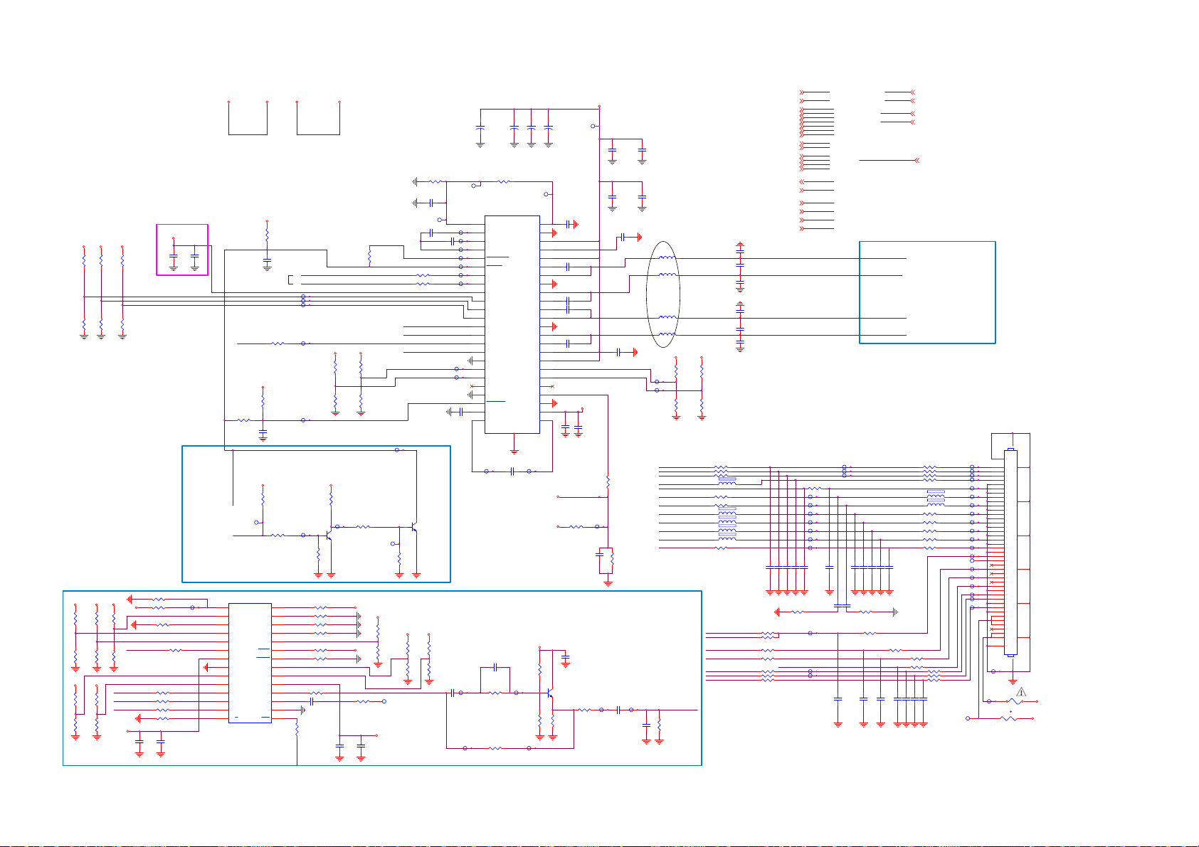
8-5-17 AUDIO-2nd-CLASS-D-AMP
+3V3-AUDIO2
+3V3
+3V3 +3V3
R5212
NC/10K+-5%1/16W
R5217
NC/10K+-5%1/16W
R5213
NC/10K+-5%1/16W
R5218
NC/10K+-5%1/16W
+3V3-AUDIO2
C5215
R5214
NC/10K+-5%1/16W
R5219
NC/10K+-5%1/16W
C5216
NC/1UF 16V
NC/100N16V
SOC-I2S-SD1
R5234
NC/0R05 OH M
AUDIO-PD2n
TP5279
AMP-PD2n
MUTE CIRCUIT
+3V3
R5296
R5306
NC/2.2K 1/ 16W
R5295
R5307
NC/2.2K 1/ 16W
+3V3
+3V3
R5316
R5317
NC/2.2K 1/ 16W
R5315
R5318
NC/2.2K 1/ 16W
NC/2.2K 1/ 16W
NC/2.2K 1/ 16W
NC/2.2K 1/ 16W
R5320
R5300
NC/2.2K 1/ 16W
SOC-I2S-BCLK
SOC-I2S-LRCK
SOC-I2S-SD1
+3V3
NC/2.2K 1/ 16W
SOC-I2S-MCLK
NC/2.2K 1/ 16W
+3V3
C5275
R5302 NC/2.2K 1/16W
R5301 NC/2.2K 1/16W
R5290 NC/47 OHM 1/16W
R5303 NC/47 OHM 1/16W
R5304 NC/47 OHM 1/16W
R5291 NC/47 OHM 1/16W
R5299 NC/2.2K 1/16W
C5274
NC/100N16V
NC/2.2U F 16V
R5319 NC/2.2K 1/16W
+3V3
+3V3
TP5295
U5201
1
CSS
2
COPY/C
3
L
4
CLK1
5
CLK0
6
MCLK
7
Vio
8
DGND
9
FMT0
10
FMT1
11
SCLK
12
SYNC
13
SDATA
14
M/S
NC/DI T4096IPWR
+3V3
+3V3
R5211
NC/10K+-5%1/16W
Use I2C net type
R5220
NC/0R05 OH M
+3V3
R5227
NC/10K+-5%1/16W
C5238
NC/1uF 10V
+3V3
R5243
NC/100K 1/16W
R5251
NC/10K+-5%1/16W
MODE
U
V
BLS
BLSM
EMPH
AUDIO
MONO
MDAT
VDD
TX+
TX-
DGND
RST
+12V-AUDIO2
C5218
NC/100N16V
R5254
NC/10K+-5%1/16W
28
27
26
25
24
23
22
21
20
19
18
R5321 NC/47 OHM 1/16W
17
16
15
AUDIO-RESET n
+12V-AUDIO
SDA-SSB
SCL-SSB
TP5286
TP5287
TP5288
TP5284
+3V3
TP5283
+3V3
R5244
NC/100K 1/16W
TP5278
TP5282
Q5201
NC/LBC847BW T1G
R5292 NC/2.2K 1/16W
R5293 NC/2.2K 1/16W
R5294 NC/2.2K 1/16W
R5314 NC/2.2K 1/16W
R5297 NC/2.2K 1/16W
R5298 NC/2.2K 1/16W
C5276
NC/100N16V
R5305
NC/47 OHM 1/16W
+3V3
R5221
NC/10K+-5%1/16W
R5228
NC/10K+-5%1/16W
R5247
NC/10K+-5%1/16W
+3V3
+3V3
R5288
NC/100OHM1/16W
C5272
NC/100N16V
R5210
NC/1K 1/16W
R5222
NC/10K+-5%1/16W
R5229
NC/10K+-5%1/16W
TP5281
R5255
NC/10K+-5%1/16W
+3V3
R5308
R5309
+5V-SW
C5273
NC/2.2U F 16V
R5215 NC/47 OHM 1/16W
R5216 NC/47 OHM 1/16W
SOC-I2S-MCLK
SOC-I2S-BCLK
SOC-I2S-LRCK
TP5280
+3V3
NC/2.2K 1/ 16W
NC/2.2K 1/ 16W
R5310
NC/2.2K 1/ 16W
R5311
NC/2.2K 1/ 16W
TP5317
R5206
NC/47K 1/16W
C5258
NC/1UF16V
TP5264
C5212
NC/1UF16V
NC/1UF 16V
Q5200
NC/LBC847BW T1G
+3V3
R5312
NC/2.2K 1/ 16W
R5313
NC/2.2K 1/ 16W
+
+
+
NC/220UF 16V
GVDD_REG
BSTRPBA+
SPK_OUTA+
SPK_OUTA-
SPK_OUTB+
E-PAD
49
C5243
NC/1uF 10V
C5203
GGND
PGND
BSTRPABSTRPB-
PGND
BSTRPB+
DR_INB-
DR_INB+
DR_OUTB
DR_UVP
DRGND
DRVDD
DR_CP
NC/220UF 16V
TP5227
AVDD
PVDD
PVDD
PVDD
PVDD
TP5277
+12V-AUDIO2
+
C5204
NC/220UF 16V
48
47
46
45
44
43
42
41
40
39
38
37
36
35
34
33
32
31
30
29
28
27
26
25
+3V3
C5213
TP5228
TP5265
TP5266
TP5267
TP5268
TP5269
TP5270
TP5271
TP5272
TP5273
C5236
NC/1UF 16V
C5201
NC/220UF 16V
R5207
NC/47K 1/16W
U5200
1
SFT_CLIP
2
AVDD_REG
3
VCOM
4
AVSS
5
SPK_FAULT
6
SPK_SD
7
SDA/FREQ
8
SCL/PBTL
9
DVDD
10
SPK_GAIN0
11
SPK_GAIN1
SPK_MUTE12SPK_OUTB-
13
MCLK
14
SCLK
15
SDIN
16
LRCLK
17
DGND
18
DR_INA-
19
DR_INA+
20
DR_OUTA
21
DRGND
22
DR_MUTE
23
DRVSS
24
DR_CN
NC/TAS5760LD
TP5276
AUDIO MODULE S PDIF OUTPUT
+3V3
C5267
NC/100N16V
TP5294
TP5291
C5269
NC/10PF 50V
R5282
NC/2K7
R5237
NC/0R05 OH M
TP5293
NC/4.7K 1/ 16W
R5284
TP5292
R5283
NC/4.7K 1/ 16W
C5205
C5257
NC/1UF 16V
C5220
NC/220NF 25V
C5225
NC/220NF 25V
C5226
NC/220NF 25V
C5231
NC/220NF 25V
C5239N C/100N16V
R5248
NC/150K 1/16W 5%
NC/470PF 50V
C5268
NC/100N16V
Q5202
NC/LBC847BW T1G
NC/47 OHM 1/16W
R5285
NC/180R 1/ 16W 5%
TP5226
+3V3-AUDIO2
C5240NC/1UF16V
NC/22K 1/16W
C5247
R5286
+12V-AUDIO2
R5239
TP5275
TP5290
C5214
C5234
NC/100N16V
R5256
NC/3.9K 1/ 16W
C5270
NC/100N16V
C5206
NC/10UF 16V
C5208
NC/1UF 16V
NC/100N16V
TP5289
C5271
NC/22pF 50V
C5207
NC/10UF 16V
C5210
NC/1UF 16V
9/3
L5200
NC/10UH 20%
L5201
NC/10UH 20%
L5202
NC/10UH 20%
L5203
NC/10UH 20%
+3V3
TP5251
TP5252
RC-IR
POWER-ON
NT-LCD-PWR-ON
SOC-TX-BO
SOC-RX-BO
SOC-I2S-LRCK
SOC-I2S-BCLK
SOC-I2S-SD0
SOC-I2S-SD1
SOC-I2S-SD2
SOC-I2S-SD3
SOC-I2S-MCLK
AUDIO-MODULE-SPDIF
R5287
NC/120 OHM 1/16W
+3V3
R5224
R5223
NC/10K+-5%1/16W
NC/10K+-5%1/16W
R5230
R5231
NC/10K+-5%1/16W
NC/10K+-5%1/16W
R5235 NC/100OHM1/16W
1 2
FB5200 NC/ 220R
R5241 NC/100OHM1/16W
R5249 NC/100OHM1/16W
1 2
FB5202 NC/ 220R
1 2
FB5203 NC/ 220R
1 2
FB5204 NC/ 220R
1 2
FB5205 NC/ 220R
SOC-3D-IR
NT-3D-IR
NT-CTRL-DISP6
NT-CTRL-DISP1
SDA-SSB
SCL-SSB
AUDIO-RESETn
NT-LCD-PWR-ON8,9,15
AUDIO-RESETn17,19,25
SOC-I2S-MCLK17, 22
SOC-I2S-BCLK17,22
SOC-I2S-LRCK17,22
SOC-I2S-SD017,22
SOC-I2S-SD122
SOC-I2S-SD222
SOC-I2S-SD322
SDA-SSB2,17
SCL-SSB2,17
LSPK2p17
LSPK2n17
RSPK2p17
RSPK2n17
AMP-PD2n17
AUDIO-PD2n17
RC-IR2, 23,25
POWER-ON15
SOC-3D-IR19,23
NT-3D-IR8,23
NC/1UF 16V
C5217
C5221
NC/1UF 16V
C5223
NC/1UF 16V
NC/1UF 16V
C5227
C5230
NC/1UF16V
C5232
NC/1UF 16V
C5237NC/1nF 50V
C5241NC/1nF 50V
C5235NC/1nF 50V
NC/22 OHM 1/16W
R5265 NC/0R05 OHM
R5266 NC/100OHM1/16W
R5278 NC/47 OHM 1/16W
R5276 NC/47 OHM 1/16W
R5270 NC/47 OHM 1/16W
NT-LCD-PWR-ON
AUDIO-RESETn
SOC-I2S-MCLK
SOC-I2S-BCLK
SOC-I2S-LRCK
SOC-I2S-SD0
SOC-I2S-SD1
SOC-I2S-SD2
SOC-I2S-SD3
SDA-SSB
SCL-SSB
LSPK2p
LSPK2n
RSPK2p
RSPK2n
AMP-PD2n
AUDIO-PD2n
RC-IR
POWER-ON
SOC-3D-IR
NT-3D-IR
R5242 NC/47 OHM 1/16W
TP5233
TP5234
TP5235
TP5236
TP5237
TP5238
TP5239
C5242NC/1nF 50V
C5244NC/10PF 50V
C5259NC/10PF 50V
C5245
NC/47pF 50V
R9517
TP5240
TP5248
TP5249
AUDIO-MODULE-SPDIF
TP5229
TP5230
TP5231
C5248NC/330pF 50V
C5249NC/330pF 50V
C5246
NC/47pF 50V
R9516
NC/22 OHM 1/16W
R5267 NC/0R05 OHM
C5253N C / 100pF 50V
C5262NC/100N16V
SOC-TX-BO
SOC-TX-BO 2
SOC-RX-BO
SOC-RX-BO 2
NT-CTRL-DISP1
NT-CTRL-DISP1 8,9
NT-CTRL-DISP6
NT-CTRL-DISP6 8,9
AUDIO-MODULE-SPD IF 22
SPEAKER connection
LSPK2p
LSPK2n
connector on 1st
CLASS-D schematic
RSPK2n
RSPK2p
BO AUDIO connector
R5226 NC/100OHM1/16WR5225 NC/100OHM1/16W
R5233 NC/100OHM1/16WR5232 NC/100OHM1/16W
R5236 NC/100OHM1/16W
R5238 NC/100OHM1/16W
FB5206 NC/ 220R
FB5207 NC/ 220R
R5253 NC/100OHM1/16W
R5258 NC/100OHM1/16W
R5260 NC/100OHM1/16W
R5262 NC/100OHM1/16W
R5264 NC/0R05 OHMR5263 NC/100OHM1/16W
C5250NC/330pF 50V
C5251NC/330pF 50V
C5252NC/1nF 50V
R5259 NC/0R05 OHM
R5252 NC/0R05 OHM
R5246 NC/0R05 OHM
R5269 NC/0R05 OHMR5268 NC/47 OHM 1/16W
R5271 NC/0R05 OHM
R5273 NC/100OHM1/16WR5272 NC/100OHM1/16W
C5254NC / 10PF 50V
C5255NC / 10PF 50V
C5264NC/100N16V
C5266NC/1nF 50V
1 2
1 2
C5256N C / 10PF 50V
TP5217
TP5200
TP5201
TP5202
TP5203
TP5204
TP5205
TP5206
TP5207
TP5208
TP5209
TP5210
TP5211
TP5212
TP5218
TP5220
TP5222
TP5224
TP5213
TP5214
TP5215
CN1103
51
1
2
3
4
5
6
7
8
9
10
11
12
13
14
15
16
17
18
19
20
21
22
23
24
25
26
27
28
29
30
31
32
33
34
35
36
37
38
39
40
41
50
TP5225
F5200
1 2
TP5216
NC/T 2A 63V
1 2
TH5200 NC/PTCR
4849
42
43
44
45
46
47
+12V
t
+3V3
Page 71

8-5-18 SOC-GPIO & PCMCIA
I
CI_A0
CI_A1
CI_A2
CI_A3
CI_A4
CI_A5
CI_A6
CI_A7
CI_A8
CI_A9
CI_A10
CI_A11
CI_A12
CI_A13
CI_A14
CI_MCLKI
CI_MIVAL
CI_MISTRT
CI_MDI0
CI_MDI1
CI_MDI2
CI_MDI3
CI_MDI4
CI_MDI5
CI_MDI6
CI_MDI7
CI_D0
CI_D1
CI_D2
CI_D3
CI_D4
CI_D5
CI_D6
CI_D7
CI_MDO0
CI_MDO1
CI_MDO2
CI_MDO3
CI_MDO4
CI_MDO5
CI_MDO6
CI_MDO7
SOC-LOCKn
TP6106
SOC-HTPDn
TP6107
TCON-L R
R6160 NC/100OH M1/16W
12V-DETECT
CI-OCP
TP6108
CI-RESET
TP6109
CI-PWR-EN
TP6110
GFX-HTPDn
TP6111
SOC-3D-LR
R6153 NC/100OHM1/16W
SOC-3D-IR
R6154 NC/100OHM1/16W
EEPROM-WP
R6155 10OHM1/16W R6156 10OHM1/16W
AUDIO-RESETn
R6157 10OHM1/16W
HP-DETECTn
TP6112
LNB_LINEDROP
TP6115
KEYBOARD
AMBI-TEMP
TUN_LNB
R6163 10OHM1/16W
R6164 10OHM1/16W
R6165 10OHM1/16W
+3V3
+3V3
+3V3
+3V3
YPBPR-DETECT
USB-RESETn
TP6114 R6173 10OHM1/16W
CAMERA-PWR-EN
TP6116
SCART-STATUS
POWER-OK
R6167 6.8K 1/16W
R6174 6.8K 1/16W
R6176 6.8K 1/16W
R6179 6.8K 1/16W
Place resistors
close to SOC
AK25
AL27
AM27
AN27
AN28
AM28
AL28
AR37
AU38
AN36
AM36
AK37
C1
C2
B1
C3
B2
A2
A3
A4
E11
E12
D13
D12
A5
C9
C8
D11
B6
B8
A8
A7
B7
C7
B5
D10
C5
B4
F8
E5
D4
F16
E15
E13
C10
E14
E6
D5
C4
D15
F14
B10
B9
D14
D3
G16
D17
F5
E4
B3
F4
E10
E9
D6
C6
E8
D8
L34
P35
L35
E33
L33
M33
J35
U37
N35
N34
U9400-8
CI_A0
CI_A1
CI_A2
CI_A3
CI_A4
CI_A5
CI_A6
CI_A7
CI_A8
CI_A9
CI_A10
CI_A11
CI_A12
CI_A13
CI_A14
CI_MCLKI
CI_MIVAL
CI_MISTRT
CI_MDI0
CI_MDI1
CI_MDI2
CI_MDI3
CI_MDI4
CI_MDI5
CI_MDI6
CI_MDI7
CI_D0
CI_D1
CI_D2
CI_D3
CI_D4
CI_D5
CI_D6
CI_D7
CI_MDO0
CI_MDO1
CI_MDO2
CI_MDO3
CI_MDO4
CI_MDO5
CI_MDO6
CI_MDO7
GPIO42
GPIO43
GPIO44
GPIO45
GPIO46
GPIO47
GPIO48
GPIO49
GPIO50
GPIO51
GPIO52
GPIO53
GPIO54
GPIO55
GPIO56
GPIO57
GPIO58
GPIO59
GPIO60
GPIO61
GPIO62
GPIO63
GPIO64
GPIO65
GPIO66
ADIN0_SRV
ADIN1_SRV
ADIN2_SRV
ADIN3_SRV
ADIN4_SRV
ADIN5_SRV
ADIN6_SRV
ADIN7_SRV
ADIN8_SRV
ADIN9_SRV
MT5593UGIJ
DIVERSITY-1
DIVERSITY-2
DIVERSITY-3
DIVERSITY-4
GPIO0
DEMOD_RST
GPIO1
DEMOD_TSCLK
GPIO2
DEMOD_TSDATA0
GPIO3
DEMOD_TSDATA1
GPIO4
DEMOD_TSDATA2
GPIO5
DEMOD_TSDATA3
GPIO6
DEMOD_TSDATA4
GPIO7
DEMOD_TSDATA5
GPIO8
DEMOD_TSDATA6
GPIO9
DEMOD_TSDATA7
GPIO10
DEMOD_TSSYNC
GPIO11
DEMOD_TSVAL
GPIO12
GPIO13
GPIO14
GPIO15
CI_TSDATA0
GPIO16
CI_TSSYNC
GPIO17
GPIO18
GPIO19
PVR_TSCLK
GPIO20
PVR_TSVAL
GPIO21
PVR_TSSYNC
GPIO22
PVR_TSDATA0
PVR_TSDATA1
GPIO23
GPIO24
GPIO25
GPIO26
GPIO27
GPIO28
GPIO29
GPIO30
GPIO31
GPIO32
GPIO33
GPIO34
GPIO35
GPIO36
GPIO37
GPIO38
GPIO39
GPIO40
GPIO41
VCC3IO_SD
R6168 6.8K 1/16W
R6175 NC/10K+-5%1/ 16W
R6177 NC/10K+-5%1/ 16W
R6178 NC/10K+-5%1/ 16W
CI_INT
CI_TSCLK
CI_TSVAL
SPI_CLK1
SPI_CLK
SPI_DATA
SPI_CLE
OPWM0
OPWM1
OPWM2
OPWM3
OPWM4
OPWM5
OPWM6
OPWM7
OPWM8
SD_D0
SD_D1
SD_D2
SD_D3
SD_CMD
SD_CLK
LED_PWM0
LED_PWM1
LED_PWM2
LED_PWM3
OPCTRL0
OPCTRL1
OPCTRL2
OPCTRL3
OPCTRL4
OPCTRL5
OPCTRL6
OPCTRL7
OPCTRL8
OPCTRL9
OPCTRL10
OPCTRL11
OPCTRL12
OPCTRL13
OPCTRL14
OPCTRL15
OPCTRL16
OPCTRL17
OPCTRL18
OPCTRL19
OPCTRL20
E20
A14
D19
F22
G22
H22
H23
G23
F25
F23
D20
F20
A10
C14
C13
B13
A13
B12
D18
E17
F17
G17
C12
B11
A11
C11
AP38
AL30
AP37
AN35
AL36
AM35
AL34
AK35
AK34
D1
E2
E1
F2
D2
F3
D9
AA33
AA32
AF37
AG36
R34
R36
R33
W35
Y34
T35
N33
U35
R35
Y33
AC35
AB37
AC32
AG33
AE33
AD33
AD32
AC33
AD37
AD38
AD36
DEMOD_RST
DEMOD_TSCLK
DEMOD_TSDATA0
DEMOD_TSDATA1
DEMOD_TSDATA2
DEMOD_TSDATA3
DEMOD_TSDATA4
DEMOD_TSDATA5
DEMOD_TSDATA6
DEMOD_TSDATA7
DEMOD_TSSYNC
DEMOD_TSVAL
CI_INT
CI_TSCLK
CI_TSDATA0
CI_TSSYNC
CI_TSVAL
PVR_TSCLK
PVR_TSVAL
PVR_TSSYNC
PVR_TSDATA0
PVR_TSDATA1
SPI_CLK1
SPI_CLK
SPI_DATA
SPI_CLE
TP6148
TP6149
LED-PWM0
LED-PWM1
LED-PWM2
TP6143
R6146 NC/ 10OHM
TP6144
R6147 10OHM
R6152 10OHM1/16W
R6182 10OHM1/16W
R6181 10OHM1/16W
Place close
to SOC
R6148 10OHM1/16W
R6149 10OHM1/16W
TP6141
TP6142
TP6132
R6169 10OHM1/16W
R6170 10OHM1/16W
R6171 10OHM1/16W
TP6136
R6172 10OHM1/16W
TP6137
R6159 10OHM1/16W
SOC-AMBI-SPI-MOSI
SOC-AMBI-SPI-CLK
R6150 10OHM1/16W
R6151 10OHM1/16W
Place close
to SOC
BL-I-CTRLn
BL-DIM1n
TP6105
R6180
C6131
100N16V
WIFI-IRQn
WIFI -PWR-EN
LAN-PWR-EN
DDR-PWR-EN
MHL-PWR-EN
HDMI-ARC-SEL0
HDMI-ARC-SEL1
BT-IRQn
+3V3
R6183
100K 1/16W
NC/100N 16V
LED1
LED2
SPI_CLK1 CI_CD2#
SPI_CLE CI_IOWR#
CI_TSCLK CI_CE1#
CI_TSVAL CI_OE#
CI_TSSYNC CI_WE#
PVR_TSDATA0 CI_IREQ#
PVR_TSVAL CI_VS1#
R6184
100K 1/16W
AUDIO-MODULE-DETECT
AUDIO-MODULE-PAIRED
SPEAKER-DETECTn
100K 1/16W
+3V3
C6132
Place close
to SOC
TP6113R6158 10OHM1/16W
CI_CD1#SPI_CLK
CI_IORD#SPI_DATA
CI_REG#CI_INT
CI_WAIT#PVR_TSDATA1
PCMCIA Slot
CI_VCC
CI_D3
CI_D4
CI_D5
CI_D6
CI_D7
CI_CE1#
CI_A10
CI_OE#
CI_A11
CI_A9
CI_A8
CI_A13
CI_A14
CI_WE#
CI_IREQ#
CI_MIVAL_R
CI_MCLKI_R
CI_A12
CI_A7
CI_A6
CI_A5
CI_A4
CI_A3
CI_A2
CI_A1
CI_A0
CI_D0
CI_D1
CI_D2
CN1303
1
2
3
4
5
6
7
8
9
10
11
12
13
14
15
16
17
18
19
20
21
22
23
24
25
26
27
28
29
30
31
32
33
34
PCMCIA CAR
CI_MDI5
CI_MDI4
CI_MIVAL
CI_MDI3
CI_MISTRT
CI_MDI0
CI_MDI1
CI_MDI2
CI_MDI6
CI_MDI7
CI_MCLKI
GND
D3
D4
D5
D6
D7
CE1#
A10
OE#
A11
A9
A8
A13
A14
WE#
READY#:I REQ#
VCC
VPP1
A16
A15
A12
A7
A6
A5
A4
A3
A2
A1
A0
D0
D1
D2
WP#
GND
GND
CD1#
D11
D12
D13
D14
D15
CE2#
VS1#
IORD#
IOWR#
A17
A18
A19
A20
A21
VCC
PCMCIA
VPP2
A22
A23
A24
A25
VS2#
RESET
WAIT#
INPACK
REG#
BVD2#:SPKR
BVD1#:STSCHG
D8
D9
D10
CD2#
GND
69697070717172
72
R6101 47R 1/16W 5%
R6102 47R 1/16W 5%
R6103 47R 1/16W 5%
R6104 47R 1/16W 5%
R6105 47R 1/16W 5%
R6106 47R 1/16W 5%
R6107 47R 1/16W 5%
R6108 47R 1/16W 5%
R6109 47R 1/16W 5%
R6110 47R 1/16W 5%
R6111 47R 1/16W 5%
Closed to Main Chip
35
36
CI_CD1#
37
CI_MDO3_R
38
CI_MDO4_R
39
CI_MDO5_R
40
CI_MDO6_R
41
CI_MDO7_R
42
CI_CE2#
43
CI_VS1#
44
CI_IORD#
45
CI_IOWR#
46
CI_MISTRT_R
47
CI_MDI0_R
48
CI_MDI1_R
49
CI_MDI2_R
50
CI_MDI3_R
51
52
53
54
55
56
57
58
59
60
61
62
63
64
65
66
67
68
CI_MDI4_R
CI_MDI5_R
CI_MDI6_R
CI_MDI7_R
CI_MCLKO_R
CI-RESET
CI_WAIT#
CI_REG#
CI_MOVAL_R
CI_MOSTRT_R
CI_MDO0_R
CI_MDO1_R
CI_MDO2_R
CI_CD2#
CI_MDI5_R
CI_MDI4_R
CI_MIVAL_R
CI_MDI3_R
CI_MISTRT_R
CI_MDI0_R
CI_MDI1_R
CI_MDI2_R
CI_MDI6_R
CI_MDI7_R
CI_MCLKI_R
CI_VCC
CI_VCCCI_VCC
CI 3V3 PWR Cap.
C6101
NC/10PF 50V
CI_DVDD3V3
R6124
10K 1/16W 5%
C6104
100NF 16V
Closed to CI Conne ctor
+3V3
R6126
R6125
10K 1/16W 5%
10K 1/16W 5%
CI_CD2# CI_VS1#
C6105
100NF 16V
C6103
100NF 16V
CI_DVDD3V3
CI_VCCCI_DVDD3V3CI_DVDD3V3
R6127
10K 1/16W 5%
CI_WAIT#CI_CD1#
CI_VCC
R6129
10K 1/16W 5%
CI_IREQ#
CI_VCC
10K 1/16W 5%
R6128
CI_CE2#
Closed to CI SLOT
PVR_TSCLK
CI_TSDATA0
CI_MDO0
CI_MDO1
CI_MDO2
CI_MDO3
CI_MDO4
CI_MDO5
CI_MDO6
CI_MDO7
PVR_TSSY NC
C6102
NC/10PF 50V
R6112 47R 1/ 16W 5%
R6113 47R 1/ 16W 5%
R6114 47R 1/ 16W 5%
R6115 47R 1/ 16W 5%
R6116 47R 1/ 16W 5%
R6117 47R 1/ 16W 5%
R6118 47R 1/ 16W 5%
R6119 47R 1/ 16W 5%
R6120 47R 1/ 16W 5%
R6121 47R 1/ 16W 5%
R6122 47R 1/ 16W 5%
Closed to CI SLOT
CI_MOVAL_R
CI_MOSTRT_R
CI_MDO0_R
CI_MDO1_R
CI_MDO2_R
CI_MDO3_R
CI_MDO4_R
CI_MDO5_R
CI_MDO6_R
CI_MDO7_R
CI_MCLKO_R
Parallel TS from DEMOD
DEMOD_RST6
DEMOD_TSCLK6
DEMOD_TSSYNC6
DEMOD_TSVAL6
DEMOD_TSDATA06
DEMOD_TSDATA16
DEMOD_TSDATA26
DEMOD_TSDATA36
DEMOD_TSDATA46
DEMOD_TSDATA56
DEMOD_TSDATA66
DEMOD_TSDATA76
LNB_LINED ROP16
12V-DETECT15,17
AUDIO-RESETn17,18,25
YPBPR-DETECT22
SCART-STATUS22
KEYBOARD23
POWER-OK15
WIFI-PWR-EN16
LAN-PWR-EN24
DDR-PWR-EN15
HDMI-ARC-SEL021
HDMI-ARC-SEL121
MHL-PW R-EN20
AMBI-TEMP23
SOC-AMBI-SPI-MOSI8
SOC-AMBI-SPI-CLK8
AUDIO-MODULE-DETECT22
AUDIO-MODULE-PAIR ED22
SPEAKER-DETECTn17
HP-DETECTn17
Closed to Main Chip
Place close
to SOC
CI Bus Power Control
+5V-SW: Trace width > 60 mil
+5V-SW
C6206
1UF 10% 16V
CI-PWR-EN CI-OCP
R6215
4.7K 1/16W
CI_PWR_EN :
Enable : High
Disable : Low
CLOSE TO CI CONN E CTOR
U6201
1
5
VOUT
VIN
2
GND
4
OCB3EN
APL3511CBI-TRG
+3V3
CI_OCP :
Disable : Low
R6220
4.7K 1/16W
FB6209
120R 3A
TP6200
1 2
R6216
10K+-5%1/16W
TP6202
Regulator for 300mA output Current
C6207
100N16V
C6209
10UF 10V
CI_VCC
LED-PWM02
LED-PWM12
LED-PWM22
TUN_ LNB16
EEPROM-WP2
BT-IRQn24
LED123
LED223
SOC-LOCKn7
SOC-HTPDn7
SOC-3D-LR8
SOC-3D-IR18, 23
BL-I-CTRLn8, 15
BL-DIM1n8
WIFI-IRQn24
TCON-L R
DEMOD_RST
DEMOD_TSCLK
DEMOD_TSSYNC
DEMOD_TSVAL
DEMOD_TSDATA0
DEMOD_TSDATA1
DEMOD_TSDATA2
DEMOD_TSDATA3
DEMOD_TSDATA4
DEMOD_TSDATA5
DEMOD_TSDATA6
DEMOD_TSDATA7
LED-PWM0
LED-PWM1
LED-PWM2
LED1
LED2
LNB_LINED ROP
TUN_ LNB
EEPROM-WP
SOC-LOCKn
SOC-HTPDn
SOC-3D-LR
SOC-3D-IR
BL-I-CTRLn
BL-DIM1n
WIFI-IRQn
12V-DETECT
AUDIO-RESETn
YPBPR-DETECT
SCART-STATUS
KEYBOARD
POWER-OK
WIFI-PWR-EN
LAN-PWR-EN
DDR-PWR-EN
HDMI-ARC-SEL0
HDMI-ARC-SEL1
MHL-PW R-EN
BT-IRQn
AMBI-TEMP
SOC-AMBI-SPI-MOSI
SOC-AMBI-SPI-CLK
AUDIO-MODULE-DETECT
AUDIO-MODULE-PAIRED
SPEAKER-DETECTn
HP-DETECTn
TCON- LR 9
tem number in function group 6 sub-group1
Page 72

8-5-19 HDMI-INPUTS
HDMI4 Connected to RX port 0
CN1308
20
SHLD0
1
TMDSD2+
SHLD2
SHLD3
SHLD1
HDMI 19P
DSHLD0
TMDSD 2TMDSD1+
DSHLD1
TMDSD 1TMDSD0+
DSHLD2
TMDSD 0-
TMDSC+
CSHLD0
TMDSC-
DDC_GND
2
3
4
5
6
7
8
9
10
11
12
13
CEC
14
NC
15
SCL
16
SDA
17
18
VCC5
19
HPD
22
23
21
7/22
0R05 OHM
0R05 OHM
OPWR0_5V
HPD0
R7144
0R05 OHM
R7161
R7162
R7157
1K 1/16W
TP7326
R7154
33R 1/16W 5%
HDMI0-HPD-CBU S
HDMI0-RX2P
HDMI0-RX2N
HDMI0-RX1P
HDMI0-RX1N
HDMI0-RX0P
HDMI0-RX0N
HDMI0-RXCP
HDMI0-RXCN
HDMI-CEC-IN
HDMI0-ARC
SCL0
SDA0
MHL-P WR -EN
CD-SENSE
OPWR0_5V
MHL-S ENSE
CD-SENSE
R7168
100K 1/16W
TP7315
HDMI0-RX2P 21
HDMI0-RX2N 21
HDMI0-RX1P 21
HDMI0-RX1N 21
HDMI0-RX0P 21
HDMI0-RX0N 21
HDMI0-RXCP 21
HDMI0-RXCN 21
HDMI0-ARC 21
HDMI0-5V
0R05 OHM
NC/0R 05 OH M
R7155
330K +-5% 1/16W
EC SMD 220UF 20% 16V 6.3 * 7. 7
Q7101
AO3401A
13
ZD7100
BAT54
MMBT3904
R7105
820R
R7166
R7167
Q7100
+5V-SW
TP7314
MMBT3904
R7141
47K 1/16W
TP7312
220uF 16V
R7100
10K 1/16W 5%
R7101
100R 1/16W 5%
Q7105
D7105
LBAT54CWT1G
132
+5V-SW
+
C7109
R7150
47K 1/16W
HDMI0-SCL
HDMI0-SDA
OPWR0_5V
TP7313
R7102
20K 1/16W 5%
R7103
47K 1/16W 5%
CD-SENSE
HDMI0-5V track minimum 0.5mm
U7122
1
EN
OC
2
GND
OUT
IN3OUT
G529A1TB1U
C7112
1uF 10V
+3V3-STANDBY
MHL-S ENSE
R7104
300K
CD-SENSE
C7111
100N16V
+3V3-STAN DBY
6
5
4
TP7325
R7151
10K+-5%1/16W
OPWR0_5V
C7105
10UF 16V
TP7311
R7156
10K+-5%1/16W
HDMI3 Connected to RX port 1
Located at right side IO (looking from backside TV)
CN1307
21
SHLD1
19
HPD1
HPD
SHLD3
SHLD2
SHLD0
HDMI 19P
DDC_GND
TMDSCCSHLD0
TMDSC+
TMDSD0-
DSHLD2
TMDSD 0+
TMDSD1-
DSHLD1
TMDSD 1+
TMDSD2-
DSHLD0
TMDSD 2+
VCC5
18
17
16
SDA
15
SCL
14
NC
13
CEC
12
11
10
9
8
7
6
5
4
3
2
1
23
22
20
TP7324
OPWR1_5V
SDA1
SCL1
HDMI1-ARC
HDMI1-ARC 21
HDMI-CEC-IN
HDMI1-RXCN
HDMI1-RXCN 21
HDMI1-RXCP
HDMI1-RXCP 21
HDMI1-RX0N
HDMI1-RX0N 21
HDMI1-RX0P
HDMI1-RX0P 21
HDMI1-RX1N
HDMI1-RX1N 21
HDMI1-RX1P
HDMI1-RX1P 21
HDMI1-RX2N
HDMI1-RX2N 21
HDMI1-RX2P
HDMI1-RX2P 21
PCB Layout for TMDS RX signals:
Differential impedance 100 Ohm
OPWR1_5V
HPD1
R7106
100K 1/16W
C7107
100N16V
1K 1/16W
MMBT3904
HDMI2 Connected to RX port 2
CN1306
20
SHELL1
1
D2+
2
D2 Shield
SHELL3
SHELL4
SHELL2
HDMI 19P
D1 Shield
D0 Shield
CK Shield
CE Remote
DDC CLK
DDC DATA
HP DET
3
D2-
4
D1+
5
6
D1-
7
D0+
8
9
D0-
10
CK+
11
12
CK-
13
14
NC
15
16
17
GND
18
+5V
19
22
23
21
OPWR2_5V
HPD2
HPD2
OPWR2_5V
100K 1/16W
TP7318
R7112
HDMI2-RX2P
HDMI2-RX2N
HDMI2-RX1P
HDMI2-RX1N
HDMI2-RX0P
HDMI2-RX0N
HDMI2-RXCP
HDMI2-RXCN
HDMI-CEC-IN
HDMI2-ARC
SCL2
R7158
1K 1/16W
C7106
100N16V
HDMI2-RX2P 21
HDMI2-RX2N 21
HDMI2-RX1P 21
HDMI2-RX1N 21
HDMI2-RX0P 21
HDMI2-RX0N 21
HDMI2-RXCP 21
HDMI2-RXCN 21
HDMI2-ARC 21
Q7103
MMBT3904
R7160
Q7102
HDMI2-5V
R7110
1K 1/16W
R7109
1K 1/16W
TP7317
1K 1/16W
SCL1
SDA1
4K7 1/16W 5%
R7107
1K 1/16W
R7111
4K7 1/16W 5%
R7113
HDMI1-5V
R7146
47K 1/16W
R7108
TP7323TP
R7149
47K 1/16W
HDMI2-HPD
HDMI1-5V
HDMI1-HPD
R7148
47K 1/16W
HDMI2-5V
R7147
47K 1/16W
HDMI2-SCL
HDMI2-SDASDA2
TP7321
TP7322
TP7319
TP7320
HDMI1-SCL
HDMI1-SDA
TP7330
TP7331
HDMI1 Connected to RX port 3
Located at bottom side IO left (look ing from backside TV)
CN1305
20
SHELL1
1
D2+
2
D2 Shield
SHELL3
SHELL4
SHELL2
HDMI 19P
D1 Shield
D0 Shield
CK Shield
CE Remote
DDC CLK
DDC DATA
HP DET
3
D2-
4
D1+
5
6
D1-
7
D0+
8
9
D0-
10
CK+
11
12
CK-
13
14
NC
15
16
17
GND
18
+5V
19
22
23
21
HPD3
OPWR3_5V
HPD3
HDMI3-RX2P
HDMI3-RX2N
HDMI3-RX1P
HDMI3-RX1N
HDMI3-RX0P
HDMI3-RX0N
HDMI3-RXCP
HDMI3-RXCN
HDMI-CEC-IN
HDMI3-ARC
SCL3
SDA3
R7159
1K 1/16W
TP7310
OPWR3_5V
R7116
100K 1/16W
HDMI3-RX2P 21
HDMI3-RX2N 21
HDMI3-RX1P 21
HDMI3-RX1N 21
HDMI3-RX0P 21
HDMI3-RX0N 21
HDMI3-RXCP 21
HDMI3-RXCN 21
HDMI3-ARC 21
HDMI3-5V
TP7307
C7110
100N16V
MMBT3904
Q7104
HDMI0-SCL
HDMI1-SCL
HDMI2-SCL
HDMI3-SCL
HDMI0-SDA
HDMI1-SDA
HDMI2-SDA
HDMI3-SDA
HDMI0-HPD-CBU S
HDMI1-HPD
HDMI2-HPD
HDMI3-HPD
MHL- PW R-E N
HDMI-CEC-IN
MHL- SEN SE
HDMI0-5V
HDMI1-5V
HDMI2-5V
HDMI3-5V
HDMI3-5V
R7152
47K 1/16W
R7114
1K 1/16W
4K7 1/16W 5%
R7117
1K 1/16W
R7115
HDMI0-SCL 21
HDMI1-SCL 21
HDMI2-SCL 21
HDMI3-SCL 21
HDMI0-SDA 21
HDMI1-SDA 21
HDMI2-SDA 21
HDMI3-SDA 21
HDMI0-HPD-CBUS 21
HDMI1-HPD 21
HDMI2-HPD 21
HDMI3-HPD 21
MHL-PWR-EN 19
HDMI-CEC-IN 21
MHL-S ENSE 21
HDMI0-5V 21
HDMI1-5V 21
HDMI2-5V 21
HDMI3-5V 21
R7153
47K 1/16W
TP7308
TP7309
HDMI3-HPD
HDMI3-HPD
HDMI3-SCL
HDMI3-SDA
HDMI0 ESD
U7120
1
HDMI0-RX2P
CH1
NC
2
HDMI0-RX2N
CH2
NC
3
GND
VN
VN
4
HDMI0-RX1P
CH3
CH45NC
NC/AOZ8804DI
U7121
1
CH1
2
CH2
3
VN
4
CH3
CH45NC
NC/AOZ8804DI
U7119
1
CH1
2
CH2
3
VN
4
CH3
CH45NC
NC/AOZ8804DI
NC
NC
NC
VN
NC
NC
NC
VN
NC
HDMI0-RX1N
HDMI0-RX0P
HDMI0-RX0N
GND
HDMI0-RXCP
HDMI0-RXCN
SCL0
SDA0 SDA0
GND
OPWR0_5V
HPD0 HPD0
10
HDMI0-RX2P
9
HDMI0-RX2N
8
7
HDMI0-RX1P
6
HDMI0-RX1N
10
HDMI0-RX0P
9
HDMI0-RX0N
8
7
HDMI0-RXCP
6
HDMI0-RXCN
10
9
8
7
6
GND
GND
SCL0
GND
OPWR0_5V
HDMI1 ESD
HDMI1-RX2P
HDMI1-RX2N
GND
HDMI1-RX1P
HDMI1-RX1N
HDMI1-RX0P
HDMI1-RX0N
GND
HDMI1-RXCP
HDMI1-RXCN
SCL1
SDA1
GND
HPD1
U7124
1
CH1
2
CH2
3
VN
4
CH3
CH45NC
NC/AOZ 8804DI
U7125
1
CH1
2
CH2
3
VN
4
CH3
CH45NC
NC/AOZ 8804DI
U7123
1
CH1
2
CH2
3
VN
4
CH3
CH45NC
NC/AOZ 8804DI
HDMI2 ESD
10
HDMI1-RX2P
NC
9
HDMI1-RX2N
NC
8
GND
VN
7
HDMI1-RX1P
NC
6
HDMI1-RX1N
10
HDMI1-RX0P
NC
9
HDMI1-RX0N
NC
8
GND
VN
7
HDMI1-RXCP
NC
6
HDMI1-RXCN
10
SCL1
NC
9
SDA1
NC
8
GND
VN
7
OPWR1_5VOPWR1_5V
NC
6
HPD1
U7114
1
CH1
2
CH2
3
VN
4
CH3
CH45NC
NC/AOZ 8804DI
U7115
1
CH1
2
CH2
3
VN
4
CH3
CH45NC
NC/AOZ 8804DI
U7113
1
CH1
2
CH2
3
VN
4
CH3
CH45NC
NC/AOZ 8804DI
10
HDMI2-RX2P
NC
9
HDMI2-RX2N
NC
8
VN
7
HDMI2-RX1P
NC
6
HDMI2-RX1N
10
HDMI2-RX0P
NC
9
HDMI2-RX0N
NC
8
VN
7
HDMI2-RXCP
NC
6
HDMI2-RXCN
10
NC
9
NC
8
VN
7
OPWR2_5V
NC
6
HDMI2-RX2P
HDMI2-RX2N
GND
HDMI2-RX1P
HDMI2-RX1N
HDMI2-RX0P
HDMI2-RX0N
GND
HDMI2-RXCP
HDMI2-RXCN
SCL2
SDA2
GND
OPWR2_5V
HPD2 HPD2
GND
GND
SCL2
SDA2
HDMI3 ESD
GND
U7117
1
CH1
2
CH2
3
VN
4
CH3
CH45NC
NC/AOZ 8804DI
U7118
1
CH1
2
CH2
3
VN
4
CH3
CH45NC
NC/AOZ 8804DI
U7116
1
CH1
2
CH2
3
VN
4
CH3
CH45NC
NC/AOZ 8804DI
10
HDMI3-RX2P
NC
9
HDMI3-RX2N
NC
8
VN
7
HDMI3-RX1P
NC
6
HDMI3-RX1N
10
HDMI3-RX0P
NC
9
HDMI3-RX0N
NC
8
VN
7
HDMI3-RXCP
NC
6
HDMI3-RXCN
10
NC
9
NC
8
VN
7
NC
6
HDMI3-RX2P
HDMI3-RX2N
GND
HDMI3-RX1P
HDMI3-RX1N
HDMI3-RX0P
HDMI3-RX0N
GND
HDMI3-RXCP
HDMI3-RXCN
SCL3
SDA3
GND
OPWR3_5V O PWR3_5V
HPD3
GND
GND
SCL3
SDA3
HPD3
GND
Page 73

8-5-20 HDMI-SOC-ARC
HDMI-CEC-IN CEC
HDMI-C EC-IN20
HDMI0-SCL20
HDMI1-SCL20
HDMI2-SCL20
HDMI3-SCL20
HDMI0-SDA20
HDMI1-SDA20
HDMI2-SDA20
HDMI3-SDA20
HDMI0-5V20
HDMI1-5V20
HDMI2-5V20
HDMI3-5V20
HDMI0-HPD-CBUS20
HDMI1-HPD20
HDMI2-HPD20
HDMI3-HPD20
MHL-SENSE20
HDMI0-SCL
HDMI1-SCL
HDMI2-SCL
HDMI3-SCL
HDMI0-SDA
HDMI1-SDA
HDMI2-SDA
HDMI3-SDA
HDMI0-5V
HDMI1-5V
HDMI2-5V
HDMI3-5V
HDMI0-H PD-CBU S
HDMI1-HPD
HDMI2-HPD
HDMI3-HPD
MHL-SENSE
MHL-SENSE
R7214
NC/10K+-5 %1/16W
R7200
100OHM1/16W
+1V0-AVDD-HDMI
+1V0-AVDD-HDMI
+3V3-AVDD-HDMI
U9400-6
G24
HDMI_CEC
F26
HDMI_0_SCL
G30
HDMI_1_SCL
G31
HDMI_2_SCL
D34
HDMI_3_SCL
F27
HDMI_0_SDA
G28
HDMI_1_SDA
F33
HDMI_2_SDA
D33
HDMI_3_SDA
G26
HDMI_0_PWR5V
E30
HDMI_1_PWR5V
E31
HDMI_2_PWR5V
E34
HDMI_3_PWR5V
F28
HDMI_0_HPD_CBUS
F30
HDMI_1_HPD
F31
HDMI_2_HPD
F34
HDMI_3_HPD
F24
MHL_ SEN SE
B30
AVDD10_HDMI
A30
AVDD10_HDMI
P27
AVDD33_HDMI
P28
AVDD33_HDMI
MT5593UGIJ
HDMI_0_RX_0
HDMI_0_RX_0B
HDMI_0_RX_1
HDMI_0_RX_1B
HDMI_0_RX_2
HDMI_0_RX_2B
HDMI_0_RX_C
HDMI_0_RX_CB
HDMI_1_RX_0
HDMI_1_RX_0B
HDMI_1_RX_1
HDMI_1_RX_1B
HDMI_1_RX_2
HDMI_1_RX_2B
HDMI_1_RX_C
HDMI_1_RX_CB
HDMI_2_RX_0
HDMI_2_RX_0B
HDMI_2_RX_1
HDMI_2_RX_1B
HDMI_2_RX_2
HDMI_2_RX_2B
HDMI_2_RX_C
HDMI_2_RX_CB
HDMI_3_RX_0
HDMI_3_RX_0B
HDMI_3_RX_1
HDMI_3_RX_1B
HDMI_3_RX_2
HDMI_3_RX_2B
HDMI_3_RX_C
HDMI_3_RX_CB
A20
B20
A19
B19
A18
B18
A21
B21
C23
D23
C22
D22
A22
B22
A24
B24
A26
B26
C25
D25
C24
D24
C26
D26
C28
D28
A28
B28
C27
D27
C29
D29
HDMI0-RX0P 20
HDMI0-RX0N 20
HDMI0-RX1P 20
HDMI0-RX1N 20
HDMI0-RX2P 20
HDMI0-RX2N 20
HDMI0-RXCP 20
HDMI0-RXCN 20
HDMI1-RX0P 20
HDMI1-RX0N 20
HDMI1-RX1P 20
HDMI1-RX1N 20
HDMI1-RX2P 20
HDMI1-RX2N 20
HDMI1-RXCP 20
HDMI1-RXCN 20
HDMI2-RX0P 20
HDMI2-RX0N 20
HDMI2-RX1P 20
HDMI2-RX1N 20
HDMI2-RX2P 20
HDMI2-RX2N 20
HDMI2-RXCP 20
HDMI2-RXCN 20
HDMI3-RX0P 20
HDMI3-RX0N 20
HDMI3-RX1P 20
HDMI3-RX1N 20
HDMI3-RX2P 20
HDMI3-RX2N 20
HDMI3-RXCP 20
HDMI3-RXCN 20
Analog Power
+3V3-AVDD
+5V-SW
R7202
1K 1/16W 5%
C7211
NC/10NF 50V
+3V3-AVDD-HD MI
Q7106
AO3414
R7201
100K 1/16W 5%
TP7425
C7202
100N16V
+1V0-AVDD
+1V0-AVDD-HD MI
C7200
100N16V
C7201
NC/1uF 10 V
HDMI-ARC-SEL1
HDMI-ARC-SEL0
ARC
Schield ARC
HDMI-ARC-SEL1 19
HDMI-ARC-SEL0 19
ARC 22
Goes to Analog Video schema
Goes to PCMCIA schema
TP7428
TP7426
TP7429
HDMI1-ARC20
C7206
10PF 50V
TP7419
R7203
100R 1/16W 1%
ARC0
ARC3
R7212
100R 1/16W 1%
HDMI2-ARC20
C7207
10PF 50V
TP7420
TP7423
+3V3
ARC2
ARC1
HDMI-ARC-SEL0
HDMI-ARC-SEL1
TP7424
R7209
NC/10K+-5%1/ 16W
HDMI3-ARC20
C7208
10PF 50V
C7205
1uF 10V
TP7421
R7206
100R 1/16W 1%
TP7427
R7211
100R 1/16W 1%
HDMI0-ARC20
Each individual filter close to corresponding HDMI connector
HDMIx-ARC schield as much as possible with ground tracks
+5V-SW
16
15
14
13
12
11
10
9
74HC4051PW
U7201
VCC
Y2
Y1
Y0
Y3
S0
S1
S2
R7213
0R05 OHM
C7209
10PF 50V
1
Y4
2
Y6
3
Z
4
Y7
5
Y5
6
E
7
VEE
8
GND
Schield these nets in layout
ARC0
ARC1
ARC2
ARC3
TP7422
R7204
100R 1/16W 1%
1uF 10V
ARC-BUFF
TP7417
R7205
56R 1/16W 5%
HDMI-ARC-SEL0
HDMI-ARC-SEL1
TP7416
R7208
75 OHM +-1% 1/16W
R7215
NC/10K+-5%1/ 16W
Audi o Return Channel (ARC)
82R 1%
R7207
L
L
H
+3V3C7204
C7210
100N16V
U7202
5
VCC
4
SN74LVC1G125D CKR
R7210
NC/0R05 OHM
HDMI-ARC-SEL0HDMI-ARC-SEL1
R7216
NC/10K+-5%1/16W
pin1 Lo w = enab le
1
OE
2
A
GND3Y
L
H
L
HH
ARC
Schield ARC
Output
HDMI0
HDMI1
HDMI2
HDMI3
TP7418
Page 74

8-5-21 SCART-YPbPr-CVBS
CN1309
B
A
TP7506
ZD7500
3
NC/TVM1G5R5M100R
4
1 2
1
2
12
ZD7501
NC/TVM1G5R5M100R
CN1310
PHONE JACK 4P
DVI-AU DIO- IN (T O P )
CN1317
NC/AUDIO ANALOG IN JACK
DVI-AUDIO- IN (SIDE)
AUDIO - MO DU LE - S PDIF O UT (SIDE )
TP7534
TP7507
S7500
SPG_0001-0015
TP7524
1 2
TP7503
S7501
SPG_0001-0015
1 2
5
S7502
4
SPG_0001-0015
3
TP7504
1 2
2
TP7505
12
1
S7503
SPG_0001-0015
S7512
SPG_0001-0015
2
TP7532
1 2
3
TP7533
12
1
S7513
SPG_0001-0015
Place TP7537 close to CN1317
TP7537
+3V3
C7559
NC/10000pF 50V
R7535 2.2K 1/16W
R7539 2.2K 1/16W
45
add text
I2C-FE
R7570
0R05 OHM
CN1022
NC/CONN 3P
1
2
3
9/13
10NF 50V
C7500
C7505
10NF 50V
10NF 50V
C7511
C7512
10NF 50V
NC/10000pF 50V
C7556
C7557
NC/10000pF 50V
AUDIO-MODULE-PAIRED
SCL-FE
SDA-FE
C7502
1UF16V
C7503
1UF16V
1UF16V
C7508
1UF16V
C7513
C7570NC/1UF16V
TP7508
SCART-CVBS-I N
NC/4. 7K 1/ 16W
R7500
R7503
NC/4. 7K 1/ 16W
Close to SoC
NC/4.7K 1/16W
R7504
R7514
C7571NC/1UF16V
NC/4.7K 1/16W
FB7318
1 2
NC/30R
R7571
NC/0R05 OHM
ADCINP_DEMOD
ADCINN_DEMOD
C7525
NC/47pF 50V
IF_AGC_5593
10K+-5%1/16W
C7529
47N16V
TP7509
R7543
75OHM 1/16W
C7501
NC/470PF 50V
R7501
30Kohm 1/16W +/ -5%
R7502
30Kohm 1/16W +/ -5%
C7504
NC/470PF 5 0V
NC/470PF 50V
C7506
R7505
30Kohm 1/16W +/ -5%
R7512
30Kohm 1/16W +/ -5%
C7514
NC/470PF 50V
AUDIO-MOD ULE-SPDI F
AUDIO-MODULE-DETECT
R7524
0R05 OHM
R7527
0R05 OHM
C7526
NC/47pF 50V
R7530
C7534
R7547
47PF 50V
100OHM1/16W
SCART-AUD IO-R
SCART-AUD IO-L
1. Add ground shielding
for all SCART and YPBPR
and DVI signals of Audio
& Video.
U9400-4
B36
DVI-AUDIO-R
DVI-AUDIO-L
+3V3-AVDD
VMID-AADC
C7515
100NF 16V
TP7502
R7537 10OHM1/16W
R7540 10OHM1/16W
1UF16V
C7532
47N16V
C7538
YPBPR-AUDIO-R
YPBPR-AUDIO-L
TER-I Fp-AN A
TER-I Fn-AN A
TP7500
TP7501
AGC-ANA
SCART-CVBS
C7509
100NF 16V
RF_AGC
C7516
1uF 10V
D37
A37
C38
B38
B35
A36
C37
M26
D38
M24
F38
F37
L26
L27
B14
C15
E18
F18
J36
J38
K35
K34
H38
H37
AIN_R0
AIN_L0
AIN_R1
AIN_L1
AIN_R2
AIN_L2
AIN_R3
AIN_L3
AVDD33_AADC
VMID_AADC
AVSS33_CLN
MT5593UGIJ
U9400-5
ADCINP_DEMOD
ADCINN_DEMOD
LOUTP
LOUTN
IF_AGC
RF_AGC
OSCL2
OSDA2
CVBS_COM
CVBS3P
CVBS2P
CVBS1P
CVBS0P
SIF_COM
MT5593UGIJ
AR0_ADAC
AL0_ADAC
AR1_ADAC
AL1_ADAC
AR2_ADAC
AL2_ADAC
AVDD33_ADAC
ASPDIFI
ASPDIFO0
ASPDIFO1
AOLRCK
AOMCLK
AOSDATA4
AOSDATA3
AOSDATA2
AOSDATA1
AOSDATA0
HSYNC
VSYNC
VGA_SDA
VGA_SCL
COM1
PR1P
SOY1
COM0
PR0P
SOY0
VDACX_OUT
AVDD33_VI DEO_STB
AVDD33_XTAL_STB
AVDD33_DEMOD_STB
AVSS33_XTAL
AVSS33_DEMOD
AOBCK
COM
SOG
PB1P
Y1P
PB0P
Y0P
RP
GP
BP
D36
C35
D35
E36
C36
E35
M27
AR38
AB34
G27
AM31
AN30
AP36
AN33
AM33
AL31
AM30
AN31
R37
T36
N37
P37
R38
P36
P38
U36
T37
M38
M36
L38
M37
N36
K37
K36
J37
L36
L37
K33
M35
G37
G38
N25
N24
AUDIO-HP-R
AUDIO-HP-L
AUDIO-HTV-R
AUDIO-HTV-L
C7507
100NF 16V
R7511 47 OHM 1/16W
R7573 47 OHM 1/16W
R7513 47 OHM 1/16W
R7515 47 OHM 1/16W
R7516 47 OHM 1/16W
R7517 47 OHM 1/16W
R7518 47 OHM 1/16W
R7519 47 OHM 1/16W
R7520 47 OHM 1/16W
9/14
SCART-COM
SCART-G
SCART-R
SCART-B
SCART-FB
TUNER-BYPASS-OUT
+3V3-STANDBY
C7539
100NF 16V
+3V3-AVDD
C7510
10UF 6.3V X5R +-20%
C7517
C7521
18pF 50V
18pF 50V
R7572 10OHM1/16W
+3V3-STANDBY
C7536
C7535
100NF 16V
1uF 10V
TP7510
TP7511
TP7512
ARC21
TP7513
ADCINP_DEMOD
ADCINN_DEMOD
AUDIO-HP-R
AUDIO-HP-L
TP7515
NC/0R05 OHM
10K+-5%1/16W
R7534
IF_AGC_5593
SPDIF-OUT
ARC
SCART-STATUS
R7538
6
7
4
5
1
2
3
+3V3-AVDD
RCA JACK
C
B
A
CN1311
Q7500
MMBT3904
YPBPR-DETECT
10K+-5%1/16W
R7532
IF_AGC_55936
SPDIF-OUT17
ADCINP_DEMOD6
ADCINN_D EMOD6
SCART-STATUS19
AUDIO-HP-R17
AUDIO-HP-L17
Close to connector
12
PR-IN-0
12
PB-IN-0
Y-IN-0
12
SOC-I2S-SD 318
ZD7510
NC/TVM1G5R5M100R
1 2
ZD7511
NC/TVM1G5R5M100R
1 2
ZD7512
NC/TVM1G5R5M100R
1 2
SOC-I2S-SD 0
SOC-I2S-SD 1
SOC-I2S-SD 2
SOC-I2S-SD3
SCL-FE
SDA-FE
YPBPR-DETECT
SOC-I2S-BCLK
SOC-I2S-LR CK
SOC-I2S-MCLK
AUDIO-HTV-L
AUDIO-HTV-R
SOC-I2S-BC LK
SOC-I2S-LRCK
SOC-I2S-MCLK
SOC-I2S-SD3
SOC-I2S-SD2
SOC-I2S-SD1
SOC-I2S-SD0
SPG_0001-0015
SPG_0001-0015
SPG_0001-0015
S7506
S7505
S7504
0R05 OHM
75OHM 1/16W
R7549
75OHM 1/16W
R7548
0R05 OHM
R7546
75OHM 1/16W
R7536
10OHM1/16W
TP7525
TP7526
TP7527
TP7528
TP7529
TP7530
TP7531
R7551
0R05 OHM
R7531
R7529
SOC-I2S-SD017,18
SOC-I2S-SD118
SOC-I2S-SD218
SCL-FE6
SDA-FE6
YPBPR-DETECT19
SOC-I2S-BCLK17,18
SOC-I2S-LRCK17,18
SOC-I2S-MCLK17,18
AUDIO-HTV-L25
AUDIO-HTV-R25
updated on 2015/5/11
AUDIO-MODULE-SPDIF
AUDIO-MODULE-DETECT
AUDIO-MODULE-PAIRED
SPDIF-OUT
ARC
C7524
C7518
TP7535
TP7536
C7519
18pF 50V
18pF 50V
C7522
C7523
18pF 50V
18pF 50V
R7544
75OHM 1/16W
C7558
18pF 50V
YPBPR-PR
YPBPR-PB
YPBPR-COM
YPBPR-Y
YPBPR-SOY
YPBPR-CVBS
33P50V
C7520
47pF 50V
Close to SoC
C7542 10NF 50V
C7537 10NF 50V
C7533 10NF 50V
C7530 10NF 50V
C7528 1.5NF 50V
C7527 47NF 16V
R7507
R7521
R7506
NC/10K+-5%1/ 16W
R7525
NC/100K 1/16W
100OHM1/16W
100OHM1/16W
100OHM1/16W
100OHM1/16W
100OHM1/16W
NC/10K+-5%1/ 16W
NC/100K 1/16W
R7550
R7545
R7541
R7533
R7528
AUDIO-MODULE-SPDIF 18
AUDIO-MODULE-DETECT 19
AUDIO-MODULE-PAIRED 19
+3V3
R7508
R7509
R7510
NC/10K+-5%1/ 16W
NC/10K+-5%1/ 16W
R7526
R7522
R7523
NC/100K 1/16W
NC/100K 1/16W
10PF 50V
C7541
10PF 50V
C7540
R75420R05 OHM
10PF 50V
C7531
NC/10K+-5%1/ 16W
NC/100K 1/16W
SCART-AUDIO-R
SCART-AUDIO-L
12
9/13
C7545
R7552
NC/470PF 50V
NC/4.7K 1/16W
R7555
30Kohm 1/16W +/-5%
R7557
30Kohm 1/16W +/-5%
R7558
C7549
NC/470PF 50V
NC/4. 7K 1/ 16W
C7546
1UF16V
1UF16V
C7547
10000pF 50V
S7507
C7543
1 2
12
SCART-STATUS
S7509
C7551
10000pF 50V
R7560
51K 1/16W 5%
R7563
10K+-5%1/16W
R7565
SCART-FB
10OHM1/16W
R7566
75 OHM +-1% 1/16W
S7515
S7516
12
12
SPG_0001-0015
TP7516
TP7517
TP7518
SPG_0001-0015
TP7519
TP7523
NC/BZT52-B6V2S
SCART-AUDIO-R-IN
SCART-AUDIO-L-IN
SCART-FS-IN
SCART-FB-I N
SCART-CVBS-I N
12
S7514
SPG_0001-0015
ZD7507
NC/RLZ13B
ZD7505
1 2
12
NC/BZT52-B6V2S
ZD7506
ZD7508
NC/TVM1G5R5M100R
1 2
ZD7509
NC/TVM1G5R5M100R
1 2
CN1312
SCART 21P
2
4
6
8
10
12
14
16
18
20
TP7514
388G355HLB1EAT update 6/5
1
3
5
7
9
11
13
15
17
19
21
Close to connector Close to SoC
S7508
SPG_0001-0015
SPG_0001-0015
SPG_0001-0015
1 2
S7510
1 2
S7511
1 2
SCART-B-IN
SCART-G-IN
SCART-R-IN
TP7520
TP7521
TP7522
ZD7502
NC/TVM1G5R5M100R
1 2
ZD7503
NC/TVM1G5R5M100R
1 2
ZD7504
NC/TVM1G5R5M100R
1 2
R7553
0R05 OHM
R7561
0R05 OHM
R7568
0R05 OHM
R7556
R7564
R7567
R7554100OH M1/16W
C7548
10PF 50V
75OHM 1/16W
C7553
10PF 50V
75OHM 1/16W
C7554
10PF 50V
75OHM 1/16W
R7559 100OH M1/16W
R7562 100OH M1/16W
R7569100OHM1/16W
C7544 10000pF 50V
C7550 10000pF 50V
C7552 10000pF 50V
C7555 10000pF 50V
SCART-B
SCART-COM
SCART-G
SCART-R
Page 75

8-5-22 CTRL-CONNECTORS
AL+KEY
CN1106
1415
1
TP8400
2
TP8401
3
TP8402
TP8403
4
TP8404
5
TP8405
6
TP8406
7
TP8407
8
TP8408
9
TP8409
10
TP8410
11
12
13
COMM
TP8411
AMBI-POWER
NC/CONN
1112
CN1107
1
2
3
4
5
6
7
8
9
10
Ambilight SPI cotrol
LED1
LED2
STANDBY
AMBI-SPI-C LK8
AMBI-SPI-MOSI8
AMBI-TEMP19
KEYBOAR D19
NT-3D-IR8,18
SOC-3D-IR18, 19
SDA-SET2
SCL-SET2
AUDIO-RESETn17, 18,19, 25
+3V3-STANDBY
R8401
6K8 1%
R8420 0R05 OHM
C8400
100PF 50V
R8418 47 OHM 1/16W
C8409
100PF 50V
R8419 47 OHM 1/16W
R8410 100OHM1/16W
NC/100pF
C8408
C8407
100PF 50V
AMBI-POWER
C8415
C8416
22uF 25V
100NF 16V
KEYBOAR D
AMBI-SPI-C LK
AMBI-SPI-MOSI
AMBI-TEMP
1uF 10V
C8411
Debug IR receiver
+3V3-STANDBY
R8001 NC /100OHM1/16W
RC-IR
R8002 NC/10OHM
RC-HTV
R8003 NC /10OHM1/16W
C8001
U8000
1
GND
2
Vs
3
OUT
4
GND
C8002
C8003
NC/1uF 10V
NC/10PF 50V
NC/TSOP75236TT
NC/100N16V
KEYBOARD
LED1 19
LED2 19
RC-HTV
RC-HTV25
RC-IR
RC-IR2, 18,25
STANDBY 2,15
AMBI-SPI-C LK
AMBI-SPI-MOSI
AMBI-TEMP
NT-3D-IR
SOC-3D-IR
SDA-SET
SCL-SET
AUDIO-RESETn
RC-IR
R8406 100OHM1/16W
RC-HTV
+3V3-S TAND BY
R8440
10K+-5%1/16W
Wordmark Driver
R8413
NC/10K+-5%1/16W
R8415
NC/0R 05 OH M
R8417
NC/10K+-5%1/16W
LED2
LED1
+3V3-S TAND BY
R8414
NC/10K+-5%1/16W
NC/10K+-5%1/16W
Q8401
NC/LBC847BWT1G
R8416
Q8400
NC/LBC847BWT1G
R8404 100OHM1/16W
R8405 100OHM1/16W
R8411 NC /100OHM1/16W
10PF 50V
C8405
100PF 50V
C8403
TO SENSO R BOARD (CIP)
LED1, LED2:
Enable: High
Disable: Lo w
LED2 is wordmark
+3V3-STANDBY
100PF 50V
C8404
100N 50V
C8402
KEYBOAR D
R8403
NC/10OHM
TP8412
TP8413
TP8414
TP8416
TP8415
T 2A 63V
NC/10U F 16V
TP8417
TP8418
TP8419
TP8420
SCL-SET
R8407 10OHM1/16W
SDA-SET
C8401
NC/100pF 50V
R8408 10OHM1/16W
F8202
1 2
+12V
C8417
C8418
10PF 50V
10PF 50V
C8419
1
3
5
7
9
11
13
15
17
NT-3D-IR
R8409 NC /10OHM1/16W
SOC-3D-IR
R8412 NC /10OHM
CN1108
CONN
2
4
TP8421
6
8
10
12
14
16
18
TP8422
C8406
NC/100PF 50V
TH8205
PTCR
1 2
t
+3V3
Page 76

8-5-23 CTRL-ETHERNET-PHY
U9400-10
MT5593UGIJ
LAN-PWR-EN
R8257
4.7K 1/16W
C4462
47N16V
R8249
22K 1/16W
TP8221
R8252
100K 1/16W
TXVP_0
TXVN_0
RXVP_1
RXVN_1
PHYLED1
PHYLED0
AVDD33_ETH
MMBT3904
R8251
47K 1/16W
REXT
TP8220
NC/0R05 OH M
R8211
Q8203
TP8216
TP8217
W37
W38
Y37
Y38
AA34
AB35
V38
P29
C8247
C8249
100N16V
ETHERNET-TXp
ETHERNET-TXn
ETHERNET-RXp
ETHERNET-RXn
REXT
+3V5-SB
22uF 6.3V
+3V3-LAN
1
VIN
2
VIN
3
VOUT
VOUT4BP/ADJ
R8250
68K 1/16W 1%
R8253
NC/1M 1/16W
TP8219
C8248
22uF 6.3V
RT9187GSP
U8203
GND
GND
+3V3-LAN
EN
NC
FB8200
1 2
120R 3A
ETHERNET PHY
R8203
24K1/16W
LAN-PWR-EN
TP8218
9
R8254
8
7
NC/4. 7K 1/ 16W
6
5
R8256
22K 1/16W
R8255
470KOHM 5% 1/16W
+3V3-L AN
TP8222
RJ45 8P
TP8204
RJ45
C8204
388G342H8B2VGN
7/27
C8214N C/10000pF 50V
C8208N C/10000pF 50V
C8205
NC/10000pF 50V
C8218N C/10000pF 50V
C8206
NC/1uF 25V
C8235N C/10000pF 50V
1 2
7/22
ETHERNET-TXp
ETHERNET-TXn
ETHERNET-RXp
ETHERNET-RXn
C8200
100NF 16V
C8202
100NF 16V
C8201
10000pF 50V
C8203
10000pF 50V
NC/1uF 25V
SEPARATE GROUND
Replacement for ESD protection device IP4294CZ10-TBR
ETHERNET-TXp
TP8210
ETHERNET-TXn
TP8211
ETHERNET-RXp
TP8212
ETHERNET-RXn
TP8213
U8201
1
CH1
2
CH2
3
VN
4
CH3
CH45NC
NC/AOZ8804D I
10
ETHERNET-TXp
NC
9
ETHERNET-TXn
NC
8
VN
7
ETHERNET-RXp
NC
6
ETHERNET-RXn
9
1
TH1
P1
2
P2
3
P3
4
P4
5
P5
6
P6
7
P7 NC
8
P8
TH2
10
CS8201 CON2SIG050
C8207
NC/10000pF 50V
R8245
0R05 OHM
+3V3-USB Power
+3V3
Prevent USB leakage from WIFI module
+5V-SW
R8239
1K 1/16W
R8238 NC/ 0R 05 OH M
C8240
NC/10000pF 50V
TP8455
910
CN1110
1
TP8446
2
TP8440
3
TP8441
4
TP8442
5
TP8443 TP8208
6
7
TP8444
8
WIFI-RESET
CONN
NC/0R05 OH M
For EMI reserve
TP8215
+3V3-USB
Q8201
AO3414
Use wide track 0.5mm for local +3V3 and +3V3-USB
Position FET close to Soc AVDD33_USB/AVDD33SS_USB pins
R8240
Also 100nF close to Soc pins
100K 1/16W
C8239
100NF 16V
Wi-Fi Control
R8209
USB_WIFI_Dn
USB_WIFI_Dp
10OHM1/16W
R8204
NC/10K+-5%1/16W
USB_WIFI_Dn
USB_WIFI_Dp
+3V3-WI FI
R8200 N C / 2R 2 +-5% 1/16W
R8201 N C / 2R 2 +-5% 1/16W
R8202 0R05 OHM
BT-IRQn
TP8209
R8210
R8207
10K+-5%1/16W
+3V3-WI FI
L8201
2
3
90OHM
WIFI-IRQn
R8206
NC/10K+-5%1/16W
1
USB-WIFI-Dn
4
USB-WIFI-Dp
USB-WIFI-Dn
USB-WIFI-Dp
+3V3-WI FI
TP8206
TP8207
R8208
10K+-5%1/16W
Optional circuit
for WIFI-RESET
TP6125
WIFI -RESETn7
Ethernet/BT control
Place onlocation with space
+3V3-WI FI
R8247
10K+-5%1/16W
TP6122
R8246
0R05 OHM
32
R1
1
Q8202
NC/LMUN 5211T1G
R2
LAN-PWR-EN19
WIFI-IRQn19
BT-IRQn19
R8248
0R05 OHM
WIFI-R ESET
C8241
10NF 50V
LAN-PWR-EN
WIFI-IRQn
BT-IRQn
TP6124
USB
U9400-9
MT5593UGIJ
USB_DP_P0
USB_DM_P0
USB_DP_P1
USB_DM_P1
USB_DP_P2
USB_DM_P2
USB_DP_P3
USB_DM_P3
SSUSB_TXP
SSUSB_TXN
SSUSB_RXP
SSUSB_RXN
SSUSB_VRT
AVDD33_USB
AVDD33_SSUSB
AVDD10_SSUSB
USB_VRT_P0
A16
B16
A17
B17
C31
D31
AA37
AA38
B34
A34
B32
A32
A35
N28
A33
A31
B15
5K1 1/16W 5%
+5V-SW
TP8461
TP8462
TP8463
TP8464
TP8465
TP8466
TP8467
TP8468
USB-SS-TXp
USB-SS-TXn
USB-SS-RXp
USB-SS-RXn
USB-SS-VRT
+3V3-USB
+3V3-USB
+1V0-USB-SS
USB-VRT-P0
R8219
+1V0-AVDD
+
C8210
NC/100UF 16V
USB-WIFI-Dp
USB-WIFI-Dn
+3V3-USB
+3V3-USB
C8225
100N16V
NEAR SOC
C8229
C8228
100N16V
1uF 10V
NEAR USB PORTS
C9445
NC/10UF 16V
EQUAL LENGTH and
DIFFERENTIAL
IMPEDANCE 90ohm
Near SOC
C8222
C8223
1uF 10V
NC/100N 16V
Near SOC
C8224
1uF 10V
USB-EXT0-Dp
USB-EXT0-Dn
USB-EXT1-Dp
USB-EXT1-Dn
USB-EXT2-Dp
USB-EXT2-Dn
R8217
5K1 1/16W 5%
USB PORT 0
+5V-SW
1 2
TH8201 PTCR
current 750mA
USB PORT 1
+5V-SW
1 2
TH8202 PTCR
current 750mA
+5V-SW
1 2
TH8204 NC/PTCR
EQUAL LENGTH and
EQUAL LENGTH and
DIFFERENTIAL
USB-EXT0-Dp
USB-EXT0-Dn
t
USB-EXT1-Dp
USB-EXT1-Dn
t
C8237
100N16V
R8225 NC / 2R 2 +-5% 1/16W
t
R8226 NC / 2R 2 +-5% 1/16W
IMPEDANCE 90ohm
TP8451
R8215 2R2 +-5% 1/16W
TP8452
R8216 2R2 +-5% 1/16W
C8236
100N16V
NC/10PF 50V
CU3/CU4 is reserved
for performance .
EQUAL LENGTH and
DIFFERENTIAL
IMPEDANCE 90ohm
TP8449
R8221 2R2 +-5% 1/ 16W
TP8450
R8222 2R2 +-5% 1/ 16W
C8220
NC/10PF 50V
CU3/CU4 is reserved
for performance .
C8212
USB-EXT1-Dp-R
USB-EXT1-Dn-R
C8221
NC/10PF 50V
USB-HTV-Dp-R
USB-HTV-Dn-R
USB-EXT0-Dp-R
USB-EXT0-Dn-R
C8211
NC/10PF 50V
TP8434
TP8435
TP8436
CN1315 update 2015/06/04
Was:388G352G6B1ACL(High)
Is: 088G352F6B3ACL(Low)
C8242
NC/100N16V
TP8456
TP8457
TP8458
TP8437
TP8438
TP8439
4
3
2
1
4
3
2
1
65
4
3
2
1234
1
65
USB CONN
1234
CN1315
65
NC/USB CONN
1234
CN1320
Reserve for HTV
USB CONN
CN1314
USB PORT 2
USB3.0
TP8445
TP8447
TP8448
DIFFERENTIAL
IMPEDANCE 90ohm
USB-EXT2-Dp-R
USB-EXT2-Dn-R
C8216
C8215
NC/10PF 50V
NC/10PF 50V
CN1316
5
RXN
1
VCC
2
D-
3
D+
4
GND
10
HAND1
11
HAND2
USB CONN 9P
CN1316 update 2015/06/04
Was: 388G352G911AXH(High)
Is: 388G352F911AXH(Low)
6
USB3.0
RXP
7
GND
USB2.0
8
TXN
9
TXP
R8213 2R2 +-5% 1/16W
R8214 2R2 +-5% 1/16W
C8213
10UF 6.3V 20%
10UF 6.3V 20%
USB-SS-RXn-R
USB-SS-RXp-R
USB-SS-TXn-R
USB-SS-TXp-R
C8209
TP8453
TP8454
USB-EXT2-Dp
USB-EXT2-Dn
C8238
100NF 16V
TH8203
1 2
PTCR
current 900mA
C8217
100NF 16V
C8219
100NF 16V
+5V-SW
t
R8218 0R05 OHM
R8220 0R05 OHM
0R05 OHM
R8223
R8224
0R05 OHM
USB-SS-RXn
USB-SS-RXp
USB-SS-TXn
USB-SS-TXp
USB-EXT2-Dn-R
USB-EXT2-Dp-R
USB-SS-RXn-R
USB-SS-RXp-R
USB-SS-TXn-R
USB-SS-TXp-R
U8251
1
CH1
NC
2
CH2
NC
VN3VN
NC/AOZ8802AD I
U8252
1
CH1
NC
2
CH2
NC
3
VN
VN
4
CH3
NC
CH45NC
NC/AOZ8804D I
6
USB-EXT2-Dn-R
5
USB-EXT2-Dp-R
4
10
USB-SS-RXn-R
9
USB-SS-RXp-R
8
7
USB-SS-TXn-R
6
USB-SS-TXp-R
Page 77

8-5-24 HTV
+12V
R5485
NC/10K+-5%1/16W
NC/100OHM1/16W
R5475
anti-pop CKT for dc on/off
H: SPK output
L: SPK mute
R5468
AUDIO-RESETn
NC/10K+-5%1/16W
R5476
NC/200OHM1/16W
AUDIO-HTV-L
TP5408
R5484
NC/200OHM1/16W
AUDIO-HTV-R
TP5409
CN1319
1
2
3
4
5
6
7
8
9
10
(10p10c) Yellow
NC/10P10C CONN
ZD5415
C5448
C5452
NC/470PF 50 V
NC/MLVG04 02
NC/470PF 50 V
1 2
R5473
NC/4K3 1/16 W 5%
TP5405
C5458
NC/10NF 5 0V
C5457
NC/10NF 50V
TP5444
TP5445
TP5446
TP5447
TP5448
TP5449
ZD5412
C5449
NC/MLVG04 02
NC/470PF 50 V
1 2
+3V3-STANDBY
R5470
NC/22 OHM 1/16W
TP5401
Q5412
NC/MMBT3906
NC/100K 1/16W 5%
AC off anti-pop CKT
+3V3-STANDBY
R5471
NC/22K 1/ 16W
TP5406
Q5414
NC/MMBT3904
R5474
NC/510R 1/ 16W 5%
TP5411
R5479
NC/510R 1/ 16W 5%
1 2
FB5414 NC /220R
1 2
FB5413 NC /220R
1 2
FB5410 NC /220R
1 2
FB5411 NC /220R
1 2
FB5412 NC /220R
1 2
FB5409 NC /220R
ZD5410
ZD5414
C5446
NC/470PF 50 V
NC/MLVG04 02
1 2
1 2
R5477
NC/1K 1/16W
R5487
NC/1K 1/16W
C5454
NC/6.8nF 50V
NC/6.8nF 50V
C5445
NC/MLVG04 02
Bathroom SPK
+3V3-STAND BY
R5482
NC/10K+-5%1/16W
R5469
TP5400
NC/0R05 OHM
TP5402
Q5413
NC/MMBT3904
+3V3-STANDBY
R5483
NC/22K 1/16W
TP5403
TP5404
R5472
TP5412
C5455
NC/470PF 50 V
ZD5416
1 2
C5461
C5464
NC/220nF 2 5V
C5450
NC/MLVG04 02
Q5415
NC/MMBT3904
NC/0.47uF 16V
NC/220nF 2 5V
PWR-STATUS
SOC-RX-UART
SOC-TX-UART
SOC-TX-RS232
SOC-RX-RS232
IR-HTV-IN
DET-IR-CON
IR-HTV-OUT
NC/470PF 50 V
C5462
ZD5413
C5447
NC/MLVG04 02
1 2
R5480
NC/100OHM1/16W
TP5416
NC/75K 1/ 16W 5%
TP5413
TP5423
TP5450
TP5451
TP5452
TP5453
NC/470PF 50 V
1 2
U5405
9
E-Pad
1
8
SD
VON
2
3
NC
INP
INN4VOP
NC/APA2010
7
GND
6
VDD
5
R5481
TP5415
TP5414
R5478
NC/150K 1/16W 5%
R5486
NC/150K 1/16W 5%
HTV CONN
Serial bus:
UART = TTL/CMOS logic level
RS232 = RS232 levels
SOC-RX-UART
SOC-TX-UART
DET-IR-CON
IR-HTV-OUT
SOC-TX-RS232
SOC-RX-RS232
IR-HTV-IN
PWR-STATUS
Q5410
ZD5411
C5451
NC/MLVG04 02
NC/MMBT3904
ZD5417
NC/470PF 50 V
NC/MLVG0402
1 2
+3V3-STANDBY
C5463
NC/100N16V
TP5417
R5462
NC/10K+-5%1/16W
R5464
NC/22K 1/16W
Q5411
NC/MMBT3904
For sequence control
+5V-SW
C5459
NC/10UF 6.3V X5R +-20%
ESD
NC/MLVG0402
ZD5419
1 2
FB5415 NC / 120R 3A
1 2
FB5416 NC / 120R 3A
+3V3-STAND BY
R5463
NC/10K+-5%1/16W
1 2
NC/1nF 50V
R5461
NC/0R05 OHM
R5465
NC/22K 1/16W
R5466
NC/2K7 1/16W 5%
TP5418
TP5419
C5456
NC/0R05 OHM
C5453
NC/1nF 50V
R5408 NC/0R05 OH M
NC/0R05 OH M
S5402
SPG_0001-0015
+12V
R5467
NC/0R05 OHM
R5409
C5444
NC/1nF 50V
(EMI)
S5401
R5410
SPG_0001-0015
1 2
CN1318
1
SPK-
2
3
SPK+
NC/PHONE JACK
12
12
S5403
High=8.5mm
BLACK
SPG_0001-0015
IR IN/OUT
+3V3-STANDBY
+3V3-STANDBY
IR-HTV-OUT
R5407
NC/10K+-5%1/16W
IR-HTV-I N
Q5418
NC/MMBT3904
R5403
NC/11K 1%
TP5425
Q5419
NC/NX7002AK
R5405
NC/0R05 OHM
+3V3-STANDBY
U5406
53
1
2 4
RC-HTV
TP5424
NC/74LVC1G17G V
R5406
NC/0R05 OH M
RC-HTV
R5401
NC/100OHM1/16W
+3V3-STANDBY
TP5422
To meet IRIN
impedance 10Kohm
R5498
TP5421
NC/10K+-5%1/16W
TP5420
R5404
NC/1K 1/16W
Q5417
NC/NX7002AK
RS232 LEVEL SHIFT
+3V3-STANDBY
C5437
NC/100N16V
R5456
NC/0R05 OHM
C5442
NC/10UF 6. 3V 20%
TP5436
C5439 NC/100N16V
C5440 NC/100N16V
C5441 NC/100N16V
TP5437
TP5438
TP5439
TP5440
TP5441
C5443
NC/100N16V
C5435
NC/100N16V
1
2
3
4
5
6
7
TP5435
U5404
C1+
V+
C1C2+
C2VT2out
R2in8R2out
NC/ST3232CTR
16
VCC
15
GND
14
TP5433
T1out
13
R1in
12
TP5434
R1out
11
T1in
10
T2in
9
TP5442
TP5443
12V OUTPUT CURRENT PROTECTION
EN
R720
NC/0R05 1/ 16W
+12V 12V_OUT
U702
14
17
15EN16
FLT
GND13GND
E-PAD
1
VIN
VOUT
2
VIN
VOUT
3
VIN
VOUT
4
VIN
C708
C716
NC/100NF 16V
NC/10UF 16V
NC/TPS2590RSAR
R721
NC/68K 1/ 16W 1%
GND5RTRY6ILIM7IFLT
8
R709 NC/22K 1%
NC/0R05 1/10W
Current Limit 201K/90=2.2A
12
11
10
9
CT
R703
NC/100K 1/10 W 1%
R704
12V_OUT
C719 NC / 100N F 16V
C740 NC/1UF 10% 16V
C711 NC / 470N F 16V
switch
R5496
NC/11K 1%
TP5427
Serial bus:
UART = TTL/CMOS logic level
RS232 = RS232 levels
R5454 NC/0R05 OHM
R5455 NC/0R05 OHM
R5457 NC/1.8K 1/16W
R5458 NC/0R05 OHM
12
ZD701
NC/MLVS0603M04
NC/100NF 16V
+3V3-STANDBY +3V3-S TANDBY
R725
NC/22K 1/16 W 5%
R727
NC/0R05 1/ 16W
IR SWITCH
U5407
NC/TS5A3157DCKR
1
6
NO
IN
2
5
GND
V+
4
NC3COM
SOC-TX-RS232
TP5431
SOC-RX-RS232
TP5432
R5460 NC/0R05 OHM
R5459 NC/0R05 OHM
----><----|
C734
Q703
NC/MMBT3904
R5402
NC/33K 1/ 16W 5%
DET-IR-CON
R5499
NC/22K 1/16W
IR-DET-SW
TP5428
H:NO-COM
L:NC-COM
switch
R724
NC/22K 1/ 16W 5%
C741
NC/10uF 10V
R5400
NC/0R05 OHM
SOC-RX-UART
SOC-TX-UART
3
2
1
NC/JACK
+3V3-STANDBY
R5495
NC/10K+-5%1/16W
IR-DET-SW
R5497
NC/22K 1/16W
C5438
NC/470PF 50V
RC-IR
C5469
NC/100N16V
Q5416
NC/MMBT3904
+3V3-STAND BY
SOC-RX-SERVICE
SOC-TX-SERVICE
C5436
NC/470PF 50V
C5468
NC/100N16V
TP5429
CN702
EN
IR IN/OUT
RC-HTV23
RC-IR2, 18,23
UART from SOC
SOC-RX-SERVIC E2
SOC-TX-SERVICE2
Audio L/R & Mute from SOC
AUDIO-RESETn17,18, 19
AUDIO-HTV-L22
AUDIO-HTV-R22
RC-HTV
RC-IR
SOC-RX-SERVIC E
SOC-TX-SERVICE
AUDIO-RESETn
AUDIO-HTV-L
AUDIO-HTV-R
Item number in function group 5
Page 78

8.6 B 715G7772SSB
8-6-1 SOC-EMMC
DEBUG
CN1020
45
NC/CONN 3P
1
2
add text
3
CN1021
45
NC/CONN 3P
1
2
add text
3
SDA-SSB
SCL-SSB
2.2K 1/16 W
SDA-SET
SCL-SET
2.2K 1/16 W
I2C-signals double space
where possible GND shield
C9402
10UF 6.3V X5R +-20%
+3V3-STAND BY
R9466
2K7 1/16W 5%
TP9441
TP9442
TP9443
TP9444
C9403
100N16V
+3V3
+3V3
+3V3-S TAND BY
I2C-SSB
I2C-SET
R9411 2.2K 1/16W
R9405
R9414 2.2K 1/16W
R9416
Analog Power
+3V3-STAND BY
C9405
100N16V
24MHz CRYSTAL
X9400
1243
XTAL I
+3V3-STANDBY
Delete R9423 on 2015/9/22
4.7UF 10V
+3V3-STAND BY
R9431: NA
R9432: Mount
24MHz
C9400
10PF 50V
Updated 18AC on 2015/07/24
393G022S627TXC
R9412 10OHM1/16W
R9413 10OHM1/16W
R9415
R9417 10OHM1/16W
C9404
100N16V
TP9434
R9431 4.7K 1/16W
POR
External ResetInternal POR
R9431: Mount
R9432: NA
10PF 50V
10OHM1/16W
C9408
4.7UF 10 V
NC/0R05 OHM
C9401
XTAL I
XTAL O
+V-EMMC-IO
R9432
POR-SELECT
TP9445
XTAL O
TP9475
TP9476
TP9477
TP9478
AT37
AT38
AN38
AN37
AA36
AJ38
MT5593 HEAT SINK
CN9400
HEAT SINK
U9400-7
U33
CPC0
V33
CPC1
V34
CPC2
OSDA0
OSCL0
OSDA1
OSCL1
E37
XTAL I
E38
XTAL O
AVDD33_REG_STB
VCC3IO_EMMC
U38
AVDD33_RGB_STB
M25
AVSS33_RGB
Y36
AVDD33_PLL_STB
V36
AVDD10_LDO
V37
AVDD10_ELDO
U34
POR_OPT
MT5593UGIJ
1
2
POWE__B
POOE__B
POCE1__B
POCE0__B
PARB__B
EMMC_CLK
EMMC_RSTB
OPWRSB
ORESETB
FSRC_WR
STB_SCL
STB_SDA
R9486
NC/0R05 OHM
R9487
NC/0R05 OHM
U0TX
U0RX
U1TX
U1RX
PDD7
PDD6
PDD5
PDD4
PDD3
PDD2
PDD1
PDD0
PACLE
PAALE
DS
OIRI
AE36
AE37
AM38
AM37
AG38
AH37
AF36
AF38
AJ33
AJ34
AJ35
AH34
AH32
AF32
AF33
AJ37
AH36
AG37
AE34
AL37
AK36
AJ32
AB38
M34
Y35
G20
AC37
AC38
R9406 10OHM1/16W
R9407 10OHM1/16W
R9408 10OHM1/16W
R9404 10OHM1/16W
EMMC-CMD
TP9400
TP9401
TP9402
EMMC-D7
EMMC-D6
EMMC-D5
EMMC-D4
EMMC-D3
EMMC-D2
TP9403
TP9404
TP9405
EMMC-D1
EMMC-D0
EMMC-CLK
DS
TP9406
TP9472
TP9473
TP9474
R9426 10OHM1/16W
TP9465
R9428 10OHM1/16W
TP9464
I2C-signals double space
where possible GND shield
R9474 22 OHM 1/16W
R9472 0R05 OHM
R9421 10OHM1/16W
R9422 10OHM1/16W
R9424 10OHM1/16W
SOC-TX-SERVICE
SOC-RX-SERVICE
SOC-TX-BO
SOC-RX-BO
E2MC-CLK
STANDBY
SOC-RESET-INn
RC-IR
SCL-BE
SDA-BE
TP9435
TP9436
R9427 NC/2. 2K 1/ 16WC9407
R9429 NC/2. 2K 1/ 16W
TP9447
Updated on 2015/5/18
TP9446
TP9437
TP9438
TP9439
TP9440
EMMC-RESETn
TP9433
R9445 NC/10K+-5%1/16W
+3V3-STANDBY
+3V3-STAND BY
R9430
4.7K 1/16W
D9402
LBAV99WT1G
132
+3V3-STANDBY
D9403
LBAV99WT1G
2
3
5
4
3
2
1
1
CN1300
CONN
1
2
3
CN1010
NC/PHONE JACK 4P
SOC-TX-SERVICE
SOC-RX-SERVICE
4.7K 1/16W
R9402 100OHM1/16W
R9403 100OHM1/16W
R9400
+3V3-STAND BY
R9401
4.7K 1/16W
TP9462
TP9463
For code downlo ad,debugging,factory alignment and compa ir mode.
R9409 4.7K 1/16W
R9410 4.7K 1/16W
BO serial interface
Reset IC
+3V3-S TAND BY
R9418
10K+-5%1/16W
C9406
100N16V
R9425
NC/100OHM1/16W
SW9400
1
2
U9401
GND
RESET(RESET)
RT9818C-29GVL
TP9480
Updated on 2015/5/20
+3V3-STAND BY
3
VDD
+3V3
R9419
0R05 OHM
TP9479
+3V3
R9420
NC/0R05 OHM
LED-PWM119
LED-PWM019
LED-PWM219
SCL-BE7,8
SDA-BE7,8
SCL-SSB17,18
SDA-SSB17,18
RC-IR18,23,25
EEPROM-WP19
STANDBY15
SCL-SET23
SDA-SET23
SOC-TX-SERVICE25
SOC-RX-SERVICE25
SOC-TX-BO18
SOC-RX-BO18
LED-PWM1
LED-PWM0
LED-PWM2
SCL-BE
SDA-BE
SCL-SSB
SDA-SSB
RC-IR
EEPROM-WP
STANDBY
SCL-SET
SDA-SET
SOC-TX-SERVICE
SOC-RX-SERVICE
SOC-TX-BO
SOC-RX-BO
EMMC
E2MC- CMD
E2MC-D2
E2MC-D3
E2MC-D4
E2MC-D5
E2MC-D6
E2MC-D7
EMMC-RESETn
NC/10K+-5%1/16W
R9434
+V-EMMC -IO
R9471
4.7K 1/16 W
C9419
NC/10UF 6. 3V X5R +-20%
TP9421
+V-EMMC-IO
+3V3-EMMC
E2MC-D0
E2MC-D1
TP9432
TP9417
C9423
1uF 10V
EMMC VCC/VCCQ Power
R9440 NC/10K+-5%1/16W
R9441 NC/10K+-5%1/16W
R9442 NC/10K+-5%1/16W
R9443 NC/10K+-5%1/16W
R9447 NC/10K+-5%1/16W
R9448 NC/10K+-5%1/16W
R9450 NC/10K+-5%1/16W
R9453 NC/10K+-5%1/16W
R9456 NC/10K+-5%1/16W
TP9416
+V-EMMC-IO
A3
DAT0
A4
DAT1
A5
DAT2
A6
VSS
A7
NC
B2
DAT3
B3
DAT4
B4
DAT5
B5
DAT6
B6
DAT7
C2
VDDI
C4
Vssq
C5
NC
C6
Vccq
D4
A1 index
E5
NC
E6
Vcc
E7
Vss
E8
NC
E9
NC
E10
NC
F5
Vcc
F10
NC
G3
NC
NCB1NCC1NC
N1
U9403
P10
NC
P7
NC
P6
Vssq
P5
Vccq
P4
Vssq
P3
Vccq
N5
Vssq
N4
Vccq
N2
Vssq
M6
CLK
M5
CMD
M4
Vccq
K10
NC
K9
Vcc
K8
Vss
K7
NC
K6
NC
K5
RSTN
J5
VSS
J10
Vcc
H10
Vss
H5
DS
G10
NC
G5
Vss
THGBMBG7D2KBAIL
+3V3-EMMC
EMMC-RESETn
+V-EMMC- IO
Add on 2015/07/24
TP9418
E2MC-CLK
E2MC- CMD
R9468
Close to Main Chip
+3V3
R9444 0R05 OHM
+3V3
R9433 NC/0R 05 OHM
+1V8-EMMC-I O
R9435 0R05 OHM
C9424
NC/10PF 50V
NC/10K+-5%1/16W
+3V3-EMMC
C9410
100N16V
C9413
100N16V
+V-EMMC- IO
C9416
10UF 6.3V X5R +-20%
C9420
1uF 10V
TP9419
+3V3-EMMC
TP9420
TP9422
C9411
10UF 6.3V X5R +-20%
C9414
100N16V
C9417
10UF 6.3V X5R +-20%
C9421
100N16V
+3V3-EMMC
+V-EMMC-IO
C9412
10UF 6.3V X5R +-20%
C9415
100N16V
C9418
10UF 6.3V X5R +-20%
C9422
100N16V
Place resistors close to eMMC
TP9407
TP9408
TP9409
TP9410
TP9411
TP9412
TP9413
TP9414
TP9415
STRAPPING
resistors close to each other
and in logical way
ICE moce + 24M + ROM to eMMC boot from
eMMC pins (share pins w/s NAND)
ICE mode + 24M + serial boot
ICE moce + 24M + ROM to 60bit ECC Nand boot
ICE mode + 24M + serial boot(with GPIO)
E2MC-D0
E2MC-D1
E2MC-D2
E2MC-D3
E2MC-D4
E2MC-D5
E2MC-D6
E2MC-D7
R9446 22 OHM 1/16W
R9449 22 OHM 1/16W
R9451 22 OHM 1/16W
R9454 22 OHM 1/16W
R9457 22 OHM 1/16W
R9458 22 OHM 1/16W
R9459 22 OHM 1/16W
R9460 22 OHM 1/16W
R9465 22 OHM 1/16W
+3V3-STAND BY
R9475 NC/4. 7K 1/ 16W
R9476 NC/4. 7K 1/ 16W
R9477 NC/4. 7K 1/ 16W
EMMC- CMDE2MC-CMD
EMMC-D0
EMMC-D1
EMMC-D2
EMMC-D3
EMMC-D4
EMMC-D5
EMMC-D6
EMMC-D7
TP9455
LED-PWM0
TP9456
LED-PWM1
TP9457
LED-PWM2
LED-PWM0STRAPPING LED-PWM2LED-PWM1
0
0
0
R9467 10K+-5%1/16W
R9470 10K+-5%1/16W
R9473 10K+-5%1/16W
0
1
10
+3V3
+3V3
NC/10K+-5%1/16W
NC/M24128-BRDW 6TP
R9461
NC/10K+-5%1/16W
I2C ADDRESS "0xA0"
C9409
NC/0.22UF
U9402
8
E0
VCC
7
E1
WC
6
E2
SCL
5
VSS4SDA
+3V3
I2C ADDRESS "0x98"
C9444
0.22UF
U9415
1
SDA
2
SCL
3
ALERT
GND4A2
TMP75AIDGKR
1
2
3
8
V+
7
A0
6
A1
5
SYSTEM EEPRO M
R9436
EEPROM-WP
SCL-SSB
SDA-SSB
TP9454
R9452 NC/47 OH M 1/16W
R9455 NC/47 OH M 1/16W
TP9458
TP9459
TEMPERATURE SENSOR
SDA-SSB
SCL-SSB
00
1
0
1
Placed at bottom side of
the board between SCART
and HDMI connectors
R9478 47 OHM 1/16W
R9479 47 OHM 1/16W
TP9461
TP9460
+3V3
R9437
R9438
R9439
NC/10OHM 1/16W
NC/10OHM 1/16W
NC/10OHM 1/16W
TP9448
TP9449
TP9450
R9463
R9464
R9462
NC/10OHM 1/16W
NC/10OHM 1/16W
NC/10OHM 1/16W
+3V3
R9480
R9481
R9482
10OHM1/16W
NC/1 0OHM1/ 16W
NC/1 0OHM1/ 16W
R9483
10OHM1/16W
TP9452
TP9453
TP9451
R9484
R9485
10OHM1/16W
NC/10OHM 1/16W
Page 79

8-6-2 SOC-DDR3-1-2
R9100
R9101
47 OHM 1/16W
47 OHM 1/16W
R9102
+VREF-A 1-DQ
+VREF-A 2-DQ
R9103
NC/49.9 OHM 1% 1/16W
U9400-1
AE4
M0-MA0
M0-MA1
M0-MA2
M0-MA3
M0-MA4
M0-MA5
M0-MA6
M0-MA7
M0-MA8
M0-MA9
M0-MA10
M0-MA11
M0-MA12
M0-MA13
M0-MA14
M0-BA0
M0-BA1
M0-BA2
M0-CS n
M0-CS Dn
M0-RA Sn
M0-CA Sn
M0-WE n
M0-OD T
M0-CK E
M0-RESETn
M0-MCL K0p
M0-MCL K0n
M0-RTp
M0-RTn
M0-MEMTp
M0-MEMTn
TP-HPCPLL
TP9100
TN-HPCPLL
TP9101
+1V5-DDR
NC/49.9 OHM 1% 1/16W
AE10
AF10
AK19
AK18
AC10
AD10
AH10
AJ10
AJ11
AK10
AK11
AG6
AF7
AF4
AG5
AG7
AJ6
AJ5
AL4
AH4
AD7
AK6
AF6
AK5
AM4
AD5
AE3
AD6
AB5
AB4
AA5
AA6
AB7
AB6
AA7
AK4
Y4
Y5
AJ2
Y10
W10
AB8
AC9
AH9
AJ8
AJ9
Y6
V1
ARA0
ARA1
ARA2
ARA3
ARA4
ARA5
ARA6
ARA7
ARA8
ARA9
ARA10
ARA11
ARA12
ARA13
ARA14
ARBA0
ARBA1
ARBA2
ARCS#
ARCSD#
ARRAS#
ARCAS#
ARWE#
ARODT
ARCKE
ARRESET#
ARCLK0
ARCLK0#
DDRVREF_A1
DDRVREF_A2
ARTP
ARTN
MEMTP
MEMTN
TP_HPCPLL
TN_HPCPLL
DDRV
DDRV
DDRV
DDRV
DDRV
DDRV
DDRV
DDRV
DDRV
DDRV
DDRV
DDRV
DDRV_CKA
MT5593UGIJ
MT5593 DDR 32b #1
ARDQM0
ARDQS0
ARDQS0#
ARDQ0
ARDQ1
ARDQ2
ARDQ3
ARDQ4
ARDQ5
ARDQ6
ARDQ7
ARDQM1
ARDQS1
ARDQS1#
ARDQ8
ARDQ9
ARDQ10
ARDQ11
ARDQ12
ARDQ13
ARDQ14
ARDQ15
ARDQM2
ARDQS2
ARDQS2#
ARDQ16
ARDQ17
ARDQ18
ARDQ19
ARDQ20
ARDQ21
ARDQ22
ARDQ23
ARDQM3
ARDQS3
ARDQS3#
ARDQ24
ARDQ25
ARDQ26
ARDQ27
ARDQ28
ARDQ29
ARDQ30
ARDQ31
AVDD33_DDR
AVDD10_DDR
AVDD10_DDR
AVDD10_DDR
AVSS_DDR
AVSS_DDR
AVSS_DDR
AVSS_DDR
AD1
AC1
AC2
Y2
AG2
Y1
AG3
W1
AH3
W2
AH2
AC3
AD2
AE2
AF1
AB3
AG1
Y3
AF2
AB2
AF3
AB1
AN2
AM3
AN1
AK2
AT2
AK1
AU1
AJ1
AU2
AJ3
AR4
AM1
AP1
AP2
AR2
AL2
AT1
AK3
AP3
AL3
AR3
AM2
G1
AV20
AF13
AE19
G2
AU20
AF12
AE17
M0-DQ M0
M0-DQ S0p
M0-DQ S0n
M0-MD0
M0-MD1
M0-MD2
M0-MD3
M0-MD4
M0-MD5
M0-MD6
M0-MD7
M0-DQ M1
M0-DQ S1p
M0-DQ S1n
M0-MD8
M0-MD9
M0-MD1 0
M0-MD1 1
M0-MD1 2
M0-MD1 3
M0-MD1 4
M0-MD1 5
M0-DQ M2
M0-DQ S2p
M0-DQ S2n
M0-MD1 6
M0-MD1 7
M0-MD1 8
M0-MD1 9
M0-MD2 0
M0-MD2 1
M0-MD2 2
M0-MD2 3
M0-DQ M3
M0-DQ S3p
M0-DQ S3n
M0-MD2 4
M0-MD2 5
M0-MD2 6
M0-MD2 7
M0-MD2 8
M0-MD2 9
M0-MD3 0
M0-MD3 1
+3V3-DD R
+1V0-DD R
+1V0-DD R
+1V0-DD R
GND-3V3-DDR
GND-1V0-DDR
GND-1V0-DDR
GND-1V0-DDR
TP9171
TP9172
TP9178
TP9179
TP9180
TP9181
TP9182
TP9183
TP9184
TP9185
TP9186
TP9187
TP9188
TP9189
TP9190
TP9191
TP9193
TP9192
TP9194
TP9195
TP9196
TP9197
TP9198
Updated 18AC on 2015/7/6
VREF_DQ
VREF_CA
DQU0
DQU1
DQU2
DQU3
DQU4
DQU5
DQU6
DQU7
LDQS
LDQS
UDQS
UDQS
U9101
K4B4G1646E-BCMA
H9
DQL0
DQL1
DQL2
DQL3
DQL4
DQL5
DQL6
DQL7
LDM
UDM
ODT
G9
TP9115
H1
M8
E3
F7
F2
F8
H3
H8
G2
H7
D7
C3
C8
C2
A7
A2
B8
A3
F3
G3
C7
B7
E7
D3
K1
C9191
100N16V
M0-MD 0
M0-MD 1
M0-MD 2
M0-MD 3
M0-MD 4
M0-MD 5
M0-MD 6
M0-MD 7
M0-MD 8
M0-MD 9
M0-MD1 0
M0-MD1 1
M0-MD1 2
M0-MD1 3
M0-MD1 4
M0-MD1 5
M0-DQ S0p
M0-DQ S0n
M0-DQ S1p
M0-DQ S1n
M0-DQ M0
M0-DQ M1
M0-O DT
+VREF -A1- DQ
+VREF -A1- CA
1
1
1
1
1
1
1
1
1
1
1
1
1
1
1
1
1
1
1
1
1
1
1
TP9117
TP9118
TP9121
TP9120
TP9102
TP9103
TP9119
TP9126
TP9127
TP9124
TP9125
TP9128
TP9122
TP9123
TP9129
TP9130
TP9104
TP9105
TP9106
TP9107
TP9131
TP9132
TP9133
TP9153
TP9154
TP9156
TP9155
TP9160
TP9157
TP9159
TP9158
TP9164
TP9161
TP9163
TP9162
TP9168
TP9165
TP9167
TP9170
TP9166
TP9169
TP9173
TP9174
TP9177
TP9175
TP9176
1
1
1
1
1
1
1
1
1
1
1
1
1
1
1
1
1
1
1
1
1
1
1
M0-MA0
M0-MA1
M0-MA2
M0-MA3
M0-MA4
M0-MA5
M0-MA6
M0-MA7
M0-MA8
M0-MA9
M0-MA10
M0-MA11
M0-MA12
M0-MA13
M0-MA14
M0-BA0
M0-BA1
M0-BA2
M0-MCL K0p
M0-MCL K0n
M0-CK E
M0-CS n
M0-RA Sn
M0-CA Sn
M0-WE n
M0-RESETn
R9105
+1V5-DDR
N3
A0
P7
A1
P3
A2
N2
A3
P8
A4
P2
A5
R8
A6
R2
A7
T8
A8
R3
A9
L7
A10/AP
R7
A11
N7
A12/BC
T3
A13
T7
A14
M7
NC_A15
M2
BA0
N8
BA1
M3
BA2
J7
CK
K7
CK
K9
CKE
L2
CS
J3
RAS
K3
CAS
L3
WE
T2
RST
L8
ZQ
240 OHM +-1% 1/16W
R9
VDDB2VDDD9VDDG7VDDK2VDDK8VDDN1VDDN9VDDR1VDD
VSSA9VSSB3VSSE1VSSG8VSSJ2VSSJ8VSSM1VSSM9VSSP1VSSP9VSST1VSST9VSSQB1VSSQB9VSSQD1VSSQD8VSSQE2VSSQE8VSSQF9VSSQG1VSSQ
+1V5-D DR
1
1
1
1
1
1
1
1
1
1
1
1
1
1
1
1
M0-BA0
1
M0-BA1
1
M0-BA2
1
M0-CK E
1
M0-CS n
1
M0-RA Sn
1
M0-CA Sn
1
M0-WE n
M0-MA0
M0-MA1
M0-MA2
M0-MA3
M0-MA4
M0-MA5
M0-MA6
M0-MA7
M0-MA8
M0-MA9
M0-MA10
M0-MA11
M0-MA12
M0-MA13
M0-MA14
M0-MCL K0p
M0-MCL K0n
M0-RESETn
R9104
N3
A0
P7
A1
P3
A2
N2
A3
P8
A4
P2
A5
R8
A6
R2
A7
T8
A8
R3
A9
L7
A10/AP
R7
A11
N7
A12/BC
T3
A13
T7
A14
M7
NC_A15
M2
BA0
N8
BA1
M3
BA2
J7
CK
K7
CK
K9
CKE
L2
CS
J3
RAS
K3
CAS
L3
WE
T2
RST
L8
ZQ
VSSA9VSSB3VSSE1VSSG8VSSJ2VSSJ8VSSM1VSSM9VSSP1VSSP9VSST1VSST9VSSQB1VSSQB9VSSQD1VSSQD8VSSQE2VSSQE8VSSQF9VSSQG1VSSQ
240 OHM +-1% 1/16W
VDDB2VDDD9VDDG7VDDK2VDDK8VDDN1VDDN9VDDR1VDD
R9
VDDQA1VDDQA8VDDQC1VDDQC9VDDQD2VDDQE9VDDQF1VDDQH2VDDQ
DDR3#1
H9
VDDQA1VDDQA8VDDQC1VDDQC9VDDQD2VDDQE9VDDQF1VDDQH2VDDQ
VREF_DQ
VREF_CA
DQL0
DQL1
DQL2
DQL3
DQL4
DQL5
DQL6
DQL7
DQU0
DQU1
DQU2
DQU3
DQU4
DQU5
DQU6
DQU7
LDQS
LDQS
UDQS
UDQS
LDM
UDM
ODT
G9
Updated 18AC on 2015/7/6
TP9116
(356G0615004608)(356G0615004608)
U9102
K4B4G1646E-BCMA
C9192
100N16V
H1
+VREF-A 2-DQ
M8
+VREF-A 2-CA
M0-MD1 6
M0-MD1 7
M0-MD1 8
M0-MD1 9
M0-MD2 0
M0-MD2 1
M0-MD2 2
M0-MD2 3
M0-MD2 4
M0-MD2 5
M0-MD2 6
M0-MD2 7
M0-MD2 8
M0-MD2 9
M0-MD3 0
M0-MD3 1
M0-DQ S2p
M0-DQ S2n
M0-DQ S3p
M0-DQ S3n
M0-DQ M2
M0-DQ M3
M0-OD T
1
TP9147
1
TP9148
1
TP9145
1
TP9146
1
TP9149
1
TP9134
1
TP9135
1
TP9140
1
TP9141
1
TP9137
1
TP9139
1
TP9142
1
TP9136
1
TP9138
1
TP9143
1
TP9144
1
TP9108
1
TP9109
1
TP9110
1
TP9111
1
TP9150
1
TP9151
1
TP9152
E3
F7
F2
F8
H3
H8
G2
H7
D7
C3
C8
C2
A7
A2
B8
A3
F3
G3
C7
B7
E7
D3
K1
DDR3#2
+1V5-DDR
+1V5-DDR
C9164
C9153
100N16V
100N16V
R9110
0R05 OHM
GND-3V3-DDR
C9135
100N16V
C9178
100N16V
+3V3-DD R
C9177
1UF16V
+1V0-VCCK+3V3
R9111
0R05 OHM
GND-1V0-DDR
Keep a trace from the GND of Cap to Main Chip
C9137
C9138
C9139
C9140
100N16V
100N16V
100N16V
100N16V
C9179
C9180
C9181
C9182
100N16V
100N16V
100N16V
100N16V
C9141
C9142
C9146
C9188
100N16V
100N16V
100N16V
C9183
C9184
100N16V
100N16V
100N16V
+1V0-VC CK+1V0-DDR +1V0-DDR
R9112
C9166
1UF16V
NC/0R05 OH M
GND-1V0-DDR
C9136
NC/1UF16V
Reserved on bottom side.
C9143
C9144
C9145
100N16V
100N16V
100N16V
C9147
C9148
C9155
100N16V
100N16V
C9149
C9150
C9154
100N16V
100N16V
C9162
C9175
1uF 10V
100N16V
1uF 10V
100N16V
DRAM Decoupling: Place close to DRAM#1
C9167
C9169
C9170
C9187
100N16V
100N16V
100N16V
100N16V
C9165
C9185
C9186
C9168
C9189
100N16V
100N16V
100N16V
C9171
C9172
1uF 10V
100N16V
1uF 10V
100N16V
Updated 18AC to 067G311C1013LT on 2015/9/3
DRAM Decoupling: Place close to DRAM#2
+VREF-A 1-DQ
+VREF-A 2-DQ
R9108
NC/0R05 OH M
NC/0R05 OH M
+VREF -A1- CA
+VREF -A2- CA
DDR3#2 Ref Volt.
1KOHM +-1% 1/16W
1KOHM +-1% 1/16W
R9107
TP9113R9119
R9109
+1V5-DDR
C9161
100N16V
C9159
100N16V
+VREF-A 2-CA
Near DRAM
DDR3#1 Ref Volt.
1KOHM +-1% 1/16W
C9176
10UF 6.3V X5R +-20%
1KOHM +-1% 1/16W
R9113
TP9114
R9117
+1V5-DD R
C9163
100N16V
C9151
100N16V
+VREF-A 1-CA
PU/PD resistors
M0-RESETn
M0-C Sn
M0-C SD n
M0-C KE
R9114
NC/4.7K 1/16W
C9190
22NF 25V
R9115
47 OHM 1/16W
R9116
47 OHM 1/16W
R9118
NC/4.7K 1/ 16W
+1V5-D DR
C9129
100N16V
Near DRAM
Differential Clock
+
C9173
100UF 16V
C9174
10UF 6.3V X5R +-20%
NEAR Main Chip
M0-MCL K0p
M0-MCL K0n
Close to DRAM
M0-MCL K0p
R9120
100R 1/16W 1%
M0-MCL K0n
Page 80

8-6-3 SOC-DDR3-3-4
+1V5-DDR
+1V5-DDR
C9223
100N16V
C9246
C9247
100N16V
+VREF -B1- DQ
+VREF -B2- DQ
+1V5-DD R
47 OHM 1/ 16W
47 OHM 1/ 16W
R9201
R9200
Updated on 2015/6/2
C9224
C9225
C9226
100N16V
100N16V
C9248
C9249
100N16V
100N16V
100N16V
M1-MA0
M1-MA1
M1-MA2
M1-MA3
M1-MA4
M1-MA5
M1-MA6
M1-MA7
M1-MA8
M1-MA9
M1-MA10
M1-MA11
M1-MA12
M1-MA13
M1-MA14
M1-BA0
M1-BA1
M1-BA2
M1-C Sn
M1-C SDn
M1-R ASn
M1-C ASn
M1-W En
M1-OD T
M1-C KE
M1-RESETn
M1-MC LK0p
M1-MC LK0n
M1-R Tp
M1-R Tn
100N16V
C9250
100N16V
AR12
AP15
AN14
AP13
AR15
AP14
AN17
AN16
AP18
AP16
AN10
AP17
AR13
AR17
AN18
AP11
AN13
AP12
AR10
AP10
AR18
AV11
AL18
AL19
AK12
AK13
AK14
AK15
AK16
AK17
AR9
AR7
AP7
AP9
AN9
AP6
AR6
AV2
AL9
AK7
AK8
AK9
AL6
AL7
AL8
AM8
U9400-2
BRA0
BRA1
BRA2
BRA3
BRA4
BRA5
BRA6
BRA7
BRA8
BRA9
BRA10
BRA11
BRA12
BRA13
BRA14
BRBA0
BRBA1
BRBA2
BRCS#
BRCSD#
BRRAS#
BRCAS#
BRWE#
BRODT
BRCKE
BRRESET#
BRCLK0
BRCLK0#
DDRVREF_B1
DDRVREF_B2
BRTP
BRTN
DDRV
DDRV
DDRV
DDRV
DDRV
DDRV
DDRV
DDRV
DDRV
DDRV
DDRV
DDRV
DDRV
DDRV_CKB
MT5593UGIJ
BRDQM0
BRDQS0
BRDQS0#
BRDQ0
BRDQ1
BRDQ2
BRDQ3
BRDQ4
BRDQ5
BRDQ6
BRDQ7
BRDQM1
BRDQS1
BRDQS1#
BRDQ8
BRDQ9
BRDQ10
BRDQ11
BRDQ12
BRDQ13
BRDQ14
BRDQ15
BRDQM2
BRDQS2
BRDQS2#
BRDQ16
BRDQ17
BRDQ18
BRDQ19
BRDQ20
BRDQ21
BRDQ22
BRDQ23
BRDQM3
BRDQS3
BRDQS3#
BRDQ24
BRDQ25
BRDQ26
BRDQ27
BRDQ28
BRDQ29
BRDQ30
BRDQ31
AU7
AU6
AT6
AU4
AT10
AU3
AU10
AT3
AU11
AV3
AT11
AV6
AT8
AU8
AT9
AU5
AU9
AR5
AV8
AV5
AV9
AT5
AT15
AV15
AU15
AT13
AU18
AU12
AT18
AT12
AT19
AV12
AU19
AR14
AU16
AT16
AV17
AT14
AV18
AU13
AU17
AU14
AT17
AV14
M1-D QM0
M1-D QS0p
M1-D QS0n
M1-MD 0
M1-MD 1
M1-MD 2
M1-MD 3
M1-MD 4
M1-MD 5
M1-MD 6
M1-MD 7
M1-D QM1
M1-D QS1p
M1-D QS1n
M1-MD 8
M1-MD 9
M1-MD 10
M1-MD 11
M1-MD 12
M1-MD 13
M1-MD 14
M1-MD 15
M1-D QM2
M1-D QS2p
M1-D QS2n
M1-MD 16
M1-MD 17
M1-MD 18
M1-MD 19
M1-MD 20
M1-MD 21
M1-MD 22
M1-MD 23
M1-D QM3
M1-D QS3p
M1-D QS3n
M1-MD 24
M1-MD 25
M1-MD 26
M1-MD 27
M1-MD 28
M1-MD 29
M1-MD 30
M1-MD 31
TP9276
TP9277
TP9279
TP9278
TP9281
TP9280
TP9282
TP9283
TP9284
TP9285
TP9286
TP9287
TP9289
TP9288
TP9290
TP9292
TP9291
TP9293
TP9296
TP9297
TP9299
TP9298
TP9294
1
1
1
1
1
1
1
1
1
1
1
1
1
1
1
1
1
1
1
1
1
1
1
M1-MA0
M1-MA1
M1-MA2
M1-MA3
M1-MA4
M1-MA5
M1-MA6
M1-MA7
M1-MA8
M1-MA9
M1-MA10
M1-MA11
M1-MA12
M1-MA13
M1-MA14
M1-BA0
M1-BA1
M1-BA2
M1-MCLK0p
M1-MCLK0n
M1-C KE
M1-C Sn
M1-R ASn
M1-C ASn
M1-W En
M1-RESETn
R9202
240 OHM +-1% 1/ 16 W
+1V5-D DR
N3
A0
P7
A1
P3
A2
N2
A3
P8
A4
P2
A5
R8
A6
R2
A7
T8
A8
R3
A9
L7
A10/AP
R7
A11
N7
A12/BC
T3
A13
T7
A14
M7
NC_A15
M2
BA0
N8
BA1
M3
BA2
J7
CK
K7
CK
K9
CKE
L2
CS
J3
RAS
K3
CAS
L3
WE
T2
RST
L8
ZQ
VSSA9VSSB3VSSE1VSSG8VSSJ2VSSJ8VSSM1VSSM9VSSP1VSSP9VSST1VSST9VSSQB1VSSQB9VSSQD1VSSQD8VSSQE2VSSQE8VSSQF9VSSQG1VSSQ
R9
VDDB2VDDD9VDDG7VDDK2VDDK8VDDN1VDDN9VDDR1VDD
Updated 18AC on 2015/7/6
TP9211
TP
H9
VDDQA1VDDQA8VDDQC1VDDQC9VDDQD2VDDQE9VDDQF1VDDQH2VDDQ
VREF_DQ
VREF_CA
DQL0
DQL1
DQL2
DQL3
DQL4
DQL5
DQL6
DQL7
DQU0
DQU1
DQU2
DQU3
DQU4
DQU5
DQU6
DQU7
LDQS
LDQS
UDQS
UDQS
LDM
UDM
ODT
G9
(356G0615004608)
U9201
K4B4G1646E-BCMA
C9269
H1
100N16V
M1-MD 0
M1-MD 1
M1-MD 2
M1-MD 3
M1-MD 4
M1-MD 5
M1-MD 6
M1-MD 7
M1-MD 8
M1-MD 9
M1-MD 10
M1-MD 11
M1-MD 12
M1-MD 13
M1-MD 14
M1-MD 15
M1-D QS0p
M1-D QS0n
M1-D QS1p
M1-D QS1n
M1-D QM0
M1-D QM1
M1-OD T
+VREF -B1- DQ
+VREF -B1- CA
M8
E3
F7
F2
F8
H3
H8
G2
H7
D7
C3
C8
C2
A7
A2
B8
A3
F3
G3
C7
B7
E7
D3
K1
+1V5-DDR
1
1
1
1
1
1
1
1
1
1
1
1
1
1
1
1
1
1
1
1
1
1
1
1
1
M1-MA0
M1-MA1
M1-MA2
M1-MA3
M1-MA4
M1-MA5
M1-MA6
M1-MA7
M1-MA8
M1-MA9
M1-MA10
M1-MA11
M1-MA12
M1-MA13
M1-MA14
M1-BA0
M1-BA1
M1-BA2
M1-MC LK0p
M1-MC LK0n
M1-C KE
M1-C Sn
M1-R ASn
M1-C ASn
M1-W En
M1-RESETn
TP9251
TP9252
TP9254
TP9253
TP9256
1
TP921 3
1
TP921 4
1
TP921 5
1
TP921 6
1
TP921 7
1
TP921 8
1
TP921 9
1
TP922 0
1
TP922 2
1
TP922 1
1
TP922 3
1
TP922 4
1
TP922 5
1
TP922 6
1
TP922 7
1
TP922 8
1
TP920 0
1
TP920 1
1
TP920 2
1
TP920 3
1
TP922 9
1
TP923 0
1
TP923 1
TP9255
TP9257
TP9258
TP9259
TP9260
TP9261
TP9262
TP9264
TP9263
TP9265
TP9267
TP9266
TP9268
TP9269
TP9270
TP9271
TP9272
TP9274
TP9273
TP9275
N3
A0
P7
A1
P3
A2
N2
A3
P8
A4
P2
A5
R8
A6
R2
A7
T8
A8
R3
A9
L7
A10/AP
R7
A11
N7
A12/BC
T3
A13
T7
A14
M7
NC_A15
M2
BA0
N8
BA1
M3
BA2
J7
CK
K7
CK
K9
CKE
L2
CS
J3
RAS
K3
CAS
L3
WE
T2
RST
L8
ZQ
R9203
240 OHM +-1% 1/ 16 W
VSSA9VSSB3VSSE1VSSG8VSSJ2VSSJ8VSSM1VSSM9VSSP1VSSP9VSST1VSST9VSSQB1VSSQB9VSSQD1VSSQD8VSSQE2VSSQE8VSSQF9VSSQG1VSSQ
R9
VDDB2VDDD9VDDG7VDDK2VDDK8VDDN1VDDN9VDDR1VDD
DDR3#3MT5593 DDR 32b #2
Damping and Termination
+1V5-DDR
C9280
C9281
NC/ 1uF 10V
Provision
C9227
C9228
100N16V
100N16V
C9231
C9230
C9229
100N16V
100N16V
100N16V
NC/10UF 6. 3V X5R +-20%
C9234
C9233
C9232
100N16V
100N16V
C9236
C9237
C9239
C9240
C9235
100N16V
100N16V
C9238
100N16V
100N16V
100N16V
C9241
100N16V
100N16V
C9279
NC/100N16V
C9242
C9243
1uF 10V
1uF 10V
10UF 6. 3V X5 R +-20 %
+VREF-B1-DQ
+VREF-B2-DQ
DDR3#3 Ref Volt. DDR3#4 Ref Volt.
DRAM Decoupling: Place near DRAM#3
1KOHM +-1% 1/16W
C9262
C9260
C9261
C9251
C9253
C9254
C9252
100N16V
100N16V
C9255
100N16V
100N16V
100N16V
C9258
C9256
C9257
C9259
100N16V
100N16V
100N16V
100N16V
100N16V
C9263
100N16V
100N16V
100N16V
+
C9264
C9265
1uF 10V
1uF 10V
C9267
C9266
100UF 16V
10UF 6.3V X5R +-20%
TP9210TP
1KOHM +-1% 1/16W
R9218
R9217
+1V5-D DR
R9219
NC/0R05 OHM
R9220
NC/0R05 OHM
C9244
100N16V
C9268
100N16V
+VREF-B1-CA
+VREF-B2-CA
+VREF-B1-CA
DRAM Decoupling: Place near DRAM#4
for CLK
Close to MainChip
M1-MC LK0p
M1-MC LK0n
+1V5-DDR
R9215
1KOHM +-1% 1/16W
TP9209TP
R9216
1KOHM +-1% 1/16W
Near DRAMNear DRAM
Close to DRAM
M1-MC LK0p
R9209
100R 1/16W 1%
M1-MC LK0n
C9245
100N16V
+VREF-B2-CA
C9270
100N16V
PU/PD resistors
Updated 18AC on 2015/7/6
TP9212
TP
H9
VDDQA1VDDQA8VDDQC1VDDQC9VDDQD2VDDQE9VDDQF1VDDQH2VDDQ
VREF_DQ
VREF_C A
DQL0
DQL1
DQL2
DQL3
DQL4
DQL5
DQL6
DQL7
DQU0
DQU1
DQU2
DQU3
DQU4
DQU5
DQU6
DQU7
LDQS
LDQS
UDQS
UDQS
LDM
UDM
ODT
G9
M1-RESETn
M1-C Sn
M1-C SDn
M1-C KE
(356G0615004608)
U9202
K4B4G1646E-BCMA
C9271
H1
100N16V
M1-MD16
M1-MD17
M1-MD18
M1-MD19
M1-MD20
M1-MD21
M1-MD22
M1-MD23
M1-MD24
M1-MD25
M1-MD26
M1-MD27
M1-MD28
M1-MD29
M1-MD30
M1-MD31
M1-D QS2p
M1-D QS2n
M1-D QS3p
M1-D QS3n
M1-D QM2
M1-D QM3
M1-OD T
+VREF-B2-DQ
+VREF-B2-CA
1
1
1
1
1
1
1
1
1
1
1
1
1
1
1
1
1
1
1
1
1
1
1
M8
E3
F7
F2
F8
H3
H8
G2
H7
D7
C3
C8
C2
A7
A2
B8
A3
F3
G3
C7
B7
E7
D3
K1
DDR3#4
R9205
NC/4.7K 1/ 16W
C9272
22NF 25V
R9206
47 OHM 1/16W
R9213
47 OHM 1/16W
R9212
NC/4.7K 1/ 16W
TP9232
TP9233
TP9235
TP9234
TP9236
TP9237
TP9238
TP9239
TP9240
TP9241
TP9242
TP9243
TP9244
TP9245
TP9246
TP9247
TP9206
TP9207
TP9204
TP9205
TP9248
TP9249
TP9250
C9220
100N16V
+1V5-DD R
Page 81

8-6-4 SOC-DDR3-5
+1V5-DDR
R9300
47 OHM 1/ 16W
+VREF -C1 -DQ
R9301
47 OHM 1/ 16W
+1V5-D DR
M2-MA0
M2-MA1
M2-MA2
M2-MA3
M2-MA4
M2-MA5
M2-MA6
M2-MA7
M2-MA8
M2-MA9
M2-MA10
M2-MA11
M2-MA12
M2-MA13
M2-MA14
M2-BA 0
M2-BA 1
M2-BA 2
M2-C Sn
M2-C SD n
M2-R ASn
M2-C ASn
M2-W En
M2-OD T
M2-C KE
M2-RESETn
M2-MC LK0 p
M2-MC LK0 n
M2-R Tp
M2-R Tn
J5
U5
K7
J4
U4
K8
U9
H7
U8
H8
T6
U6
R4
H5
U7
K5
T4
P7
L5
L6
L8
P9
P8
L7
T7
H6
P4
P5
H1
G3
G4
U10
AM5
AM6
AM7
AN4
AN5
AN6
AP4
AP5
K10
L10
N10
T10
P10
U9400-13
CRA0
CRA1
CRA2
CRA3
CRA4
CRA5
CRA6
CRA7
CRA8
CRA9
CRA10
CRA11
CRA12
CRA13
CRA14
CRBA0
CRBA1
CRBA2
CRCS#
CRCSD#
CRRAS#
CRCAS#
CRWE#
CRODT
CRCKE
CRRESET#
CRCLK0
CRCLK0#
DDRVREF_C1
CRTP
CRTN
DDRV
DDRV
DDRV
DDRV
DDRV
DDRV
DDRV
DDRV
DDRV
DDRV
DDRV
DDRV
DDRV
DDRV_CKC
MT5593UGIJ
CRDQM0
CRDQS0
CRDQS0#
CRDQ0
CRDQ1
CRDQ2
CRDQ3
CRDQ4
CRDQ5
CRDQ6
CRDQ7
CRDQM1
CRDQS1
CRDQS1#
CRDQ8
CRDQ9
CRDQ10
CRDQ11
CRDQ12
CRDQ13
CRDQ14
CRDQ15
MT5593 DDR 16b
N1
M2-DQ M0
N3
M2-DQ S0p
N2
M2-DQ S0n
K2
M2-MD0
T2
M2-MD1
J2
M2-MD2
U2
M2-MD3
H2
M2-MD4
V2
M2-MD5
H3
M2-MD6
U1
M2-MD7
M3
M2-DQ M1
P2
M2-DQ S1p
P1
M2-DQ S1n
R3
M2-MD8
K3
M2-MD9
R2
M2-MD10
K1
M2-MD11
P3
M2-MD12
L1
M2-MD13
R1
M2-MD14
L2
M2-MD15
TP9300
TP9301
TP9302
TP9303
TP9304
TP9305
TP9306
TP9307
TP9308
TP9309
TP9310
TP9311
TP9312
TP9313
TP9314
TP9315
TP9316
TP9317
TP9318
TP9319
TP9320
TP9322
TP9321
1
1
1
1
1
1
1
1
1
1
1
1
1
1
1
1
1
1
1
1
1
1
1
M2-MA0
M2-MA1
M2-MA2
M2-MA3
M2-MA4
M2-MA5
M2-MA6
M2-MA7
M2-MA8
M2-MA9
M2-MA10
M2-MA11
M2-MA12
M2-MA13
M2-MA14
M2-BA 0
M2-BA 1
M2-BA 2
M2-MC LK0 p
M2-MC LK0 n
M2-C KE
M2-C Sn
M2-RASn
M2-CASn
M2-W En
M2-RESETn
R9303
240 OHM +-1% 1/ 16 W
+1V5-D DR
N3
A0
P7
A1
P3
A2
N2
A3
P8
A4
P2
A5
R8
A6
R2
A7
T8
A8
R3
A9
L7
A10/AP
R7
A11
N7
A12/BC
T3
A13
T7
A14
M7
NC_A15
M2
BA0
N8
BA1
M3
BA2
J7
CK
K7
CK
K9
CKE
L2
CS
J3
RAS
K3
CAS
L3
WE
T2
RST
L8
ZQ
VSSA9VSSB3VSSE1VSSG8VSSJ2VSSJ8VSSM1VSSM9VSSP1VSSP9VSST1VSST9VSSQB1VSSQB9VSSQD1VSSQD8VSSQE2VSSQE8VSSQF9VSSQG1VSSQ
R9
VDDB2VDDD9VDDG7VDDK2VDDK8VDDN1VDDN9VDDR1VDD
Updated 18AC on 2015/7/6
TP9346
TP
(356G0615004608)
U9301
K4B4G1646E-BCMA
H9
VDDQA1VDDQA8VDDQC1VDDQC9VDDQD2VDDQE9VDDQF1VDDQH2VDDQ
VREF_D Q
VREF_CA
DQL0
DQL1
DQL2
DQL3
DQL4
DQL5
DQL6
DQL7
DQU0
DQU1
DQU2
DQU3
DQU4
DQU5
DQU6
DQU7
LDQS
LDQS
UDQS
UDQS
LDM
UDM
ODT
G9
C9322
H1
100N16V
M2-MD0
M2-MD1
M2-MD2
M2-MD3
M2-MD4
M2-MD5
M2-MD6
M2-MD7
M2-MD8
M2-MD9
M2-MD10
M2-MD11
M2-MD12
M2-MD13
M2-MD14
M2-MD15
M2-DQ S0p
M2-DQ S0n
M2-DQ S1p
M2-DQ S1n
M2-DQ M0
M2-DQ M1
M2-OD T
+VREF -C1 -DQ
+VREF -C1 -CA
1
1
1
1
1
1
1
1
1
1
1
1
1
1
1
1
1
1
1
1
1
1
1
TP9323
TP9324
TP9325
TP9326
TP9327
TP9328
TP9329
TP9330
TP9331
TP9332
TP9333
TP9334
TP9335
TP9336
TP9337
TP9338
TP9339
TP9340
TP9341
TP9342
TP9343
TP9344
TP9345
M8
E3
F7
F2
F8
H3
H8
G2
H7
D7
C3
C8
C2
A7
A2
B8
A3
F3
G3
C7
B7
E7
D3
K1
DDR3#5
Differential Clock
C9301
C9300
C9302
100N16V
100N16V
C9304
C9303
100N16V
C9305
100N16V
100N16V
C9307
C9306
100N16V
C9308
100N16V
100N16V
C9310
C9309
100N16V
C9311
100N16V
100N16V
C9313
C9312
100N16V
C9314
100N16V
100N16V
C9316
C9315
100N16V
C9317
100N16V
100N16V
100N16V
DRAM Decoupling: Place close to DRAM#5
+
C9318
C9319
1uF 10V
1uF 10V
C9321
C9320
100UF 16V
10UF 6. 3V X5R +-20%
+VREF -C1 -DQ
R9313
NC/0R05 OHM
+VREF-C1-CA
Close to MainChip
M2-MC LK0 p
M2-MC LK0 n
Close to DRAM
M2-MC LK0 p
R9304
100R 1/16W 1%
M2-MC LK0 n
DDR3#5 Ref Volt.
1KOHM +-1% 1/16W
1KOHM +-1% 1/16W
TP9348
TP
+1V5-D DR
R9312
R9310
C9344
100N16V
C9346
100N16V
Near DRAM
+VREF-C1-CA
PU/PD resistors
M2-RESETn
M2-CS n
M2-CS Dn
M2-CK E
C9348
22NF 25V
R9308
47 OHM 1/16W
R9309
47 OHM 1/16W
R9311
NC/4.7K 1/16W
R9307
NC/4.7K 1/16W
+1V5-DDR
C9345
100N16V
Page 82

8-6-5 FE-TUNER-DEMOD-TPV
GND_Tuner
GND_Tuner
DIF(N)
DIF(P)
IF AGC
TUNER
1
2
TUNER_3V3
3
TUNER_SDA
SDA
4
TUNER_SCL
SCL
5
IF_N_TU
6
IF_P_TU
7
IF_AGC_T
GND_Tuner
12
TH1
13
TH2
14
TH3
15
TH4
Differential Pair
TU202
LNB A
TU3.3V
QP Output
IP Output
X-OU T
TU201
8
Ant. PWR
TH1
9
TH2
10
+B1(+3. 3V)
TH3
11
TH4
12
TH5
13
TH6
Updated on 2015/5/20
R236
0R05 1/16W
R227
4K7 1/16W 5%
NC/BTA1576S3
Close to DeMOD
EXT IF AGC
TUNER
IF_AGC_T
C218
10NF 50V
GND_Tuner
Close to TUNER
RF_AGC_S 2_TUNER I F_AGC_S2_TUN ER
IF PATH
1
2
NC
3
4
NC
5
6
7
NC
8
AGC
9
10
SDA
11
SCL
23
Q201
GND_Tuner
R229
10K 1/16W 5%
C219
2.2nF 50V
TUNER
IF_P_TU
IF_N_TU
TUNER_LNB
+3V3_S2_TUNER
QP
IP
RF_AGC_S 2_TUNER
X-OU T
S2_SDA
S2_SCL
R239
1
NC/100K 1/16W 5%
R225
10K 1/16W 5%
C217
47NF 16V
R228
NC/0R05 1/16W
GND_TunerGND_Tuner
C201
NC/10PF 50V
C202
NC/10PF 50V
Closed to Tuner
C222
1nF 50V
C212
0.1uF 50V
GND_Tuner
R245
NC/0R05 1/16W
R209
0R05 OHM
C207
NC/47NF 16V
RF_AGC
T2_I F_A GC_ TUN ER
R214
0R05 1/10W
R226
0R05 1/10W
Updated 2015/5/22
GND_Tuner
FB203
120R 3A
1 2
C220
22UF 20% 6.3V
GND_Tuner
C221
1nF 50V
GND_Tuner
CLK_IN_OUT
IF_AGC_5 593
updated on 2015/8/25
T/C/T2_TUNER_3V3
C203
R201
1uF 10V
0R05 1/16W
C204
R202
1uF 10V
0R05 1/16W
+3V3_TUNER
TUNER I2C PULL UP
TUNER
updated on 2015/5/11
TUNER_SDA
TUNER_SCL
GND_Tuner
GND_Tuner
updated on 2015/5/11
TUNER
S2_SDA
GND_Tuner
S2_SCL
GND_Tuner
TUNER
TUNER_3V3
R203
NC/1.8K 1/16W
C224
1uF 10V
C225
1uF 10V
C208
NC/33PF 50V
C209
NC/33PF 50V
C215
NC/33PF 50V
C216
NC/33PF 50V
R210
100R 1/16W 5%
R211
100R 1/16W 5%
0R05 1/16W
R220
100R 1/16W 5%
R217
100R 1/16W 5%
C210
100NF 16V
R204
0R05 1/16W
R205
0R05 1/16W
R223
C211
1UF 10V
Closed to Tuner
C205
NC/47PF 50V
R206
NC/1.8K 1/16W
C206
NC/47PF 50V
C227
NC/47PF 50V
R252
NC/1.8K 1/16W
C228
NC/47PF 50V
R224
0R05 1/16W
FB214
120R 3A
1 2
TU_FAT_IN2+
R207
0R05 1/16W
TC IF
TU_FAT_IN2-
R208
0R05 1/16W
Closed to MT5593
R240
0R05 1/16W
T2 I F
R248
0R05 1/16W
Closed to Demod
Set NC on 2015/8/18
+3V3_TUNER
R212
NC/4K7 1/16W 5%
R221
NC/0R05 1/16W
R222
NC/0R05 1/16W
R218
4K7 1/16W 5%
+3V3_TUNER
T2_I F_P
T2_I F_N
R213
NC/4K7 1/ 16 W 5%
+3V3_TUNER
R219
4K7 1/16W 5%
TU_FAT_IN2-
SDA-FE
SCL-FE
S2_TUN_SDA
S2_TUN_SCL
C213
NC/47PF 50V
updated on 2015/5/11
Close to Main Chip
R215
0R05 1/16W
R216
0R05 1/16W
C214
NC/47PF 50 V
C231
100NF 16V
IF_AGC_S2_TUNER
13V/18V_SW
DISEQC_OUT
C23410PF 50V
C23510PF 50V
TS_T2_VAL
Model
ADCINP_DEMODTU_FAT_IN2+
ADCINN_DEMOD
R231
4K7 1/16W 5%
+1.2V_T2
C232100NF 16V
+3.3V_T2
C233100NF 16V
SCL-FE
SDA-FE
Demod
NC
H
T/C/T2 Si2168
T
T/C/S2 Si2167
K
K
S2 Si2166
S
T/C/T2/S2 Si2169
Updated on 2015/5/21
U705
uP0113CHA3-3 3
3
VOUT2VIN
GND
C749
10uF 10V
1
TUNER VC C From +5V_SW
C258 100NF 16V
+1.2V_ T2
U201
48
49
EPad
1
MP_A
VDD_Vcore
2
MP_B
3
GPIO_0
4
DISEQC_CMD
5
DISEQC_IN
6
DISEQC_OUT
7
VDD_Vcore
8
GND
9
VDD_VIO
10
SCL_Host
11
SDA_Host
12
TS_VLD
TS_SYNC13TS_CLK14TS_D0/SER15TS_D116TS_D217TS_D318TS_D419VDD_Vcore20GND21VDD_VIO22TSD523TSD6
TS_T2_SYN C
S2_TUN_SC L
45
47
46
GND
SCL_T
TS_T2_CL K
TS_T2_DQ0
R223/R224
NC
Yes
Yes NC
NC
Yes
S2_TUN_SD A
TS_T2_DQ1
CLK_IN_OUT
44
42
43
NC
SDA_T
CLK_IN_OUT
SI2169-C50-GM
TS_T2_DQ4
TS_T2_DQ2
TS_T2_DQ3
100NF 16V
R221/R222
Yes
NC
Yes
NC
+3.3VA_T2
(205mA/20mil)
Delete R4289 on 2015/9/22
10uF 10V
10uF 10V
C781
C780
C249
100NF 16V
39
41
40
S_ADC_QP
TC_ADC_P
S_ADC_QN
TC_ADC_N
+3.3V_ T2
+1.2V_ T2
C236
C237
100NF 16V
R220/R217/C215/C216
+3V3_TUNER+5V-SW
C251
100NF 16V
38
37
VDD_Vana
S_ADC_IN
ADDR
XTAL_I/CLK_IN
XTAL_O
RESETB
MP_D
MP_C
VDD_Vcore
TS_ERR/GPI O_1
24
TS_T2_DQ5
TS_T2_DQ6
FB211
120R 3A
1 2
S_ADC_IP
GND
GND
TSD7
NC
NC
Yes
Yes
Yes
C246NC/10PF 50V
36
35
34
33
32
31
30
29
28
+1.2V_T2
27
26
25
TS_T2_DQ7
TS_T2_DQ6
TS_T2_DQ5
TS_T2_DQ4
TS_T2_DQ3
TS_T2_DQ2
TS_T2_DQ1
TS_T2_DQ0
TS_T2_SYNC
TS_T2_VAL
TS_T2_CLK
+3V3
C247NC/10PF 50V
C250NC/10PF 50V
+3.3VA _T2
C245 100NF 16V
R238 4K7 1/16W 5%
C242 100N F 16V
R237 22R 1/16W 5%
C239 100N F 16V
LNB_EN
TS_T2_ DQ7
R233 22R 1/16W 5%
R234 22R 1/16W 5%
R235 22R 1/16W 5%
Close to U201
+3.3V_ T2
FB210
120R 3A
1 2
C260
10UF 6.3V 20%
+1.2V_ T2
FB212
120R 3A
1 2
C259
10UF 6.3V 20%
Updated on 2015/5/21
R242 51OHM 1/16W +/-5%
R244 51OHM 1/16W +/-5%
C248NC/10PF 50V
RP201
22R
1
8
DEMOD_TSDATA7
2
7
DEMOD_TSDATA6
3
6
DEMOD_TSDATA5
4
5
DEMOD_TSDATA4
1
8
DEMOD_TSDATA3
2
7
DEMOD_TSDATA2
3
6
DEMOD_TSDATA1
4
5
DEMOD_TSDATA0
RP202
22R
R225/C217
NC
Yes
NC
NC
Yes
C244 NC/6.8PF 50V
1
X201
2 4
16MHZ
3
C243 NC/6.8PF 50V
+3V3
DEMOD_RST
T2_I F_AG C_T UN ER
DEMOD_TSSYNC
DEMOD_TSVAL
DEMOD_TSCLK
R229/C219
+3V3
DV12
C254
100NF 16V
C255
100NF 16V
TUNER_LNB16
ADCINP_DEMOD22
ADCINN_DEMOD22
IF_AGC_5 59322
DEMOD_RST19
DEMOD_TSCLK19
DEMOD_TSDATA019
DEMOD_TSDATA119
DEMOD_TSDATA219
DEMOD_TSDATA319
DEMOD_TSDATA419
DEMOD_TSDATA519
DEMOD_TSDATA619
DEMOD_TSDATA719
DEMOD_TSSYNC19
DEMOD_TSVAL19
LNB_LINEDROP16,19
TUN_LNB16, 19
RF_AGC22
13V/18V_SW16
LNB_EN16
DISEQC_OUT16
T2_IF _N
T2_IF _P
QP
IP
C240
NC/22PF 50V
C238
NC/22PF 50V
TUNER_LNB
ADCINP_DEMOD
ADCINN_DEMOD
IF_AGC_5 593
SCL-FE
SCL-FE22
SDA-FE
SDA-FE22
DEMOD_RST
DEMOD_TSCLK
DEMOD_TSDATA0
DEMOD_TSDATA1
DEMOD_TSDATA2
DEMOD_TSDATA3
DEMOD_TSDATA4
DEMOD_TSDATA5
DEMOD_TSDATA6
DEMOD_TSDATA7
DEMOD_TSSYNC
DEMOD_TSVAL
LNB_LINEDROP
TUN_LNB
RF_AGC
13V/18V_SW
LNB_EN
DISEQC_OUT
C249/C251
NC
NC
Yes
Yes
Yes
NC
NC
Yes
Yes
Yes
DVB-T/T2 Demodula tor
Page 83

8-6-6 BE-NT324a-Vx1-INPUT
MT5593 Vx1 / LVDS OUTPUT
MT5593UGIJ
U9400-3
TCON -PW R-EN
BE-RESETn
BE-PWR-EN
WIFI-RESETn
SPLASH-ON
R3223
WIFI-OCP
10K+-5%1/16W
R3224
NC/10K
+3V3
TP3217
SOC-CTRL-DISP1
SOC-CTRL-DISP2
SOC-CTRL-DISP3
SOC-BL-ONn
SOC-CTRL-DISP4
SOC-CTRL-DISP5
GFX-LOCKn
+1V0-AVD D
+3V3-AVD D
+3V3
+1V0-VCC K
R324010OHM1/16W
TP3236
R3239NC/10OHM1/16W
TP3225
R323410OHM1/16W
R322210OHM1/16W
TP3234
TP3235
R322110OHM1/16W
TP3206
TP3207
TP3208
TP3209
TP3210
R322010OHM1/16W
TP3227
R3263
6.8K 1/16W
FB3402
1 2
120R
FB3403
1 2
NC/120R
AL21
AM21
AN22
AM22
AM23
AL22
AL23
AL24
AM24
AN24
AM25
AN25
AL25
TP3226
AU21
L28
M28
AV21
TP3667
C3423
10UF 6.3V X5R +-20%
TP3668
C3426
10UF 6.3V X5R +-20%
TCON 0
TCON 1
TCON 2
TCON 3
TCON 4
TCON 5
TCON 6
TCON 7
TCON 8
TCON 9
TCON 10
TCON 11
TCON 12
AVDD10_LVDS
AVDD33_LVDSA
AVDD33_LVDSB
REXT_VPLL
C3424
100N16V
C3425
100N16V
+3V3-AVDD
+1V0-AVDD
BE0N
BE1N
BE2N
BECKP
BECKN
BE3N
BE4N
BO0P
BO0N
BO1P
BO1N
BO2P
BO2N
BOCKP
BOCKN
BO3P
BO3N
BO4P
BO4N
AE0N
AE1N
AE2N
AECKP
AECKN
AE3N
AE4N
AO0P
AO0N
AO1P
AO1N
AO2P
AO2N
AOCKP
AOCKN
AO3P
AO3N
AO4P
AO4N
SPLASH-ON
+3V3
R334110K+-5%1/16W
R334210K+-5%1/16W
R333710K+-5%1/16W
R333910K+-5%1/16W
R3343NC/27K
R3344NC/27K
R3338NC/27K
R3340NC/27K
SOC-3D-LR
NT-3D-IR
SPLASH-ON
NT-AMBI-SPI-CLK
NT-AMBI-SPI-SWITCH
NT-AMBI-SPI-MOSI
BE-PWR-EN
BE-RESETn
SCL-BE
SDA-BE
GFX-HTPDn
GFX-LOCKn
SOC-HTPDn
SOC-LOCKn
+3V3-NT
Updated on 2015/5/18
R3348NC/10K+-5%1/16W
R3349NC/10K+-5%1/16W
R3350NC/10K+-5%1/16W
R3351NC/10K+-5%1/16W
GFX-HTPDn
TP3202
GFX-LOCKn
TP3203
SOC-HTPDn
TP3204
SOC-LOCKn
TP3205
NT-AMBI-SPI-SWITCH
NT-AMBI-SPI-CLK
NT-AMBI-SPI-MOSI
TP3228
TP3229
TP3231
TP3232
TP3230
SOC-CTRL-DISP1
MT5593 Vx1 OUTPUT to PQ-BoltOn
R3207NC /100OHM1/16W
R3204NC /10OHM1/16W
R3205NC /100OHM1/16W
R3200NC /10OHM1/16W
R3201NC /100OHM1/16W
R3202NC /10OHM1/16W
R3208NC /100OHM1/16W
R3203NC /100OHM1/16W
R3209NC /10OHM1/16W
R3206NC /10OHM1/16W
R3211NC /100OHM1/16W
R3212NC /100OHM1/16W
R3213NC /100OHM1/16W
R3214NC /100OHM1/16W
C3202NC/1nF 50V
C3203NC/10PF 50V
C3206NC/1nF 50V
C3204NC/100N 16V
C3205NC/10PF 50V
C3207NC/10PF 50V
C3208NC/100N 16V
NT324 Vx1 INPUT
AV25
BE0P
AU25
AT24
BE1P
AR24
AT23
BE2P
AR23
AV23
AU23
AT22
BE3P
AR22
AT21
BE4P
AR21
AV29
AU29
AT28
AR28
AT27
AR27
AV27
AU27
AT26
AR26
On BOTTOM layer
AT25
AR25
AV33
SOC-AE0p
AE0P
AU33
AT32
SOC-AE1p
AE1P
AR32
SOC-AE1n
AT31
SOC-AE2p
AE2P
AR31
SOC-AE2n
AV31
SOC-AECLKp
AU31
SOC-AECLKn
AT30
SOC-AE3p
AE3P
AR30
SOC-AE3n
AT29
SOC-AE4p
AE4P
AR29
SOC-AE4n
AV37
SOC-AO0p
AU37
SOC-AO0n
AT36
SOC-AO1p
AR36
SOC-AO1n
AT35
SOC-AO2p
AR35
SOC-AO2n
AV35
SOC-AOCLKp
AU35
SOC-AOCLKn
AT34
SOC-AO3p
AR34
SOC-AO3n
AT33
SOC-AO4p
AR33
SOC-AO4n
SOC-AE0p
SOC-AE0n
SOC-AE1p
SOC-AE1n
SOC-AE2p
SOC-AE2n
SOC-AECLKp
SOC-AECLKn
SOC-AE3p
SOC-AE3n
SOC-AE4p
SOC-AE4n
SOC-AO0p
SOC-AO0n
SOC-AO1p
SOC-AO1n
SOC-AO2p
SOC-AO2n
SOC-AOCLKp
SOC-AOCLKn
SOC-AO3p
SOC-AO3n
SOC-AO4p
SOC-AO4n
C3003100N 16V
C3002100N 16V
C3005100N 16V
C3004100N 16V
C3007100N 16V
C3006100N 16V
C3009100N 16V
C3008100N 16V
C3011100N 16V
C3010100N 16V
C3013100N 16V
C3012100N 16V
C3015100N 16V
C3014100N 16V
C3017100N 16V
C3016100N 16V
C3019100N 16V
C3018100N 16V
C3021100N 16V
C3020100N 16V
C3023100N 16V
C3022100N 16V
C3025100N 16V
C3024100N 16V
C3027N C/100N16V
C3026N C/100N16V
C3029N C/100N16V
C3028N C/100N16V
C3031N C/100N16V
C3030N C/100N16V
C3033N C/100N16V
C3032N C/100N16V
C3035N C/100N16V
C3034N C/100N16V
C3037N C/100N16V
C3036N C/100N16V
C3039N C/100N16V
C3038N C/100N16V
C3041N C/100N16V
C3040N C/100N16V
C3043N C/100N16V
C3042N C/100N16V
C3045N C/100N16V
C3044N C/100N16V
C3047N C/100N16V
C3046N C/100N16V
C3049N C/100N16V
C3048N C/100N16V
SOC-NT-VB1-TX2p
SOC-NT-VB1-TX2n
SOC-NT-VB1-TX3p
SOC-NT-VB1-TX3n
SOC-NT-VB1-TX4p
SOC-NT-VB1-TX4n
SOC-NT-VB1-TX5p
SOC-NT-VB1-TX5n
SOC-NT-VB1-TX6p
SOC-NT-VB1-TX6n
SOC-NT-VB1-TX7p
SOC-NT-VB1-TX7n
GFX-NT-VB1-TX0p
GFX-NT-VB1-TX0n
GFX-NT-VB1-TX1p
GFX-NT-VB1-TX1n
GFX-NT-VB1-TX2p
GFX-NT-VB1-TX2n
GFX-NT-VB1-TX3p
GFX-NT-VB1-TX3n
SOC-NT-VB1-TX0p
SOC-NT-VB1-TX0n
SOC-NT-VB1-TX1p
SOC-NT-VB1-TX1n
SOC-VB1-TX2p
SOC-VB1-TX2n
SOC-VB1-TX3p
SOC-VB1-TX3n
SOC-VB1-TX4p
SOC-VB1-TX4n
SOC-VB1-TX5p
SOC-VB1-TX5n
SOC-VB1-TX6p
SOC-VB1-TX6n
SOC-VB1-TX7p
SOC-VB1-TX7n
GFX-VB1-TX0p
GFX-VB1-TX0n
GFX-VB1-TX1p
GFX-VB1-TX1n
GFX-VB1-TX2p
GFX-VB1-TX2n
GFX-VB1-TX3p
GFX-VB1-TX3n
SOC-VB1-TX0p
SOC-VB1-TX0n
SOC-VB1-TX1p
SOC-VB1-TX1n
Vx1
to NT324
Vx1
to CN1155
On TOP layer
Vx1
from MT5593
BEAD_PROBE_5X25_X_SML-OA
BEAD_PROBE_5X25_X_SML-OA
BEAD_PROBE_5X25_X_SML-OA
BEAD_PROBE_5X25_X_SML-OA
BEAD_PROBE_5X25_X_SML-OA
BEAD_PROBE_5X25_X_SML-OA
BEAD_PROBE_5X25_X_SML-OA
BEAD_PROBE_5X25_X_SML-OA
BEAD_PROBE_5X25_X_SML-OA
BEAD_PROBE_5X25_X_SML-OA
BEAD_PROBE_5X25_X_SML-OA
BEAD_PROBE_5X25_X_SML-OA
BEAD_PROBE_5X25_X_SML-OA
BEAD_PROBE_5X25_X_SML-OA
BEAD_PROBE_5X25_X_SML-OA
BEAD_PROBE_5X25_X_SML-OA
BEAD_PROBE_5X25_X_SML-OA
BEAD_PROBE_5X25_X_SML-OA
BEAD_PROBE_5X25_X_SML-OA
BEAD_PROBE_5X25_X_SML-OA
BEAD_PROBE_5X25_X_SML-OA
BEAD_PROBE_5X25_X_SML-OA
BEAD_PROBE_5X25_X_SML-OA
BEAD_PROBE_5X25_X_SML-OA
TP3707
TP3708
TP3709
TP3710
TP3712
TP3711
TP3714
TP3713
TP3721
TP3722
TP3716
TP3715
TP3718
TP3717
TP3720
TP3719
TP3730
TP3729
TP3726
TP3723
TP3724
TP3725
TP3727
TP3728
1
1
1
1
1
1
1
1
1
1
1
1
1
1
1
1
1
1
1
1
1
1
1
1
GFX-NT-VB1-TX0n
GFX-NT-VB1-TX0p
GFX-NT-VB1-TX1n
GFX-NT-VB1-TX1p
GFX-NT-VB1-TX2n
GFX-NT-VB1-TX2p
GFX-NT-VB1-TX3n
GFX-NT-VB1-TX3p
SOC-NT-VB1-TX0n
SOC-NT-VB1-TX0p
SOC-NT-VB1-TX1n
SOC-NT-VB1-TX1p
SOC-NT-VB1-TX2n
SOC-NT-VB1-TX2p
SOC-NT-VB1-TX3n
SOC-NT-VB1-TX3pSOC-AE0n
SOC-NT-VB1-TX4n
SOC-NT-VB1-TX4p
SOC-NT-VB1-TX5n
SOC-NT-VB1-TX5p
SOC-NT-VB1-TX6n
SOC-NT-VB1-TX6p
SOC-NT-VB1-TX7n
SOC-NT-VB1-TX7p
+2V5-NT
NT72324BG-35
U3100D
AJ6
VRX0N_CLK
AK6
VRX0P_CLK
AL6
VRX1N
AL5
VRX1P
AL4
VRX2N
AM4
VRX2P
AM5
VRX3N
AM6
VRX3P
AN6
VRX4N_CLK
AP6
VRX4P_CLK
AP5
VRX5N
AP4
VRX5P
AR4
VRX6N
AR5
VRX6P
AR6
VRX7N
AT6
VRX7P
AU6
VRX8N_CLK
AU5
VRX8P_CLK
AU4
VRX9N
AV4
VRX9P
AV5
VRX10N
AW5
VRX10P
AV6
VRX11N
AW6
VRX11P
92mA (12 Lane ON)
FB3200
1 2
120R
C3216
10uF 6.3V
Change to X6S on 2015/11/2
GFX-LOCKn
R3215 NC/1K 1/ 16W
TP3221
NC/GPTS06033GC1-PB
SOC-LOCKn
R3217 NC/1K 1/ 16W
TP3222
NT72324BG-35 VRX 12 Lanes
LED3205
VRXLOCK_A
VRXLOCK_B
VRXLOCK_C
VRXVCO11V
C3217100N16V
TP3220
VRXHTP_A
VRXHTP_B
VRXHTP_C
VRXEXT_A
VRX11V_1
VRX11V_2
VRX11V_3
VRX25V_1
VRX25V_2
VRX25V_3
VRX25V_4
VRX25V_5
VRXGND_1
VRXGND_2
VRXGND_3
VRXGND_4
VRXGND_5
VRXGND_6
C3218100N16V
+3V3-NT
1
+3V3-NT
1
AL7
AM7
AN7
AP7
AR7
AT7
AM8
AD15
AD16
AD17
AD18
U18
V18
W17
W18
Y17
AB16
AB17
AB18
AC16
AC17
AC18
TP3669
C3219100N16V
LED3203
NC/GPTS06033GC1-PB
12
Add text
GFX-LOCKn
TP3218
23
Q3200
NC/LBC857BW T1G
TP3219
R3216
NC/470 OHM 1/16W
12
Add text
PQ-LOCKn
TP3223
23
Q3201
NC/LBC857BW T1G
R3218
NC/470 OHM 1/16W
TP3211
TP3212
TP3213
TP3214
TP3200
TP3201
R3210 12K +-1% 1/ 16W
TP3215
NC
NC
NC
NC
+2V5-NT-VB1 -RX
+2V5-NT-VB1-RX
R3226100OHM1/16W
R3227100OHM1/16W
R3228100OHM1/16W
R3229100OHM1/16W
SOC-BL-ONn
SCL-DISP
SDA-DISP
SCL-BE
SDA-BE
SOC-3D-LR
NT-3D-IR
BE-RESETn
BE-PWR-EN
TCON-PWR-EN
SOC-HTPDn
SOC-LOCKn
GFX-HTPDn
WIFI-OCP
WIFI -RESETn
C3209NC/100N 16V
C3210NC/10PF 50V
C3211NC/10PF 50V
C3212NC/100N 16V
SPLASH-ON 8
SOC-BL-ONn 15
SCL-DISP 8, 9
SDA-DISP 8, 9
SCL-BE 2,8
SDA-BE 2,8
NT-AMBI-SPI-SWITCH 8
NT-AMBI-SPI-CLK 8
NT-AMBI-SPI-MOSI 8
SOC-3D-LR 8, 19
NT-3D-IR 8,18,23
BE-RESETn 8
BE-PWR-EN 13
TCON-PWR-EN 9
SOC-HTPDn 19
SOC-LOCKn 19
GFX-HTPDn 19
WIFI-OCP 16
WIFI-RESETn 24
SOC-CTRL-DISP1 23
TP3602
TP3603
TP3604
TP3605
TP3606
TP3607
TP3608
TP3609
TP3610
TP3611
GFX-VB1-TX0n
GFX-VB1-TX0p
TP3612
GFX-VB1-TX1n
GFX-VB1-TX1p
TP3613
GFX-VB1-TX2n
GFX-VB1-TX2p
GFX-VB1-TX3n
GFX-VB1-TX3p
TP3614
TP3615
SOC-VB1-TX0n
SOC-VB1-TX0p
C3213NC/100N 16V
C3214NC/1nF 50V
C3215NC/1nF 50V
SOC-VB1-TX1n
SOC-VB1-TX1p
SOC-VB1-TX2n
SOC-VB1-TX2p
SOC-VB1-TX3n
SOC-VB1-TX3p
SOC-VB1-TX4n
SOC-VB1-TX4p
SOC-VB1-TX5n
SOC-VB1-TX5p
SOC-VB1-TX6n
SOC-VB1-TX6p
SOC-VB1-TX7n
SOC-VB1-TX7p
TP3806
TP3807
TP3808
TP3809
TP3811
TP3810
TP3812
TP3813
TP3790
TP3805
TP3791
TP3792
TP3793
TP3794
TP3795
TP3796
TP3797
TP3798
TP3799
TP3800
TP3802
TP3801
TP3803
TP3804
TP3816
TP-0.1X0.6
CN1155
51
50
49
48
47
46
45
44
43
42
41
40
1
39
1
38
37
1
36
1
35
34
1
33
1
32
31
1
30
1
29
28
61
27
26
25
60
24
1
23
1
22
59
21
1
20
1
19
58
18
1
17
1
16
57
15
1
14
1
13
56
12
1
11
1
10
55
9
1
8
1
7
54
6
1
5
1
4
53
3
1
2
1
1
1
52
Page 84

8-6-7 BE-NT324b-GPIO
NT324 CO NTROL
Updated on 2015/5/19
NT-CTRL-DISP3
SCL-DISP
SDA-DISP
SCL-BE
SDA-BE
NT-CTRL-DISP8
TP3109
NT-CTRL-DISP6
NT-CTRL-DISP7
TP3110
NT-SPI-HOLD
NT-SPI-WP
NT-FLASH-HIZn
+3V3-NT
NT-BL-ONn
SPLASH-ON
NT-CTRL-DISP1
NT-CTRL-DISP2
NT-CTRL-DISP4
Updated on 2015/5/19
NT-AMBI-SPI-SWITCH
NT-LCD-PWR-ON
TP3100
TP3101
TP3102
TP3103
TP3104
R3105NC/47 OH M 1/ 16W
R3107NC/47 OH M 1/ 16W
R310947 OHM 1/16W
R310347 OHM 1/16W
R311922 OHM 1/16W
R312022 OHM 1/16W
R312122 OHM 1/16W
R3123NC/1K 1/16W
R31271K 1/16 W
TP3118
TP3107
TP3108
TP3111
TP3112
TP3113
TP3114
TP3115
AG9
F29
G29
H29
H28
AP26
AR26
AT26
AT27
AR27
AP27
AP28
AP29
AR29
AT29
H27
G27
F27
F26
G26
H26
H25
H24
G24
F24
F23
G23
H23
H22
H21
G21
F21
NT72324BG-35
U3100G
GPB_0/3D_EN
GPB_1/I2C _SCL_M
GPB_2/I2C _SDA_M
GPB_3/I2C _SCL_M-LED(H SC)
GPB_4/I2C _SDA_M-LED(H SC)
GPB_5/I2C _SCL_S-SOC
GPB_6/I2C _SDA_S-SOC
GPB_7
GPB_8
GPB_9
GPB_10
GPB_11/SPI_ FLASH_H OLDN
GPB_12/SPI_ FLASH_W P
GPB_13/FLASH _HIZ N
GPB_14/I2C_LOOPTH
GPB_15/POL1(REV)/BCLC/XPOL/REV
GPB_16/POL2/ SYNC /FS
GPB_17/TP1(CRD)(BCLC)/XSTB/LS_L
GPB_18/TP2(XSFT)(LS_R)/BCLD/SD_LOCK/CRD
GPB_19/CKV 1(GCK_L)(CK1 )/YC LK(CK)/G CK_L
GPB_20/CKV 2(GCK_R)(C K2)/GPO/ GCK_R
GPB_21/OE1(GOE _L)/YO E/GOE_L
GPB_22/OE2(GOE_R)/GPO/GOE_R
GPB_23/YOE/GVON(CK3/ GPO3)
GPB_24/STV1/Y DIO1(S T)/GSP1
GPB_25/STV2_LCS/ YD IO2/GSP2
GPB_26/DISCH/VOE/G_LBR
GPB_27/DISCH_LCS/LR
GPB_28/GVOF F/Y VIC/ GSLOP
GPB_29/CK4
GPB_30/CK5 /GPO4/CS 1
GPB_31/CK6 /GPO5/CS 2
GPA_0/SPI_FLASH_SCSN
GPA_4/SPI_PW M0/LED_SC S0
GPA_5/SPI_PWM1/LED_SCK
GPA_6/SPI_P WM2/LED_SD I
GPA_7/SPI_PWM3/LED_SDO
GPA_8/SPI_PW M4/LED_SC S1
GPA_9/SPI_PW M5/LED_SC S2
GPA_10/SPI_PWM6/LED_SCS3
GPA_11/SPI_PWM7/LED_STT
GPA_16/BL_CTRL_PWM_OUT1
GPA_17/BL_CTRL_PWM_IN1
GPA_18/BL_CTRL_PWM_IN2
NT72324BG-35 GPIO
GPA_1/SPI_FLASH_SCK
GPA_2/SPI_FLASH_SDI
GPA_3/SPI_F LASH_SD O
GPA_12/SPI_AMBI_SCS
GPA_13/SPI_AMBI_SCK
GPA_14/SPI_ AMBI_SDI
GPA_15/SPI_AMBI_SDO
GPA_19/DSU_TX
GPA_20/DSU_RX
GPA_21/UAR T_TX
GPA_22/UAR T_RX
GPA_23/BS0
GPA_24/BS1
GPA_25/BS2
GPA_26/BS3
GPA_27/3D_LR_IN_OSD
GPA_28/3D_LR_IN
GPA_29/3D_IR_OUT_0
GPA_30/3D_IR_OUT_1
GPA_31/3D_IR_OUT_2
SPLASH-ON
SPLASH-ON 7
BL-I-CTRLn
BL-I-CTRLn 15,19
NT-BL-ONn
NT-BL-ONn 15
BL-DIM1
BL-DIM1 9,15
BL-DIM1n
BL-DIM1n 19
BL-DIM2
BL-DIM2 15
BL-DIM3
+3V3-NT
TP3133
TP3129
TP3130
TP3131
TP3132
R3113 4.7K 1/16W
R3116 4.7K 1/16W
Layout:
Place toget her
R3117 4.7K 1/16W
R3114 4.7K 1/16W
AU28
AU29
AV29
AW29
R9
T9
T8
T7
U7
U8
U9
V9
W9
W8
W7
Y7
Y8
Y9
AA9
AB9
AB8
AB7
AC7
AC8
AC9
AD9
AE9
AE8
AE7
AF7
AF8
AF9
TP3122
NT-BS0
NT-BS1
NT-BS2
NT-BS3
Updated on 2015/5/19
TP3126
TP3127
TP3125
R310422 OHM 1/16W
R310622 OHM 1/16W
R310847 OHM 1/16W
R32360R05 OHM
R31020R05 OHM
R3110NC/22R
R31120R05 OHM
R3115NC/22R
R31220R05 OHM
R312422 OHM 1/16W
R312522 OHM 1/16W
R312622 OHM 1/16W
R323722 OHM 1/16W
R3128NC/10K
R3129NC/10K
R3130NC/10K
R3131NC/10K
BL-DIM1n_NT BL-DIM1n
BL-I-CTRLn
R313422 OHM 1/16W
R313722 OHM 1/16W
NT-CTRL-DISP5_NT-3D-LR
R313522 OHM 1/16W
R313622 OHM 1/16W
NT-SPI-CS
NT-SPI-CLK
NT-SPI-DI
NT-SPI-DO
BL-DIM1n_NT
BL-DIM2
BL-SPI-CLKn
BL-DIM3
BL-DIM4
BL-SPI-MOSI
BL-DIM5
BL-DIM6
BL-DIM7
BL-DIM8
BL-SPI-CSn
NT-AMBI-SPI-CLK
NT-AMBI-SPI-MOSI
BL-I-CTRLn
NT-DSU-TX
NT-DSU-RX
NT-UART-TX
NT-UART-RX
+3V3-N T
SOC-3D-LR
BL-SPI-VSY NC
LDM-SPI-VSY NC
NT-3D-IR
R31320R 05 OH M
R31330R 05 OH M
TP3621
TP3622
TP3623
TP3624
NT-DSU-RX
NT-DSU-TX
NT-UART-RX
NT-UA RT-TX
NT-DSU-TX
NT-DSU-RX
NT-UA RT-TX
NT-UART-RX
R3132 R3133
YES
NO
A3D
YES
R3138 10K+-5%1/16W
P3D
R3139 10K+-5%1/16W
R3140 10K+-5%1/16W
R3141 10K+-5%1/16W
NO
67
1
2
3
4
5
45
1
2
3
45
1
2
3
Updated on 2015/7/14
CN1014
CONN
CN1012
CONN 3P
NT-DSU
CN1013
NC/CONN 3P
NT-UART
R3152
NC/22K 1 / 16W
R3153
NC/22K 1/ 16W
BL-DIM1n
+12V-DISP
TP3134
+3V3-N T
NC/10K+-5%1/16W
NC/LMUN5211T1G
C3103
NC/1uF 10 V
R3101
0R05 OHM
R1
1
R2
R3144
R3150
NC/4.7K 1/16W
Q3105
R1
1
R2
+3V3-D ISP
32
32
R3100
NC/1K
TP3135
Q3100
NC/LMUN5211T1G
R3143
NC/0R05 OHM
Q3103
NC/BTA1576S3
2 3
1
TP3138
TP3136
BL-DIM1
C3101NC/100N16V
TP3670
+3V3-D ISP
NT-CTRL-DISP5_NT-3D-LR
NT-AMBI-SPI-SWITCH
NT-AMBI-SPI-CLK
NT-AMBI-SPI-MOSI
SOC-AMBI-SPI-CLK
SOC-AMBI-SPI-MOSI
AMBI-SPI-C LK
AMBI-SPI-MOSI
BL-DIM4
BL-DIM5
BL-DIM6
BL-DIM7
BL-DIM8
NT-CTRL-DISP1
NT-CTRL-DISP2
NT-CTRL-DISP3
NT-CTRL-DISP4
NT-CTRL-DISP6
SCL-DISP
SDA-DI SP
SCL-BE
SDA-BE
SCL-AMBI
SDA-AMBI
SOC-3D-LR
NT-3D-IR
NT-LCD-PWR-ON
BE-RESETn
BE-PWR-EN
BL-SPI-CLKn
BL-SPI-MOSI
BL-SPI-CSn
BL-SPI-VSY NC
BL-DIM3 15
BL-DIM4 15
BL-DIM5 15
BL-DIM6 15
BL-DIM7 15
BL-DIM8 15
NT-CTRL-DISP1 9,18
NT-CTRL-DISP2 9
NT-CTRL-DISP3 9,18
NT-CTRL-DISP4 9
NT-CTRL-DISP5_NT-3D-LR 9
NT-CTRL-DISP6 9,18
SCL-DISP 9
SDA-DISP 9
SCL-BE 2, 7
SDA-BE 2, 7
SCL-AMBI 23
SDA-AMBI 23
NT-AMBI-SPI-SWITCH 7
NT-AMBI-SPI-CLK 7
NT-AMB I-SP I-MOS I 7
SOC-AMBI-SPI -CLK 19
SOC-AMBI-SPI -MOSI 19
AMBI-SPI-CLK 23
AMBI-SPI-MOSI 23
SOC-3D-LR 7,19
NT-3D-IR 7,18,23
NT-LCD-PWR-ON 9,15,18
BE-RESETn 7
BE-PWR-EN 7,13
BL-SPI-CLKn 18
BL-SPI-MOSI 18
BL-SPI-CSn 18
BL-SPI-VSYNC 18
RESET
U3101
RT9818C-29GVL
RESET(RESET)
3
+3V3-NT
Updated on 2015/6/5
100N16V
C3102
1243
C3106
10PF 50V
X31 00
12MHZ
VDD
Delete R3190 on 2015/9/22
C3107
GND
10PF 50V
4.7K 1/16W
R3154
470 OHM 1/16W
2
1
TP3677
R3175
100OHM1/16W
R3178
1M 1/16W
R3186
100OHM1/16W
+3V3-NT
NC/GPTS06033G C1-PB
R3145
BE-RESETn
SW3100
BE-RESETn
Add text
BE-RESETn
TP3105
TP3106
FB3100
+2V5-NT
1 2
120R
LED3102
1
C29
D29
C3108
F20
H30
P7
100N16V
22mA
R1
R2
+3V3-N T
R3142
NC/470 OHM 1/16W
12
BE-RESETn
32
NT72324BG-35
U3100E
EXCLK_IN
EXCLK_OUT
SYS-RSTN
TESTM
TP_MPLL
C3117100N16 V
C3118100N16 V
Add text
Q3104
NC/LMUN5211T1G
NT72324BG-35 System
TP3649
C3119100N16 V
FLASH
NT-SPI-CS
NT-SPI-DI
NT-SPI-WP
Updated 18AC on 2015/7/14
NT-SPI-CS
NT-SPI-DI
NT-SPI-WP
Y18
NC
EFUSE_25V
T18
MPL25V_1
T19
MPL25V_2
R24
MPLGN _1
T24
MPLGN _2
+2V5-NT-MPL
R3146
10K+-5%1/16W
R3151 47 OHM 1/16W
R3157 NC/47 OHM
+2V5-NT-MPL
R3147
10K+-5%1/16W
1
2
3
Narrow (not possible
with current solder
paste stencil)
1
2
3
BE-I2C-M UX
BE-RESETn
R3183 NC/100OHM1/16W
Wide
U3102
CS#
SO/SIO1
HOLD#
WP#
SCLK
GND4SI/SIO0
MX25L1606EM2I-12G
U3103
CS#
SO/SIO1
WP#
GND4SI/SIO0
NC/MX25L1606EM1I-12G
C3109
NC/100N16V
VCC
HOLD#
+3V3-NT
C3100
R3148
10K+-5%1/16W
100N16V
8
7
NT-SPI-HOLD
6
NT-SPI-CLK
5
NT-SPI-DO
+3V3-NT
C3104
NC/100N 16V
8
VCC
7
NT-SPI-HOLD
6
NT-SPI-CLK
SCLK
5
NT-SPI-DO
+3V3-D ISP
R3164NC/10K
R3163NC/10K
R3162NC/4.7K 1/16W
R3161NC/4.7K 1/16W
SDA-DI SP
SCL-DISP
SDA-BE
R3191 NC/0R05 OHM
SCL-BE
R3192 NC/0R05 OHM
SDA-BE
R3193 NC/0R05 OHM
SCL-BE
R3194 NC/0R05 OHM
Updated on 2015/10/19
NT-SPI-CLK
NT-SPI-CS
NT-SPI-DO
NT-SPI-DI
NT-FLASH-HIZn
NC/100N16V
U3104
1
A0
2
A1
3
RESET
4
INT0
5
SD0
6
SC0
GND7INT1
NC/PCA9543APWR
C3105
Updated on 2015/7/14
+3V3-NT
R3149
1K 1/16W
TP3693
TP3694
TP3695
TP3696
TP3697
TP3698
+3V3-NT
R3166NC/10K
R31692.2K 1/16W
R31742.2K 1/16W
R3167NC/10K
14
VCC
13
SDA
12
SCL
11
INT
10
SC1
9
SD1
8
SDA-DI SP
SCL-DISP
SDA-AMBI
SCL-AMBI
Programmi ng
78
CN1042
1
2
3
Add text
4
NT-SPI-FLASH
5
6
SCL-BE
SDA-BE
R3170NC/2.2K 1/16W
R3176NC/2.2K 1/16W
SCL-AMBI
SDA-AMBI
SDA-BE
SCL-BE
SCL-AMBI
SDA-AMBI
SCL-DISP
SDA-DISP
DEBUG
TP3700
TP3699
TP3845
TP3844
TP3702
TP3701
NC/100N 16V
NT-AMBI-SPI-CLK
AMBI-SPI-CL K
NT-AMBI-SPI-SWITCH
SOC-AMBI-SPI -CLK
1
R3197N C / 47 OH M 1/ 16W
2
3
R3198N C / 47 OH M 1/ 16W
1
R3235N C / 47 OH M 1/ 16W
2
3
R3241N C / 47 OH M 1/ 16W
1
R3232N C / 47 OH M 1/ 16W
2
3
R3233N C / 47 OH M 1/ 16W
C3121
R3231
R3238NC/4.7K 1/16W
22 OHM 1/16W
45
CN1023
NC/CONN 3P
Add text
I2C-BE
45
CN1024
NC/CONN 3P
Add text
I2C-AM BI
45
CN1025
NC/CONN 3P
Add text
I2C-DISP
+3V3
NX3L4684TK
U3604
1
VCC
2
1Y1
3
1Z
4
1S
1Y05GND
E-PAD
2Y1
2Y0
11
10
9
2Z
8
2S
7
6
NT-AMBI-SPI-MOSI
AMBI-SPI-MOSI
NT-AMBI-SPI-SWITCH
SOC-AMBI-SPI -MOSI
R3230
22 OHM 1/16W
2Ddimming
BL-DIM2
BL-DIM4
LDM-SPI-VSY NC
BL-DIM3
BL-DIM8
R3225 N C/10OH M1/16W
R3242 N C/10OH M1/16W
R3243 N C/10OH M1/16W
R3244 N C/10OH M1/16W
R3245 N C/10OH M1/16W
C3224NC/10PF 50V
C3223NC/10PF 50V
CN1156
1
2
3
4
5
6
7
8
C3220NC/10PF 50V
C3221NC/10PF 50V
C3222NC/10PF 50V
Updated 18AC on 2015/6/10
Updated 18AC on 2015/9/15
910
LDM-SPI-CLK
LDM-S PI-MOS I
LDM-SPI-VSYNC
LDM-S PI-MI SO
LDM-SPI-CS
AMBI SPI SW ITCH
Page 85

8-6-8 BE-NT324c-TX-VB1
NT32 4 V-BY-1 OUTPUT
NT-VB1-TX0n
NT-VB1-TX0p
NT-VB1-TX1n
NT-VB1-TX1p
NT-VB1-TX2n
NT-VB1-TX2p
NT-VB1-TX3n
NT-VB1-TX3p
NT-VB1-TX4n
NT-VB1-TX4p
NT-VB1-TX5n
NT-VB1-TX5p
NT-VB1-TX6n
NT-VB1-TX6p
NT-VB1-TX7n
NT-VB1-TX7p
NT-VB1-TX8n
NT-VB1-TX8p NT-HTPDn
NT-VB1-TX9p
NT-VB1-TX10n
NT-VB1-TX10p
NT-VB1-TX11n
NT-VB1-TX11p
NT-VB1-TX12n
NT-VB1-TX12p
NT-VB1-TX13n
NT-VB1-TX13p
NT-VB1-TX14n
NT-VB1-TX14p
NT-VB1-TX15n
NT-VB1-TX15p
+2V5-NT-VBOTX
R331815KOHM 1/16W
NT-HTPDn
NT-LOCKn
R332639K 1/16W 5%
1 2
+2V5-NT
FB3300
1 2
Change to X6S on 2015/11/2
R331915KOHM 1/16W
R332739K 1/16W 5%
120R
C3310 100N16V
C3302 100N16V
C3311 100N16V
C3303 100N16V
C3313 100N16V
C3300 100N16V
C3304 100N16V
C3301 100N16V
C3305 100N16V
C3315 100N16V
C3306 100N16V
C3316 100N16V
C3317 100N16V
C3307 100N16V
C3318 100N16V
C3319 100N16V
C3308 100N16V
C3309 100N16V
C3320 100N16V
C3321 100N16V
C3322 100N16V
C3323 100N16V
C3324 100N16V
C3325 100N16V
C3326 100N16V
C3327 100N16V
C3328 100N16V
C3329 100N16V
C3330 100N16V
C3331 100N16V
C3332 100N16V
C3333 100N16V
CS3300
CON2SIG0125
351mA(VB1-TX)
C334910uF 6.3V
C3350100N16V
+2V5-NT- VBOTX
R3321100OHM1/16W
R3322100OHM1/16W
R3324100OHM1/16W
R3325100OHM1/16W
C3351100N16V
R3334NC/10K
R3328NC/10K
R321912K +-1% 1/16W
TP3300
TP
SENSE+2V5-NT 13
C3352100N16V
C3353100N16V
C5
D5
C6
D6
E6
E7
E8
D8
C8
C9
D9
E9
E10
E11
D11
C11
C12
D12
E12
E13
E14
D14
C14
C15
D15
E15
E16
E17
D17
C17
C18
D18
E18
E19
E20
D20
C20
C21
D21
E21
E22
E23
D23
C23
C24
D24
E24
E25
E26
D26
C26
C27
D27
E27
E28
E29
K7
K8
J7
J8
L7
G20
C3354100N16V
NT72324BG-35
U3100F
VTX0N
VTX0P
VTX1N
VTX1P
VTX2N
VTX2P
VTX3N
VTX3P
VTX4N
VTX4P
VTX5N
VTX5P
VTX6N
VTX6P
VTX7N
VTX7P
VTX8N
VTX8P
VTX9N
VTX9P
VTX10N
VTX10P
VTX11N
VTX11P
VTX12N
VTX12P
VTX13N
VTX13P
VTX14N
VTX14P
VTX15N
VTX15P
N.C
N.C
N.C
N.C
N.C
N.C
N.C
N.C
N.C
N.C
N.C
N.C
N.C
N.C
N.C
N.C
N.C
N.C
N.C
N.C
N.C
N.C
N.C
N.C
VTX_HTP0
VTX_LOCK0
VTX_HTP1
VTX_LOCK1
MREXT1_VTX_EXT0
TP_MLVDS-TX
TP3650
C3356100N16V
C3355100N16V
V- BY-1 O UTPUT to Displa y
TP-0.1X0.6
1
TP3814
1
TP3758
NT-VB1-TX7n
C3335N C / 1nF 50V
R3357NC / 0R05 OHM
R3358NC / 0R05 OHM
C3336NC/100pF 50V
Add text
NT-LOCKn
Q3300
NC/LBC 857BWT1G
R3323
NC/470 OHM 1/16W
LMUN5313DW1T1G
NT-LOCKn
C3337N C / 1nF 50V
C3345
22NF 25V
NT-VB1-TX6p
NT-VB1-TX6n
NT-VB1-TX5p
NT-VB1-TX5n
NT-VB1-TX4p
NT-VB1-TX4n
NT-VB1-TX3p
NT-VB1-TX3n
NT-VB1-TX2p
NT-VB1-TX2n
NT-VB1-TX1p
NT-VB1-TX1n
NT-VB1-TX0p
NT-VB1-TX0n
C3338NC / 47pF 50V
R33350R05 OHM
R3336NC/0R05 OHM
R3302 100OHM1/16W
R3304 100OHM1/16W
C3339NC / 47pF 50V
C3341N C / 1nF 50V
C3340N C / 1nF 50V
6
Q3301
123 4
R3332
100K 1/16W
32
R1
1
R2
AH4
N.C
AH5
N.C
AH6
N.C
AG6
N.C
AF6
N.C
AF5
N.C
AF4
N.C
AE4
N.C
AE5
N.C
AE6
N.C
AD6
N.C
AC6
N.C
AC5
N.C
AC4
N.C
AB4
N.C
AB5
N.C
AB6
N.C
AA6
N.C
Y6
N.C
Y5
N.C
Y4
N.C
W4
N.C
W5
N.C
W6
N.C
V6
N.C
U6
N.C
U5
N.C
U4
N.C
T4
N.C
T5
N.C
T6
N.C
R6
N.C
P6
N.C
P5
N.C
P4
N.C
N4
N.C
N5
N.C
N6
N.C
M6
N.C
L6
N.C
L5
N.C
L4
N.C
K4
N.C
K5
N.C
K6
N.C
J6
N.C
H6
N.C
H5
N.C
H4
N.C
G4
N.C
G5
N.C
G6
N.C
F6
N.C
E5
NT72324BG-35 VTX 16 Lane
N.C
E4
N.C
D4
N.C
R15
MTX25V_1
MTX25V_2
MTX25V_3
MTX25V_4
MTX25V_5
MTX25V_6
MTX25V_7
MTX25V_8
MTX25V_9
MTXGND_1
MTXGND_2
MTXGND_3
MTXGND_4
MTXGND_5
MTXGND_6
MTXGND_7
MTXGND_8
MTXGND_9
+2V5-NT-VBOTX
C3357100N16V
C3358100N16V
+2V5-NT-V BOTX
R16
R17
T15
T16
T17
U15
U17
V17
P20
P21
P22
R20
R21
R22
T20
T21
T22
LD_EN
PIN 21
SCL
SDA
L/R SYNC_I
L/R SYNC_O
NT-CTRL-DISP5_N T-3D-LR
NT-CTRL-DISP1NT-VB1-TX9n
NT-CTRL-DISP2
NT-CTRL-DISP3
NT-CTRL-DISP4
NT-CTRL-DISP6
SCL-DI SP
SDA-DISP
NT-CTRL-DISP3
NT-CTRL-DISP5_N T-3D-LR
NT-CTRL-DISP4
BL-DIM1
SCL-DI SP
NT-CTRL-DISP3
NT-CTRL-DISP6
SDA-DISP
TCON -LR
Updated on 2015/7/14
R3303 NC /100OHM1/16W
R3305 NC /100OHM1/16W
R3306 NC /100OHM1/16W
R3307 NC /100OHM1/16W
R3308 NC /100OHM1/16W
R3309 NC /100OHM1/16W
R3310 NC /10OHM1/16W
R3311 NC /10OHM1/16W
R3312 NC /100OHM1/16W
R3313 NC /100OHM1/16W
R3314 NC /100OHM1/16W
R3315 NC /100OHM1/16W
R3346 NC /10OHM1/16W
R3345 NC /100OHM1/16W
R3317 NC /100OHM1/16W
R3347 NC /10OHM1/16W
R3359 100OHM1/16W
NT-LOCKn
R3320 NC / 1K 1/ 16W
R33540R05 OHM
C3360NC/100pF 50V
C3359NC/100pF 50V
R33530R05 OHM
R33550R05 OHM
C3361NC/100pF 50V
NC/GPTS06033GC1-PB
LED3305
1
+12V-DISP
+12V
NT-LCD-PWR-ON
TCON-PWR-EN
C3334NC/100pF 50V
R33560R05 OHM
+3V3-NT
12
23
F3300
1 2
T 8A 72V
TP3773
TP3759
TP3760
TP3761
TP3762
TP3763
TP3764
TP3765
TP3766
TP3767
TP3768
TP3770
TP3769
TP3771
TP3772
C3342N C / 1nF 50V
5
Q3302
LMUN5211T1G
1
1
1
1
1
1
1
1
1
1
1
1
1
1
1
TP3644
TP3645
TP3630
TP3631
TP3632
TP3633
TP3634
TP3635
TP3636
TP3638
TP3646
TP3647
R33520R05 OH M
C3343NC/100pF 50V
+12V-DISP
TP3641
C3344
NC/100N 16V
R3330
47K 1/16W
R3333
10K+-5%1/16W
R33160R05 OHM
Q3304
AON4421
5
4
S
D6D7D
C3348
100N16V
8
TP3640
D1D2D3G
CN1161
1
2
3
4
5
6
7
8
9
10
11
12
13
14
15
16
17
18
19
20
21
22
23
24
25
26
27
28
29
30
31
32
33
34
35
36
37
38
39
40
41
42
43
44
45
46
47
48
49
50
51
R3331
47 OHM 1/16W
52
53
54
55
56
57
58
59
60
61
C3346
NC/100N 16V
NT-CTRL-DISP5_N T-3D-LR
NT-CTRL-DISP4
R3361
2K 1/8W
Add on 2015/10/30
TP-0. 1X0. 6
TP3815
TP3774
TP3789
TP3775
TP3776
TP3777
TP3778
TP3779
TP3780
TP3781
TP3782
TP3783
TP3784
TP3786
TP3785
TP3787
TP3788
TP3642
TP3643
R3300 NC /100OHM1/16W
R3301 NC /100OHM1/16W
NT-VB1-TX15p
NT-VB1-TX15n
NT-VB1-TX14p
NT-VB1-TX14n
NT-VB1-TX13p
NT-VB1-TX13n
NT-VB1-TX12p
NT-VB1-TX12n
NT-VB1-TX11p
NT-VB1-TX11n
NT-VB1-TX10p
NT-VB1-TX10n
NT-VB1-TX9p
NT-VB1-TX9n
NT-VB1-TX8p
NT-VB1-TX8n
+12V-DISP
R3360
0 OHM +-5% 1/8W
1
2
3
4
5
Add on 2015/7/14 for panel VCC
CN1160
4849
51
1
42
2
3
4
5
6
7
8
9
43
10
11
12
C3312 NC/ 100pF 50V
C3314 NC/ 1n F 50V
13
14
15
16
1
17
44
18
1
1
19
20
1
21
1
22
23
1
24
1
25
45
26
1
27
28
1
29
30
1
1
31
32
1
33
1
1
1
1
1
46
34
35
36
37
38
39
40
41
47
50
Updated on 2015/7/21
12
LED3306
NC/GPTS06033GC1-PB
67
CN1162
CONN
R3329
NC/4.7 K 1/ 16W
BL-DIM1
BL-DIM2
BL-DIM3
BL-DIM4
BL-DIM5
BL-DIM6
BL-DIM7
BL-DIM8
NT-CTRL-DISP1
NT-CTRL-DISP2NT-VB1-TX7p
NT-CTRL-DISP3
NT-CTRL-DISP4
NT-CTRL-DISP5_N T-3D-LR
NT-CTRL-DISP6
TCON -LR
SCL-DI SP
SDA-DIS P
SCL-BE
SDA-BE
NT-AMBI-SPI-SWITCH
NT-AMBI-SPI-CLK
NT-AMBI-SPI-MOSI
NT-LCD-PWR-ON
BE-RESETn
BE-PWR-EN
TCON-PWR-EN
BL-DIM1 8,15
BL-DIM2 8,15
BL-DIM3 8,15
BL-DIM4 8,15
BL-DIM5 8,15
BL-DIM6 8,15
BL-DIM7 8,15
BL-DIM8 8,15
NT-CTRL-DISP1 8,18
NT-CTRL-DISP2 8
NT-CTRL-DISP3 8,18
NT-CTRL-DISP4 8
NT-CTRL-DISP5_N T-3D-LR 8
NT-CTRL-DISP6 8,18
TCON -LR 23
SCL-DI SP 8
SDA-DISP 8
SCL-BE 2,7,8
SDA-BE 2,7,8
NT-AMBI-SPI-SWITCH 7,8
NT-AMBI-SPI-CLK 7,8
NT-AMBI-SPI-MOSI 7,8
NT-LCD-PWR -ON 8,15, 18
BE-RESETn 7,8
BE-PWR-EN 7, 13
TCON -PW R-E N 7
+12V-DISP
Page 86

8-6-9 BE-NT324d-POWER
NT324 POWER
NT72324BG-35
AB23
AB24
AB25
AB26
AB29
AB30
AB31
AB34
AB35
AC10
U3100I
D32
GND-1
D36
GND-2
D39
GND-3
E34
GND-4
F7
GND-5
F8
GND-6
F9
GND-7
F10
GND-8
F11
GND-9
F12
GND-10
F13
GND-11
F14
GND-12
F15
GND-13
F16
GND-14
F17
GND-15
F18
GND-16
F30
GND-17
F31
GND-18
F33
GND-19
G7
GND-20
G8
GND-21
G9
GND-22
G10
GND-23
G11
GND-24
G12
GND-25
G13
GND-26
G14
GND-27
G15
GND-28
G16
GND-29
G17
GND-30
G18
GND-31
G30
GND-32
G31
GND-33
G36
GND-34
G38
GND-35
H7
GND-36
H8
GND-37
H9
GND-38
H10
GND-39
H11
GND-40
H12
GND-41
H13
GND-42
H14
GND-43
H15
GND-44
H16
GND-45
H17
GND-46
H18
GND-47
H19
GND-48
H20
GND-49
H31
GND-50
H32
GND-51
H34
GND-52
H36
GND-53
H38
GND-54
J9
GND-55
J10
GND-56
J11
GND-57
J12
GND-58
J13
GND-59
J14
GND-60
J15
GND-61
J16
GND-62
J17
GND-63
J18
GND-64
J19
GND-65
J20
GND-66
J21
GND-67
J22
GND-68
J23
GND-69
J24
GND-70
J25
GND-71
J26
GND-72
J27
GND-73
J28
GND-74
J29
GND-75
J30
GND-76
J31
GND-77
J32
GND-78
J33
GND-79
J34
GND-80
K9
GND-81
K10
GND-82
K32
GND-83
K33
GND-84
K34
GND-85
K35
GND-86
K38
GND-87
L8
GND-88
L9
GND-89
L10
GND-90
L34
GND-91
L37
GND-92
M7
GND-93
M8
GND-94
M9
GND-95
M10
GND-96
M34
GND-97
M35
GND-98
M38
GND-99
N7
GND-100
N8
GND-101
N9
GND-102
N10
GND-103
N13
GND-104
N14
GND-105
N15
GND-106
N16
GND-107
N17
GND-108
N18
GND-109
N19
GND-110
N20
GND-111
N21
GND-112
N22
GND-113
N23
GND-114
N24
GND-115
N25
GND-116
N26
GND-117
N27
GND-118
N28
GND-119
N29
GND-120
N30
GND-121
N31
GND-122
N34
GND-123
N37
GND-124
P9
GND-125
P10
GND-126
P13
GND-127
P14
GND-128
P15
GND-129
P16
GND-130
P17
AC13
GND-261
GND-262
GND-263
GND-264
GND-265
GND-266
GND-267
GND-268
GND-269
GND-270
GND-131
GND-132
GND-133
GND-134
GND-135
GND-136
GND-137
GND-138
GND-139
GND-140
P18
P19
P23
P24
P25
P26
P27
P28
P29
P30
+1V1-NT
NT72324BG-35
U3100H
AE15
VDD11V_1
AE16
VDD11V_2
AE17
VDD11V_3
AE18
VDD11V_4
AC14
AC15
AC19
AC20
AC21
AC22
AC23
AC24
AC25
AC26
AC27
AC28
AC29
AC30
AC31
AC34
AC37
AC38
AD10
AD13
AD14
AD19
AD20
AD23
AD24
AD25
AD26
AD27
AD28
AD29
AD30
AD31
AD34
AD35
AE10
AE13
AE14
AE25
AE28
AE29
AE30
AE31
AE34
AE37
AF10
AF13
AF25
AF28
AF29
AF30
AF31
AF34
AF35
AF40
AG10
AG17
AG18
AG19
AG20
AG21
AG25
AG26
AG27
AG28
AG29
AG30
AG31
AG34
AG38
AH7
AH8
AH9
AH10
AH15
AH16
AH17
AH18
AH19
AH20
AH21
AH22
AH23
AH24
AH25
AH26
AH27
AH28
AH29
AH30
AH31
AH34
AH36
AH40
AJ4
AJ5
AJ7
AJ8
AJ9
AJ10
AJ14
AJ15
AJ16
AJ17
AJ18
AJ19
AJ20
AJ21
AJ22
AJ23
AJ24
AJ25
AJ26
AJ27
AJ28
AJ29
AJ30
AJ31
AJ34
AJ36
GND-271
GND-272
GND-273
GND-274
GND-275
GND-276
GND-277
GND-278
GND-279
GND-280
GND-281
GND-282
GND-283
GND-284
GND-285
GND-286
GND-287
GND-288
GND-289
GND-290
GND-291
GND-292
GND-293
GND-294
GND-295
GND-296
GND-297
GND-298
GND-299
GND-300
GND-301
GND-302
GND-303
GND-304
GND-305
GND-306
GND-307
GND-308
GND-309
GND-310
GND-311
GND-312
GND-313
GND-314
GND-315
GND-316
GND-317
GND-318
GND-319
GND-320
GND-321
GND-322
GND-323
GND-324
GND-325
GND-326
GND-327
GND-328
GND-329
GND-330
GND-331
GND-332
GND-333
GND-334
GND-335
GND-336
GND-337
GND-338
GND-339
GND-340
GND-341
GND-342
GND-343
GND-344
GND-345
GND-346
GND-347
GND-348
GND-349
GND-350
GND-351
GND-352
GND-353
GND-354
GND-355
GND-356
GND-357
GND-358
GND-359
GND-360
GND-361
GND-362
GND-363
GND-364
GND-365
GND-366
GND-367
GND-368
GND-369
GND-370
GND-371
GND-372
GND-373
GND-374
GND-375
GND-376
GND-377
GND-378
GND-379
GND-380
GND-381
GND-382
GND-383
GND-384
GND-385
GND-386
GND-387
GND-388
GND-389
GND-390
AK7
GND-391
AK8
GND-392
AK9
GND-393
AK10
GND-394
AK34
GND-395
AL8
GND-396
AL9
GND-397
AL10
GND-398
AL34
GND-399
AL35
GND-400
AL39
GND-401
AM9
GND-402
AM10
GND-403
AM32
GND-404
AM33
GND-405
AM34
GND-406
AM37
GND-407
AN8
GND-408
AN9
GND-409
AN10
GND-410
AN11
GND-411
AN12
GND-412
AN13
GND-413
AN14
GND-414
AN15
GND-415
AN16
GND-416
AN17
GND-417
AN18
GND-418
AN19
GND-419
AN20
GND-420
AN21
GND-421
AN22
GND-422
AN23
GND-423
AN24
GND-424
AN25
GND-425
AN26
GND-426
AN27
GND-427
AN28
GND-428
AN29
GND-429
AN30
GND-430
AN31
GND-431
AN32
GND-432
AN33
GND-433
AN34
GND-434
AN35
GND-435
AP8
GND-436
AP9
GND-437
GND-438
GND-439
GND-440
GND-441
GND-442
GND-443
GND-444
GND-445
GND-446
GND-447
GND-448
GND-449
GND-450
GND-451
GND-452
NT72324BG-35 GND
GND-141
GND-142
GND-143
GND-144
GND-145
GND-146
GND-147
GND-148
GND-149
GND-150
GND-151
GND-152
GND-153
GND-154
GND-155
GND-156
GND-157
GND-158
GND-159
GND-160
GND-161
GND-162
GND-163
GND-164
GND-165
GND-166
GND-167
GND-168
GND-169
GND-170
GND-171
GND-172
GND-173
GND-174
GND-175
GND-176
GND-177
GND-178
GND-179
GND-180
GND-181
GND-182
GND-183
GND-184
GND-185
GND-186
GND-187
GND-188
GND-189
GND-190
GND-191
GND-192
GND-193
GND-194
GND-195
GND-196
GND-197
GND-198
GND-199
GND-200
GND-201
GND-202
GND-203
GND-204
GND-205
GND-206
GND-207
GND-208
GND-209
GND-210
GND-211
GND-212
GND-213
GND-214
GND-215
GND-216
GND-217
GND-218
GND-219
GND-220
GND-221
GND-222
GND-223
GND-224
GND-225
GND-226
GND-227
GND-228
GND-229
GND-230
GND-231
GND-232
GND-233
GND-234
GND-235
GND-236
GND-237
GND-238
GND-239
GND-240
GND-241
GND-242
GND-243
GND-244
GND-245
GND-246
GND-247
GND-248
GND-249
P31
P34
P35
P39
T10
T13
T14
T23
T29
T30
T31
T34
T36
R10
R13
R14
R23
R29
R30
R31
R34
T40
U10
U13
U14
U19
U20
U21
U22
V10
V13
V14
V19
V20
V21
V22
V23
V24
V25
V26
V29
V30
V31
U23
U24
U25
U26
U29
U30
U31
U34
U36
V34
W10
W13
W14
W19
W20
W21
W22
W23
Y10
Y13
Y14
Y15
Y19
Y20
Y21
Y22
Y23
Y24
Y25
Y26
Y29
Y30
Y31
Y34
Y35
W24
W25
W26
W29
W30
W31
W34
W35
W39
Y37
AA10
AA13
AA14
AA15
AA16
AA17
AA18
AA19
AA20
AA21
AA22
AA23
GND-250
AA24
AA25
AA26
AA29
AA30
AA31
AA34
AA35
AA36
AA37
GND-453
GND-454
GND-455
GND-456
GND-457
GND-458
GND-459
GND-460
GND-461
GND-462
GND-463
GND-464
GND-465
GND-466
GND-467
GND-468
GND-469
GND-470
GND-471
GND-472
GND-473
GND-474
GND-475
GND-476
GND-477
GND-478
GND-479
GND-480
GND-481
GND-482
GND-483
GND-484
GND-485
GND-486
GND-487
GND-488
GND-489
GND-490
GND-491
GND-492
GND-493
GND-494
GND-495
GND-496
GND-497
GND-498
GND-499
GND-500
GND-501
GND-502
GND-503
GND-504
GND-505
GND-506
GND-507
GND-508
GND-509
GND-251
GND-252
GND-253
GND-254
GND-255
GND-256
GND-257
GND-258
GND-259
GND-260
AA38
AB10
AB13
AB14
AB15
AB19
AB20
AB21
AB22
+2V5-N T-LVD S-RX
AP10
AP11
AP12
AP13
AP14
AP15
AP16
AP17
AP18
AP19
AP20
AP21
AP22
AP23
AP24
AP25
AP30
AP31
AP32
AP33
AP37
AP38
AR8
AR9
AR10
AR11
AR24
AR30
AR31
AR38
AT8
AT9
AT10
AT11
AT24
AT30
AT31
AT32
AT35
AU27
AU32
AU34
AV36
AW39
A2
A3
B1
B2
B3
C1
C2
A40
A41
B40
B41
B42
C41
C42
AY1
AY2
BA1
BA2
BA3
BB2
BB3
AY41
AY42
BA40
BA41
BA42
BB40
BB41
AE19
VDD11V_5
AE20
VDD11V_6
AF14
VDD11V_7
AF15
VDD11V_8
AF16
VDD11V_9
AF17
VDD11V_10
AF18
VDD11V_11
AF19
VDD11V_12
AF20
VDD11V_13
AG13
VDD11V_14
AG14
VDD11V_15
AG15
VDD11V_16
AG16
VDD11V_17
AH13
VDD11V_18
AH14
VDD11V_19
AJ13
VDD11V_20
U3100C
AR12
RXE0N
AT12
RXE0P
AR13
RXE1N
AT13
RXE1P
AR14
RXE2N
AT14
RXE2P
AR15
RXECKN
AT15
RXECKP
AR16
RXE3N
AT16
RXE3P
AR17
RXE4N
AT17
RXE4P
AR18
RXF0N
AT18
RXF0P
AR19
RXF1N
AT19
RXF1P
AR20
RXF2N
AT20
RXF2P
AR21
RXFCKN
AT21
RXFCKP
AR22
RXF3N
AT22
RXF3P
AR23
RXF4N
AT23
RXF4P
U16
RX25V_1
V15
RX25V_2
V16
RX25V_3
W15
RX25V_4
W16
RX25V_5
Y16
RX25V_6
AE22
RXGND_1
AE23
RXGND_2
AE24
RXGND_3
AF22
RXGND_4
AF23
RXGND_5
AF24
RXGND_6
AG22
RXGND_7
AG23
RXGND_8
AG24
TP3400
+1V1-NT
C3400
22uF 6.3V
Change to X6S on 2015/11/2
+2V5-NT
+3V3
RXGND_9
P8
TP_RX
NT72324BG-35
1 2
CS3400
CON2SIG0125
TP3401
C3402
C3401
C3403
100N16V
100N16V
100N16V
FB3400
1 2
120R
C3415
10uF 6.3V
Change to X6S on 2015/11/2
FB3401
1 2
TP3653
NC/120R
C3422
10UF 6.3V X5R +-20%
100N16V
NT72324BG-35 POWER
AU7
RXA0N
AU8
RXA0P
AV8
RXA1N
AW8
RXA1P
AW9
RXA2N
AV9
RXA2P
AU9
RXACKN
AU10
RXACKP
AU11
RXA3N
AV11
RXA3P
AW11
RXA4N
AW12
RXA4P
AV12
RXB0N
AU12
RXB0P
AU13
RXB1N
AU14
RXB1P
AV14
RXB2N
AW14
RXB2P
AW15
RXBCKN
AV15
RXBCKP
AU15
RXB3N
AU16
RXB3P
AU17
RXB4N
AV17
RXB4P
AW17
RXC0N
AW18
RXC0P
AV18
RXC1N
AU18
RXC1P
AU19
RXC2N
AU20
RXC2P
AV20
RXCCKN
AW20
RXCCKP
AW21
RXC3N
AV21
RXC3P
AU21
RXC4N
AU22
RXC4P
AU23
RXD0N
AV23
RXD0P
AW23
RXD1N
AW24
RXD1P
AV24
RXD2N
AU24
RXD2P
AU25
RXDCKN
AU26
RXDCKP
AV26
RXD3N
AW26
NT72324BG-35 LVDS_RX 6-Ch(Ports)
RXD3P
AW27
RXD4N
AV27
RXD4P
SENSE+1V1-NT 13
C3404
C3405
100N16V
100N16V
C3417
C3416
100N16V
100N16V
+3V3-NT
1 2
+3V3-NT
+3V3-NT-I O
AE26
IO33V_1
AE27
IO33V_2
AF26
IO33V_3
AF27
IO33V_4
NT324 HEAT SINK
X90G801000100000BF
Updated on 2015/10/28
C3406
C3407
C3408
C3409
100N16V
100N16V
100N16V
TP3651
C3418
C3420
C3419
100N16V
100N16V
100N16V
FB3405
120R
C3432
C3430
10uF 6.3V
100N16V
Change to X6S on 2015/11/2
HS3100
HEAT SINK
C3410
100N16V
C3421
100N16V
C3429
100N16V
1
2
C3411
100N16V
+2V5-NT-LVDS-RX
TP3652
C3428
100N16V
C3427
100N16V
C3412
100N16V
C3413
100N16V
+3V3-NT-I O
C3414
100N16V
Page 87

8-6-10 BE-NT324e-DDR
NT324 DDR A-B
NT-M-A0
NT-M-A1
NT-M-A2
NT-M-A3
NT-M-A4
NT-M-A5
NT-M-A6
NT-M-A7
NT-M-A8
NT-M-A9
NT-M-A10
NT-M-A11
NT-M-A12
NT-M-A13
NT-M-A14
1
NT-M-BYPASS
R3504
1K 1/16W
+1V5-NT-MMU
NT-M-A15
NT-M-BA0
NT-M-BA1
NT-M-BA2
NT-M-CKE
NT-M-ODT
NT-M-WEn
NT-M-RASn
NT-M-CASn
NT-M-CS0n
NT-M-CS1n
NT-A-MCLKp
NT-A-MCLKn
NT-B-MCLKp
NT-B-MCLKn
NT-M-RSTn
+NT-VREF- M
C3501
10uF 6.3V
TP3842
TP3501
TP
Updated on 2015/5/15
+1V5-NT
Updated on 2015/6/2
Change to X6S on 2015/11/2
Updated on 2015/5/15
+1V5-NT
FB3602
1 2
30R
Change to X6S on 2015/11/2
Updated on 2015/5/15
Updated on 2015/5/15
Updated on 2015/6/2
+1V5-NT
Change to X6S on 2015/11/2
DDRA-B Power Supplies
NT72324BG-35
U3100A
J35
MADD 0
U35
MADD 1
K37
MADD 2
F35
MADD 3
U37
MADD 4
G37
MADD 5
T35
MADD 6
H37
MADD 7
R35
MADD 8
N35
MADD 9
V35
MADD 10
P36
MADD 11
W36
MADD 12
N36
MADD 13
P37
MADD14(RESERVED)
W37
MADD15(RESERVED)
H33
MBA0
T37
MBA1
G35
MBA2
Y36
MCKE
G33
MODT
K36
MWEN
L35
MRASN
L36
MCASN
J38
MCS0- AN
F38
MCS1- BN
G40
AMCKP_CLK0
G39
AMCKN_CLK0
H40
BMCKP_CLK1
H39
BMCKN_CLK1
H35
MRESETN
F32
MVREF
G32
MBYPASS
R25
MMU15V_ 1
R26
MMU15V_ 2
R27
MMU15V_ 3
R28
MMU15V_ 4
T25
MMU15V_ 5
T26
MMU15V_ 6
T27
MMU15V_ 7
T28
MMU15V_ 8
U27
MMU15V_ 9
U28
MMU15V_ 10
V27
MMU15V_ 11
V28
MMU15V_ 12
W27
MMU15V_ 13
W28
MMU15V_ 14
C3505
C3503
100N16V
100N16V
C3504
C3502
100N16V
100N16V
C3519
C3521
10UF 16V
100N16V
C3520
C3522
10UF 16V
100N16V
Change to X6S on 2015/11/2
+1V5-NT-DRCK
C3540
10uF 6.3V
TP3659
C3541
100N16V
TP3655
TP3656
TP3657
TP3658
+1V5-NT- MMU
C3514
100N16V
+1V5-NT-DDR-AB
C3531
100N16V
+1V1-NT-VCCA
C3538
100N16V
+2V5-NT-DRDL
C3544
100N16V
TP3671
TP3672
TP3673
TP3676
TP3674
TP3675
TP3680
TP3678
TP3679
TP3683
TP3681
TP3682
TP3686
TP3684
TP3685
TP3687
TP3733
TP3703
TP3704
TP3731
TP3705
TP3706
248mA
C3515
100N16V
321mA
C3532
100N16V
97mA
C3539
100N16V
C3545
100N16V
E32
ADQL0
ADQL1
ADQL2
ADQL3
ADQL4
ADQL5
ADQL6
ADQL7
ADQU0
ADQU1
ADQU2
ADQU3
ADQU4
ADQU5
ADQU6
ADQU7
BDQL0
BDQL1
BDQL2
BDQL3
BDQL4
BDQL5
BDQL6
BDQL7
BDQU0
BDQU1
BDQU2
BDQU3
BDQU4
BDQU5
BDQU6
BDQU7
FB3603
30R
+2V5-NT
C3509
100N16V
C3526
100N16V
C38
C36
C35
D35
E35
C39
E31
D40
E30
E39
C30
E40
D30
C33
E38
C32
D38
E33
E37
D33
E36
L38
W38
T39
T38
R38
P38
W40
L39
Y40
L40
Y38
K39
Y39
K40
N39
U38
N38
V38
P40
U39
N40
U40
AD21
AD22
AE21
AF21
Y27
Y28
R18
R19
C3510
100N16V
C3527
100N16V
FB3605
1 2
30R
NT-A-DML
NT-A-DMU
NT-A-DQSLp
NT-A-DQSLn
NT-A-DQSUp
NT-A-DQSUn
NT-A-DQL0
NT-A-DQL1
NT-A-DQL2
NT-A-DQL3
NT-A-DQL4
NT-A-DQL5
NT-A-DQL6
NT-A-DQL7
NT-A-DQU0
NT-A-DQU1
NT-A-DQU2
NT-A-DQU3
NT-A-DQU4
NT-A-DQU5
NT-A-DQU6
NT-A-DQU7
NT-B-DML
NT-B-DMU
NT-B-DQSLp
NT-B-DQSLn
NT-B-DQSUp
NT-B-DQSUn
NT-B-DQL0
NT-B-DQL1
NT-B-DQL2
NT-B-DQL3
NT-B-DQL4
NT-B-DQL5
NT-B-DQL6
NT-B-DQL7
NT-B-DQU0
NT-B-DQU1
NT-B-DQU2
NT-B-DQU3
NT-B-DQU4
NT-B-DQU5
NT-B-DQU6
NT-B-DQU7
C3511
100N16V
C3512
100N16V
C3529
100N16V
C3528
100N16V
C3535
10uF 6.3V
C3536
100N16V
+1V1-NT-VCCA
+1V5-NT-DRCK
+2V5-NT-DRDL
C3513
100N16V
C3530
100N16V
C3537
100N16V
C3543
10uF 6.3V
ADML_DM2
ADMU _DM3
ADQSLP_2
ADQSLN_2N
ADQSUP_3
ADQSUN_3N
BDML_DM0
BDMU _DM1
BDQSLP_0
BDQSLN_0N
BDQSUP_1
BDQSUN_1N
VCCA11V_1
VCCA11V_2
VCCA11V_3
NT72324BG-35 DDR3 IF(A/B)
VCCA11V_4
DRCK15V_1
DRCK15V_2
DRDL25V_1
DRDL25V_2
DRCLKGND_1
DRCLKGND_2
DRPLLGND_1
DRPLLGND_2
AA27
AA28
AB27
AB28
C3507
100N16V
C3506
C3508
100N16V
100N16V
C3525
C3523
100N16V
100N16V
C3524
100N16V
+1V1-NT
1 2
Updated on 2015/5/15
78mA 238mA
C3542
100N16V
Change to X6S on 2015/11/2
U3501
1
1
1
1
1
1
1
1
1
1
1
1
1
1
1
1
1
1
1
1
1
1
R3500
+1V5-NT-DDR-AB
E3
NT-A-DQL0
NT-A-DQL1
NT-A-DQL2
NT-A-DQL3
NT-A-DQL4
NT-A-DQL5
NT-A-DQL6
NT-A-DQL7
NT-A-DQU0
NT-A-DQU1
NT-A-DQU2
NT-A-DQU3
NT-A-DQU4
NT-A-DQU5
NT-A-DQU6
NT-A-DQU7
NT-A-DQSUp NT-B-DQSUp
NT-A-DQSUn
NT-A-DQSLp
NT-A-DQSLn
NT-A-DMU
NT-A-DML
NT-M-RSTn
240 OHM +-1% 1/16W
+1V5-NT-DDR-AB
+1V5-NT-DDR-AB
+1V5-NT-DDR-AB
VREF voltage divider
Place as close as possible
close to DRAM balls
+NT-VREF-M
+NT-VREF-A
+NT-VREF-B
DQL0
F7
DQL1
F2
DQL2
F8
DQL3
H3
DQL4
H8
DQL5
G2
DQL6
H7
DQL7
D7
DQU0
C3
DQU1
C8
DQU2
C2
DQU3
A7
DQU4
A2
DQU5
B8
DQU6
A3
DQU7
C7
UDQS
B7
UDQS#
F3
LDQS
G3
LDQS#
D3
UDM
E7
LDM
T2
RESET#
L8
ZQ
A1
VDDQ_0
A8
VDDQ_1
C1
VDDQ_2
C9
VDDQ_3
D2
VDDQ_4
E9
VDDQ_5
F1
VDDQ_6
H2
VDDQ_7
H9
VDDQ_8
B2
VDD_0
D9
VDD_1
G7
VDD_2
VDD_3K2VSS_3
K8
VDD_4
N1
VDD_5
N9
VDD_6
R9
VDD_8
R1
VDD_7
H1
VREFDQ
W631GG6KB-12
R3506
1KOHM +-1% 1/16W
TP3660
R3511
1KOHM +-1% 1/16W
R3513
1KOHM +-1% 1/16W
TP3661
TP3662
A10/AP
VSSQ_0
VSSQ_1
VSSQ_2
VSSQ_3
VSSQ_4
VSSQ_5
VSSQ_6
VSSQ_7
VSSQ_8
VSS_0
VSS_1
VSS_2
VSS_4
VSS_5
VSS_6
VSS_7
VSS_8
VSS_9
VSS_10
VSS_11
VREFCA
NC_0
NC_1
NC_2
NC_3
NC_4
NC_6
CAS#
RAS#
A0
A1
A2
A3
A4
A5
A6
A7
A8
A9
A11
A12
NC
BA0
BA1
BA2
CK
CK#
CS#
ODT
WE#
CKE
N3
NT-M-A0
P7
NT-M-A1
P3
NT-M-A2
N2
NT-M-A3
P8
NT-M-A4
P2
NT-M-A5
R8
NT-M-A6
R2
NT-M-A7
T8
NT-M-A8
R3
NT-M-A9
L7
NT-M-A10
R7
NT-M-A11
N7
NT-M-A12
T3
NT-M-A13
J1
J9
L1
L9
M7
T7
NT-M-A14
M2
NT-M-BA0
N8
NT-M-BA1
M3
NT-M-BA2
J7
NT-A-MCLKp
K7
NT-A-MCLKn
L2
NT-MR-CS0n
K3
NT-M-CASn
K1
NT-MR-ODT
J3
NT-M-RASn
L3
NT-M-WEn
K9
NT-MR-CKE
B1
B9
D1
D8
E2
E8
F9
G1
G9
A9
B3
E1
G8
J2
J8
M1
M9
P1
P9
T1
T9
M8
R3507
1KOHM +-1% 1/16W
C3500
100N16V
C3516
100N16V
R3512
1KOHM +-1% 1/16W
C3517
100N16V
C3518
100N16V
R3514
1KOHM +-1% 1/16W
C3533
100N16V
C3534
100N16V
+NT-VRE F-A
TP3616
TP3617
TP3618
TP3619
TP3620
TP3625
TP3626
TP3627
TP3628
TP3629
TP3654
TP3688
TP3689
TP3690
TP3691
TP3692
TP3736
TP3737
TP3738
TP3732
TP3735
TP3734
R3501
NC/300OH M 1% 1/ 1 6W
NT-A-MCLKp
NT-A-MCLKn
NT-B-MCLKp
NT-B-MCLKn
R3515
100R 1/16W 1%
R3516
100R 1/16W 1%
1
1
1
1
1
1
1
1
1
1
1
1
1
1
1
1
1
1
1
1
1
1
R3502
+1V5-NT-DDR-AB
NT-B-DQL0
NT-B-DQL1
NT-B-DQL2
NT-B-DQL3
NT-B-DQL4
NT-B-DQL5
NT-B-DQL6
NT-B-DQL7
NT-B-DQU0
NT-B-DQU1
NT-B-DQU2
NT-B-DQU3
NT-B-DQU4
NT-B-DQU5
NT-B-DQU6
NT-B-DQU7
NT-B-DQSUn
NT-B-DQSLp
NT-B-DQSLn
NT-B-DMU
NT-B-DML
NT-M-RSTn
240 OHM +-1% 1/16W
U3502
E3
DQL0
F7
DQL1
F2
DQL2
F8
DQL3
H3
DQL4
H8
DQL5
G2
DQL6
H7
DQL7
D7
DQU0
C3
DQU1
C8
DQU2
C2
DQU3
A7
DQU4
A2
DQU5
B8
DQU6
A3
DQU7
C7
UDQS
B7
UDQS#
F3
LDQS
G3
LDQS#
D3
UDM
E7
LDM
T2
RESET#
L8
ZQ
A1
VDDQ_0
A8
VDDQ_1
C1
VDDQ_2
C9
VDDQ_3
D2
VDDQ_4
E9
VDDQ_5
F1
VDDQ_6
H2
VDDQ_7
H9
VDDQ_8
B2
VDD_0
D9
VDD_1
G7
VDD_2
VDD_3K2VSS_3
K8
VDD_4
N1
VDD_5
N9
VDD_6
R9
VDD_8
R1
VDD_7
H1
VREFDQ
W631GG6KB-12
A10/AP
NC_0
NC_1
NC_2
NC_3
NC_4
NC_6
CAS#
RAS#
VSSQ_0
VSSQ_1
VSSQ_2
VSSQ_3
VSSQ_4
VSSQ_5
VSSQ_6
VSSQ_7
VSSQ_8
VSS_0
VSS_1
VSS_2
VSS_4
VSS_5
VSS_6
VSS_7
VSS_8
VSS_9
VSS_10
VSS_11
VREFCA
N3
NT-M-A0
A0
P7
NT-M-A1
A1
P3
NT-M-A2
A2
N2
NT-M-A3
A3
P8
NT-M-A4
A4
P2
NT-M-A5
A5
R8
NT-M-A6
A6
R2
NT-M-A7
A7
T8
NT-M-A8
A8
R3
NT-M-A9
A9
L7
NT-M-A10
R7
NT-M-A11
A11
N7
NT-M-A12
A12
T3
NT-M-A13
NC
J1
J9
L1
L9
M7
T7
NT-M-A14
M2
NT-M-BA0
BA0
N8
NT-M-BA1
BA1
M3
NT-M-BA2
BA2
J7
NT-B-MCLKp
CK
K7
NT-B-MCLKn
CK#
L2
NT-MR-CS1n
CS#
K3
NT-M-CASn
K1
NT-MR-ODT
ODT
J3
NT-M-RASn
L3
NT-M-WEn
WE#
K9
NT-MR-CKE
CKE
B1
B9
D1
D8
E2
E8
F9
G1
G9
A9
B3
E1
G8
J2
J8
M1
M9
P1
P9
T1
T9
M8
Updated 18AC on 2015/7/6Updated 18AC on 2015/7/6
NT-M-CS0n
R3505
22 OHM 1/16W
NT-M-CS1n
R3508
22 OHM 1/16W
NT-M-CKE
R3509
22 OHM 1/16W
NT-M-ODT
R3510
22 OHM 1/16W
Series terminations
Place close to NT72324
on bottom side
CLK terminations
Place close to DRAM on bottom
side. Length between via and
DRAM ball should be smaller
than length between via and
termination resistor
+NT-VREF- B
NT-MR-CS0n
NT-MR-CS1n
NT-MR-CKE
NT-MR-ODT
R3503
NC/300OHM 1% 1/16W
Page 88

8-6-11 BE-NT324f-DDR
NT324 DDR C-D
AM35
NT-S-A0
AE35
NT-S-A1
AL37
NT-S-A2
AR36
NT-S-A3
AE36
NT-S-A4
AR37
NT-S-A5
AF36
NT-S-A6
AP36
NT-S-A7
AG35
NT-S-A8
AJ35
NT-S-A9
AC35
NT-S-A10
AH35
NT-S-A11
AC36
NT-S-A12
AJ37
NT-S-A13
AH37
NT-S-A14
AB37
1
NT-S-A15
TP384 3
TP360 1
TP
+1V5-NT
1 2
FB3600
120R 3A
NT-S-BA0
NT-S-BA1
NT-S-BA2
NT-S-CKE
NT-S-ODT
NT-S-WEn
NT-S-RASn
NT-S-CASn
NT-S-CS0n
NT-S-CS1n
NT-C-MCLKp
NT-C-MCLKn
NT-D-MCLKp
NT-D-MCLKn
NT-S-RSTn
+NT-VREF-S
NT-S-BYPASS
R3604
1K 1/16W
C3601
10UF 16V
C3602
10UF 16V
AP34
AF37
AR35
AB36
AR33
AM36
AK35
AL36
AN38
AT38
AP40
AP39
AR40
AR39
AP35
AT33
AR32
C3603
100N16V
DDRC-D Power Supplies
NT72324BG-35
U3100B
SADD0
SADD1
SADD2
SADD3
SADD4
SADD5
SADD6
SADD7
SADD8
SADD9
SADD10
SADD11
SADD12
SADD13
SADD14(RESERVED)
SADD15(RESERVED)
SBA0
SBA1
SBA2
SCKE
SODT
SWEN
SRASN
SCASN
SCS0-CN
SCS1-DN
CMCKP_CLK0
CMCKN_CLK0
DMCKP_CLK1
DMCKN_CLK1
SRESETN
SVREF
SBYPASS
C3605
100N16V
C3606
C3604
100N16V
100N16V
NT72324BG-35 DDR3 IF(C/D)
C3607
100N16V
CD ML_DM0
CDMU_DM1
CDQSLP_0
CDQSLN_0N
CDQSUP_1
CDQSUN_1N
DD ML_DM2
DDMU_DM3
DDQSLP_2
DDQSLN_2N
DDQSUP_3
DDQSUN_3N
C3608
100N16V
CDQL0
CDQL1
CDQL2
CDQL3
CDQL4
CDQL5
CDQL6
CDQL7
CDQU0
CDQU1
CDQU2
CDQU3
CDQU4
CDQU5
CDQU6
CDQU7
DDQL0
DDQL1
DDQL2
DDQL3
DDQL4
DDQL5
DDQL6
DDQL7
DDQU0
DDQU1
DDQU2
DDQU3
DDQU4
DDQU5
DDQU6
DDQU7
C3609
100N16V
C3610
100N16V
NT-C-DQL0
NT-C-DQL1
NT-C-DQL2
NT-C-DQL3
NT-C-DQL4
NT-C-DQL5
NT-C-DQL6
NT-C-DQL7
NT-C-DQU0
NT-C-DQU1
NT-C-DQU2
NT-C-DQU3
NT-C-DQU4
NT-C-DQU5
NT-C-DQU6
NT-C-DQU7
NT-C-DQSUp
NT-C-DQSUn
NT-C-DQSLp
NT-C-DQSLn
NT-C-DMU
NT-C-DML
NT-S-RSTn
R3600
240 OHM +-1% 1/ 16W
E3
F7
F2
F8
H3
H8
G2
H7
D7
C3
C8
C2
A7
A2
B8
A3
C7
B7
F3
G3
D3
E7
T2
L8
A1
A8
C1
C9
D2
E9
F1
H2
H9
B2
D9
G7
K8
N1
N9
R9
R1
H1
W631GG6KB-12
1
TP3754
1
TP3739
1
TP3740
1
AC39
NT-C-DML
AL38
NT-C-DMU
AH39
NT-C-DQSLp
AH38
NT-C-DQSLn
AF38
NT-C-DQSUp
AF39
NT-C-DQSUn
AL40
NT-C-DQL0
AC40
NT-C-DQL1
AM40
NT-C-DQL2
AB40
NT-C-DQL3
AM38
NT-C-DQL4
AB38
NT-C-DQL5
AM39
NT-C-DQL6
AB39
NT-C-DQL7
AE38
NT-C-DQU0
AJ38
NT-C-DQU1
AD38
NT-C-DQU2
AK38
NT-C-DQU3
AE40
NT-C-DQU4
AJ39
NT-C-DQU5
AE39
NT-C-DQU6
AJ40
NT-C-DQU7
AV39
NT-D-DML
AV32
NT-D-DMU
AU35
NT-D-DQSLp
AV35
NT-D-DQSLn
AW35
NT-D-DQSUp
AW36
NT-D-DQSUn
AU31
NT-D-DQL0
AV40
NT-D-DQL1
AU30
NT-D-DQL2
AU40
NT-D-DQL3
AW30
NT-D-DQL4
AU38
NT-D-DQL5
AV30
NT-D-DQL6
AU39
NT-D-DQL7
AV38
NT-D-DQU0
AW33
NT-D-DQU1
AW38
NT-D-DQU2
AW32
NT-D-DQU3
AU36
NT-D-DQU4
AV33
NT-D-DQU5
AU37
NT-D-DQU6
AU33
NT-D-DQU7
TP3743
TP3741
TP3742
TP3746
TP3744
TP3745
TP3749
TP3747
TP3748
TP3752
TP3750
TP3751
TP3753
TP3819
TP3755
TP3756
TP3818
TP3757
TP3817
1
1
1
1
1
1
1
1
1
1
1
1
1
1
1
1
1
1
+1V5-NT-DDR-CD
DQL0
DQL1
DQL2
DQL3
DQL4
DQL5
DQL6
DQL7
DQU0
DQU1
DQU2
A10/AP
DQU3
DQU4
DQU5
DQU6
NC_0
DQU7
NC_1
NC_2
UDQS
NC_3
UDQS#
NC_4
LDQS
NC_6
LDQS#
UDM
LDM
RESET#
CAS#
ZQ
RAS#
VSSQ_0
VDDQ_0
VSSQ_1
VDDQ_1
VSSQ_2
VDDQ_2
VDDQ_3
VSSQ_3
VDDQ_4
VSSQ_4
VSSQ_5
VDDQ_5
VSSQ_6
VDDQ_6
VSSQ_7
VDDQ_7
VDDQ_8
VSSQ_8
VDD_0
VSS_0
VDD_1
VSS_1
VSS_2
VDD_2
VDD_3K2VSS_3
VSS_4
VDD_4
VDD_5
VSS_5
VSS_6
VDD_6
VSS_7
VDD_8
VSS_8
VDD_7
VSS_9
VSS_10
VSS_11
VREFDQ
VREFCA
N3
NT-S-A0
A0
P7
NT-S-A1
A1
P3
NT-S-A2
A2
N2
NT-S-A3
A3
P8
NT-S-A4
A4
P2
NT-S-A5
A5
R8
NT-S-A6
A6
R2
NT-S-A7
A7
T8
NT-S-A8
A8
R3
NT-S-A9
A9
L7
NT-S-A10
R7
NT-S-A11
A11
N7
NT-S-A12
A12
T3
NT-S-A13
NC
J1
J9
L1
L9
M7
T7
NT-S-A14
M2
NT-S-BA0
BA0
N8
NT-S-BA1
BA1
M3
NT-S-BA2
BA2
J7
NT-C-MCLKp
CK
K7
NT-C-MCLKn
CK#
L2
NT-SR-CS0n
CS#
K3
NT-S-CASn
K1
NT-SR-ODT
ODT
J3
NT-S-RASn
L3
NT-S-WEn
WE#
K9
NT-SR-CKE
CKE
B1
B9
D1
D8
E2
E8
F9
G1
G9
A9
B3
E1
G8
J2
J8
M1
M9
P1
P9
T1
T9
M8
R3601
NC/300OH M 1% 1/16 W
+NT-VREF-C
TP3839
TP3840
TP3841
TP3820
TP3822
TP3821
TP3829
TP3830
TP3831
TP3832
TP3833
TP3834
TP3835
TP3836
TP3837
TP3838
TP3826
TP3827
TP3828
TP3823
TP3825
TP3824
1
1
1
1
1
1
1
1
1
1
1
1
1
1
1
1
1
1
1
1
1
1
R3602
240 OHM +-1% 1/ 16W
+1V5-NT-DDR-CD
U3601
Updated 18AC on 2015/7/6
C3611
100N16V
C3612
100N16V
+1V5-NT-DDR-CD
C3613
100N16V
TP3663
321mA
C3614
100N16V
+1V5-NT-DDR-CD
+NT-VREF-S
+1V5-NT-DDR-CD
+NT-VREF-C
+1V5-NT-DDR-CD
+NT-VREF-D
R3606
1KOHM +-1% 1/16W
TP3664
R3611
1KOHM +-1% 1/16W
TP3665
R3613
1KOHM +-1% 1/16W
TP3666
R3607
1KOHM +-1% 1/16W
C3600
100N16V
C3615
100N16V
R3612
1KOHM +-1% 1/16W
C3616
100N16V
C3617
100N16V
R3614
1KOHM +-1% 1/16W
C3618
100N16V
C3619
100N16V
NT-S-CS0n
NT-S-CS1n
NT-S-CKE
NT-S-ODT
Series terminations
Place close to NT72324
on bottom side
U3602
E3
NT-D-DQL0
DQL0
F7
NT-D-DQL1
DQL1
F2
NT-D-DQL2
DQL2
F8
NT-D-DQL3
DQL3
H3
NT-D-DQL4
DQL4
H8
NT-D-DQL5
DQL5
G2
NT-D-DQL6
DQL6
H7
NT-D-DQL7
DQL7
D7
NT-D-DQU0
DQU0
C3
NT-D-DQU1
DQU1
C8
NT-D-DQU2
DQU2
C2
NT-D-DQU3
DQU3
A7
NT-D-DQU4
DQU4
A2
NT-D-DQU5
DQU5
B8
NT-D-DQU6
DQU6
A3
NT-D-DQU7
DQU7
C7
NT-D-DQSUp
UDQS
B7
NT-D-DQSUn
UDQS#
F3
NT-D-DQSLp
LDQS
G3
NT-D-DQSLn
LDQS#
D3
NT-D-DMU
UDM
E7
NT-D-DML
LDM
T2
NT-S-RSTn
RESET#
L8
ZQ
A1
VDDQ_0
A8
VDDQ_1
C1
VDDQ_2
C9
VDDQ_3
D2
VDDQ_4
E9
VDDQ_5
F1
VDDQ_6
H2
VDDQ_7
H9
VDDQ_8
B2
VDD_0
D9
VDD_1
G7
VDD_2
VDD_3K2VSS_3
K8
VDD_4
N1
VDD_5
N9
VDD_6
R9
VDD_8
R1
VDD_7
H1
VREFDQ
W631GG6KB-12
Updated 18AC on 2015/7/6
R3605
22 OHM 1/16W
R3608
22 OHM 1/16W
R3609
22 OHM 1/16W
R3610
22 OHM 1/16W
NT-SR-CS0n
NT-SR-CS1n
NT-SR-CKE
NT-SR-ODT
A10/AP
VSSQ_0
VSSQ_1
VSSQ_2
VSSQ_3
VSSQ_4
VSSQ_5
VSSQ_6
VSSQ_7
VSSQ_8
VSS_0
VSS_1
VSS_2
VSS_4
VSS_5
VSS_6
VSS_7
VSS_8
VSS_9
VSS_10
VSS_11
VREFCA
N3
NT-S-A0
A0
P7
NT-S-A1
A1
P3
NT-S-A2
A2
N2
NT-S-A3
A3
P8
NT-S-A4
A4
P2
NT-S-A5
A5
R8
NT-S-A6
A6
R2
NT-S-A7
A7
T8
NT-S-A8
A8
R3
NT-S-A9
A9
L7
NT-S-A10
R7
NT-S-A11
A11
N7
NT-S-A12
A12
T3
NT-S-A13
NC
J1
NC_0
J9
NC_1
L1
NC_2
L9
NC_3
M7
NC_4
T7
NT-S-A14
NC_6
M2
NT-S-BA0
BA0
N8
NT-S-BA1
BA1
M3
NT-S-BA2
BA2
J7
NT-D-MCLKp
CK
K7
NT-D-MCLKn
CK#
L2
NT-SR-CS1n
CS#
K3
NT-S-CASn
CAS#
K1
NT-SR-ODT
ODT
J3
NT-S-RASn
RAS#
L3
NT-S-WEn
WE#
K9
NT-SR-CKE
CKE
B1
B9
D1
D8
E2
E8
F9
G1
G9
A9
B3
E1
G8
J2
J8
M1
M9
P1
P9
T1
T9
M8
R3603
NC/300OH M 1% 1/16 W
+NT-VREF-D
VREF voltage divider
Place as close as possible
close to DRAM balls
NT-C-MCLKp
NT-C-MCLKn
NT-D-MCLKp
NT-D-MCLKn
R3615
100R 1/16W 1%
R3616
100R 1/16W 1%
CLK terminations
Place close to DRAM on bottom
side. Length between via and
DRAM ball should be smaller
than length between via and
termination resistor
Page 89

8-6-12 DCDC-Novatek-POWER
+12V
12
FB4100
30R 1A
C4101
C4100
10UF 16V
C4102
10UF 16V
10UF 16V
+5V-SW
Updated on 2015/5/15
BE-PWR-EN7
FB4101
30R 1A
100OHM1/16W
Novatek
6A DC/DC
+12V
12
12
C4122
+3V3-NT
10K+-5%1/16W
Novatek
1A DC/DC
10UF 16V
FB4102
NC/30R 1A
R4123
C4103
10UF 16V
R4110
1 OHM 5% 1/16W
R4111
C4123
C4124
10UF 16V
TP4122
C4128
C4104
10UF 16V
R4109
NC/47K 1/ 16W
TP4116
R4135
100K 1/16W
TP4123
1nF 50V
NC/10U F 16V
TP4117
C4129
R4112
100K 1/16W
+1V1-NT-OK
R4114
100K 1/16W
TP4118
100K 1/16W
TP4113
R4134
NC/220K OH M
TP4121
C4125
100N16V
TP4124
C4139
1UF16V
NC/1 OH M 5% 1/16W
TP4109
NC/LBC 847BWT1G
TP4112
1
2
3
4
R4116
R4120
10K 1/16W
C4116
NC/1nF 50V
R4124
NC/27K 1/ 16W 5%
1
2
3
2.2nF 50V
Set NC , updated on 2015/5/11
R4100
R4102
NC/1 OH M 5% 1/16W
TP4108
Q4102
U4103
PGOOD
TRI P
EN
FB
RF5DL
G5318RE1D
R4139
47K 1/16W
U4100
EN
FB
PVCC
SS4GND
RT7277GSP
C4113
GND
BST
DH
LX
VCC
C4148
1nF 50V
R4115
5.6K 1%
C4130
TP4119
NC/1nF 50V
GND
VIN
BOOT
SW
R4113
NC/100OH M1/16W
10UF 16V
11
10
TP4115
9
8
7
6
R4140
9
8
TP4126
7
6
5
10K+-5%1/16W
C4149
470PF 50V
5
6
7
8
Updated to 1% on 2015/9/3
C4117
NC/10000pF 50V
TP4110TP4111
C4109
100N16V
R4117
10OHM1/16W
SENSE+1V1-NT 10
RP4100
4
3
2
1
NC/22R
C4127
100NF 25V
0.765Vref
TP4107
R4101
C4106
10UF 16V
NC/2. 2K 1/ 16W
ZD4100
NC/LUDZS5.6B
1 2
TP4106
R4132
3R3 1/16W 5%
C4110
220pF 50V
Delete R4122 on 2015/9/22
L4101
TP4120
1.5uH
SENSE+2V5-NT 9
R4121
TP4125
R4133
33K 1%
150KOHM +-1% 1/16W
R4131
12K +-1% 1/16W
U4102
AON7932
1
G1
2
D1
3
D1
D14S2
8
G2
7
S2
6
S2
5
S1/D29D1
10
TP4114
C4118
22UF 20% 6. 3V
C4126
NC/100pF 50V
R4125
NC/120K 1/ 16W 5%
TP4105
L4100
1uH
C4119
22UF 20% 6. 3V
C4111
TP4101
C4120
22UF 20% 6.3V
+12V
TP4130
5
6
Q4100
LMUN5313DW1T1G
123 4
R4103
10K+-5%1/16W
R4136
220K OHM
Q4105
LMUN5313DW1T1G
R4118
10K+-5%1/16W
R4138
220K OHM
TP4127
C4108
C4115
TP4128
TP4129
+1V1-NT-OK
C4163
100N16V
+1V1-NT
TP4100
+12V
+3V3-NT
R4137
47K 1/16W
TP4131
5
6
123 4
TP4132
C4164
47N16V
+
C4112
22UF 6.3V
22UF 6.3V
+2V5-NT
+
C4121
NC/100U F 16V
C4114
C4146
22UF 6.3V
NC/100U F 16V
100N16V
TP4133
100N16V
1
1
+3V3
3
2
12
ZD4101
UDZSN P5.6B
+1V5-DDR
3
2
12
ZD4102
UDZSN P5.6B
Q4101
AO3416
Q4104
AO3416
TP4103
TP4104
+3V3-NT
+1V5-NT
Updated on 2015/5/15
Page 90

8-6-13 DCDC-SOC-VCCK-DVSS
U9400-11
AA15
AA16
AA17
AA18
AA19
AA20
AA21
AA22
AA23
AA24
AA8
AB14
AB15
AB16
AB17
AB18
AB19
AB20
AB21
AB22
AB23
AB24
AB36
AC14
AC15
AC16
AC17
AC18
AC19
AC36
AC4
AC7
AC8
AD15
AD16
AD17
AD18
AD19
AD4
AD9
AE9
AF35
AF5
AF8
AF9
AG4
AG8
AH5
AJ36
AJ7
AK21
AK26
AK28
AL12
AL15
AL5
AM10
AM11
AM12
AM13
AM15
AM16
AM17
AM9
AN3
AN7
AN8
AP21
AP23
AP24
AP26
AP27
AP28
AP29
AP31
AP34
AR11
AR16
AR19
AT4
AT7
B31
B33
B37
C17
C19
C20
E22
E26
F12
J31
F9
G5
J3
J6
K6
K9
MT5593UGIJ
DVSS
DVSS
DVSS
DVSS
DVSS
DVSS
DVSS
DVSS
DVSS
DVSS
DVSS
DVSS
DVSS
DVSS
DVSS
DVSS
DVSS
DVSS
DVSS
DVSS
DVSS
DVSS
DVSS
DVSS
DVSS
DVSS
DVSS
DVSS
DVSS
DVSS
DVSS
DVSS
DVSS
DVSS
DVSS
DVSS
DVSS
DVSS
DVSS
DVSS
DVSS
DVSS
DVSS
DVSS
DVSS
DVSS
DVSS
DVSS
DVSS
DVSS
DVSS
DVSS
DVSS
DVSS
DVSS
DVSS
DVSS
DVSS
DVSS
DVSS
DVSS
DVSS
DVSS
DVSS
DVSS
DVSS
DVSS
DVSS
DVSS
DVSS
DVSS
DVSS
DVSS
DVSS
DVSS
DVSS
DVSS
DVSS
DVSS
DVSS
DVSS
DVSS
DVSS
DVSS
DVSS
DVSS
DVSS
DVSS
DVSS
DVSS
DVSS
DVSS
DVSS
DVSS
DVSS
DVSS
DVSS
DVSS
DVSS
DVSS
DVSS
DVSS
DVSS
DVSS
DVSS
DVSS
DVSS
DVSS
DVSS
DVSS
DVSS
DVSS
DVSS
DVSS
DVSS
DVSS
DVSS
DVSS
DVSS
DVSS
DVSS
DVSS
DVSS
DVSS
DVSS
DVSS
DVSS
DVSS
DVSS
DVSS
DVSS
DVSS
DVSS
DVSS
DVSS
DVSS
DVSS
DVSS
DVSS
DVSS
DVSS
DVSS
DVSS
DVSS
DVSS
DVSS
DVSS
DVSS
DVSS
DVSS
DVSS
DVSS
DVSS
DVSS
DVSS
DVSS
DVSS
DVSS
DVSS
DVSS
DVSS
DVSS
DVSS
DVSS
DVSS
DVSS
DVSS
DVSS
DVSS
DVSS
DVSS
DVSS
DVSS
DVSS
DVSS
DVSS
DVSS
DVSS
DVSS
DVSS
DVSS
DVSS
DVSS
DVSS
DVSS
DVSS
DVSS
DVSS
DVSS
DVSS
DVSS
DVSS
DVSS
L31
L9
M20
M21
M22
M23
M31
N18
N19
N20
N21
N23
N9
P15
P16
P17
P18
P19
P20
P21
P22
P23
P24
P6
R15
R16
R17
R18
R19
R20
R21
R22
R23
R24
T15
T16
T17
T18
T19
T20
T21
T22
T23
T24
T3
T8
T9
U15
U16
U17
U18
U19
U20
U21
U22
U23
U24
U3
U32
V15
V16
V17
V18
V19
V20
V21
V22
V23
V24
W14
W15
W16
W17
W18
W19
W20
W21
W22
W23
W24
W3
W6
W8
Y14
Y15
Y16
Y17
Y18
Y19
Y20
Y21
Y22
Y23
Y24
Y7
Y8
TP4212
TP4211
TP-ARMPLL
TN-ARMPLL
U9400-12
AC25
VCCK
AC26
VCCK
AC27
VCCK
AD20
VCCK
AD21
VCCK
AD22
VCCK
AD23
VCCK
AD24
VCCK
AD25
VCCK
AD26
VCCK
AD27
VCCK
Y26
VCCK
Y27
VCCK
AE20
VCCK
AE21
VCCK
AE22
VCCK
AE23
VCCK
AE24
VCCK
AE25
VCCK
AE26
VCCK
AE27
VCCK
N14
TP_ARMPLL
M14
TN_ARMPLL
A1
NC
A38
NC
AV1
NC
AV38
NC
MT5593UGIJ
+1V0-VCCK
+
3V3 IO Power
4.7UF 10% 10V
AA25
VCCK
AA26
VCCK
AA27
VCCK
AB25
VCCK
AB26
VCCK
AB27
VCCK
AC20
VCCK
AC21
VCCK
AC22
VCCK
AC23
VCCK
AC24
VCCK
W27
VCCK
W26
VCCK
Y25
VCCK
W25
VCCK
V27
VCCK
V26
VCCK
V25
VCCK
U26
VCCK
VCC3IO_A
VCC3IO_B
F1
AK38
Core Power
1 2
C4200
NC/ 100U F 16V
C4207
C4201
10UF 6. 3V 20%
Close to Main Chip
+1V0-VC CK+1V0-VCCK
CS4200
CON2SIG0125
C4202
100N16V
C4208
100N16V
+3V3-IO+3V3
+3V3-IO
SENSE+1V0-VCCK 15
C4203
100N16V
C4209
NC/100N16V
C4204
100N16V
C4205
100N16V
C4206
22UF 6. 3V
Page 91

8-6-14 DCDC-SYSTEM-POWER1
DC POWER INPUT
Updated on 2015/5/15
BL-DIM5
BL-DIM3
Add on 2015/7/21
+12V
+3V5-SB
+12V-AMBI +12V-AMBI
+12V +12V
+12V-AUDIO +12V-AUDIO
POWER-ON
BL-DIM1
R43780R05 OHM
NT-LCD-PWR-O N
R4300NC/ 100OHM1/16W
R4302NC/ 100OHM1/16W
R4305100OHM1/16W
R4316100OHM1/16W
C4302NC/1nF 50V
Add on 2015/7/21
NC/100OH M1/16W
Change on 2015/7/6
C4305NC/1nF 50V
C4303NC/1nF 50V
C4304NC/1nF 50V
R4377
TP4300
TP4302
TP4304
TP4306
TP4312
TP4309
CN1190
2930
1 2
3 4
5 6
7 8
9 10
11 12
13 14
15 16
17 18
19 20
21 22
23 24
25 26
27 28
TP4311
TP4301
TP4303
TP4305
TP4316
TP4319
TP4315
TP4317
TP4318
TP4307
TP4308
C4306NC / 1nF 50V
C4307NC / 1nF 50V
C4308NC / 1nF 50V
C4381NC / 1nF 50V
Updated on 2015/5/15
R4347NC/100OHM1/16W
R4301NC/100OHM1/16W
R4303NC/100OHM1/16W
R4304100OHM1/16W
R430810 0OHM1/16W
R4313100OHM1/16W
R4318100OHM1/16W
C4323NC / 1nF 50V
C4339NC / 1nF 50V
To PS U
Updated 18AC to 067G311C10 13LT on 2015/9/3
68K 1/16W 1%
Set NC on 2015/9/23
C4328
C4376
22UF 6.3V
TP4320
22UF 6.3V
FB4300
NC/30R 1A
1 2
+12V
FB4301
1 2
30R 1A
+5V-SW
R4329
100OHM1/16W
TP4343
C4338
C4364
10UF 16V
10UF 16V
R4327
NC/27K 1/ 16W 5%
C4324
C4342
22NF 25V
TP4344
TP4345
R4331
1nF 50V
C4325
10K+-5%1/16W
100pF 50V
C4384
C4383
NC/10uF 16V
3.3nF 50V
R4334
6.8K 1/16W
U4301
9
GND
8
SS
7
EN
6
COMP
5
RT7297CHZSP
C4327
100N16V
BOOT
C4351
100N16V
1
2
VIN
SW
GND4FB
L4300
3
3.6uH
TP4341
TP4342
R4332
R4336
1M 1%
R4335
22K 1/16W
Updated to 1% on 2015/9/3
+1V8 From +3V3
+3V3
10K+-5%1/16W
C4356
10UF 6.3V X5R +-20%
FB4306
+12V
1 2
30R 1A
R4374
1
POK
2
VEN
3
VIN
VPP4NC
C4354
1uF 10V
C4348
10UF 16V
+5V-SW
1 OHM 5% 1/16W
U4303
G9661
R4351
9
E-Pad
8
GND
7
ADJ
6
VO
5
TP4353
R4376
18K OHM
C4349
C4350
10UF 16V
10UF 16V
R4353
10K+-5%1/16W
Add on 2015/07/23
C4365
R4379
10UF 16V
NC/10K+-5%1/ 16W
Vout=0.7x (1+4.7K/( 12 K//120K)) = 1.0V
Updated to 1% on 2015/9/3
TP4369
C4352
R4356
120K 1%
10UF 16V
39K 1/16W 5%
R4364
+1V8-EMMC-IO
TP4321
C4344
10UF 6.3V X5R +-20%
C4343
10UF 6.3V X5R +-20%
Vout=0.8*(1+4.7/(4.7//18)) = 1.808
Set NC on 2015/9/23
C4353
10UF 16V
NC/10U F 16V
C4372
10UF 16V
1
2
3
4
R4372
47K 1/16W
0.7Vref
R4365
U4306
PGOOD
TRIP
EN
FB
RF5DL
G5318RE1D
12K +-1% 1/16W
11
GND
10
BST
9
DH
8
LX
7
VCC
6
C4391
1nF 50V
R4363
4K7 1%
8A DC/DC
C4363
100N16V
TP4371
R4373
10K+-5%1/16W
C4392
470PF 50V
0.8V
R4354
100K 1/16W
TP4367
100K 1/16W
TP4370
R4350
R4375
TP4368
R4361
4.7K 1/4W
4.7K 1/4W
C4379
TP4366
TP4365
R4358
10OHM1/16W
TP4373
TP4364
R4360
3R3 1/16W 5%
Delete R4362 on 2015/9/22
SENSE+1V0-VCCK 14
+12V-AU DIO
R4309
22K 1/16W
TP4331
R4320
TP4330
4.7K 1/16W
R4324
47K 1/16W
Update to 100nF on 2015/9/3
NT-LCD-PWR-ON
BL-DIM8BL-DIM7
BL-DIM6
BL-DIM4
+12V
BL-I-CTRL
BL-DIM2
BL-ON
NC/100UF 16V
+12V-AMBI
C4326
+12V
+12V
+
+12V
FB4307 NC/120 R/3000mA
1 2
FB4308 NC/120 R/3000mA
1 2
FB4309 NC/120 R/3000mA
1 2
STANDBY
AVDD3V3/DVDD3V3
+3V3-AVDD
FB4302
1 2
120R 3A
DDR-PWR-EN
DRAM Power
3A DC/DC
Vout=0.827x (1+8.44K/10K) = 1.525V
U4305
AON7932
1
G1
G2
2
D1
S2
3
D1
S2
D14S2
S1/D29D1
10
C4366
220pF 50V
TP4372
+1V0-VC CK
C4371
100N16V
+3V3
TP4314
C4330
C4385
100N16V
10UF 6.3V X5 R +-20%
+3V5-SB
12
D4301
FB340M
SUP-DDR
TP4356
+3V5-SB
C4340
100N16V
R4340
10K+-5%1/16W
TP4355
+1V0-VC CK
8
7
6
5
TP4363
To create VB1 return path
C4370
C4359
100N16V
100N16V
C4361
1uF 10V
+5V-SW
12
D4302
FB340M
12
120R 3A
FB4303
C4341
10UF 16V
R4342
100OHM1/16W
Close to main chip
C4378
22UF 6.3V
L4302
1uH
C4360
C4374
100N16V
100N16V
+3V5-SB
TP4313
Q4301
MMBT390 4
TP4354
NC/0R 05 OH M
NC/10K+-5%1/ 16W
C4357
100N16V
Add on 2015/8/25
C4367
22UF 6.3V
C4386
C4387
100N16V
100N16V
POWER-ON
R4348
NC/22K 1/ 16W
TP4360
R4352
15K 1%
R4338
TP4352
R4344
R4343
C4347
3.3nF 50V
C4358
100N16V
C4368
C4301
100nF 50V
TP4351
7K5 1/16W 5%
22UF 6.3V
C4388
100N16V
+3V5-SB
TP4334
BL-I-CTRLn
BTA1576S3
Q4303
TP4361
R4337 100K 1/16W
TP4350
180K
R4345
+1V0-VCCK
TP4328
C4369
C4380
22UF 6.3V
D4300
NC/FB3 40M
1 2
1
VIN
2
GND
EN3BP
U4304
C4355
RT9193-33GB
1UF 10V
+3V3 +3V3
R4314
TP4332
NC/4.7K 1/16W
R4322
0R05 OHM
R1
1
R2
Q4302
NC/PDTC114EU
12V drop detect
+12V+12V-AUDIO
R4349
22K 1/16W
23
1
+3V3-STANDBY
R4355
22K 1/16W
R4359
100K 1/16W
TP4357
13
14
15
17
16
U4302
EN
VIN
GND
1
PGOOD
VIN
2
VIN
3
GND
4
GND
SS/TR
AGND5FB6COMP7RT/SYN C
8
C4346
10000pF 50V
+
100UF 16V
Updated on 2015/7/6
TP4325
5
VOUT
4
C4345
22NF 25V
R4315
NC/10K+-5%1/16W
R4323
0R05 OHM
BL-I-CTRL
TP4333
32
C4337
NC/10U F 6. 3V X5R +-20%
Updated on 2015/5/18
TP4359
R4357
TP4329
0R05 OHM
Delete R4357 on 2015/9/22
Add back R4357 on 2015/10/ 23
TP4358
C4332
100N16V
BOOT
12
TP4347
SW
11
SW
10
SW
9
RT8079ZQW
TP4349
+12V
12
12
FB4105
FB4106
30R 1A
NC/30R 1A
C4319
10UF 16V
TP4148
+3V3
R4371
1K 1/16W
C4311
+3V3-STAN DBY
Updated on 2015/7/6
Delete R4104 on 2015/9/22
C4309
1UF 10V
R4319
NT-BL-ONn
0R05 OHM
TP4335
R4325
SOC-BL-ONn
NC/1K 1/ 16W
TP4336
12V-DETECT
L4301
1.5uH
C4315
NC/1nF 50V
C4321
C4390
10UF 16V
NC/10U F 16V
TP4147
TP4146
C4314
C4318
1UF16V
1nF 50V
Updated on 2015/5/29
+3V3
R4310
NC/4. 7K 1 / 16W
R4311
4.7K 1/16W
C4336
10UF 6.3V X5R +-20%
+3V3
R4306
R4312
10K+-5%1/16W
NC/10K+-5%1/ 16W
Q4300
32
NC/PD TC114EU
R1
1
R2
TP4337
+1V0-AVD D From +3V3-AVDD
+3V3-AVDD
R4328
10K+-5%1/16W
+5V-SW
Vout=0.8x(1+1.8/5.1)=1.082V
C4333
TP4346
C4375
TP4142
R4366
NC/27K 1/ 16W 5%
U4307
1
EN
2
FB
BOOT
3
PVCC
SS4GND
RT7277GSP
C4334
10UF 6.3V X5R +-20%
C4382
10UF 6.3V X5R +-20%
RP4372
5
6
7
8
NC/22R
9
GND
8
VIN
7
6
SW
5
4
3
2
1
TP4145
10UF 6.3V X5R +-20%
10UF 6.3V X5R +-20%
C4313
NC/1nF 50V
TP4149
C4316
100N16V
2.2nF 50V
C4331
1uF 10V
C4312
100NF 25V
R4307
C4300
1
2
3
+5V-SW
NC/2.2K 1/16W
NC/10U F
100K 1/16W
U4300
POK
VEN
VIN
VPP4NC
G9661
C4362
100N16V
0.765Vref
TP4338
TP4339
E-Pad
GND
ADJ
C4335
1uF 10V
R4370
R4317
VO
TP4143
22K 1/16W
1%
TP4348
R4326
100K 1/16W
9
8
7
6
5
FB4305 120R 3A
FB4304 120R 3A
+
L4103
1.5uH
TP4144
NT-LCD-PWR -ON
BL-ON
+3V3
R4321
NC/220K OH M
POWER-OK
1%
NT-CTRL-DISP3
Updated on 2015/10/20
C4329
R4330
1.8K 1%
TP4340
R4333
5.1K 1%
Add on 2015/7/6
8.2K 1%
C4317
22UF 20% 6.3V
C4322
NC/100pF 50V
R4341
TP4324
R4339
C4320
+1V5-DD R
R4346
10K 1/16W
22UF 20% 6.3V
1 2
1 2
C4377
NC/100U F 16V
240 OHM +-1% 1/16W
R4368
10K 1/16W
Updated on 2015/5/21
R4367
R4369
1M 1/16W
12K +-1% 1/16W
TUNER VCC From +12V
12V-DETECT
12V-DETECT 17, 19
BL-I-CTRLn
BL-I-CTRLn 8,19
SOC-BL-ONn
SOC-BL-ONn 7
NT-BL-ONn
NT-BL-ONn 8
NT-LCD-PWR-ON 8,9,18
BL-DIM1
BL-DIM1 8,9
BL-DIM2
BL-DIM2 8
BL-DIM3
BL-DIM3 8
BL-DIM4
BL-DIM4 8
BL-DIM5
BL-DIM5 8
BL-DIM6
BL-DIM6 8
BL-DIM7
BL-DIM7 8
BL-DIM8
BL-DIM8 8
POWER-OK
POWER-OK 19
STANDBY
STANDBY 2
DDR-PWR-EN
POWER-ON
TP4323
C4373
10UF 6.3V X5R +-20%
10UF 6.3V X5R +-20%
Change on 2015/7/6
TP4150
DV12
+
C4310
NC/100UF 16V
C4389
22UF 20% 6.3V
NT-CTRL-DISP3 8,9,18
DDR-PW R-EN 19
POWER-ON 18
+1V0-AVD D
Page 92

8-6-15 DCDC-SYSTEM-POWER2
+12V
FB4400
1 2
120R 3A
C4401
C4402
C4403
10UF 16V
10UF 16V
10UF 16V
R4406
10UF 16V
R4405
10K+-5%1/16W
470KOHM 5% 1/16W
C4420
R4416
NC/10UF 16V
TP4416
R4412
20K 1/16W
100K 1/16W
NC/10K+-5%1/16W
ZD4400
LUDZS5.6B
TP4413
R4400
2.2K 1/16W
NC/10000pF 50V
100OHM1/16W
1 2
TP4414
C4411
R4403
C4400
10UF 16V
R4401
1 OHM 5% 1/16W
R4402
NC/1 OHM 5% 1/16W
Q4400
LBC847BWT1G
TP4412
C4413
C4404
R4404
100K 1/16W
TP4411
TP4415
R4409
10UF 16V
TP4410
C4405
1
PGOOD
2
TRIP
3
EN
4
FB
RF5DL
R4414
NC/47K 1/16W
0.7Vref
R4413
2.7K 1%
NC/10UF 16V
U4401
G5318RE1D
C4412
10UF 16V
11
GND
10
BST
9
DH
8
LX
7
VCC
6
C4421
NC/1nF 50V
R4415
R4411
15K 1%
8A DC/DC
C4414
100N16V
TP4420
TP4417
NC/10K+-5%1/16W
C4438
NC/470PF 50V
TP4419
TP4409
R4407
10OHM1/16W
TP4407
R4408
3R3 1/16W 5%
C4415
1
2
3
220pF 50V
U4400
AON7932
G1
D1
D1
D14S2
10
+3V5-SB
R4441
Wi -Fi Power Co ntrol
CLOSE TO CONNECTOR
C4453
47N16V
R4435
22K 1/16W
TP4423
R4437
100K 1/16W
R4436
47K 1/16W
WIFI-PWR-EN
TP4422
Q4401
LBC847BWT1G
TP4435
TP4436
WIFI-PWR-EN
8
G2
7
S2
6
S2
5
S1/D29D1
TP4406
L4400
1uH
Add on 2015/8/25
C4416
C4417
22UF 6.3V
22UF 6.3V
+5V-SW
TP4400
+
C4418
C4419
100UF 16V
22UF 6.3V
WIFI-PWR-EN :
Enable : High
Disable : Low
NC/4.7K 1/16W
U4418
1
NC
2
EN
3
VIN
NC4NC
C4435
22UF 6.3V
RT9048GSP
R4431
120K 1%
R4432
NC/1M 1/16W
Vout=0.5*(1+120/(22//270))=3.45
C4460
TP4421
1 2
22UF 6.3V
TP4437
120R 3A
WIFI-OCP
TP4438
100N16V
C4436
R4438
10K+-5%1/16W
Q4402
LBC847BWT1G
WIFI-OCP :
Disable : Low
9
GND
8
GND
7
ADJ
6
VOUT
5
FB4403
R4440
NC/10K+-5%1/16W
R4439
10K+-5%1/16W
TP4439
WIFI-PWR-EN
R4425
4.7K 1/16W
Change to RT9048
updated on 2015/5/11
R4434
22K 1/16W
R4433
270K 1%
+3V3-WI FI
TP4403
LNB_EN
LNB_EN6
LNB_LINEDR OP19
13V/18V_SW6
TUNER_LNB6
DISEQC_OUT6
TUN_LNB19
WIFI-OCP7
WIFI-PWR-EN19
LNB_LINEDR OP
13V/18V_SW
TUNE R_L NB
DISEQC_OUT
TUN_ LNB
WIFI-OCP
WIFI-PWR-EN
AMBILIGHT PROTECTION
TP4441
+12V-AMBI
C4457
1uF 25V
+3V3
R4430
10K+-5%1/16W
2 Sided ambilight 3|4 Sided ambilight
U4404
F4400
C4457
C4459
C4458
R4430
C4456
U4405
C4454
R4428
LNB POWER SUPPLY
+12V
C776
C772
10UF 16V
Updated on 2015/6/22
Updated footprint on 2015/10/19
F4400
1 2
T 2A 63V
U4405
1
IN
GND
2
IN
OUT
3
NC
OUT
4
GND
OUT
5
SS
NC
EN6SET
AOZ1360DIL
C4454
47N16V
TP4442
C4456
100N16V
X
X
X
X
NA
NA
NA
NA
NA
12
11
10
9
8
7
1uF 25V
R4428
47K 1/16W
NA
X
X
X
X
X
X
X
X
AMBI-POWER
TP4440
+
C4459
C4458
NC/22uF 16V
SET NC on 2015/9/3
+3V3
LINEDROP
LO : 13V/18V
HI : 14V/19V
3.3NF 50V
C758
R777 NC/10K 1/16W 5%
R763 NC/10K 1/16W 5%
R769 10K 1/16W 5%
R766
60.4K 1%
C759
220NF 16V
LNB_EN
LNB_LINEDR OP
13V/18V_SW
R776 100K 1/16W 5%
R774 100K 1/16W 5%
R775 NC/100K 1/16W 5%
100N 16V
U751
8
AGND
PGND
11
BYPASS
SW
12
+12V
VDD
BST
10
COMP
VBOOST
2
EN
VOUT
1
LINEDROP
TCAP
13V/18V14EXTM
MP8124GD Z
100K 1/16W 5%
D750
L750
FB340M
10uH
1 2
4
3
5
C754
6
0.1uF 25V
7
9
C761
13
22NF 25V
R760
R768
33R 1/16W 5%
DISEQC_OU T
Add on 2015/7/21
C755
C760
10uF 25V
10uF 25V
VBOOST
C762
10uF 25V
FB340M
D751
FB340M
1 2
D752
1 2
C777
100N 50V
ESD & Surge
Protect
R772 2.2K 1/4W
R773 2.2K 1/4W
1 2
ZD751
1 2
NC/PJSD24CW
R4293
4.99K 1/16W 1%
TUNE R_L NB
R4292
34.8K 1/16W
ZD750
PJSD24CW
1 2
ZD4103
MM3Z3 V6B
TUN_LNB
Add for Unicable
Updated on 2015/7/15
Page 93

8-6-16 AUDIO-1st-CLASS-D-AMP
+3V3-AUDIO1
Delete R5100 ~ R5104 , R5109 , R5112 on 2015/9/22
Delete R5121 on 2015/9/22
+3V3-AUDIO1
C5120
C5121
1UF16V
100N16V
TP5163
TP5162
TP5161
R5149
0R05 OHM
+3V3
+3V3
R5119
10K+-5%1/16W
R5136
NC/10K+-5%1/16W
Close to TAS5760LD
+3V3
R5120
R5117
10K+-5%1/16W
NC/10K+-5%1/16W
R5137
R5138
10K+-5%1/16W
NC/10K+-5%1/ 16W
MUTE CIRCUIT
+3V3
TP5133
23
BTA1576S3
TP5134
R5157
100K 1/16W
+3V3
R5160
10K+-5%1/16W
R5162
10K+-5%1/16W
10K+-5%1/16W
1 OHM 5% 1/16W
100N16V
C5159
R5177
R5170
1
Q5100
TP5129
+3V3
TP5116
TP5117
23
Q5101
1
BTA1576S3
R5168
10K+-5%1/16W
TP5130
C5155
10000pF 50V
TP5118
JACK
3
GND
2
VCC
1
VIN
CN1302
Updated on 2015/11/13
Change to 088G 359 9B AT
12V-DETECT
AUDIO-RESETn
SPDIF
SPDIF-OUT
SPDIF-OUT22
R5161
0R05 OHM
12
C5158
10PF 50V
S7314
SPG_0001-0015
TP5128
R5158
10K+-5%1/16W
AUDIO-PD
4
TH1
5
TH2
6
TH3
7
TH4
+3V3
+3V3
R5118
NC/10K+-5%1/16W
C5123
100N16V
Use I2C net type
+3V3
R5144
TP5164
NC/10K+-5%1/16 W
C5146
NC/1uF 10V
Q5102
LBC847BWT1G
R5171
10K+-5%1/16W
+12V-AUDIO1
SDA-SSB
SCL-SSB
TP5167
SOC-I2S-SD0
AUDIO-HP-L
Close to TAS5760LD
AUDIO-PD1n
+3V3
R5163
10K+-5%1/16W
TP5132
R5141
0R05 OHM
TP5165
1uF 10V
AUDIO-PD2n
AUDIO-PD2n
TP5131
LBC847BWT1G
Q5103
+12V-AUDIO
C5143
TP5127
TP5170
TP5166
18
R5122
1K 1/16W
R5145
12K +-1% 1/16W
TP5124
R5150
TP5123
SOC-I2S-MCLK
SOC-I2S-BCLK
SOC-I2S-LRC K
C5140
470PF 50V
TP5143
27K 1/16W 1%
R5110
NC/47K 1/ 16W
C5112
NC/1UF16V
C5116
1UF16V
R512747 OHM 1/16W
R513047 OHM 1/16W
R5151
C5150
43K 1/16W
68P 50V
C5119
1UF16V
TP5168
TP5169
1UF16V
C5145
TP5125
TP5126
TP5160
TP5137
Set NC on 2015/9/23
+
C5101
220UF 16V
NC/220UF 16V
Updated on 2015/8/18
R5111
47K 1/16W
SPK_OUTA+
SPK_OUTB+
49
C5149
1uF 10V
GVDD_REG
BSTRPBA+
SPK_OUTA-
BSTRPABSTRPB-
BSTRPB+
DR_INB-
DR_INB+
DR_OUTB
DR_UVP
DRGND
DRVDD
DR_CP
E-PAD
GGND
AVDD
PVDD
PVDD
PGND
PGND
PVDD
PVDD
TP5121
+3V3
TP5122
U5100
1
SFT_CLIP
2
AVDD_REG
3
VCOM
4
AVSS
5
SPK_FAULT
6
SPK_SD
7
SDA/FR EQ
8
SCL/PBTL
9
DVDD
10
SPK_GAIN0
11
SPK_GAIN1
SPK_MUTE12SPK_OUTB-
13
MCLK
14
SCLK
15
SDIN
16
LRCLK
17
DGND
18
DR_INA-
19
DR_INA+
20
DR_OUTA
21
DRGND
22
DR_MUTE
23
DRVSS
24
DR_CN
TAS5760LD
TP5144
Updated on 2015/5/18
+12V-AUDIO1
Delete R5172 on 2015/9/22
Updated on 2015/8/18
+
C5103
220UF 16V
48
47
46
45
44
43
42
41
40
39
TP5155
38
37
36
35
TP5156
34
33
32
31
30
29
28
27
26
25
TP5145
R5155
0R05 OHM
R5156
NC/150K 1/ 16W 5%
470PF 50V
+
C5104
C5118
1UF16V
+3V3-AUD IO1
22K 1/16W
C5152
C5124
220NF 25V
C5128
220NF 25V
C5129
220NF 25V
C5134
220NF 25V
C5147100N16V
R5154
+12V-AUDIO1
TP5120
Close to TAS5760LD
(in the same orde r)
C5122
100N16V
TP5150
TP5151
TP5152
TP5153
TP5140
C51481U F16V
TP5141
R5159
3.9K 1/16W
Delete R5164 on 2015/9/22
12V-DETECT15, 19
AUDIO-R ESETn18,19,25
AUDIO-HP-R22
AUDIO-HP-L22
SOC-I2S-MCLK18,22,24
SOC-I2S-BCLK18,22, 24
SOC-I2S-LRCK18,22,24
SOC-I2S-SD018,22,24
SOC-I2S-SD118,22,24
SDA-SSB2, 18
SCL-SSB2,18
LSPK2p18
LSPK2n18
RSPK2p18
RSPK2n18
C5107
10UF 16V
C5113
1UF16V
SPEAKER-DETECTn19
Updated 18AC to 373G253S555M00 on 2015/8/18
1UF16V
C5125
L5100
C5126
10UH 20%
L5101
NC/1UF16V
10UH 20%
C5127
1UF16V
1UF16V
C5130
L5102
10UH 20%
C5132
NC/1UF16V
L5103
10UH 20%
C5135
1UF16V
C5141
470PF 50V
TP5139
R5152
43K 1/16W
R5153
27K 1/16W 1%
68P 50V
C5151
TP5138
AMP-PD2n18
HP-DETECTn19
TP5146
LSPK1p
TP5147
LSPK1n
Change on 2015/7/6
TP5148
RSPK1n
TP5149
RSPK1p
R5146
12K +-1% 1/16W
Close to TAS5760LD
TP5135
Updated on 2015/8/18
TP5136
12V-DETECT
AUDIO-RESETn
AUDIO-HP-R
AUDIO-HP-L
SOC-I2S-MCLK
SOC-I2S-BCLK
SOC-I2S-LRC K
SOC-I2S-SD0
SOC-I2S-SD1
SDA-SSB
SCL-SSB
LSPK2p
LSPK2n
RSPK2p
RSPK2n
AMP-PD2n
SPEAKER-DETECTn
HP-DETECTn
Use I2C net type
C5108
10UF 16V
Close to TAS5760L D
(in the same ord er)
C5114
1UF16V
C5137
100N16V
C5144
1uF 10V
AUDIO-HP-R
TP5157
HEA DP HONE
R5165
33 OHM 1/16W
R5169
33 OHM 1/16W
R5173
33 OHM 1/16W
R5176
33 OHM 1/16W
TP5158
C5106
LSPK1p
10000pF 50V
C5109
LSPK1n
10000pF 50V
C5110
10000pF 50V
C5111
10000pF 50V
RSPK1p
C5115
RSPK1n
10000pF 50V
C5117
10000pF 50V
SOC-I2S-MCLK
SOC-I2S-BCLK
SOC-I2S-LRCK
SOC-I2S-SD0
SCL-SSB
SDA-SSB
AUDIO-PD1n
AUDIO-RESETn
+3V3
C5131
10000pF 50V
LSPK2p
C5133
LSPK2n
10000pF 50V
C5136
10000pF 50V
C5138
RSPK2p
10000pF 50V
C5139
10000pF 50V
RSPK2n
C5142
10000pF 50V
Delete R5148 on 2015/9/22
R5166
1K 1/16W
R5167
1K 1/16W
R5174
R5175
1K 1/16W
1K 1/16W
Updated on 2015/11/13
SPEAKER CONNECTOR
All speaker connectors use same footprint
R51050R05 OHM
R5106
NC/0R05 OH M
R51070R05 OHM
R5108
NC/0R05 OH M
R51130R05 OHM
R5114
NC/0R05 OH M
R51150R05 OHM
R5116
NC/0R05 OH M
R5123 NC/0R05 OHM
R5125 NC/0R05 OHM
R5128 NC/0R05 OHM
R5131 NC/0R05 OHM
R5133 NC/0R05 OHM
R5135 NC/0R05 OHM
AMP-PD2n
SPEAKER-DETECTn
12
S7313
SPG_0001-0015
12
S7312
SPG_0001-0015
R5124NC/0R05 OHM
R5126NC/0R05 OHM
R5129NC/0R05 OHM
R5132NC/0R05 OHM
R5134NC/0R05 OHM
R5139
0R05 OHM
R5140
0R05 OHM
R5142
0R05 OHM
R5143
0R05 OHM
R5147
0R05 OHM
TP5103
TP5104
TP5105
TP5106
TP5100
TP5101
TP5102
R5178
Place TP5119 close to CN1105
With HP-DETECT signal available
HP-DETECTn
R5181
100OHM1/16W
Updated on 2015/11/13
TP5113
C5153
100NF 16V
TP5114
C5156
TP5115
100NF 16V
NC/0R05 OHM
PHONE JACK 5P
3
4
2
5
1
CN1301
Updated on 2015/6/4
P/N : 088G302C5B1ACL
PHONE JACK R/A 5P BLACK H=6.2mm
TP5107
TP5108
TP5109
TP5110
56
1
2
3
4
1
2
3
4
5
6
7
8
9
10
11
12 13
56
1
2
3
4
78
1
2
3
4
5
6
TP5111
TP5112
TP5119
C5160
NC/10000pF 50V
Add on 2015/5/14
CONN
CN1100
NC/CONN
CN1102
NC/CONN
CN1101
CONN 6P
CN1105
+3V3
R5179
4K7 1/16W 5%
R5180
47K 1/16W
Add on 2015/7/6
Page 94

8-6-17 AUDIO-2nd-CLASS-D-AMP
+3V3-AU DIO 2
Delete R5200 ~ R5205, R5208 on 2015/9/22
+3V3
+3V3 +3V3
R5212
10K+-5%1/16W
R5217
NC/10K+-5%1/16W
Close to TAS5760LD
R5214
R5213
10K+-5%1/16W
10K+-5%1/16W
R5219
R5218
NC/10K+-5%1/16W
NC/10K+-5%1/16W
+3V3-AU DIO 2
C5215
1UF16V
100N16V
Delete R5209 on 2015/9/22
C5216
SOC-I2S-SD1
R5234
0R05 OHM
AUDIO-PD 2n
AMP-PD2n
MUTE CIRCUIT
+3V3
R5296
R5306
NC/2.2K 1/16W
NC/2.2K 1/16W
R5295
R5307
NC/2.2K 1/16W
NC/2.2K 1/16W
+3V3
+3V3
R5316
R5317
NC/2.2K 1/16W
NC/2. 2K 1/ 16W
R5315
R5318
NC/2.2K 1/16W
R5320
R5300
NC/2.2K 1/16W
SOC-I2S-BC LK
SOC-I2S-LR CK
SOC-I2S-SD 1
+3V3
NC/2.2K 1/16W
SOC-I2S-MCLK
NC/2.2K 1/16W
+3V3
C5275
R5302 NC / 2.2K 1/16 W
R5301 NC/2.2K 1/16W
R5290 NC/ 47 OHM 1/16W
R5303 NC /47 OHM 1/1 6W
R5304 NC /47 OHM 1/1 6W
R5291 NC /47 OHM 1/1 6W
R5299 NC/2.2K 1/16W
C5274
NC/100N 16V
NC/2.2UF 16V
R5319 NC / 2.2K 1/16 W
+3V3
+3V3
TP5295
U5201
1
CSS
2
COPY/C
3
L
4
CLK1
5
CLK0
6
MCLK
7
Vio
8
DGND
9
FMT0
10
FMT1
11
SCLK
12
SYNC
13
SDATA
14
M/S
NC/D IT4096IPWR
Use I2C net type
TP5279
AUDIO
+3V3
+3V3
0R05 OHM
+3V3
R5227
NC/10K+-5%1/ 16W
C5238
NC/1uF 10V
+3V3
R5243
100K 1/16W
10K+-5%1/16W
MODE
U
V
BLS
BLSM
EMPH
MONO
MDAT
VDD
TX+
TX-
DGND
RST
+12V-AUDI O2
R5211
NC/10K+-5%1/16W
C5218
100N16V
R5220
R5251
NC/10K+-5%1/ 16W
28
27
26
25
24
23
22
21
20
19
18
17
16
15
+12V-AU DIO
SDA-SSB
SCL-SSB
TP5286
TP5287
TP5288
TP5284
+3V3
R5221
R5228
TP5283
+3V3
R5244
100K 1/16W
TP5278
TP5282
Q5201
LBC847BWT1G
R5254
R5292 NC / 2.2K 1/16 W
R5293 NC / 2.2K 1/16 W
R5294 NC / 2.2K 1/16 W
R5314 NC / 2.2K 1/16 W
R5297 NC / 2.2K 1/16 W
R5298 NC / 2.2K 1/16 W
R5321 NC /47 OHM 1/1 6W
C5276
NC/100N 16V
R5305
NC/47 OHM 1/16W
AUDIO-R ESETn
+3V3
NC/10K+-5%1/16W
10K+-5%1/16W
R5247
10K+-5%1/16W
NC/10K+-5%1/ 16W
+3V3
+3V3
R5288
NC/100OH M1/16W
C5272
NC/100N 16V
R5222
NC/10K+-5%1/16W
R5229
10K+-5%1/16W
R5308
R5309
C5273
NC/2.2UF 16V
R5210
1K 1/16W
R5255
+3V3
+5V-SW
TP5281
NC/2.2K 1/16W
NC/2.2K 1/16W
R5215 47 OHM 1/16W
R5216 47 OHM 1/16W
SOC-I2S-MCLK
SOC-I2S-BC LK
SOC-I2S-LRCK
TP5280
+3V3
R5310
R5311
TP5317
C5258
NC/1UF16V
TP5264
C5212
1UF16V
Q5200
LBC847BWT1G
+3V3
NC/2.2K 1/16W
R5312
R5313
NC/2. 2K 1/ 16W
R5206
NC/47K 1/ 1 6W
1UF16V
NC/2. 2K 1/ 16W
NC/2. 2K 1/ 16W
Updated on 2015/8/18
+
+
+
C5203
C5204
220UF 16V
220UF 16V
NC/220UF 16V
Set NC on 2015/9/23
R5207
47K 1/16W
C5213
TP5272
TP5273
C5236
1UF16V
TP5228
TP5265
TP5266
TP5267
TP5268
TP5269
TP5270
TP5271
U5200
1
SFT_CLIP
2
AVDD_REG
3
VCOM
4
AVSS
5
SPK_FAULT
6
SPK_SD
7
SDA/FREQ
8
SCL/PBTL
9
DVDD
10
SPK_GAIN0
11
SPK_GAIN1
SPK_MUTE12SPK_OUTB-
13
MCLK
14
SCLK
15
SDIN
16
LRCLK
17
DGND
18
DR_INA-
19
DR_INA+
20
DR_OUTA
21
DRGND
22
DR_MUTE
23
DRVSS
24
DR_CN
TAS5760LD
TP5276
SPK_OUTA+
SPK_OUTB+
49
C5243
1uF 10V
GVDD_REG
GGND
BSTRPBA+
PGND
SPK_OUTA-
BSTRPABSTRPB-
PGND
BSTRPB+
DR_INB-
DR_INB+
DR_OUTB
DR_UVP
DRGND
DRVDD
DR_CP
E-PAD
TP5227
48
47
46
AVDD
45
PVDD
44
PVDD
43
42
41
40
39
38
37
36
35
34
33
PVDD
32
PVDD
31
30
29
28
27
26
25
TP5277
+3V3
Updated on 2015/5/18
+12V-AU DIO 2
AUDIO MODULE SPDIF OUTPUT
+3V3
C5267
NC/100N 16V
TP5294
TP5291
C5269
NC/10PF 50V
R5282
NC/2K7
R5237
NC/0R05 OHM
TP5293
NC/4.7K 1/16W
R5284
TP5292
R5283
NC/4. 7K 1/ 16W
C5205
C5257
1UF16V
C5220
220NF 25V
C5225
220NF 25V
C5226
220NF 25V
C5231
220NF 25V
C5239100N16V
R5245
0R05 OHM
R5248
NC/150K 1/ 16W 5%
470PF 50V
C5268
NC/100N 16V
Q5202
NC/LBC 847BWT1G
NC/47 OHM 1/16W
R5285
NC/180R 1/ 16W 5%
TP5226
+3V3-AUDI O2
C52401U F16V
22K 1/16W
R5239
C5247
R5286
+12V-AUDIO2
TP5274
TP5275
TP5290
C5206
10UF 16V
C5208
1UF16V
C5214
100N16V
C5234
100N16V
R5256
3.9K 1/16W
C5270
NC/100N16V
NC/22pF 5 0V
C5271
TP5289
C5207
10UF 16V
C5210
1UF16V
Updated 18AC to 373G253S555M00 on 2015/8/18
L5200
10UH 20%
L5201
10UH 20%
L5202
10UH 20%
L5203
10UH 20%
+3V3
+3V3
R5223
TP5251
NC/10K+-5%1/ 16W
TP5252
R5230
10K+-5%1/16W
RC-IR
POWER-ON
NT-LCD-PWR -ON
R5235 NC /100OHM1/ 16W
SOC-TX-BO
FB5200 NC/ 220R
SOC-RX-BO
SOC-I2S-LRCK
R5241 NC /100OHM1/ 16W
SOC-I2S-BCLK
R5249 NC /100OHM1/ 16W
SOC-I2S-SD0
FB5202 NC/ 220R
SOC-I2S-SD1
FB5203 NC/ 220R
SOC-I2S-SD2
FB5204 NC/ 220R
SOC-I2S-SD3
FB5205 NC/ 220R
SOC-I2S-MCLK
R5224
NC/10K+-5%1/ 16W
R5231
10K+-5%1/16W
1 2
1 2
1 2
1 2
1 2
1UF16V
C5217
C5221
NC/1UF16V
C5223
1UF16V
1UF16V
C5227
C5230
NC/1UF16V
C5232
1UF16V
Updated on 2015/5/19
SOC-3D-IR
R5265 NC/0R05 OHM
NT-3D-IR
R5266 N C/100OHM1/ 16W
NT-CTRL-DISP3
R5280 NC/47 OHM 1/16W
BL-SPI-CLKn
R5279 NC/47 OHM 1/16W
NT-CTRL-DISP6
R5278 NC/47 OHM 1/16W
BL-SPI-MOSI
R5277 NC/47 OHM 1/16W
NT-CTRL-DISP1
R5276 NC/47 OHM 1/16W
BL-SPI-CSn
R5275 NC/47 OHM 1/16W
BL-SPI-VSYNC
R5281 NC/47 OHM 1/16W
SDA-SSB
SCL-SSB
R5270 NC/47 OHM 1/16W
AUDIO-R ESETn
AUDIO-MODULE-SPDIF
R5287
NC/120 OHM 1/16W
NT-LCD-PWR -ON8,9,15
AUDIO- RESETn17, 19,25
SOC-I2S-MCLK17,22,24
SOC-I2S-BC LK17, 22,24
SOC-I2S-LRCK17,22,24
SOC-I2S-SD 017,22,24
SOC-I2S-SD 122,24
SOC-I2S-SD 222,24
SOC-I2S-SD 322
SDA-SSB2, 17
SCL-SSB2,17
LSPK2p17
LSPK2n17
RSPK2p17
RSPK2n17
AMP-PD2n17
AUDIO-PD2n17
POWER-ON15
C5237N C / 1nF 50V
C5235N C / 1nF 50V
NT-LCD-PWR-O N
AUDIO-R ESETn
SOC-I2S-MCLK
SOC-I2S-BCLK
SOC-I2S-LRCK
SOC-I2S-SD0
SOC-I2S-SD1
SOC-I2S-SD2
SOC-I2S-SD3
SDA-SSB
SCL-SSB
LSPK2p
LSPK2n
RSPK2p
RSPK2n
AMP-PD2n
AUDIO-PD2n
RC-IR
RC-IR2,23,25
POWER-ON
SOC-3D-IR
SOC-3D-IR19,23
NT-3D-IR
NT-3D-IR7,8, 23
R5242 NC /47 OHM 1/1 6W
TP5233
TP5234
TP5235
TP5236
TP5237
TP5238
TP5239
C5242NC/330pF 50V
C5244NC/10PF 50V
C5241N C / 1nF 50V
NC/47pF 5 0V
R9517
NC/22 OH M 1/16W
TP5240
TP5248
TP5249
C5259NC/10PF 50V
C5245
C5253NC/10 0pF 50 V
SOC-TX-BO
SOC-RX-BO
NT-CTRL-DISP1
NT-CTRL-DISP3
NT-CTRL-DISP6
BL-SPI-CLKn
BL-SPI-MOSI
BL-SPI-CSn
BL-SPI-VSY NC
AUDIO-MODULE-SPDIF
SPEAKER conn ection
LSPK2p
LSPK2n
RSPK2n
RSPK2p
BO AUDIO connector
TP5229
TP5230
TP5231
C5248NC/330pF 50V
C5249NC/330pF 50V
C5250NC/330pF 50V
C5251NC/330pF 50V
C5252N C / 1nF 50V
C5246
NC/47pF 50V
R9516
NC/22 OH M 1/ 16W
R5267 NC /0R05 OH M
R5274 NC / 0R 05 OH M
R5261 NC / 47 OH M 1/1 6W
R5259 NC / 0R 05 OH M
R5257 NC / 47 OH M 1/1 6W
R5252 NC/0R05 OHM
R5250 NC / 47 OH M 1/16 W
R5246 NC/0R05 OHM
C5260NC/100N16V
C5261NC/10PF 50V
C5262NC/100N16V
C5263NC/10PF 50V
C5264NC/100N16V
C5265NC/10PF 50V
C5266NC / 1nF 50V
Updated footprint on 2015/9/2
SOC-TX-BO 2
SOC-RX-BO 2
NT-CTRL-DISP1 8,9
NT-CTRL-DISP3 8,9
NT-CTRL-DISP6 8,9
BL-SPI-CLKn 8
BL-SPI-MOSI 8
BL-SPI-CSn 8
BL-SPI-VSYNC 8
AUDIO-MOD ULE-SPDIF 22
connector on 1st
CLASS-D schematic
R5226 NC /100OHM1/1 6WR5225 NC /100OHM1/ 16W
R5233 NC /100OHM1/1 6WR5232 NC /100OHM1/ 16W
R5236 NC /100OHM1/1 6W
R5238 NC /100OHM1/1 6W
1 2
FB5206 NC/ 220R
1 2
FB5207 NC/ 220R
R5253 NC /100OHM1/1 6W
R5258 NC /100OHM1/1 6W
R5260 NC /100OHM1/1 6W
R5262 NC /100OHM1/1 6W
R5264 NC /0R05 OH MR5263 NC /100OHM1/ 16W
R5269 NC / 0R 05 OH MR5268 NC/47 OHM 1/16W
R5271 NC / 0R 05 OH M
R5273 NC /100OHM1/16 WR5272 NC/ 100OHM1/16W
C5254NC/10PF 50V
C5255NC/10PF 50V
C5256NC/10PF 50V
TP5217
TP5200
TP5201
TP5202
TP5203
TP5204
TP5205
TP5206
TP5207
TP5208
TP5209
TP5210
TP5211
TP5212
TP5218
TP5219
TP5220
TP5221
TP5222
TP5223
TP5224
TP5213
TP5214
TP5215
CN1103
51
1
2
3
4
5
6
7
8
9
10
11
12
13
14
15
16
17
18
19
20
21
22
23
24
25
26
27
28
29
30
31
32
33
34
35
36
37
38
39
40
41
50
TP5225
F5200
1 2
TP5216
NC/T 2A 63V
1 2
TH5200 NC/PTCR
4849
42
43
44
45
46
47
+12V
t
+3V3
Page 95

8-6-18 PCMCIA
TP6106
TP6107
TP6108
TP6109
TP6110
SOC-3D-LR
SOC-3D-IR
EEPROM-WP
AUDIO-RESETn
LNB_LINEDROP
TP6115
KEYBOARD
AMBI-TEMP
TUN_LNB
TP6111
R6153 10 0OHM1/16W
R6154 NC/100OHM1/16W
R6155 10OHM1/16W R6156 10OHM1/16W
R6157 10OHM1/16W
TP6112
TP6114 R6173 10OHM1/16W
TP6116
R6163 10OHM1/16W
R6164 10OHM1/16W
R6165 10OHM1/16W
R6167 6.8K 1/ 16W
+3V3
R6174 6.8K 1/ 16W
+3V3
R6176 6.8K 1/ 16W
+3V3
R6179 6.8K 1/ 16W
+3V3
CI_A0
CI_A1
CI_A2
CI_A3
CI_A4
CI_A5
CI_A6
CI_A7
CI_A8
CI_A9
CI_A10
CI_A11
CI_A12
CI_A13
CI_A14
CI_MCLKI
CI_MIVAL
CI_MISTRT
CI_MDI0
CI_MDI1
CI_MDI2
CI_MDI3
CI_MDI4
CI_MDI5
CI_MDI6
CI_MDI7
CI_D0
CI_D1
CI_D2
CI_D3
CI_D4
CI_D5
CI_D6
CI_D7
CI_MDO0
CI_MDO1
CI_MDO2
CI_MDO3
CI_MDO4
CI_MDO5
CI_MDO6
CI_MDO7
SOC-LOCKn
SOC-HTPDn
12V-DETECT
CI_OCP
CI_RESET
CI_PWR_EN
GFX-HTPDn
HP-DETECTn
YPBPR-DETECT
USB-RESETn
CAMERA-PWR-EN
SCART-STATUS
POWER-OK
U9400-8
C1
CI_A0
C2
CI_A1
B1
CI_A2
C3
CI_A3
B2
CI_A4
A2
CI_A5
A3
CI_A6
A4
CI_A7
E11
CI_A8
E12
CI_A9
D13
CI_A10
D12
CI_A11
A5
CI_A12
C9
CI_A13
C8
CI_A14
D11
CI_MCLKI
B6
CI_MIVAL
B8
CI_MISTRT
A8
CI_MDI0
A7
CI_MDI1
B7
CI_MDI2
C7
CI_MDI3
B5
CI_MDI4
D10
CI_MDI5
C5
CI_MDI6
B4
CI_MDI7
F8
CI_D0
E5
CI_D1
D4
CI_D2
F16
CI_D3
E15
CI_D4
E13
CI_D5
C10
CI_D6
E14
CI_D7
E6
CI_MDO0
D5
CI_MDO1
C4
CI_MDO2
D15
CI_MDO3
F14
CI_MDO4
B10
CI_MDO5
B9
CI_MDO6
D14
CI_MDO7
D3
GPIO42
G16
GPIO43
D17
GPIO44
F5
GPIO45
E4
GPIO46
B3
GPIO47
F4
GPIO48
AK25
GPIO49
AL27
GPIO50
AM27
GPIO51
AN27
GPIO52
AN28
GPIO53
AM28
GPIO54
AL28
GPIO55
AR37
GPIO56
AU38
GPIO57
AN36
GPIO58
AM36
GPIO59
AK37
GPIO60
E10
GPIO61
E9
GPIO62
D6
GPIO63
C6
GPIO64
E8
GPIO65
D8
GPIO66
L34
ADIN0 _SRV
P35
ADIN1 _SRV
L35
ADIN2 _SRV
E33
ADIN3 _SRV
L33
ADIN4 _SRV
M33
ADIN5 _SRV
J35
ADIN6 _SRV
U37
ADIN7 _SRV
N35
ADIN8 _SRV
N34
ADIN9 _SRV
MT5593UGIJ
DIVERSITY-1
DIVERSITY-2
DIVERSITY-3
DIVERSITY-4
Place resistors
close to SOC
GPIO0
DEMOD_RST
GPIO1
DEMOD_TSCLK
GPIO2
DEMOD_TSDATA0
GPIO3
DEMOD_TSDATA1
GPIO4
DEMOD_TSDATA2
GPIO5
DEMOD_TSDATA3
GPIO6
DEMOD_TSDATA4
GPIO7
DEMOD_TSDATA5
GPIO8
DEMOD_TSDATA6
GPIO9
DEMOD_TSDATA7
GPIO10
DEMOD_TSSYNC
GPIO11
DEMOD_TSVAL
GPIO12
GPIO13
GPIO14
CI_TSCLK
GPIO15
CI_TSDATA0
GPIO16
CI_TSSYNC
GPIO17
CI_TSVAL
GPIO18
GPIO19
PVR_TSCLK
GPIO20
PVR_TSVAL
GPIO21
PVR_TSSYNC
GPIO22
PVR_TSDATA0
GPIO23
PVR_TSDATA1
GPIO24
GPIO25
SPI_CLK1
GPIO26
GPIO27
SPI_DATA
GPIO28
GPIO29
GPIO30
GPIO31
GPIO32
GPIO33
GPIO34
GPIO35
GPIO36
GPIO37
GPIO38
GPIO39
GPIO40
GPIO41
VCC3IO_SD
LED_PWM0
LED_PWM1
LED_PWM2
LED_PWM3
OPCTRL0
OPCTRL1
OPCTRL2
OPCTRL3
OPCTRL4
OPCTRL5
OPCTRL6
OPCTRL7
OPCTRL8
OPCTRL9
OPCTRL10
OPCTRL11
OPCTRL12
OPCTRL13
OPCTRL14
OPCTRL15
OPCTRL16
OPCTRL17
OPCTRL18
OPCTRL19
OPCTRL20
R6168 3.9K 1/16W
R6175 NC/15KOHM 1/16W
R6177 N C/10K+-5%1/16W
R6178 N C/10K+-5%1/16W
CI_INT
SPI_CLK
SPI_CLE
OPWM0
OPWM1
OPWM2
OPWM3
OPWM4
OPWM5
OPWM6
OPWM7
OPWM8
SD_D0
SD_D1
SD_D2
SD_D3
SD_CMD
SD_CLK
E20
DEMOD_RST
A14
DEMOD_TSCLK
D19
DEMOD_TSDATA0
F22
DEMOD_TSDATA1
G22
DEMOD_TSDATA2
H22
DEMOD_TSDATA3
H23
DEMOD_TSDATA4
G23
DEMOD_TSDATA5
F25
DEMOD_TSDATA6
F23
DEMOD_TSDATA7
D20
DEMOD_TSSYNC
F20
DEMOD_TSVAL
A10
CI_INT CI_REG#
C14
CI_TSCLK CI_CE1#
C13
CI_TSDATA0
B13
CI_TSSYNC CI_WE#
A13
CI_TSVAL C I_OE#
B12
PVR_TSCLK
D18
PVR_TSVAL C I_VS1#
E17
PVR_TSSYNC
F17
PVR_TSDATA0 CI_IREQ#
G17
PVR_TSDATA1 CI_WAIT#
C12
SPI_CLK1 CI_CD2#
B11
SPI_CLK CI_CD1#
A11
SPI_DATA CI_I ORD#
C11
SPI_CLE CI_IOWR #
AP38
TP6143
AL30
TP6144
AP37
AN35
AL36
AM35
AL34
AK35
AK34
D1
TP6148
E2
E1
TP6149
F2
D2
F3
D9
AA33
LED-PWM0
AA32
LED-PWM1
AF37
LED-PWM2
AG36
R34
TP6132
R36
R33
W35
Y34
T35
TP6136
N33
TP6137
U35
R35
Y33
AC35
AB37
AC32
AG33
AE33
AD33
AD32
AC33
AD37
AD38
AD36
Updated on 2015/5/22
Updated on 2015/5/22
R6146 NC/10OHM
R6147 NC/10OHM
R6152 10OHM1/16W
R6182 10OHM1/16W
R6181 10OHM1/16W
Place close
to SOC
R6148
SOC-AMBI-SPI-MOSI
10OHM1/16W
SOC-AMBI-SPI-CLK
10OHM1/16W
R6149
R6150 10OHM1/16W
TP6141
R6151 10OHM1/16W
TP6142
Place close
to SOC
R6169 10OHM1/16W
R6170 10OHM1/16W
R6171 100OHM1/16W
R6172 10OHM1/16W
R6159 10OHM1/16W
BL-I-CTRLn
BL-DIM1n
R6180
100N16V
SPI_CLK1 CI_CD2#
CI_CD1#SPI_CL K
CI_IORD#SPI_DATA
SPI_CLE CI_IOWR#
CI_REG#CI_INT
CI_TSCLK CI_CE1#
CI_TSSYNC CI_WE#
CI_TSVAL CI_OE#
PVR_TSVAL CI_VS1 #
PVR_TSDATA0 CI_IREQ#
CI_WAIT#PVR_TSDATA1
+3V3
TP6105
R6183
100K 1/16W
100K 1/16W
C6131
C6132
NC/100N 16V
LED1
LED2
WIFI-IRQn
WIFI-PW R-EN
LAN-PWR-EN
DDR-PWR-EN
MHL-PWR-EN
HDMI-ARC-SEL0
HDMI-ARC-SEL1
BT-IRQn
R6184
100K 1/16W
AUDIO-MODULE-DETECT
AUDIO-MODULE-PAIRED
SPEAKER-DETECTn
+3V3
Place close
to SOC
TP6113R6158 10OHM1/16W
CI_D3
CI_D4
CI_D5
CI_D7
CI_CE1#
CI_A10
CI_OE#
CI_A11
CI_A9
CI_A8
CI_A13
CI_A14
CI_WE#
CI_IREQ#
CI_VCC
CI_MIVAL_R
CI_MCLKI_R
CI_A12
CI_A7
CI_A6
CI_A5
CI_A4
CI_A3
CI_A2
CI_A1
CI_A0
CI_D0
CI_D1
CI_D2
Closed to Main Chip
1
2
3
4
5
6
7
8
9
10
11
12
13
14
15
16
17
18
19
20
21
22
23
24
25
26
27
28
29
30
31
32
33
34
CI_MDI5
CI_MDI4
CI_MIVAL
CI_MDI3
CI_MISTRT
CI_MDI0
CI_MDI1
CI_MDI2
CI_MDI6
CI_MDI7
CI_MCLKI
PVR_TSCLK
CI_TSDATA0
CI_MDO0
CI_MDO1
CI_MDO2
CI_MDO3
CI_MDO4
CI_MDO5
CI_MDO6
CI_MDO7
PVR_TSSYNC
C1504
10PF 50V
CI Slot
CN1303
GND
D3
D4
D5
D6
D7
CE1#
A10
OE#
A11
A9
A8
A13
A14
WE#
READY #:IR EQ#
VCC
PCMCIA
VPP1
A16
A15
A12
A7
A6
A5
A4
A3
A2
A1
A0
BVD1#:STSCHG
D0
D1
D2
WP#
GND
69697070717172
PCMCIA CAR
R1513 47R 1/16 W 5%
R1514 47R 1/16 W 5%
R1515 47R 1/16 W 5%
R1516 47R 1/16 W 5%
R1517 47R 1/16 W 5%
R1518 47R 1/16 W 5%
R1519 47R 1/16 W 5%
R1520 47R 1/16 W 5%
R1521 47R 1/16 W 5%
R1522 47R 1/16 W 5%
R1523 47R 1/16 W 5%
Closed to Main Chip
Stuff on 2015/07/24
R1524 47R 1/16 W 5%
R1525 47R 1/16 W 5%
R1526 47R 1/16 W 5%
R1527 47R 1/16 W 5%
R1528 47R 1/16 W 5%
R1529 47R 1/16 W 5%
R1530 47R 1/16 W 5%
R1531 47R 1/16 W 5%
R1532 47R 1/16 W 5%
R1534 47R 1/16 W 5%
R1535 47R 1/16 W 5%
Closed to CI S LOT
Stuff on 2015/07/24
Place close
to SOC
IORD#
IOWR#
RESET
WAIT#
INPACK
BVD2#:SPKR
72
CD1#
REG#
CD2#
Delete R1506 on 2015/9/22
CI 3V3 PWR Cap.
CI_DVDD3V3
R1507
10K 1/16W 5%
C1506
100NF 16V
+3V3
CI_DVDD3V3
R1508
10K 1/16W 5%
CI_CD2#CI_CD1# CI_VS1#
C1507
100NF 16V
35
GND
36
CI_CD1#
37
CI_MDO3_R
D11
38
CI_MDO4_R
D12
39
CI_MDO5_RCI_D6
D13
40
CI_MDO6_R
D14
41
CI_MDO7_R
D15
42
CI_CE2#
CE2#
43
CI_VS1#
VS1#
44
CI_IORD#
45
CI_IOWR#
46
CI_MISTRT_R
A17
47
CI_MDI0_R
A18
48
CI_MDI1_R
A19
49
CI_MDI2_R
A20
50
CI_MDI3_R
A21
51
VCC
52
VPP2
53
A22
54
A23
55
A24
56
A25
57
VS2#
58
59
60
61
62
63
64
D8
65
D9
66
D10
67
68
GND
CI_MDI4_R
CI_MDI5_R
CI_MDI6_R
CI_MDI7_R
CI_MCLKO_R
CI_RESET
CI_WAIT#
CI_REG#
CI_MOVAL_R
CI_MOSTRT_R
CI_MDO0_R
CI_MDO1_R
CI_MDO2_R
CI_CD2#
CI_VCC
CI_VCCCI_VCC
Closed to CI Co n ne c to r
CI_MDI5_R
CI_MDI4_R
CI_MIVAL_R
CI_MDI3_R
CI_MISTRT_R
CI_MDI0_R
CI_MDI1_R
CI_MDI2_R
CI_MDI6_R
CI_MDI7_R
CI_MCLKI_R
CI Bus Power Control
C1508
10PF 50V
1UF 10% 16V
C1551
CI_PWR_EN
CI_PWR_EN :
Enable : High
Disable : Low
CLOSE TO CI CONNECTOR
+5V-SW
U102
5
VIN
4
APL3511CBI-TRG
R1553
4K7 1/16W 5%
CI_OCP :
Disable : Low
VOUT
CI_DVDD3V3
C1505
100NF 16V
CI_VCCCI_DVDD3V3
R1509
R1510
10K 1/16W 5%
10K 1/16W 5%
CI_WAIT#
CI_VCC
R1512
10K 1/16W 5%
CI_IREQ#
1
2
GND
CI_OCP
OCB3EN
R1554
4K7 1/16W 5%
+3V3
Regulat or f or 300mA ou t put Current
C1582100NF 16 V
CI_VCC
R1511
10K 1/16W 5%
CI_CE2#
FB1550 120R 3A
1 2
C155310UF 10V
R1555
10K 1/16W 5%
C1554
+
NC/100U F 16V
Closed to CI S LOT
CI_MOVAL_R
CI_MOSTRT_R
CI_MDO0_R
CI_MDO1_R
CI_MDO2_R
CI_MDO3_R
CI_MDO4_R
CI_MDO5_R
CI_MDO6_R
CI_MDO7_R
CI_MCLKO_R
Parrel TS Output to PCMCIA
damping used to close Main Chip
CI_MISTRT
CI_MIVAL
CI_MCLKI
CI_MDI0
CI_MDI1
CI_MDI2
CI_MDI3
CI_MDI4
CI_MDI5
CI_MDI6
CI_MDI7
Parrel TS Output to Main Chip
damping used to close PCMCIA
CI_MOSTRT
CI_MOVAL
CI_MCLKO
CI_MDO0
CI_MDO1
CI_MDO2
CI_MDO3
CI_MDO4
CI_MDO5
CI_MDO6
CI_MDO7
CI_VCC
MHL-PWR-EN20
EEPROM-WP2
SCART-STATUS22
DDR-PWR-EN15
SOC-AMBI-SPI-CLK8
SOC-AMBI-SPI-MOSI8
12V-DETECT15,17
DEMOD_RST6
DEMOD_TSCLK6
DEMOD_TSDATA06
DEMOD_TSDATA16
DEMOD_TSDATA26
DEMOD_TSDATA36
DEMOD_TSDATA46
DEMOD_TSDATA56
DEMOD_TSDATA66
DEMOD_TSDATA76
DEMOD_TSSYNC6
DEMOD_TSVAL6
YPBPR-DETECT22
AMBI-TEMP23
AUDIO-RESETn17, 18,25
BL-DIM1n8
BL-I-CTRLn8,15
SOC-HTPDn7
SOC-LOCKn7
WIFI-IRQn24
WIFI-PWR-EN16
DDR-PWR-EN15
LAN-PWR-EN24
LED-PWM02
LED-PWM12
LED-PWM22
LED123
LED223,24
KEYBOARD23
SOC-3D-LR7, 8
SOC-3D-IR18,23
POWER-OK15
HDMI-ARC-SEL021
HDMI-ARC-SEL121
MHL-PWR- EN20
LNB_LINEDROP16
TUN_LNB16
GFX-HTPDn7
USB-RESETn24
HP-DETECTn17
AUDIO-MODULE-DETECT22
AUDIO-MODULE-PAIRED22
SPEAKER-DETECTn17
MHL-PWR-EN
EEPROM-WP
SCART-STATUS
DDR-PWR-EN
SOC-AMBI-SPI-CLK
SOC-AMBI-SPI-MOSI
12V-DETECT
DEMOD_RST
DEMOD_TSCLK
DEMOD_TSDATA0
DEMOD_TSDATA1
DEMOD_TSDATA2
DEMOD_TSDATA3
DEMOD_TSDATA4
DEMOD_TSDATA5
DEMOD_TSDATA6
DEMOD_TSDATA7
DEMOD_TSSYNC
DEMOD_TSVAL
YPBPR -DETECT
AMBI-TEMP
AUDIO-RESETn
BT-IRQn
BT-IRQn24
BL-DIM1n
BL-I-CTR Ln
SOC-HTPDn
SOC-LOCKn
WIFI-IRQn
WIFI-PWR-EN
DDR-PWR-EN
LAN-PWR-EN
LED-PWM0
LED-PWM1
LED-PWM2
LED1
LED2
KEYBOAR D
SOC-3D-LR
SOC-3D-IR
POWER-OK
HDMI-ARC-SEL0
HDMI-ARC-SEL1
MHL-PWR-EN
LNB_LINEDROP
TUN_L NB
GFX-HTPDn
USB-RESETn
HP-DETECTn
AUDIO-MODULE-DETECT
AUDIO-MODULE-PAIRED
SPEAKER-DETECTn
Page 96
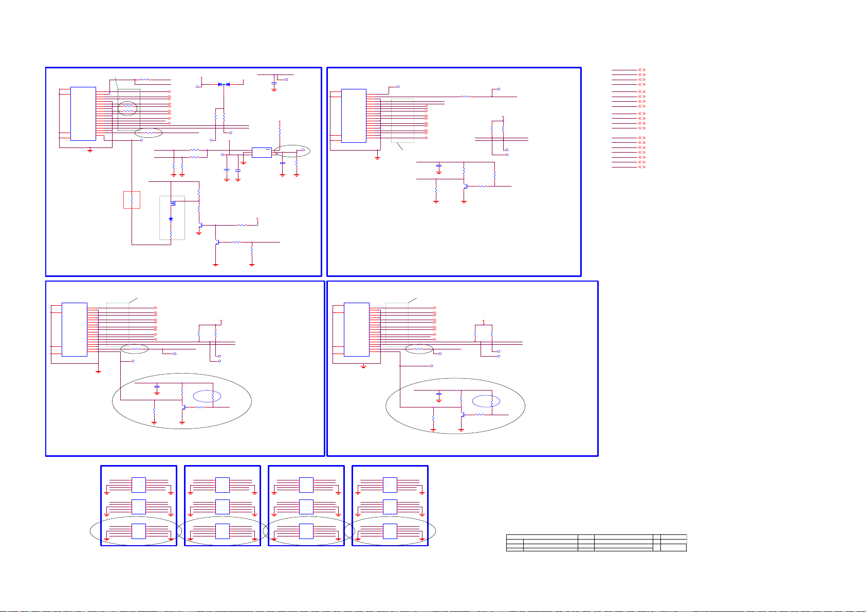
8-6-19 HDMI-INPUTS
HDMI4 Connected to RX port 0
PCB Layout for RX signals: CommonMode 30 Ohm
Differential impedance 100 Ohm
CN1308
20
SHLD0
1
TMDSD2+
SHLD2
SHLD3
SHLD1
HDMI 19P
DSHLD0
TMDSD2TMDSD1+
DSHLD1
TMDSD1TMDSD0+
DSHLD2
TMDSD0-
TMDSC +
CSHLD0
TMDSC -
DDC_GND
2
3
4
5
6
7
8
9
10
11
12
13
CEC
14
NC
15
SCL
16
SDA
17
18
VCC5
19
HPD
22
23
21
need fine tune
Use double space clearance for
HDMI0-HPD-CBUS to avoid crosstalk
Add on 2015/7/6
R7161
0R05 OHM
R7162
0R05 OHM
OPWR0_5V
HPD0
R7144
0R05 OHM
HDMI0-RX2P
HDMI0-RX2N
HDMI0-RX1P
HDMI0-RX1N
HDMI0-RX0P
HDMI0-RX0N
HDMI0-RXCP
HDMI0-RXCN
HDMI-CEC-IN
HDMI0-ARC
SCL0
SDA0
R7157
1K 1/16W
Updated on 2015/5/21
TP7326
OPWR0_5V
R7154
33R 1/16W 5%
HDMI0-HPD -CBUS
MHL-SENSE
CD-SENSE
TP7315
HDMI0-RX2P 21
HDMI0-RX2N 21
HDMI0-RX1P 21
HDMI0-RX1N 21
HDMI0-RX0P 21
HDMI0-RX0N 21
HDMI0-RXCP 21
HDMI0-RXCN 21
HDMI0-ARC 21
HDMI0-5V
Powerline for MHL = 0.5mm
13
ZD7100
BAT54
R7105
820R
0R05 OHM
NC/0R05 OHM
R7155
NC/330K +-5% 1/16W
Q7101
AO3401A
MMBT3904
MHL-PW R-EN
CD-SENSE
R7168
100K 1/16W
+5V-SW
D7105
LBAT54CWT1G
132
R7141
47K 1/16W
TP7314
+5V-SW track minimum 0.5mm
R7166
R7167
TP7312
Add on 2015/6/9
C7109
220uF 16V
R7100
10K 1/16W 5%
R7101
100R 1/16W 5%
Q7100
Q7105
MMBT3904
CD-SENSE
OPWR0_5V
100nF cap close to pin 2 of HDMI connector
R7150
47K 1/16W
HDMI0-SCL
HDMI0-SDA
TP7313
+5V-SW
U7122
1
2
G529A1TB1U
+
C7112
1uF 10V
R7102
20K 1/16W 5%
R7103
47K 1/16W 5%
CD-SENSE
C7111
100N16V
+3V3-STANDBY
R7151
10K+-5%1/16W
OPWR0_5V track minimum 0.5mm
6
EN
OC
5
OPWR0_5V
GND
OUT
4
IN3OUT
10UF 16V
+3V3-STANDBY
MHL-S ENSE
R7104
300K
HDMI0-SCL
HDMI3 Connected to RX port 1
TP7325
R7156
10K+-5%1/16W
C7105
Located at right side IO (looking from backside TV)
CN1307
21
SHLD1
23
SHLD3
22
SHLD2
20
TP7311
SHLD0
HDMI 19P
DDC_GND
TMDSC CSHLD0
TMDSC +
TMDSD0-
DSHLD2
TMDSD0+
TMDSD1-
DSHLD1
TMDSD1+
TMDSD2-
DSHLD0
TMDSD2+
HPD1
TP7324
OPWR1_5V
SDA1
SCL1
HDMI1-ARC
HDMI1-ARC 21
HDMI-CEC-IN
HDMI1-RXCN
HDMI1-RXCN 21
HDMI1-RXCP
HDMI1-RXCP 21
HDMI1-RX0N
HDMI1-RX0N 21
HDMI1-RX0P
HDMI1-RX0P 21
HDMI1-RX1N
HDMI1-RX1N 21
HDMI1-RX1P
HDMI1-RX1P 21
HDMI1-RX2N
HDMI1-RX2N 21
HDMI1-RX2P
HDMI1-RX2P 21
PCB Layout for TMDS RX signals:
Differential impedance 100 Ohm
OPWR1_5V
HPD1
R7106
100K 1/16W
C7107
100N16V
MMBT3904
R7160
1K 1/16W
R7109
1K 1/16W
Q7102
19
HPD
18
VCC5
17
16
SDA
15
SCL
14
NC
13
CEC
12
11
10
9
8
7
6
5
4
3
2
1
R7146
47K 1/16W
SCL1
SDA1
4.7K 1/16W
R7107
1K 1/16W
TP7323TP
HDMI1-5V
HDMI1-5V
R7148
47K 1/16W
HDMI1-SCL
HDMI1-SDA
TP7321
TP7322
R7108
HDMI1-HPD
HDMI1-SCL
HDMI2-SCL
HDMI3-SCL
HDMI0-SDA
HDMI1-SDA
HDMI2-SDA
HDMI3-SDA
HDMI0-HPD-CBUS
HDMI1-HPD
HDMI2-HPD
HDMI3-HPD
MHL-P WR- EN
HDMI-CEC-IN
MHL-S ENSE
HDMI0-5V
HDMI1-5V
HDMI2-5V
HDMI3-5V
HDMI0-SCL 21
HDMI1-SCL 21
HDMI2-SCL 21
HDMI3-SCL 21
HDMI0-SDA 21
HDMI1-SDA 21
HDMI2-SDA 21
HDMI3-SDA 21
HDMI0-HPD-CBUS 21
HDMI1-HPD 21
HDMI2-HPD 21
HDMI3-HPD 21
MHL-P WR- EN 19
HDMI-CEC-IN 21
MHL-S ENSE 21
HDMI0-5V 21
HDMI1-5V 21
HDMI2-5V 21
HDMI3-5V 21
HDMI2 Connected to RX port 2
Located at bottom side IO right (looking from backside TV)
CN1306
20
SHELL1
1
D2+
2
D2 Shield
SHELL3
SHELL4
SHELL2
HDMI 19P
D1 Shield
D0 Shield
CK Shield
CE Remote
DDC CLK
DDC DATA
HP DET
3
D2-
4
D1+
5
6
D1-
7
D0+
8
9
D0-
10
CK+
11
12
CK-
13
14
NC
15
16
17
GND
18
OPWR2_5V
+5V
19
HPD2
22
23
21
HDMI0 ESD
PCB Layout for TMDS RX signals:
Differential impedance 100 Ohm
HDMI2-RX2P
HDMI2-RX2N
HDMI2-RX1P
HDMI2-RX1N
HDMI2-RX0P
HDMI2-RX0N
HDMI2-RXCP
HDMI2-RXCN
HDMI-CEC-IN
HDMI2-ARC
SCL2
R7158
1K 1/16W
Updated on 2015/5/21
TP7318
OPWR2_5V
HPD2
R7112
100K 1/16W
Locate all ESD devices very close to its corresponding connector
Use for each ground pin a direct via to GND
U7120
1
HDMI0-RX2P
HDMI0-RX2N
GND
HDMI0-RX1P
HDMI0-RX1N
HDMI0-RX0P
HDMI0-RX0N
GND
HDMI0-RXCP
HDMI0-RXCN
SCL0
SDA0 SDA0
GND
OPWR0_5V
HPD0 HPD0
10
HDMI0-RX2P
CH1
NC
2
9
HDMI0-RX2N
CH2
NC
3
8
VN
VN
4
7
HDMI0-RX1P
CH3
NC
6
HDMI0-RX1N
CH45NC
NC/AOZ8804DI
U7121
1
10
HDMI0-RX0P
CH1
NC
2
9
HDMI0-RX0N
CH2
NC
3
8
VN
VN
4
7
HDMI0-RXCP
CH3
NC
6
HDMI0-RXCN
CH45NC
NC/AOZ8804DI
U7119
1
10
CH1
NC
2
9
CH2
NC
3
8
VN
VN
4
7
CH3
NC
6
CH45NC
NC/AOZ8804DI
Updated on 2015/5/21
HDMI1 Connected to RX port 3
Located at bottom side IO left (looking from backside TV)
CN1305
20
SHELL1
HDMI2-RX2P 21
HDMI2-RX2N 21
HDMI2-RX1P 21 HDMI3-RX1P 21
HDMI2-RX1N 21
HDMI2-RX0P 21
HDMI2-RX0N 21
HDMI2-RXCP 21
HDMI2-RXCN 21
HDMI2-ARC 21
HDMI2-5V
TP7317
C7106
100N16V
Q7103
MMBT3904
GND
GND
SCL0
GND
OPWR0_5V
R7110
1K 1/16W
4.7K 1/16W
R7113
1K 1/16W
HDMI1 ESD
HDMI1-RX2P
HDMI1-RX2N
GND
HDMI1-RX1P
HDMI1-RX1N
HDMI1-RX0P
HDMI1-RX0N
GND
HDMI1-RXCP
HDMI1-RXCN
SCL1
SDA1
GND
HPD1
R7149
47K 1/16W
HDMI2-5V
R7147
47K 1/16W
HDMI2-SCL
HDMI2-SDASDA2
TP7319
TP7320
R7111
Updated on 2015/5/25
HDMI2-HPD
U7124
1
10
HDMI1-RX2P
CH1
NC
2
9
HDMI1-RX2N
CH2
NC
3
8
VN
VN
4
7
HDMI1-RX1P
CH3
NC
6
HDMI1-RX1N
CH45NC
NC/AOZ8804DI
U7125
1
10
HDMI1-RX0P
CH1
NC
2
9
HDMI1-RX0N
CH2
NC
3
8
VN
VN
4
7
HDMI1-RXCP
CH3
NC
6
HDMI1-RXCN
CH45NC
NC/AOZ8804DI
U7123
1
10
CH1
NC
2
9
CH2
NC
3
8
VN
VN
4
7
CH3
NC
6
CH45NC
NC/AOZ8804DI
Updated on 2015/5/21
Updated on 2015/5/21
GND
GND
SCL1
SDA1
GND
OPWR1_5VOPWR1_5V
HPD1
HDMI2 ESD
U7114
1
HDMI2-RX2P
CH1
2
HDMI2-RX2N
CH2
3
GND
VN
4
HDMI2-RX1P
CH3
HDMI2-RX1N
CH45NC
NC/AOZ8804DI
U7115
1
HDMI2-RX0P
CH1
2
HDMI2-RX0N
CH2
3
GND
VN
4
HDMI2-RXCP
CH3
HDMI2-RXCN
CH45NC
NC/AOZ8804DI
U7113
1
SCL2
CH1
2
SDA2
CH2
3
GND
VN
4
OPWR2_5V
CH3
HPD2 HPD2
CH45NC
NC/AOZ8804DI
Updated on 2015/5/21
22
23
21
10
HDMI2-RX2P
NC
9
HDMI2-RX2N
NC
8
GND
VN
7
HDMI2-RX1P
NC
6
HDMI2-RX1N
10
HDMI2-RX0P
NC
9
HDMI2-RX0N
NC
8
GND
VN
7
HDMI2-RXCP
NC
6
HDMI2-RXCN
10
SCL2
NC
9
SDA2
NC
8
GND
VN
7
OPWR2_5V
NC
6
1
D2+
2
D2 Shield
3
D2-
SHELL3
4
D1+
5
D1 Shield
6
D1-
7
D0+
8
D0 Shield
9
D0-
10
CK+
11
CK Shield
12
CK-
13
CE Remote
14
NC
15
DDC CLK
16
DDC DATA
17
GND
SHELL4
18
+5V
19
HP DET
SHELL2
HDMI 19P
HDMI3 ESD
HDMI3-RX2P
HDMI3-RX2N
GND
HDMI3-RX1P
HDMI3-RX1N
HDMI3-RX0P
HDMI3-RX0N
GND
HDMI3-RXCP
HDMI3-RXCN
SCL3
SDA3
GND
OPWR3_5V OPWR3_5V
HPD3
Updated on 2015/5/21
U7117
1
CH1
2
CH2
3
VN
4
CH3
CH45NC
NC/AOZ8804DI
U7118
1
CH1
2
CH2
3
VN
4
CH3
CH45NC
NC/AOZ8804DI
U7116
1
CH1
2
CH2
3
VN
4
CH3
CH45NC
NC/AOZ8804DI
OPWR3_5V
HPD3
NC
NC
VN
NC
NC
NC
VN
NC
NC
NC
VN
NC
10
9
8
7
6
10
9
8
7
6
10
9
8
7
6
HPD3
HDMI3-RX2P
HDMI3-RX2N
HDMI3-RX1P
HDMI3-RX1N
HDMI3-RX0P
HDMI3-RX0N
HDMI3-RXCP
HDMI3-RXCN
HDMI3-RX2P
HDMI3-RX2N
HDMI3-RX1P
HDMI3-RX1N
HDMI3-RX0P
HDMI3-RX0N
HDMI3-RXCP
HDMI3-RXCN
HDMI-CEC -IN
HDMI3-ARC
SCL3
SDA3
R7159
1K 1/16W
OPWR3_5V
GND
GND
SCL3
SDA3
GND
HPD3
PCB Layout for TMDS RX signals:
Differential impedance 100 Ohm
HDMI3-RX2P 21
HDMI3-RX2N 21
HDMI3-RX1N 21
HDMI3-RX0P 21
HDMI3-RX0N 21
HDMI3-RXCP 21
HDMI3-RXCN 21
HDMI3-ARC 21
TP7307
Updated on 2015/5/21
TP7310
C7108
100N16V
MMBT3904
R7116
100K 1/16W
HDMI3-5V
HDMI3-5V
R7152
R7153
47K 1/16W
47K 1/16W
HDMI3-SCL
HDMI3-SDA
TP7308
TP7309
R7114
1K 1/16W
R7115
Updated on 2015/5/25
4.7K 1/16W
R7117
1K 1/16W
HDMI3-HPD
Updated on 2015/5/21
Item number in function group 7 sub-group1
T P V ( Top Victory Electronics Co . , Ltd. )
Key Component
7-HDMI-INPUTS
Date
OEM MODEL
TPV MODEL
PCB NAME
Sheet
PCB-2016-MTK-EU10 Custom
715G7772M0A0000050
of
20 25W e dne sd ay , Sept em ber 2 3, 2015
Size
Rev
Q7104
Page 97

8-6-20 HDMI-SOC-ARC
Clearance = 2 x tracewidth for all SCL and SDA
HDMI-CEC-I N CEC
HDMI-CEC-I N20
HDMI0-SCL20
HDMI1-SCL20
HDMI2-SCL20
HDMI3-SCL20
HDMI0-SDA20
HDMI1-SDA20
HDMI2-SDA20
HDMI3-SDA20
HDMI0-5V20
HDMI1-5V20
HDMI2-5V20
HDMI3-5V20
HDMI0-HPD-CBUS20
HDMI1-HPD20
HDMI2-HPD20
HDMI3-HPD20
MHL- SEN SE20
HDMI0-SCL
HDMI1-SCL
HDMI2-SCL
HDMI3-SCL
HDMI0-SDA
HDMI1-SDA +3V3-AVDD-HDMI
HDMI2-SDA
HDMI3-SDA
HDMI0-5V
HDMI1-5V
HDMI2-5V
HDMI3-5V
HDMI0-HPD-CBUS
HDMI1-HPD
HDMI2-HPD
HDMI3-HPD
MHL- SEN SE
R7214
NC/10K+-5%1/16W
R7200
100OHM1/16W
+1V0-AVDD-HDMI
+1V0-AVDD-HDMI
+3V3-AVDD-HDMI
U9400-6
G24
HDMI_CEC
F26
HDMI_0_SCL
G30
HDMI_1_SCL
G31
HDMI_2_SCL
D34
HDMI_3_SCL
F27
HDMI_0_SDA
G28
HDMI_1_SDA
F33
HDMI_2_SDA
D33
HDMI_3_SDA
G26
HDMI_0_PWR5V
E30
HDMI_1_PWR5V
E31
HDMI_2_PWR5V
E34
HDMI_3_PWR5V
F28
HDMI_0_HPD_C BU S
F30
HDMI_1_HPD
F31
HDMI_2_HPD
F34
HDMI_3_HPD
F24
MHL_SENSE
B30
AVDD10_HDMI
A30
AVDD10_HDMI
P27
AVDD33_HDMI
P28
AVDD33_HDMI
MT5593UGIJ
HDMI_0_RX_0
HDMI_0_RX_0B
HDMI_0_RX_1
HDMI_0_RX_1B
HDMI_0_RX_2
HDMI_0_RX_2B
HDMI_0_RX_C
HDMI_0_RX_CB
HDMI_1_RX_0
HDMI_1_RX_0B
HDMI_1_RX_1
HDMI_1_RX_1B
HDMI_1_RX_2
HDMI_1_RX_2B
HDMI_1_RX_C
HDMI_1_RX_CB
HDMI_2_RX_0
HDMI_2_RX_0B
HDMI_2_RX_1
HDMI_2_RX_1B
HDMI_2_RX_2
HDMI_2_RX_2B
HDMI_2_RX_C
HDMI_2_RX_CB
HDMI_3_RX_0
HDMI_3_RX_0B
HDMI_3_RX_1
HDMI_3_RX_1B
HDMI_3_RX_2
HDMI_3_RX_2B
HDMI_3_RX_C
HDMI_3_RX_CB
HDMI TMDS signals
Differential 100 Ohm nets
A20
B20
A19
B19
A18
B18
A21
B21
C23
D23
C22
D22
A22
B22
A24
B24
A26
B26
C25
D25
C24
D24
C26
D26
C28
D28
A28
B28
C27
D27
C29
D29
HDMI0-RX0P 20
HDMI0-RX0N 20
HDMI0-RX1P 20
HDMI0-RX1N 20
HDMI0-RX2P 20
HDMI0-RX2N 20
HDMI0-RXCP 20
HDMI0-RXCN 20
HDMI1-RX0P 20
HDMI1-RX0N 20
HDMI1-RX1P 20
HDMI1-RX1N 20
HDMI1-RX2P 20
HDMI1-RX2N 20
HDMI1-RXCP 20
HDMI1-RXCN 20
HDMI2-RX0P 20
HDMI2-RX0N 20
HDMI2-RX1P 20
HDMI2-RX1N 20
HDMI2-RX2P 20
HDMI2-RX2N 20
HDMI2-RXCP 20
HDMI2-RXCN 20
HDMI3-RX0P 20
HDMI3-RX0N 20
HDMI3-RX1P 20
HDMI3-RX1N 20
HDMI3-RX2P 20
HDMI3-RX2N 20
HDMI3-RXCP 20
HDMI3-RXCN 20
MT5593 Por t0 = HDMI/MHL input
MT5593 Por t3 = HDMI 2.0 input
Analog Power
+5V-SW
R7202
1K 1/16W 5%
Updated on 2015/5/21
+3V3-AVDD
C7211
NC/10NF 50V
+1V0-AVD D
Q7106
AO3414
TP7425
C7202
100N16V
Prevent HDMI leakage from HDMI device.
R7201
100K 1/16W 5%
+1V0-AVDD-HDMI
C7200
100N16V
C7201
NC/1uF 10V
HDMI-ARC-SEL1
HDMI-ARC-SEL0
ARC
Schield ARC
HDMI-ARC-SEL1 19
HDMI-ARC-SEL0 19
ARC 22
TP7428
TP7426
TP7429
HDMI1-ARC20
C7206
10PF 50V
TP7419
R7203
100R 1/16W 1%
ARC0
ARC3
R7212
100R 1/16W 1%
FB7200
1 2
120R
HDMI2-ARC20
C7207
10PF 50V
TP7420
TP7423
+3V3
ARC2
ARC1
HDMI-ARC-SEL0
HDMI-ARC-SEL1
TP7424
R7209
NC/1 0K+-5%1/16W
FB7201
1 2
120R
HDMI3-ARC20
C7208
10PF 50V
C7205
1uF 10V
TP7421
R7206
100R 1/16W 1%
TP7427
R7211
100R 1/16W 1%
HDMI0-ARC20
Each individual filter close to corresponding HDMI con necto r
HDMIx-ARC schield as much as possible with ground trac ks
+5V-SW
16
15
14
13
12
11
10
9
FB7202
1 2
120R
U7201
VCC
Y2
Y1
Y0
Y3
S0
S1
S2
74HC4051PW
R7213
0R05 OHM
1 2
C7209
10PF 50V
1
Y4
2
Y6
3
Z
4
Y7
5
Y5
6
E
7
VEE
8
GND
Schield these nets in layout
ARC0
ARC1
ARC2
FB7203
ARC3
120R
TP7422
1uF 10V
R7204
100R 1/16W 1%
ARC-BUFF
Updated on 2015/9/3
TP74 17
R7205
56R 1/16W 5%
HDMI-ARC-SEL0
HDMI-ARC-SEL1
TP7416
R7208
180R 1/16W 1%
R7215
NC/1 0K+-5%1/16W
Audi o Return Ch annel (ARC)
R7207
56R 1/16W 5%
L
L
H
+3V3C7204
C7210
100N16V
U7202
5
VCC
4
SN74LVC1G125DCKR
R7210
NC/0R05 OHM
HDMI-ARC-SEL0HDMI-ARC-SEL1
R7216
NC/10K+-5%1/16W
pin1 Low = enable
1
OE
2
A
GND3Y
L
H
L
HH
ARC
Schield ARC
Output
HDMI0
HDMI1
HDMI2
HDMI3
TP7418
Page 98

8-6-21 SCART-YPbPr-CVBS
3
4
1
2
TP7506
SCART-AUDIO-R
SCART-AUDIO-L
NC/AZ 5125-01H.R7G
ZD7500
1 2
12
ZD7501
NC/AZ 5125-01H.R7G
CN1310
PHONE JACK 4P
5
4
3
2
1
TP7507
DVI-AU DIO- IN (T O P )
CN1317
NC/AUDIO ANALOG IN JACK
2
3
1
TP7534
TP7537
DVI-AUDIO- IN (SIDE)
AUDIO - MO DU LE - S PDIF O UT (SIDE )
+3V3
debug
C7545
NC/470PF 50V
C7549
NC/470PF 50V
10000pF 50V
S7500
SPG_0001-0015
TP7524
1 2
TP7503
S7501
SPG_0001-0015
1 2
S7502
SPG_0001-0015
TP7504
1 2
TP7505
12
S7503
SPG_0001-0015
S7512
SPG_0001-0015
TP7532
1 2
TP7533
12
S7513
SPG_0001-0015
I2C-signals double space
where possible GND shield
R7535 2.2K 1/16W
R7539 2.2K 1/16W
add text
I2C-FE
R7552
NC/4.7K 1/16W
R7555
30Kohm 1/16W +/-5%
R7557
30Kohm 1/16W +/-5%
R7558
NC/4. 7K 1/ 16W
C7500
C7505
10000pF 50V
10000pF 50V
C7511
C7512
10000pF 50V
NC/10000pF 50V
C7556
C7557
NC/10000pF 50V
AUDIO-MODULE-PAIRED
R7570
NC/0R05 OHM
C7559
NC/10000pF 50V
SCL-FE
SDA-FE
CN1022
45
NC/CONN 3P
1
2
3
Stuff on 2015/07/24
C7546
1UF16V
1UF16V
C7547
C7502
1UF16V
C7503
1UF16V
1UF16V
C7508
1UF16V
C7513
TP7508
C7570NC/1UF16V
TP7509
SCART-CVBS-I N
10000pF 50V
10000pF 50V
C7571NC/1UF16V
C7543
C7551
CN1309
B
A
1. Add ground shielding for all SCART and
YPBPR and DVI signals of Audio & Video.
NC/4. 7K 1/ 16W
C7501
NC/470PF 50V
R7500
R7503
C7504
NC/470PF 5 0V
NC/4. 7K 1/ 16W
Close to SoC
NC/4.7K 1/16W
R7504
R7514
NC/4.7K 1/16W
FB7318
1 2
AUDIO-MOD ULE-SPDI F
NC/30R
AUDIO-MODULE-DETECT
R7571
NC/0R05 OHM
ADCINP_DEMOD
ADCINN_DEMOD
NC/47pF 50V
IF_AGC_5593
C7525
C7529
47N16V
75OHM 1/16W
1 2
12
S7509
10K+-5%1/16W
R7543
S7507
SCART-STATUS
0R05 OHM
0R05 OHM
C7526
NC/47pF 50V
R7530
75 OHM +-1% 1/16W
R7501
30Kohm 1/16W +/ -5%
R7502
30Kohm 1/16W +/ -5%
NC/470PF 50V
C7506
R7505
30Kohm 1/16W +/ -5%
R7512
30Kohm 1/16W +/ -5%
C7514
NC/470PF 50V
R7524
R7527
C7534
R7547
47pF 50V
100OHM1/16W
R7560
51K 1/16W 5%
R7563
10K+-5%1/16W
R7565
SCART-FB
10OHM1/16W
SCART-AUD IO-R
SCART-AUD IO-L
+3V3-AVDD
VMID-AADC
C7515
100N16V
RF_AGC
R7537 10OHM1/16W
R7540 10OHM1/16W
1UF16V
C7532
47N16V
C7538
12
S7516
updated on 2015/5/11
TP7519
12
S7515
R7566
SPG_0001-0015
1. Add ground shielding
for all SCART and YPBPR
and DVI signals of Audio
& Video.
U9400-4
B36
YPBPR-AUDIO-R
YPBPR-AUDIO-L
DVI-AUDIO-R
DVI-AUDIO-L
C7509
100N16V
C7516
1UF 6.3V
D37
A37
C38
B38
B35
A36
C37
M26
D38
M24
AIN_R0
AIN_L0
AIN_R1
AIN_L1
AIN_R2
AIN_L2
AIN_R3
AIN_L3
AVDD33_AADC
VMID_AADC
AVSS33_CLN
MT5593UGIJ
AR0_ADAC
AL0_ADAC
AR1_ADAC
AL1_ADAC
AR2_ADAC
AL2_ADAC
AVDD33_ADAC
ASPDIFI
ASPDIFO0
ASPDIFO1
AOBCK
AOLRCK
AOMCLK
AOSDATA4
AOSDATA3
AOSDATA2
AOSDATA1
AOSDATA0
Add on 2015/9/5 for EMI
U9400-5
F38
TER-I Fp-AN A
TER-I Fn-AN A
TP7500
TP7501
AGC-ANA
TP7502
SCART-CVBS
TP7516
TP7517
TP7518
SPG_0001-0015
TP7523
NC/AZ 5125-01H.R7G
SCART-AUDIO-R-IN
SCART-AUDIO-L-IN
SCART-FS-IN
SCART-FB-I N
SCART-CVBS-I N
12
S7514
SPG_0001-0015
F37
L26
L27
B14
C15
E18
F18
J36
J38
K35
K34
H38
H37
ZD7505
ZD7507
NC/RLZ13B
ADCINP_DEMOD
ADCINN_DEMOD
LOUTP
LOUTN
IF_AGC
RF_AGC
OSCL2
OSDA2
CVBS_COM
CVBS3P
CVBS2P
CVBS1P
CVBS0P
SIF_COM
MT5593UGIJ
1 2
AVDD33_VID EO_STB
AVDD33_XTAL_STB
AVDD33_DEMOD_STB
AVSS33_DEMOD
NC/AZ 5125-01H.R7G
ZD7506
1 2
1 2
ZD7508
NC/TVM1G5R5M100R
1 2
ZD7509
NC/TVM1G5R5M100R
1 2
HSYNC
VSYNC
VGA_SDA
VGA_SCL
COM1
PR1P
SOY1
COM0
PR0P
SOY0
VDACX_OUT
AVSS33_XTAL
TP7514
RP
GP
BP
COM
SOG
PB1P
Y1P
PB0P
Y0P
D36
C35
D35
E36
C36
E35
M27
AR38
AB34
G27
AM31
AN30
AP36
AN33
AM33
AL31
AM30
AN31
R37
T36
N37
P37
R38
P36
P38
U36
T37
M38
M36
L38
M37
N36
K37
K36
J37
L36
L37
K33
M35
G37
G38
N25
N24
10
12
14
16
18
20
CN1312
SCART 21P
2
4
6
8
AUDIO-HP-R
AUDIO-HP-L
AUDIO-HTV-R
AUDIO-HTV-L
C7507
100N16V
R7511 47 OHM 1/16W
R7573 47 OHM 1/16W
R7513 47 OHM 1/16W
R7515 47 OHM 1/16W
R7516 47 OHM 1/16W
R7517 47 OHM 1/16W
R7518 47 OHM 1/16W
R7519 47 OHM 1/16W
R7520 47 OHM 1/16W
1 2
FB7500
NC/120R
SCART-COM
SCART-G
SCART-R
SCART-B
SCART-FB
TUNER-BYPASS-OUT
+3V3-STANDBY
C7539
100N16V
1
3
5
7
9
11
13
15
17
19
21
+3V3-AVDD
C7510
10UF 6.3V X5R +-20%
C7517
NC/47pF 50V
Add on 2015/9/5 for EMI
R7572 10OHM1/16W
+3V3-STANDBY
C7536
C7535
100N16V
1uF 10V
SPG_0001-0015
TP7520
SCART-B-IN
TP7521
SCART-G-IN
TP7522
SCART-R-IN
SPG_0001-0015
SPG_0001-0015
C7521
NC/47pF 50V
C7522
NC/47pF 50V
TP7535
R7544
75OHM 1/16W
TP7536
S7508
S7510
S7511
AUDIO-MODULE-SPDIF
AUDIO-MODULE-DETECT
AUDIO-MODULE-PAIRED
SPDIF-OUT
ARC
C7524
C7518
C7519
C7523
18PF 50V
NC/47pF 50V
NC/47pF 50V
1 2
1 2
1 2
1 2
1 2
1 2
C7558
33P50V
NC/47pF 50V
YPBPR-PR
YPBPR-PB
YPBPR-COM
YPBPR-Y
YPBPR-SOY
YPBPR-CVBS
ZD7502
NC/TVM1G5R5M100R
ZD7503
NC/TVM1G5R5M100R
ZD7504
NC/TVM1G5R5M100R
C7520
47pF 50V
Close to SoC
C7542 10000pF 50V
C7537 10000pF 50V
C7533 10000pF 50V
C7530 10000pF 50V
C7528 1.5NF 50V
C7527 47N16V
R7553
0R05 OHM
R7561
0R05 OHM
R7568
0R05 OHM
R7507
R7521
R7556
R7564
R7567
R7506
NC/10K+-5%1/ 16W
R7525
NC/100K 1/ 16W
100OHM1/16W
100OHM1/16W
100OHM1/16W
100OHM1/16W
100OHM1/16W
75OHM 1/16W
75OHM 1/16W
75OHM 1/16W
NC/10K+-5%1/ 16W
NC/100K 1/ 16W
R7550
R7545
R7541
R7533
R7528
C7548
10PF 50V
C7553
10PF 50V
C7554
10PF 50V
AUDIO-MODULE-SPDIF 18
AUDIO-MODULE-DETECT 19
AUDIO-MODULE-PAIRED 19
+3V3
R7508
R7509
R7510
NC/10K+-5%1/ 16W
NC/10K+-5%1/ 16W
R7526
R7522
R7523
NC/100K 1/ 16W
NC/100K 1/ 16W
10PF 50V
C7541
10PF 50V
C7540
R75420R05 OHM
10PF 50V
C7531
R7554100OH M1/16W
R7559 100OH M1/16W
R7562 100OH M1/16W
R7569100OHM1/16W
NC/10K+-5%1/ 16W
NC/100K 1/ 16W
SOC-I2S-SD017, 18,24
SOC-I2S-SD118,24
SOC-I2S-SD218,24
SCL-FE6
SDA-FE6
YPBPR-DETECT19
SOC-I2S-BCLK17,18,24
SOC-I2S-LRCK17,18, 24
SOC-I2S-MCLK17,18,24
AUDIO-HTV-L25
AUDIO-HTV-R25
TP7525
TP7526
TP7527
TP7528
TP7529
TP7530
TP7531
Updated on 2015/5/18
updated on 2015/5/11
0R05 OHM
R7551
75OHM 1/16W
R7549
75OHM 1/16W
R7548
0R05 OHM
R7546
updated on 2015/5/11
75OHM 1/16W
R7536
0R05 OHM
R7531
10OHM1/16W
R7529
C7544 10000pF 50V
C7550 10000pF 50V
C7552 10000pF 50V
C7555 10000pF 50V
SOC-I2S-SD 0
SOC-I2S-SD 1
SOC-I2S-SD 2
SOC-I2S-SD3
SOC-I2S-SD 318
1 2
1 2
1 2
YPBPR-DETECT
ZD7510
NC/TVM1G5R5M100R
ZD7511
NC/TVM1G5R5M100R
ZD7512
NC/TVM1G5R5M100R
SCL-FE
SDA-FE
SOC-I2S-BCLK
SOC-I2S-LR CK
SOC-I2S-MCLK
AUDIO-HTV-L
AUDIO-HTV-R
SOC-I2S-BCLK
SOC-I2S-LRCK
SOC-I2S-MCLK
SOC-I2S-SD3
SOC-I2S-SD2
SOC-I2S-SD1
SOC-I2S-SD0
SPG_0001-0015
S7506
SPG_0001-0015
S7505
SPG_0001-0015
S7504
updated on 2015/5/11
1. Add ground shielding
for all SCART and YPBPR
and DVI signals of Audio
& Video.
SCART-B
SCART-COM
SCART-G
SCART-R
IF_AGC_55936
SPDIF-OUT17
ADCINP_DEMOD6
ADCINN_D EMOD6
SCART-STATUS19
AUDIO-HP-R17
AUDIO-HP-L17
Close to connector
12
PR-IN-0
12
PB-IN-0
Y-IN-0
12
IF_AGC_5593
SPDIF-OUT
ADCINP_DEMOD
ADCINN_DEMOD
RF_AGC
RF_AGC6
ARC
ARC21
SCART-STATUS
AUDIO-HP-R
AUDIO-HP-L
TP7515
RCA JACK
6
C
TP7513
NC/0R05 OHM
R7538
10K+-5%1/16W
R7534
7
4
5
1
2
3
CN1311
LBC847BWT1G
Q7500
10K+-5%1/16W
R7532
+3V3-AVDD
B
A
YPBPR-DETECT
TP7510
TP7511
TP7512
Page 99

8-6-22 CTRL-CONNECTORS
1415
TP8411
RC-IR
R8406 100OHM1/16W
RC-HTV
CN1106
1
2
3
4
5
6
7
8
9
10
11
12
13
COMM
AL+KEY
TP8400
TP8401
TP8402
TP8403
TP8404
TP8405
TP8406
TP8407
TP8408
TP8409
TP8410
+3V3-STANDBY
R8440
10K+-5%1/16W
AMBI-POWER
NC/CONN
W o rd mark Driver
R8413
NC/10K+-5%1/16W
R8415
NC/0R05 OHM
R8417
NC/10K+-5%1/16W
LED2
LED1
1112
CN1107
1
2
3
4
5
6
7
8
9
10
C8416
+3V3-STANDBY
R8414
NC/10K+-5%1/16W
Q8401
NC/LBC847BWT1G
AMBI-POWER
C8415
100N16V
22uF 25V
R8416
NC/10K+-5%1/16W
R8420
0R05 OHM
C8412
C8413
NC/1uF 10V
NC/10U F 6. 3V X5R +-20%
R8423
Q8400
NC/LBC847BWT1G
R8404 100OHM1/16W
R8405 100OHM1/16W
R8402 0R05 OHM
C8400
100pF 50V
12
TH8407
NC/PTCR
t
100pF 50V
C8409
+3V3
R8424
R8430
R8429
0R05 OHM
0R05 OHM
R8411 NC/100OH M1/16W
NC/0R 05 OH M
NC/0R 05 OH M
+3V3-STANDBY
R8401
6K8 1%
R8418 47 OHM 1/16W
R8419 47 OHM 1/16W
R8431 NC/10OHM
R8410 100OHM1/16W
R8432 NC/10OHM
NC/100pF
100pF 50V
C8408
C8407
10PF 50V
100pF 50V
C8403
C8405
KEYBOARD
AMBI-SPI-CLK
AMBI-SPI-MOSI
SCL-AMBI
AMBI-TEMP
SDA-AMBI
1uF 10V
C8411
+3V3-STANDBY
TO SENSOR BOARD (CIP)
LED1, LED2:
Enable: High
Disable: Low
LED2 is wordmark
+3V3-STANDBY
100N 50V
Add on 2015/10/20
100pF 50V
C8404
C8402
KEYBOARD
R8403
NC/10OHM
Debug IR receiver
R8001 NC/100OHM1/16W
RC-IR
R8002 NC/10OHM1/16W
RC-HTV
R8003 NC/10OHM1/16W
SCL-SET
R8407 10OHM1/16W
SDA-SET
C8401
NC/100pF 50V
R8408 10OHM1/16W
AMBI-SPI-CLK
AMBI-SPI-MOSI
AMBI-TEMP
SCL-AMBI
SDA-AMBI
SOC-CTRL-DISP1
KEYBOARD
RC-IR
NT-3D-IR
SOC-3D-IR
SDA-SET
SCL-SET
SOC-RX-SERVICE
SOC-TX-SERVICE
LED1
LED2
AUDIO-RESETn
U8000
1
GND
2
Vs
3
OUT
4
GND
C8001
C8002
C8003
NC/1uF 10V
NC/10PF 50V
+12V
C8417
C8418
10PF 50V
10PF 50V
NC/100N 16V
F8202
1 2
T 2A 63V
C8419
NC/10U F 16V
NC/TSOP75236TT
TP8412
TP8413
TP8414
TP8416
TP8415
TP8417
TP8418
TP8419
TP8420
TCON -LR
NT-3D-IR
SOC-3D-I R
11
13
15
17
R8409 10OHM1/16W
R8412 NC/10OHM
1
3
5
7
9
CN1108
CONN
AUDIO-HTV-L
AUDIO-HTV-R
STANDBY
RC-HTV
TCON -LR
2
4
6
8
10
12
14
16
18
TP8421
TP8422
AMBI-SPI-CLK 8
AMBI-SPI-MOSI 8
AMBI-TEMP 19
SCL-AMBI 8
SDA-AMBI 8
SOC-CTRL-DISP1 7
KEYBOARD 19
RC-IR 2,18,25
NT-3D-IR 7,8,18
SOC-3D-IR 18,19
SDA-SET 2
SCL-SET 2
SOC-RX-SERVICE 2,25
SOC-TX-SERVICE 2,25
LED1 19
LED2 19,24
AUDIO-RESETn 17,18,19,25
AUDIO-HTV-L 22,25
AUDIO-HTV-R 22,25
STANDBY 2,15
RC-HTV 25
TCON -LR 9
TH8205
PTCR
t
1 2
Updated footprint on 2015/9 /2
C8406
100pF 50V
+3V3
Add on 2015/8/18
Page 100

8-6-23 CTRL-ETHERNET-PHY
U9400-10
MT5593UGIJ
R8257
LAN-PWR-EN
4.7K 1/16W
C4462
47N16V
R8249
22K 1/16W
TP8221
R8252
100K 1/16W
Change 2015/01/27
TXVP_0
TXVN_0
RXVP_1
RXVN_1
PHYLED1
PHYLED0
AVDD33_ETH
LBC847BWT1G
R8251
47K 1/16W
REXT
TP8220
NC/0R05 OHM
Q8203
TP8216
TP8217
R8211
W37
W38
Y37
Y38
AA34
AB35
V38
P29
C8247
C8249
100N16V
ETHERNET-TXp
ETHERNET-TXn
ETHERNET-RXp
ETHERNET-RXn
REXT
+3V5-SB
22UF 6.3V
C8248
+3V3-LAN
RT9187GSP
U8203
1
VIN
2
VIN
3
VOUT
VOUT4BP/ADJ
R8250
68K 1/16W 1%
R8253
NC/1M 1/16W
TP8219
22UF 6.3V
Close to Main Chip
ETHERNET PHY
+3V3-LAN
TP8218
9
GND
8
EN
7
NC
6
GND
5
22K 1/16W
470KOHM 5% 1/16W
FB8200
1 2
120R 3A
R8203
24K1/16W
LAN-PWR-EN
R8254
NC/4. 7K 1/ 16 W
R8256
R8255
TP8222
C8235NC/10000pF 50V
CS1 C ON2SIG050
1 2
TO CHASSIS-GND
C8207
NC/10000pF 50V
CN1313
RJ45 8P
1
2
3
4
5
6
7
8
P1
P2
P3
P4
P5
P6
P7 NC
P8
Must be differential 100ohm
TP8204
RJ45
C8200
C8201
10000pF 50V
100N16V
ETHERNET-TXp
ETHERNET-TXn
ETHERNET-RXp
ETHERNET-RXn
C8202
C8203
100N16V
10000pF 50V
Add on 2015/07/24
NC/1uF 25V
Must be differential 100ohm
Replacement for ESD protection device IP4294CZ10-TBR
+3V3-LAN
TP8210
TP8211
TP8212
TP8213
ETHERNET-TXp
ETHERNET-TXn
ETHERNET-RXp
ETHERNET-RXn
Updated on 2015/5/21
TP8205
C8204
U8201
1
CH1
2
CH2
3
VN
4
CH3
CH45NC
NC/AOZ8804DI
388G342H8B2VGN
C8208NC/10000pF 50V
C8205
NC/10000pF 50V
10
NC
9
NC
8
VN
7
NC
6
C8214NC/10000pF 50V
ETHERNET-TXp
ETHERNET-TXn
ETHERNET-RXp
ETHERNET-RXn
C8218NC/10000pF 50V
C8206
NC/1uF 25V
SEPARATE GROUND
Place close to RJ45 connector on Top layer
updated on 2015/5/11
P/N : 388G342G8B4AGN
9
TH1
TH2
10
R8245
0R05 OHM
+3V3-USB Power
+3V3
+5V-SW
R8239
1K 1/16W
C8240
NC/10000pF 50V
TP8455
910
CN1110
1
2
3
4
5
6
7
8
WIFI-RESET
CONN
Prevent USB leakage from WIFI module
R8238 NC/0R05 OHM
Q8201
AO3414
Use wide track 0.5mm for local +3V3 and +3V3-USB
Position FET close to Soc AVDD33_USB/AVDD33SS_USB pins
R8240
Also 100nF close to Soc pins
100K 1/16W
+3V3-WI FI
R8200 NC / 2R 2 +-5% 1/16W
L8201
TP8446
TP8440
TP8441
R8201 NC / 2R 2 +-5% 1/16W
TP8442
TP8443 TP8208
TP8444
10OHM1/16W
R8204
R8209
NC/0R05 OHM
NC/10K+-5% 1/16W
TP8215
+3V3-USB
Wi-Fi Control
3
142
90OHM
R8202 0R05 OHM
BT-IRQn
TP8209
R8210
R8207
10K+-5%1/16W
+3V3-WIF I
C8239
100N16V
Updated on 2015/07/24
USB-WIFI-D n
USB-WIFI-D p
WIFI-IRQn
R8206
NC/10K+-5% 1/16W
+3V3-WI FI
TP8206
TP8207
R8208
10K+-5%1/16W
Optional circuit
for WIFI-RESET
Updated on 2015/5/18
TP6125
WIFI-RESETn7
LAN-PWR-EN
WIFI-IRQn
BT-IRQn
USB-RESETn
SOC-I2S-MCL K
SOC-I2S-SD0
SOC-I2S-SD1
SOC-I2S-SD2
SOC-I2S-LRCK
SOC-I2S-BCLK
LED2
Place onlocation with space
+3V3-WI FI
R8247
10K+-5%1/16W
TP6122
R8246
0R05 OHM
32
R1
1
Q8202
NC/LMUN5211T1G
R2
LAN-PWR-EN 19
WIFI-IRQn 19
BT-IRQn 19
USB-RESETn 19
SOC-I2S-MCLK 17,18,22
SOC-I2S-SD0 17,18,22
SOC-I2S-SD1 18,22
SOC-I2S-SD2 18,22
SOC-I2S-LRCK 17,18,22
SOC-I2S-BCLK 17,18,22
LED2 19,23
Updated on 2015/5/18
WIFI-RESET
R8248
0R05 OHM
C8241
10000pF 50V
TP6124
USB
U9400-9
MT5593UGIJ
USB_DP_P0
USB_DM_P0
USB_DP_P1
USB_DM_P1
USB_DP_P2
USB_DM_P2
USB_DP_P3
USB_DM_P3
SSUSB_TXP
SSUSB_TXN
SSUSB_RXP
SSUSB_RXN
SSUSB_VRT
AVDD33_USB
AVDD33_SSUSB
AVDD10_SSUSB
USB_VRT_P0
+5V-SW
A16
B16
A17
B17
C31
D31
AA37
AA38
B34
A34
B32
A32
A35
N28
A33
A31
B15
5K1 1/16W 5%
+
TP8461
TP8462
TP8463
TP8464
TP8465
TP8466
TP8467
TP8468
USB-SS-TXp
USB-SS-TXn
USB-SS-RXp
USB-SS-RXn
USB-SS-VRT
+3V3-USB
+3V3-USB
+1V0-USB-SS
USB-VRT-P0
R8219
+1V0-AVDD
C8210
100UF 16V
USB-HUB-Dp
USB-HUB-Dn
USB-EXT2-Dp
USB-EXT2-Dn
USB-WIFI-Dp
USB-WIFI-Dn
C8228
1UF 6.3V
NEAR USB PORTS
C9445
NC/10UF 16V
EQUAL LENGTH and
DIFFERENTIAL
IMPEDANCE 90ohm
R8234 0R05 OHM
R8235 0R05 OHM
R8242 NC /0R 05 OHM
R8241 NC /0R 05 OHM
R8236 0R05 OHM
R8237 0R05 OHM
USB-EXT1-J-Dn
USB-EXT1-J-Dp
C8222
1UF 6.3V
+3V3-USB
C8225
C8224
100N16V
1UF 6.3V
NEAR SOC
C8229
100N16V
R8243 0R05 OHM
R8244 0R05 OHM
Near SOC
C8223
NC/100N16V
Near SOC
USB-EXT0-Dp
USB-EXT0-Dn
USB-CAMERA-Dp
USB-CAMERA-Dn
USB-EXT1-J-Dp
USB-EXT1-J-Dn
R8217
USB-EXT1-Dn
USB-EXT1-Dp
5K1 1/16W 5%
+5V-SW
1 2
TH8202 PTCR
current 750mA
USB HUB
EQUAL LENGTH and
DIFFERENTIAL
IMPEDANCE 90ohm
C8244
NC/100N16V
+3V3
+5V-SW
1 2
TH8201 PTCR
current 750mA
t
C8245
NC/100N16V
+3V3
USB PORT 0
USB-EXT0-Dp
USB-EXT0-Dn
t
USB PORT 1
USB-EXT1-Dp
USB-EXT1-Dn
C8226
NC/100N16V
USB-HUB-Dn
TP8475
USB-HUB-Dp
TP8476
USB-EXT0-Dn
USB-EXT0-Dp
USB-EXT1-Dn
USB-EXT1-Dp
R8232
NC/680R 1/16W 5%
C8232
NC/18pF 50V
C8233
NC/18pF 50V
TP8451
TP8452
C8236
100N16V
EQUAL LENGTH and
DIFFERENTIAL
IMPEDANCE 90ohm
TP8449
R8221 2R2 +-5% 1/16W
TP8450
R8222 2R2 +-5% 1/16W
C8237
100N16V
NC/10PF 50V
CU3/CU4 is reserved
for performance .
+3V3
1
DM0
2
DP0
3
DM1
4
DP1
5
AVDD
6
DM2
7
DP2
TP8474
1
X820 0
NC/12MHZ
24
3
EQUAL LENGTH and
DIFFERENTIAL
IMPEDANCE 90ohm
R8215 2R2 +-5% 1/16W
R8216 2R2 +-5% 1/16W
C8212
NC/10PF 50V
CU3/CU4 is reserved
for performance .
C8220
R8225
R8226
TP8477
TP8480
NC/10K+-5%1/16W
NC/10K+-5%1/16W
TP8479
28
24
27
22
26
23
V5
V33
SDA
PSELF
21
PGANG
DVDD
20
OVCUR1#25OVCUR2#
OVCUR3#
19
OVCUR4#
18
TEST/SCL
17
RESET#
16
DP4
15
DM4
RREF8AVDD9XTAL110XTAL211DM312DP313AVDD
P
U8202
NC/GL850G-OHG
14
29
Updated on 2015/6/5
EQUAL LENGTH and
USB-EXT0-Dp-R
USB-EXT0-Dn-R
C8211
NC/10PF 50V
TP8437
TP8438
TP8439
USB PORT 2
USB CONN
CN1314
USB3.0
65
4
3
2
1234
1
TP8445
TP8447
TP8448
USB-EXT2-Dp-R
USB-EXT2-Dn-R
C8215
NC/10PF 50V
DIFFERENTIAL
IMPEDANCE 90ohm
R8213 2R2 +-5% 1/16W
R8214 2R2 +-5% 1/16W
C8213
10UF 6.3V 20%
C8216
NC/10PF 50V
Updated 18AC on 2015/6/4
5
RXN
6
USB3.0
RXP
7
GND
USB2.0
8
TXN
9
TXP
EQUAL LENGTH and
DIFFERENTIAL
IMPEDANCE 90ohm
C8227
NC/100N16V
F8200 NC/T 2A 63V
1 2
R8437 NC/0R05 OHM
Updated 18AC on 2015/6/4
USB-SS-RXn-R
USB-SS-RXp-R
USB-SS-TXp-R
+3V3
SOC-I2S-MCL K
SOC-I2S-LRCK
SOC-I2S-BCLK
C8231
NC/100N16V
LED2
+3V3-STANDBY
CN1316
1
VCC
2
D-
3
D+
4
GND
10
HAND1
11
HAND2
USB CONN 9P
R8229
NC/10OHM1/16W
+12V
R8433 NC / 0R05 OH M
R8434 NC / 0R05 OH M
R8435 NC / 0R05 OH M
Add on 2015/7/14 for CTV need
USB-EXT1-Dp-R
R8260 0R05 1/16W
USB-EXT1-Dn-R USB-SS-TXn-R
R8261 0R05 1/16W
C8221
NC/10PF 50V
Updated 18AC on 2015/6/4
R8258 NC/0R05 1/16W
R8259 NC/0R05 1/16W
65
4
3
2
USB CONN
1234
1
CN1315
65
4
3
2
NC/USB CONN
1234
1
CN1320
USB CAMERA
Add on 2015/7/14 for HTV need
SOC-I2S-SD0
SOC-I2S-SD1
SOC-I2S-SD2
USB-RESETn
TP8478
R8228
NC/10K+-5%1/16W
C8243
NC/100N16V
TP8469
TP8470
TP8471
C8246
NC/100N16V
+3V3
+3V3
R8227
NC/100K 1/16W
+3V3
+3V3
R8230 NC/ 10K+-5%1/16W
R8231 NC/ 10K+-5%1/16W
C8234
NC/100N16V
+3V3
+3V3
+3V3
R8233
NC/10K+-5% 1/16W
R8436
NC/0R05 OHM
C8209
10UF 6.3V 20%
USB-CAMERA-Dn
USB-CAMERA-Dp
C8230
NC/100N16V
USB-EXT2-Dp
TP8453
USB-EXT2-Dn
TP8454
C8238
100N16V
R8439 NC / 0R 05 OH M
R8441 NC / 0R 05 OH M
R8442 NC / 0R 05 OH M
Add on 2015/6/9
TH8203
1 2
PTCR
current 900mA
C8217
100N16V
C8219
100N16V
+5V-SW
t
R8218 0R05 OHM
R8220 0R05 OHM
0R05 OHM
R8223
R8224
0R05 OHM
CN1111
TP8423
TP8424
TP8425
TP8426
TP8427
TP8428
TP8429
TP8431
NC/CONN
USB-EXT2-Dn-R
USB-EXT2-Dp-R
USB-SS-RXn-R
USB-SS-RXp-R
USB-SS-TXn-R
USB-SS-TXp-R
USB-SS-RXn
USB-SS-RXp
USB-SS-TXn
USB-SS-TXp
1314
1
2
3
4
5
6
7
8
9
10
11
12
910
CN1112
1
2
3
4
5
6
7
8
NC/CONN
Connectors should be placed
on top of eachother in layout
U8251
1
CH1
2
CH2
VN3VN
NC/AOZ8802ADI
U8252
1
CH1
2
CH2
3
VN
4
CH3
CH45NC
NC/AOZ8804DI
NC
NC
NC
NC
VN
NC
6
USB-EXT2-Dn-R
5
USB-EXT2-Dp-R
4
10
9
8
7
6
CN1113
1
2
3
4
5
6
7
USB-SS-RXn-R
USB-SS-RXp-R
USB-SS-TXn-R
USB-SS-TXp-R
NC/CONN
 Loading...