

Page 1

3135 035 22903
55PL9224
55PL9524
62PL9524
Refer to the Quick Use and Setup Guide (supplied with your TV)
for information on basic connections, remote control button
descriptions, on-screen menu language, and Autoprogram.
Highlights
• Liquid-crystal-on-silicon (LCOS) High-definition
Imaging
• High-resolution Display—1280 x 720 pixels
Features
• Digital Natural Motion™
• Active Control™—analyzes and adjusts incoming signal
• Two-tuner, Double-window PIP (Picture-in-Picture)
• Dolby
®
Virtual Surround, 30-watt RMS
• 3D Y/C Comb Filter
• HD Component and DVI Input
• Side AV Convenience Jacks
• Matching stand and swivel available
8/3/04
™
HDTV Monitor
HDTV Monitor
Page 2

2
Registering your model with PHILIPS makes you eligible for all of the valuable benefits listed below, so don't miss out.
Complete and return your Product Registration Card at once to ensure:
Return your Product Registration Card today
to get the very most from your purchase.
For Customer Use
Enter below the Serial No. which is
located on the rear of the cabinet. Retain
this information for future reference.
Model No. ________________________
Serial No. ________________________
Know these
safetysymbols
This “bolt of lightning” indicates
uninsulated material within your unit
may cause an electrical shock. For the safety of everyone in your household, please
do not remove product covering.
The “exclamation point” calls atten-
tion to features for which you
should read the enclosed literature closely
to prevent operating and maintenance
problems.
CAUTION: To prevent electric shock,
match wide blade of plug to wide slot, fully
insert.
ATTENTION: Pour éviter les choc électriques, introduire la lame la plus large de
la fiche dans la borne correspondante de la
prise et pousser jusqu’au fond.
*Proof of
Purchase
Returning the enclosed card guarantees
that your date of purchase will be on file,
so no additional paperwork will be required
from you to obtain warranty service.
*Product Safety
Notification
By registering your product, you'll receive
notification - directly from the manufacturer - in the rare case of a product
recall or safety defect.
*Additional Benefits
of Product Ownership
Registering your product guarantees that
you'll receive all of the privileges to
which you're entitled, including special
money-saving offers.
t
s
Congratulations on your purchase,
and welcome to the “family!”
Dear PHILIPS product owner:
Thank you for your confidence in PHILIPS.You’ve selected one of the
best-built, best-backed products available today.We’ll do everything in
our power to keep you happy with your purchase for many years to
come.
As a member of the PHILIPS “family,” you’re entitled to protection by
one of the most comprehensive warranties and outstanding service
networks in the industry.What’s more, your purchase guarantees
you’ll receive all the information and special offers for which you
qualify, plus easy access to accessories from our convenient home
shopping network.
Most importantly, you can count on our uncompromising commitment to your total satisfaction.
All of this is our way of saying welcome - and thanks for investing in
a PHILIPS product.
P.S. To get the most from your PHILIPS purchase, be
sure to complete and return your Product Registration
Card at once.
Visit our World Wide Web Site at http://www.philips.com
Page 3

IMPORTANT SAFETY INSTRUCTIONS
Read before operating equipment
1. Read these instructions.
2. Keep these instructions.
3. Heed all warnings.
4. Follow all instructions.
5. Do not use this apparatus near water.
6. Clean only with a dry cloth.
7. Do not block any of the ventilation openings. Install in accordance
with the manufacturers instructions.
8. Do not install near any heat sources such as radiators, heat regis-
ters, stoves, or other apparatus (including amplifiers) that produce
heat.
9. Do not defeat the safety purpose of the polarized or grounding-
type plug. A polarized plug has two blades with one wider than
the other. A grounding type plug has two blades and third grounding prong. The wide blade or third prong are provided for your
safety. When the provided plug does not fit into your outlet, consult an electrician for replacement of the obsolete outlet.
10. Protect the power cord from being walked on or pinched particu-
larly at plugs, convenience receptacles, and the point where they
exit from the apparatus.
11. Only use attachments/accessories specified by the manufacturer.
12. Use only with a cart, stand, tripod, bracket, or table
specified by the manufacturer, or sold with the app-
aratus. When a cart is used, use caution when moving
the cart/apparatus combination to avoid injury from tip-over.
13. Unplug this apparatus during lightning storms or when unused for
long periods of time.
14. Refer all servicing to qualified service personnel. Servicing is
required when the apparatus has been damaged in any way, such
as power-supply cord or plug is damaged, liquid has been spilled
or objects have fallen into apparatus, the apparatus has been
exposed to rain or moisture, does not operate normally, or has
been dropped.
15. This product may contain lead and mercury. Disposal of these
materials may be regulated due to environmental considerations.
For disposal or recycling information, please contact your local
authorities or the Electronic Industries Alliance: www.eiae.org
16. Damage Requiring Service - The appliance should be serviced
by qualified service personnel when:
A. The power supply cord or the plug has been damaged; or
B. Objects have fallen, or liquid has been spilled into the appli-
ance; or
C. The appliance has been exposed to rain; or
D. The appliance does not appear to operate normally or
exhibits a marked change in performance; or
E. The appliance has been dropped, or the enclosure damaged.
17. Tilt/Stability - All televisions must comply with recommended
international global safety standards for tilt and stability properties
of its cabinet design.
• Do not compromise these design standards by applying excessive pull force to the front, or top, of the cabinet which could ultimately overturn the product.
• Also, do not endanger yourself, or children, by placing electronic equipment/toys on the top of the cabinet. Such items could
unsuspectingly fall from the top of the set and cause product damage and/or personal injury.
18. Wall or Ceiling Mounting - The appliance should be mounted to
a wall or ceiling only as recommended by the manufacturer.
19. Power Lines - An outdoor antenna should be located away from
power lines.
20. OutdoorAntenna Grounding - If an outside antenna is connected to
the receiver, be sure the antenna system is grounded so as to provide
some protection against voltage surges and built up static charges.
Section 810 of the National Electric Code, ANSI/NFPA No. 701984, provides information with respect to proper grounding of
the mast and supporting structure, grounding of the lead-in wire to
an antenna discharge unit, size of grounding connectors, location
of antenna-discharge unit, connection to grounding electrodes, and
requirements for the grounding electrode. See Figure below.
21. Object and Liquid Entry - Care should be taken so that objects
do not fall and liquids are not spilled into the enclosure through
openings.
a) Warning: To reduce the risk of fire or electric shock, this apparatus should not be exposed to rain or moisture and objects filled
with liquids, such as vases, should not be placed on this apparatus.
22. Battery Usage CAUTION - To prevent battery leakage that may
result in bodily injury, property damage, or damage to the unit:
• Install all batteries correctly, with + and - aligned as marked on
the unit.
• Do not mix batteries (old and new or carbon and alkaline, etc.).
• Remove batteries when the unit is not used for a long time.
Example of Antenna Grounding
as per NEC - National Electric Code
Note to the CATV system installer: This reminder is provided to call the CATV system installer's attention to Article 820-40 of the NEC
that provides guidelines for proper grounding and, in particular, specifies that the cable ground shall be connected to the grounding system of the
building, as close to the point of cable entry as practical.
GROUND CLAMP
ELECTRIC SERVICE EQUIPMENT
POWER SERVICE GROUNDING ELECTRODE SYSTEM (NEC ART 250, PART H)
ANTENNA LEAD IN WIRE
ANTENNA DISCHARGE UNIT
GROUNDING CONDUCTORS (NEC SECTION 810-21)
GROUND CLAMPS
(NEC SECTION 810-20)
Page 4

4
Contents
INTRODUCTION
Welcome/Registration of Your TV
. . . . . . . . . . . . . . . . .2
Safety/Precautions . . . . . . . . . . . . . . . . . . . . . . . . . . . . . . . .3
Features . . . . . . . . . . . . . . . . . . . . . . . . . . . . . . . . . . . . . . . .5
CONNECTING ACCESSORY DEVICES
TO
YOUR TV
Information about TV Signals . . . . . . . . . . . . . . . . . . . . . . . .6
Descriptions of Jacks, Cables, and Connectors . . . . . . . . . . .7
Panel Jack Compatibility Information . . . . . . . . . . . . . . . . . .8
Pre-connection Recommendations . . . . . . . . . . . . . . . . . . .9
Connecting a VCR . . . . . . . . . . . . . . . . . . . . . . . . . . . . . . .10
Connecting a VCR and Cable Box . . . . . . . . . . . . . . . . . . .11
Connecting an S-Video Device . . . . . . . . . . . . . . . . . . . . .12
Connecting a Standard DVD Player . . . . . . . . . . . . . . . . . .13
Connecting a Progressive-scan DVD Player . . . . . . . . . . . .14
Connecting an HD Satellite Receiver to YPbPr . . . . . . . . .15
Connecting an HD Satellite Receiver to DVI . . . . . . . . . . .16
Connecting Surround Sound Equipment . . . . . . . . . . . . . .17
Connecting to the Side Inputs: Video Game System . . . . .18
Labeling the Audio/Video Input Sources . . . . . . . . . . . . . . .19
USING THE REMOTE CONTROL
Remote Control Buttons . . . . . . . . . . . . . . . . . . . . . . .20-21
Programming the Remote Control . . . . . . . . . . . . . . . .22-23
Programming the Remote Control: Set-up Codes . . . . .24-25
Operating Accessory Devices with the TV Remote . . .26–27
Using Active Control™ Plus . . . . . . . . . . . . . . . . . . . . . . .28
USING THE ON-SCREEN MENUS
PICTURE
Adjusting/Setting the Picture Controls . . . . . . . . . . . . . . . .29
Selecting a Digital Processing Option . . . . . . . . . . . . . . . . .30
Selecting a Dynamic Contrast Option . . . . . . . . . . . . . . . .31
Selecting a DNR (Dynamic Noise Reduction) Option . . . .32
Turning on Color Enhancement . . . . . . . . . . . . . . . . . . . . .33
Selecting an AutoPicture™ Option . . . . . . . . . . . . . . . . . .34
Selecting a Picture Format Option . . . . . . . . . . . . . . . .35–36
SOUND
Adjusting the TV and Headphone Volume . . . . . . . . . . . . .37
Selecting a TV Equalizer Option . . . . . . . . . . . . . . . . . . . . .38
Adjusting TV Speaker Balance . . . . . . . . . . . . . . . . . . . . . .39
Turning Loudness on or off . . . . . . . . . . . . . . . . . . . . . . . .40
Selecting a Sound Mode Option . . . . . . . . . . . . . . . . . . . .41
Using Alternate Audio (SAP) . . . . . . . . . . . . . . . . . . . . . . .42
Setting the TV for Stereo Programming . . . . . . . . . . . . . . .43
Turning the AVL (Audio Volume Leveler) on or off . . . . . .44
Adjusting the Delta Volume . . . . . . . . . . . . . . . . . . . . . . . .45
Selecting an AutoSound™ Option . . . . . . . . . . . . . . . . . . .46
FEATURES
Using Closed Captioning . . . . . . . . . . . . . . . . . . . . . . . . . .47
Setting the Sleeptimer . . . . . . . . . . . . . . . . . . . . . . . . . . . .48
Setting the On Timer . . . . . . . . . . . . . . . . . . . . . . . . . . . . .49
CHANNELS
Using the Channel List . . . . . . . . . . . . . . . . . . . . . . . . . . . .50
Removing Channels from the Channel List . . . . . . . . . . . .51
Using Lock Channel . . . . . . . . . . . . . . . . . . . . . . . . . . . . . .52
Using Lock After . . . . . . . . . . . . . . . . . . . . . . . . . . . . . . . .53
Blocking Programming Based on TV Ratings . . . . . . . . . . .54
Blocking Programming Based on Movie Ratings . . . . . . . . .55
Turning the Antenna Attenuator on or off . . . . . . . . . . . . .56
GENERAL
Using Surf . . . . . . . . . . . . . . . . . . . . . . . . . . . . . . . . . . . . .57
Using Dual Screen and PIP . . . . . . . . . . . . . . . . . . . . . . . . .58
Changing Channels or Input Sources in Dual Screen/PIP . .59
Selecting a Picture Freeze Option . . . . . . . . . . . . . . . . . . .60
Resetting the Audio/Video Settings to Factory
Default Values . . . . . . . . . . . . . . . . . . . . . . . . . . . . . . . . .61
Selecting an On-screen Display Option . . . . . . . . . . . . . . .62
Setting up or Changing a PIN (Personal
Identification Number) . . . . . . . . . . . . . . . . . . . . . . . . . .63
Setting the Subwoofer Control . . . . . . . . . . . . . . . . . . . . .64
Setting the Clock—Auto Clock Mode . . . . . . . . . . . . . . . .65
Setting the Clock Manually . . . . . . . . . . . . . . . . . . . . . . . .66
Selecting a Time Zone and Setting the Daylight
Savings Control . . . . . . . . . . . . . . . . . . . . . . . . . . . . . . . .67
Using Installation Features: Language and Autoprogram . . .68
ADDITIONAL INFORMATION
Cleaning the TV . . . . . . . . . . . . . . . . . . . . . . . . . . . . . . . . .69
Cleaning or Replacing the Filters . . . . . . . . . . . . . . . . . . . .70
Replacing the Lamp . . . . . . . . . . . . . . . . . . . . . . . . . . .71–72
Resetting the Lamp’s Lifetime Counter . . . . . . . . . . . . . . .73
Troubleshooting . . . . . . . . . . . . . . . . . . . . . . . . . . . . . .74-75
Product Specifications . . . . . . . . . . . . . . . . . . . . . . . . . . . .76
Index . . . . . . . . . . . . . . . . . . . . . . . . . . . . . . . . . . . . . . . . .77
Limited Warranty . . . . . . . . . . . . . . . . . . . . . . . . . . . . . . . .80
CH
G
Page 5

5
Items Included with This TV
Features
Compact design with low weight
The unique Philips single-panel liquid-crystal-on-silicon (LCOS)
technology allows for a large screen TV with a very low depth
and low weight. This TV will find a place in any living room
without occupying a large area, and it can be easily handled by
two persons.
Philips Single-panel LCOS Imaging System
The Philips single-panel LCOS technology produces unmatched
high-resolution and flicker-free video with superb brightness.
This technology enables a large-screen-size TV with low weight
and shallow depth without any concerns for convergence or
image retention.
Digital Natural Motion™
Digital Natural Motion™ offers razor-sharp reproduction of
movement and motion. Its unique and highly advanced processing calculates motion trajectories of moving picture elements. It
corrects jerky movement from both studio programs or movie
material.
ActiveControl™ Plus
Active Control™ Plus automatically analyzes the incoming signals from the Tuner, AV1, AV2, and Side video inputs 50 times
per second and adjusts key picture settings. In addition to measuring picture noise, this feature uses an ambient light sensor to
adjust the picture settings according to viewing conditions in the
room.
Dolby* Virtual Surround
Dolby processing circuitry provides an enhanced cinema surround sound effect without the need for rear speakers.
Double-window,Two-Tuner PIP
Your TV features double-window, two-tuner PIP with second
tuner double window. The TV also has single PIP (free positioning), as well as threefold and sixfold side PIPs. In addition, you
get photo finish, freeze Main, and freeze PIP. Replay lets you
play back the previous few seconds in a PIP screen—if you
missed the action, replay it as much as you want.
Audio/Video (A/V) Jack Panel
The A/V jack panel allows direct connections with VCRs,
DVDs, high-definition receivers, or other devices, providing
quality TV picture and sound playback.
Audio Volume Leveler (AVL) Control
AVL keeps the TV sound at an even level. Peaks and valleys that
occur at commercial breaks or during program changes are
reduced, providing a more consistent, comfortable sound.
V-Chip (with Channel Lock)
The V-Chip feature (with Channel Lock) will allow you to block
the viewing of channels or programs with certain ratings, and thus
prevent your children from watching inappropriate materials.
Autoprogramming
The TV’s Autoprogram feature searches (when activated) for all
available channels from regular antenna or cable signals and
stores active broadcast stations in the TV’s memory.
Surf Button
Philips Auto Surf™ allows you to easily switch between only
the channels that are of interest to you. Surf allows two-channel
surfing or nine-channel surfing.
Your new television and its packing contain materials that can
be recycled and reused. Specialized companies can recycle
your product to increase the amount of reusable materials and
minimize the amounts that need to be properly disposed of.
Your product also uses batteries that should not be thrown
away when depleted, but should be handed in and disposed of
as small chemical waste.
When you replace your existing equipment, please find out
about the local regulations regarding disposal of your old television, batteries, and packing materials.
End-of-Life Disposal
As an Energy Star® Partner, Philips Consumer
Electronics has determined this product meets the
Energy Star® guidelines for energy efficiency.
Energy Star® is a U.S. registered mark. Using products with the
Energy Star® label can save energy. Saving energy reduces air pollution and lowers utility bills.
As you unpack your TV, please note the included items:
• Quick Use and Setup Guide to help you set up your new TV.
• Directions for Use manual—contains information on safety,
set maintenance, Factory Service Center locations, and product warranty
• Warranty Registration Card
• Remote Control (with supplied batteries).
Please take a few minutes to complete your registration card.
The serial number for the TV is on the rear of the set. For
your future reference, please write down the serial and
model number of this television in the space provided on the
warranty page at the back of this manual. (In the unlikely
event you should need to place a service call, these numbers
will be needed.)
*Manufactured under license from Dolby Laboratories. “Dolby” and
the double-D symbol are trademarks of Dolby Laboratories.
Active Control, AutoPicture, AutoSound, AutoSurf, Cineos, Digital
Crystal Clear, Digital Natural Motion, and Pixel Plus are trademarks
of Philips Consumer Electronics. Copyright 2004 Philips Consumer
Electronics. All rights reserved.
Page 6

6
Ways TV Signals Can Come to Your Home
Your High-definition-ready Set
Over the Air
Satellite
Cable
High-definition television offers a picture with unprecedented crispness and clarity. The TV broadcast industry is moving toward high definition as
the signal standard. Currently, the number of programs being broadcast in high definition is limited, but this is changing. To view high-definition programs on
your TV, you will need to connect a satellite receiver, cable box, or set-top box that can decode HD signals.
Resolution information
Image resolutions are commonly referred to by a number followed by a letter: 480i, 480p, 720p and 1080i.
The number in each format refers to the number of lines
of resolution, so for example both 480i and 480p offer
480 lines of resolution. The "i" or "p" refers to whether
the signal is displayed using respectively interlaced or
progressive scan. Interlaced scan breaks each frame of
video into 2 fields, one made up of even lines and one
made up of odd lines. The image is reproduced by drawing all odd lines first (1,3,5,…479) than all the even
ones (2,4,6,….,480). Progressive scan, on the other hand
reproduces an image by drawing all lines in succession
1,2,3,4,….480).
Interlaced Scan
Progressive Scan
Satellite TV
Company
Cable TV
Company
Analog
Digital
Signal
Signal
Cable TV Signal (Analog)
Satellites
Home Satellite Dish
Telephone Line
TV
Antenna
at Your
Home
Satellite
Receiver
at Your
Home
For Direct Connection
to Your TV or to a
Cable Box, VCR, or
Satellite Receiver
DVD619 DVD/CD PLAYER
STOP
OPEN/CLOSE
PLAY PAUSE
GUIDE
POWER
SELECT
INFO
HIGH DEFINITION
STANDBY-ON
POWER
PREV NEXT
Odd lines Even Lines
Lines in succession
Page 7

7
Descriptions of Jacks, Cables, and Connectors
This page contains descriptions and illustrations of jacks, cables,
and connectors you might use in making connections. The cables
and connectors are not supplied with your TV, but you can purchase at your electronics dealer. Or you can order them by calling
our Customer Care Center at 1-800-531-0039.
Antenna RF Jack
Cable Used: RF
Coaxial (75Ω)
Push-on
Type Cable
Screw-on
Type Cable
Signal Splitter
Cables Used: RF
Coaxial (75Ω)
Video (Composite) Jack
Cable Used:Video with
RCA-type Phono Plugs
Or
S-VIDEO Jack
Cable Used: S-Video
Component Video Jacks
Cables Used: Component
Video with RCA-type
Phono Plugs
DVI-D Jack
Cables Used: DVI-D
DVI-D Input Jack
Cable used: DVI-D
This jack works only with DVI TMDS
(Transition Minimized Differential Signaling)
digital video. Allows encrypted transmissions
of uncompressed digital content. The DVI-D
jack used in this product is not for computer
connections.
Component Video Input Jacks
Cables used: component video with
RCA-type phono plugs
Allow you to connect accessory devices such
as DVD players. Separating the video into
three signals, these inputs provide excellent
quality. Be sure to connect the left and right
audio cables, because the Y, Pb, Pr jacks
receive only the picture signal.
NOTE: See the “Helpful Hint” on page 13
for more information.
S-Video Input Jacks
Cable used: S-Video
Provide a higher quality picture than the
Video (composite) jacks because the color
part of the picture is separated from the black
and white portion. Be sure to connect the left
and right audio cables, because the S-Video
jacks receive only the picture signal.
VGA/HD15 Jack
Cable Used: HD DB15
RGB+HV Input Jack
Cable used: HD DB15
Allows you to connect equipment with RGB
or VGA output.
Video (called “CVBS” or “composite”)
Input Jacks
Cable used:Video with RCA-type
phono plugs
Provide better picture performance than the
antenna RF input. Be sure to connect the audio
cables, because the video jacks receive only the
picture signal.
Your TV also has a monitor output (“MON
OUT”) video (“V”) jack. Use a video cable with
RCA-type phone plugs to make connections.
Tuner (RF) Input Jack
Cables used: RF coaxial cable (75Ω)
Allows you to connect an antenna, cable TV,
or components having RF outputs to the
antenna input on the TV. RF coaxial cables
are available in push-on or screw-on type.
Audio Input Jacks
Cables used:Audio with RCA-type phono
plugs
Provide sound for the video inputs. If your accessory device has only one output for audio, connect
it to the left (color coded white) audio jack on the
TV.
Your TV also has monitor output (“MON OUT”)
audio (“L” and “R”) jacks and a subwoofer output
(“SUB OUT”) jack. Use an audio cable with RCAtype phone plugs to make connections.
Audio Jacks
Cables Used:
Audio with RCAtype Phono Plugs
Signal Splitter
Allows you to route an antenna or cable TV
signal to two inputs.
3.5mm Stereo Mini Phone
Plug to RCA Jack Adapter
Allows a connection between the
3.5mm stereo audio out jack on a computer and the left and right audio inputs
on the television. Connect A/V cables
with RCA-type phono plugs to the
adapter, then to the TV.
3.5mm Stereo Mini Phone Plug
to RCA Jack Adapter
300- to 75-ohm
Twin-lead Adapter
300- to 75-ohm Twin-lead Adapter
Accepts twin-lead wires from an antenna and
allows connection to the antenna input on the
TV. If your antenna is already equipped with
an RF coaxial cable you will not need this
adapter.
DVI
Pr Pb Y
TUNER
TUNER
G
S-VIDEO
RGB+HV
V
RL
Page 8
8
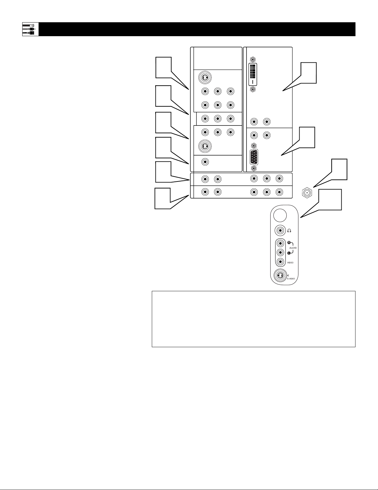
Panel Jack Compatibility Information
Jack Panel Located
on the Left Side of
the TV
SIDE JACK PANEL
Signals accepted: NTSC (480i).
Inputs available: S-Video (Y/C)
and CVBS, plus audio left and
right.
Output available: Headphone.
Only one of the inputs can be used
at a time. Select the Side source,
and the TV detects the input to
which you have connected.
Connections must be made to the
audio inputs for sound.
10
1
AV 1 Input Jacks
Signals accepted: NTSC (480i).
Inputs available: YPbPr, S-Video (Y/C), and
CVBS, plus audio left and right.
Use only one of the video signal inputs at a time.
If you should forget and have more than one type of
signal connected, the set will automatically show the
one of better quality: CVBS—good, S-Video—better, and YPbPr—best. For sound, connections must
be made to the AV1 audio inputs.
2
MON OUT Output Jacks
Provide video and audio output signals from all TV
when those sources are being viewed on the main
screen. Output from the audio L/R jacks is at a fixed
volume level; changing the TV volume does not
affect them. Adjust the volume at your external
home cinema system.
3
AV 2 Input Jacks
Signals accepted: NTSC (480i).
Inputs available: S-Video (Y/C) and CVBS, plus
audio left and right.
Use only one of the video signal inputs at a time.
If you should forget and have both types of signal
connected, the set will automatically show the
S-Video, since it is of better quality than CVBS. For
sound, connections must be made to the AV2 audio
inputs.
4
SUB OUT Output Jack
Provides a signal to an external powered subwoofer.
5
AV3 Input Jacks
Signals accepted: NTSC (480i), 480p, 720p, and
1080i, plus audio left and right.
Inputs available: YPbPr, plus audio. For sound,
connections must be made to the AV3 audio inputs.
6
AV4 Input Jacks
Signals accepted: NTSC (480i), 480p, 720p, and
1080i, plus audio left and right.
Inputs available: YPbPr, plus audio. For sound,
connections must be made to the AV4 audio inputs.
7
TUNER Input Jack
Signals accepted: RF modulated NTSC.
Inputs available: 75Ω RF coaxial.
8
AV5 Input Connectors
Signals accepted: NTSC (480i), 480p, 720p, 1080i,
and VGA plus audio left and right.
Inputs available: RGB+HV. For sound, connections must be made to the AV5 audio inputs.
9
AV6 Input Connectors
Signals accepted: Digital only (TMDS [Transition
Minimized Differential Signaling] encoded, uncom-
pressed); DVI 480i, 480p, 720p, and 1080i, plus
audio left and right.
Inputs available: DVI TMDS, plus audio. For
sound, connections must be made to the AV6 audio
inputs.
Intended use of the input: digital set-top boxes and
inputs from other digital video devices.
NOTE: This DVI jack is not for computer connections. VGA cannot be connected.
Definitions:
NTSC—National Television System Committee.
CVBS—labeled “V,” provides a small step up in quality from the Tuner (RF) input. Called
Composite Video.
S-Video (Y/C)—provides better picture quality than CVBS. Separates the signal into color and
brightness.
YPbPr—provides the best quality video signal. Called Component Video Input, the signal is
split into three parts, two color and one brightness.
C
2
SERVICE 1
1
RLV
AV1MONSUB OUT AV2AV3AV4
G
S-VIDEO
DVI
9
2
Pr Pb Y
RL
OUT
3
RL
G
S-VIDEO
4
5
5
RL
RL
6
V
V
STANDARD/
HD INPUTS
STANDARD/
HD INPUTS
AV5 AV6
RL
RL
RGB+HV
Pr Pb Y
Pr Pb Y
8
7
TUNER
10
Page 9
9
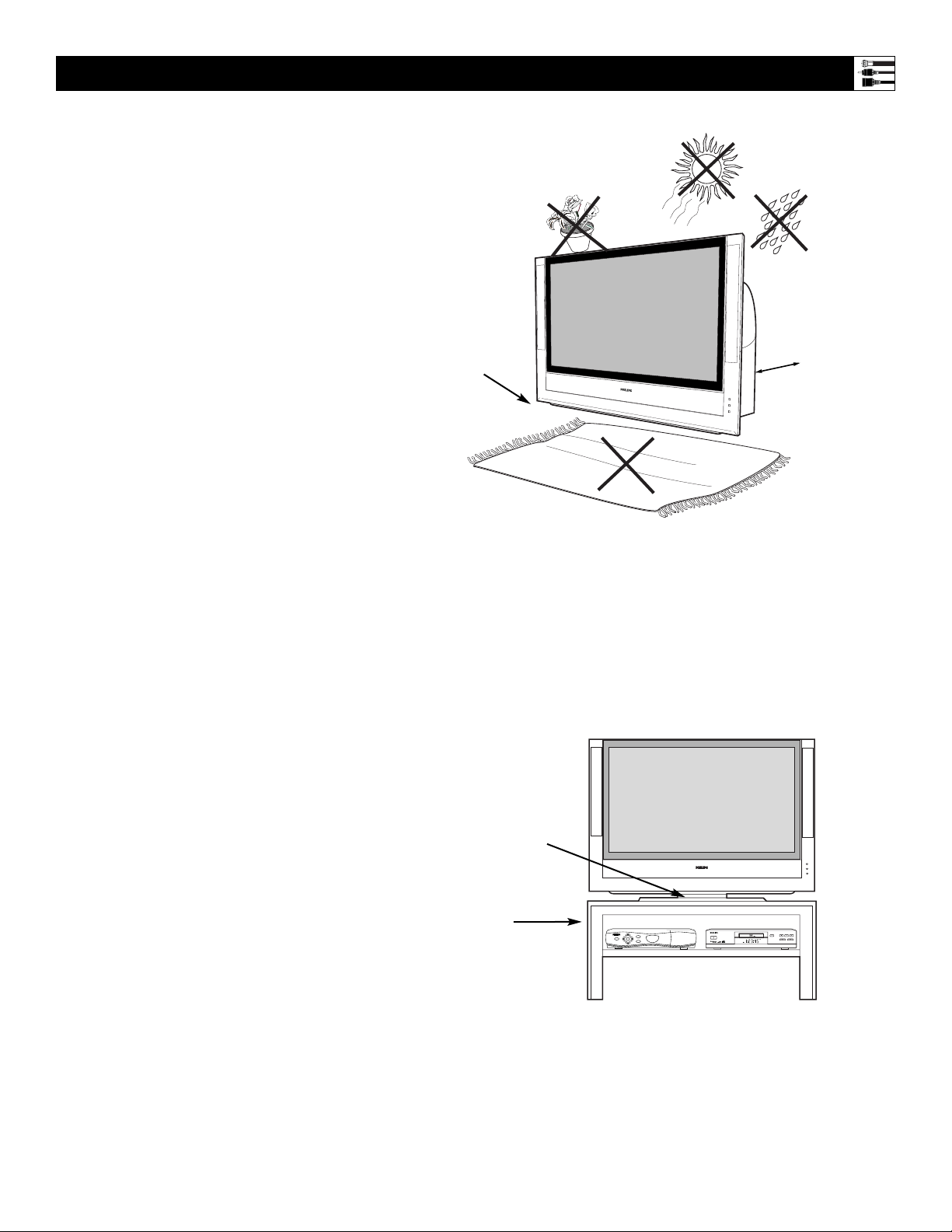
Pre-connection Recommendations
Positioning the TV
Before connecting accessory devices—VCR,
DVD player, or HD satellite receiver, for example—please keep the following in mind:
• Place the TV on a flat surface. An unlevel surface may adversely affect picture performance.
• Do not place the TV on shag carpet or any
surface that will block the ventilation openings at the bottom of the set. Blockage will
cause the TV to overheat and shut down.
• Allow 4 to 6 inches of space behind the TV
for ventilation.
• An optional swivel and an optional stand are
available for use with your TV. See your electronics dealer.
• Test various locations in the room to find the
optimal spot to locate the set for best viewing.
• Do not place the TV in direct sunlight or near
a heating appliance.
• Do not expose the TV to rain or moisture.
• To prevent any unsafe situations, do not place
objects on top of the TV.
Providing Protection Against Power
Surges
• Connect all accessory devices before you
plug any of their power cords into the wall
outlet or power strip. NEVER plug your TV
into an outlet that is controlled by a wall
switch.
• Turn off the TV and/or accessory devices
before you connect or disconnect any cables.
• Ensure that all antennas and cables are properly grounded. See page 3, “Important Safety
Instructions.”
Protecting Accessory Devices from
Overheating
• Arrange accessory devices so that air can circulate freely around them.
• Don’t stack the accessory devices. Arrange
them to allow for good ventilation. The
optional Philips stand provides enough room
for two accessory devices, side by side.
• If you connect an audio receiver or amplifier,
place it on the top shelf so the heated air from
it will not flow around other components.
Connecting Cables
Be sure to insert each cable firmly into the correct jack.
Using the Connection Examples in
This Manual
The accessory device jack panels shown are for
example purpose only. The jack panels on your
accessory devices may look different. Also, note
that connections can be made in various ways.
The examples are presented only as guides.
Allow 4 to 6 inches behind the TV
for ventilation.
Place the TV on
a flat surface.
Do not place the TV on a surface that will block
the air filters located underneath the set.
Situate the TV where
it will not be exposed
to heat or moisture.
For safety, do not
set objects on top
of the TV.
Optional Swivel
Optional Stand
DVD619 DVD/CD PLAYER
GUIDE
POWER
POWER
SELECT
INFO
HIGH DEFINITION
STANDBY-ON
STOP
OPEN/CLOSE
PLAY PAUSE
PREV NEXT
Page 10
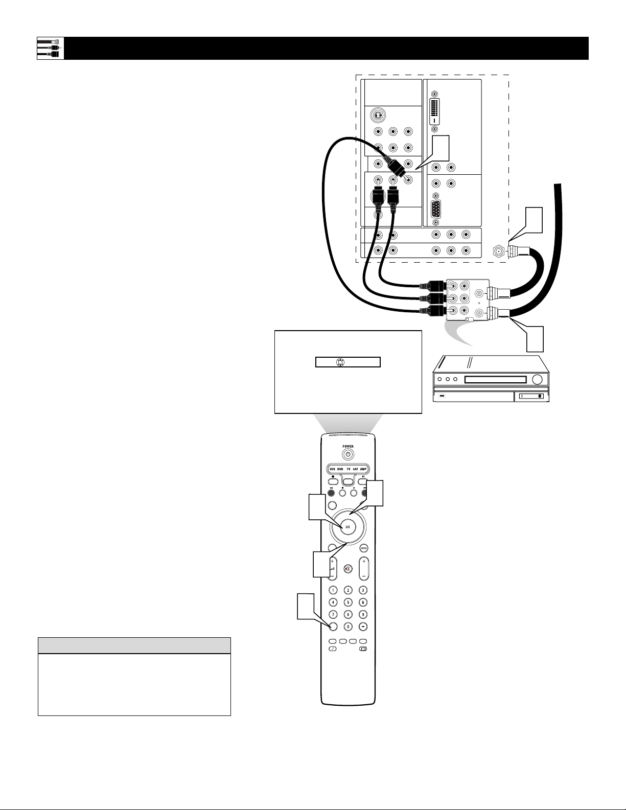
10
1
Connect the incoming antenna or cable
TV signal to the ANT IN jack on the
back of the VCR.
2
Using a coaxial cable, connect to the
OUT jack on the back of the VCR and
to the TUNER jack on the back of the
TV.
3
Using A/V cables, connect from the
AUDIO and VIDEO OUT jacks on the
back of the VCR to the corresponding
AV2 audio (L and R) and video (V)
jacks on the back of the TV.
4
Press the AV+ button on the remote
control to access the Source list.
5
Press the Cursor Up or Down button to
select the AV2 input source.
6
Press the OK button to confirm your
choice. The set is now switched to the
AV2 input source for the viewing of programs from the VCR.
NOTE: Since you’ve connected the
cable TV signal directly to the TV’s
tuner (step 2 above), you can watch the
unscrambled programs by simply tuning to the desired channel. To store
channels in the TV’s memory, you
must use Autoprogram, which you can
access through “Install” in the TV’s
on-screen menu. See the Autoprogram
section in the Quick Use and Setup
Guide that came with the TV. If you
use Autoprogram, you can select channels by pressing the CH + or – buttons
on the TV remote control (in TV
mode). Otherwise, you must press the
digit (number) buttons to tune directly
to the channel you desire.
Connecting a VCR
Back of TV
Incoming Cable TV
or Antenna Signal
Back of VCR
(example only)
Color Coding Used on Jacks and Plugs to
simplify connections:
Yellow: Video (Composite Video)
Red: Right Audio
White: Left Audio.
HELPFUL HINT
OK
Source
TV
AV1:Other
AV2:Other
AV3:Other
AV4:Other
AV5:Other
AV6:Other
SIDE
:Other
C
2
SERVICE 1
AV1MONSUB OUT AV2AV3AV4
OUT
G
S-VIDEO
RLV
Pr Pb Y
RL
V
V
RL
G
S-VIDEO
RL
STANDARD/
HD INPUTS
STANDARD/
HD INPUTS
RL
DVI
3
RL
RL
AV5 AV6
RGB+HV
Pr Pb Y
Pr Pb Y
AUDIO
L
OUT
R
VIDEO
OUT
2
TUNER
ANT
OUT
IN
IN
CH3 CH4
IN
1
4
6
5
INFO
SELECT
DNM
SURR
CC
®
®
®
ACTIVE SLEEP
CONTROL
HD
SCREEN
5
FORMAT
®
P
TIMER
CLOCK
AUTO
TV
SURF
PIP
AV+
SAP
AUTO
Page 11
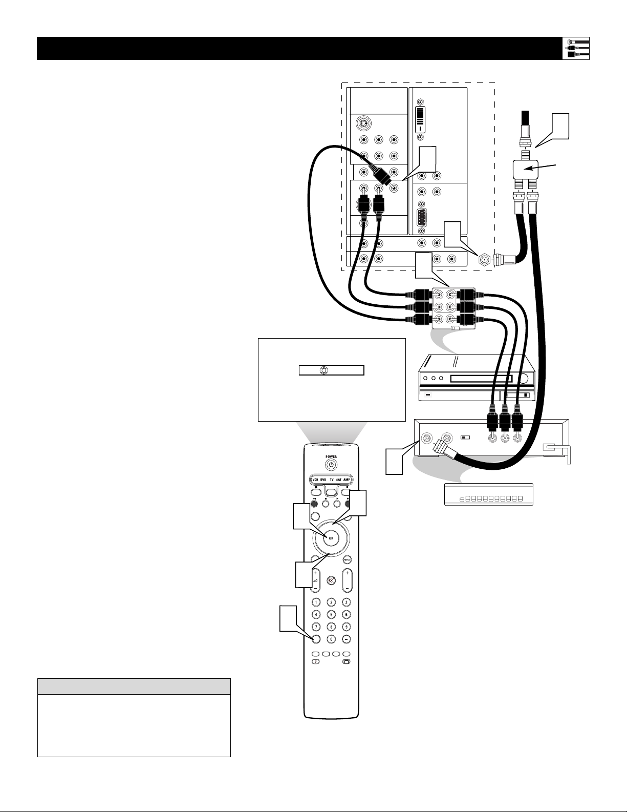
11
Connecting a VCR and Cable Box
NOTE: A cable box with AUDIO OUT jacks
such as the one used in the example on this
page might pass stereo sound to the TV. Check
with your cable TV company. The RF jack output jack on a cable box (commonly labeled
“OUT TO TV,” “OUTPUT,” or “OUT”) will
not pass stereo sound to your TV.
1
Connect the incoming cable TV signal
to a two-way signal splitter. The signal
splitter enables you to route the cable
signal to the TV without using the
OUT TO TV jack on the cable box,
which will not pass stereo sound to the
TV.
2
Using a coaxial cable, connect to one
of the connectors on the signal splitter
and to the TUNER jack on the back of
the TV.
3
Using a coaxial cable, connect to the
other connector on the signal splitter
and to the CABLE IN jack on the back
of the cable box.
4
Using Audio/Video cables, connect to
the AUDIO and VIDEO OUT jacks on
the back of the cable box and to the
corresponding AUDIO and VIDEO IN
jacks on the back of the VCR.
5
Using Audio/Video cables, connect to
the AUDIO and VIDEO OUT jacks on
the back of the VCR and to the corresponding AV2 audio (L and R) and
video (V) input jacks on the back of
the TV.
6
Press the AV+ button on the remote
control to access the Source list.
7
Press the Cursor Up or Down button to
select the AV2 input source.
8
Press the OK button to confirm your
choice. The set is now switched to the
AV2 input source for the viewing of programs from the cable box or the VCR.
Back of TV
Incoming
Cable TV
Signal
Back of VCR
(example only)
Back of Cable Box (example only)
Signal
Splitter
NOTE: Since you’ve connected the
cable TV signal directly to the TV’s
tuner (step 2 above), you can watch
the unscrambled programs by simply tuning to the desired channel. To
store channels in the TV’s memory,
you must use Autoprogram, which
you can access through “Install” in
the TV’s on-screen menu. See the
Autoprogram section in the Quick
Use and Setup Guide that came with
the TV. If you use Autoprogram,
you can select channels by pressing
the CH + or – buttons on the TV
remote control (in TV mode).
Otherwise, you must press the digit
(number) buttons to tune directly to
the channel you desire.
Color Coding Used on Jacks and Plugs to
simplify connections:
Yellow: Video (Composite Video)
Red: Right Audio
White: Left Audio.
HELPFUL HINT
Source
8
7
6
C
2
SERVICE 1
AV1MONSUB OUT AV2AV3AV4
OUT
G
S-VIDEO
RLV
Pr Pb Y
RL
V
RL
V
G
S-VIDEO
RL
STANDARD/
HD INPUTS
STANDARD/
HD INPUTS
RL
5
AV5 AV6
DVI
RL
RL
RGB+HV
Pr Pb Y
2
Pr Pb Y
1
TUNER
4
AUDIO
L
ANT
OUT
IN
OUT
R
VIDEO
IN
CH3 CH4
IN
OUT
TV
AV1:Other
OK
AV2:Other
AV3:Other
AV4:Other
AV5:Other
AV6:Other
SIDE
:Other
3
INFO
SELECT
DNM
SURR
CC
TV
SURF
PIP
AV+
SAP
AUTO
®
®
®
ACTIVE SLEEP
CONTROL
TIMER
SCREEN
FORMAT
®
P
CLOCK
AUTO
HD
7
OUTPUT
CH
CABLE
IN
3 4
TO
TV
VIDEO
OUT
RL
AUDIO
OUT
Page 12

12
1
Using an S-Video cable, connect to the
S-Video output on the back of the
S-Video device and to the AV2 SVIDEO input.
2
Using Stereo Audio cables, connect to
the AUDIO OUT jacks on the back of
the
S-Video device and to the corresponding AV2 audio inputs (L and R).
3
Press the AV+ button on the remote
control to access the Source list.
4
Press the Cursor Up or Down button to
select the AV2 input source.
5
Press the OK button to confirm your
choice. The set is now switched to the
AV2 input source for the viewing of
programs from the S-Video device.
Connecting an S-Video Device
Back of Standard S-Video Device
(example only)
Back of TV
To simplify making connections, the connectors on audio and video cables are often color
coded to match the colors on TV jacks, red for
right, and white for left.
HELPFUL HINT
2
1
TV
OK
Source
AV1:Other
AV2:Other
AV3:Other
AV4:Other
AV5:Other
AV6:Other
SIDE
:Other
C
2
SERVICE 1
AV1MONSUB OUT AV2AV3AV4
OUT
G
S-VIDEO
RLV
Pr Pb Y
RL
V
V
RL
G
S-VIDEO
RL
STANDARD/
HD INPUTS
STANDARD/
HD INPUTS
RL
DVI
RL
RL
AV5 AV6
RGB+HV
Pr Pb Y
L R
AUDIO OUT
TUNER
VIDEO
ANT/CABLE
OUT
IN
Pr Pb Y
S-VIDEO
OUT
3
5
4
INFO
SELECT
DNM
SURR
CC
TV
SURF
PIP
AV+
SAP
AUTO
®
®
®
ACTIVE SLEEP
CONTROL
TIMER
SCREEN
FORMAT
®
CLOCK
AUTO
HD
P
4
Page 13

13
1
Using Audio/Video cables, connect to
the YPbPr jacks on the back of the
standard DVD player and to the AV1
YPbPr jacks on the back of the TV.
2
Using Stereo Audio cables, connect to
the AUDIO OUT jacks on the back of
the DVD player and to the corresponding AV1 audio (L and R) jacks on the
back of the TV.
3
Press the AV+ button on the remote
control to access the Source list.
4
Press the Cursor Up or Down button to
select the AV1 input source.
5
Press the OK button to confirm your
choice. The set is now switched to the
AV1 input source for the viewing of programs from the DVD player.
Connecting a Standard DVD Player
Back of TV
Back of Standard DVD Player
(example only)
• If you do not know whether your DVD
player is standard or progressive scan, you
can connect it to either AV3 or AV4, and the
TV will automatically determine the type of
output.
• To simplify making connections, the connectors on audio and video cables are often
color coded to match the colors on TV
jacks: green for Y, blue for Pb, and red for
Pr; also red for right audio, and white for
left audio.
• The names for the component video jacks
may differ depending on the DVD player or
accessory digital source equipment used.
For example, besides YPbPr, you may see
R-Y/B-Y/Y; or CrCbY. Although abbreviations and terms may vary, the letters B and
R stand for the blue and red color component signal connectors, respectively, and Y
indicates the luminance signal. If necessary,
refer to the user manual for your DVD or
digital accessory for more information.
• If you experience difficulties receiving
sound with a DVD disc, check the sound
settings through the DVD disc’s menu.
HELPFUL HINTS
5
4
3
Source
C
2
SERVICE 1
2
AV1MONSUB OUT AV2AV3AV4
OUT
PCM-MPEG2-Dolby Digital-DTS
COAXIAL
DIGITAL AUDIO OUT
G
S-VIDEO
RLV
Pr Pb Y
RL
RL
G
S-VIDEO
RL
STANDARD/
HD INPUTS
STANDARD/
HD INPUTS
RL
SUB WF OUT
OPT OUT
DVI
1
V
RL
RL
V
AV5 AV6
RGB+HV
Pr Pb Y
(CVBS)
VIDEO OUT
TUNER
1
2
PR/C
R
Y
P
B/CB
VIDEO OUT
(Y/C)
S-VIDEO OUT
Pr Pb Y
1
2
L
R
AUDIO OUT
TV
OK
AV1:Other
AV2:Other
AV3:Other
AV4:Other
AV5:Other
AV6:Other
SIDE
:Other
INFO
SELECT
DNM
SURR
CC
TV
SURF
PIP
AV+
SAP
AUTO
®
®
®
ACTIVE SLEEP
CONTROL
TIMER
SCREEN
FORMAT
®
P
CLOCK
AUTO
HD
4
STANDBY-ON
DVD619 DVD/CD PLAYER
OPEN/CLOSE
PLAY PAUSE
STOP
PREV NEXT
Page 14

14
1
Using Audio/Video cables, connect to
the YPbPr jacks on the back of the progressive-scan DVD player and to the
AV3 or AV4 YPbPr jacks on the back of
the TV.
2
Using Stereo Audio cables, connect to
the AUDIO OUT jacks on the back of
the DVD player and to the corresponding AV3 or AV4 audio (L and R) jacks
on the back of the TV.
3
If your DVD player has an I/P switch
on the back, be sure it is set to the “P”
position for progressive-scan mode.
NOTE: Some DVD players have an
I/P switch on the back, while others
may allow the user to change the mode
by pressing a button on the DVD player’s remote control or by using the
DVD player’s on-screen menu. Also,
some DVD players have dedicated progressive-scan output jacks that are
labeled as such and require no switching by the user. See the user manual for
your DVD player for more information
on placing the player in progressivescan mode.
4
Press the AV+ button on the remote
control to access the Source list.
5
Press the Cursor Up or Down button to
select the AV3 input source.
6
Press the OK button to confirm your
choice. The set is now switched to the
AV3 input source for the viewing of programs from the DVD player.
Connecting a Progressive-scan DVD Player
Back of TV
Back of Progressive-
scan DVD Player
(example only)
• To simplify making connections, the connectors on audio and video cables are often
color coded to match the colors on TV
jacks: green for Y, blue for Pb, and red for
Pr; also red for right audio, and white for
left audio.
• The names for the component video jacks
may differ depending on the DVD player or
accessory digital source equipment used.
For example, besides YPbPr, you may see
R-Y/B-Y/Y; or CrCbY. Although abbreviations and terms may vary, the letters B and
R stand for the blue and red color component signal connectors, respectively, and Y
indicates the luminance signal. If necessary,
refer to the user manual for your DVD or
digital accessory for more information.
• If you experience difficulties receiving
sound with a DVD disc, check the sound
settings through the DVD disc’s menu.
HELPFUL HINTS
Inputs AV3–AV6 allow horizontal and vertical
picture panning using the Cursor Left, Right,
Up, and Down buttons. The Side input allows
vertical picture panning; left and right panning
with the Side input is possible when the input
has been labeled “Game.” See pages 18 and 19
for details on side panel connections and
source labeling.
HELPFUL HINT
3
Source
I
OK
SELECT
2
VIDEO OUT
P
--AV2:Other
AV3:Other
AV4:Other
AV5:Other
AV6:Other
SIDE
:Other
C
2
SERVICE 1
AV1MONSUB OUT AV2AV3AV4
Y
VIDEO
B
P
PR
G
RLV
Pr Pb Y
RL
OUT
RL
G
RL
RL
S
S-VIDEO
S-VIDEO
V
V
STANDARD/
HD INPUTS
STANDARD/
HD INPUTS
AV5 AV6
DVI
RL
RL
RGB+HV
Pr Pb Y
Pr Pb Y
AUDIO OUT
2CH
L
R
DVD619 DVD/CD PLAYER
STANDBY-ON
1
TUNER
BITSTREAM
/PCM
OPTICAL
COAXIAL
DIGITAL
AC IN ~
OPEN/CLOSE
PLAY PAUSE
STOP
PREV NEXT
4
6
5
INFO
SELECT
DNM
SURR
CC
TV
SURF
PIP
HD
SCREEN
5
FORMAT
®
®
®
®
P
AV+
ACTIVE SLEEP
CONTROL
TIMER
SAP
CLOCK
AUTO
AUTO
Page 15

15
1
Using Component Video cables, connect to the YPbPr jacks on the back of
the HD satellite receiver and to the corresponding AV3 or AV4 YPbPr jacks
on the back of the TV.
2
Using Stereo Audio cables, connect to
the AUDIO OUT jacks on the back of
the HD satellite receiver and to the corresponding AV3 or AV4 audio (L and
R) jacks on the back of the TV.
3
Refer to the user manual for the HD
satellite receiver to complete the connections to the HD satellite receiver
and to use the HD satellite receiver’s
on-screen setup menus.
4
After completing HD satellite receiver
connections and setup through the onscreen setup menus, press the AV+ button on the TV remote to access the
Source list.
5
Press the Cursor Up or Down button to
select the AV4 input source.
6
Press the OK button to confirm your
choice. The set is now switched to the
AV4 input source for the viewing of programs from the HD satellite receiver.
Connecting an HD Satellite Receiver to YPbPr
Back of TV
Back of HD
Satellite Receiver
(example only)
• To simplify making connections, the connectors on audio and video cables are often
color coded to match the colors on TV
jacks: green for Y, blue for Pb, and red for
Pr; also red for right audio, and white for
left audio.
• The names for the component video jacks
may differ depending on the DVD player or
accessory digital source equipment used.
For example, besides YPbPr, you may see
R-Y/B-Y/Y; or CrCbY. Although abbreviations and terms may vary, the letters B and
R stand for the blue and red color component signal connectors, respectively, and Y
indicates the luminance signal. If necessary,
refer to the user manual for your DVD or
digital accessory for more information.
• Inputs AV3–AV6 allow horizontal and vertical picture panning using the Cursor Left,
Right, Up, and Down buttons. The Side
input allows vertical picture panning; left
and right panning with the Side input is possible when the input has been labeled
“Game.” See pages 18 and 19 for details on
side panel connections and source labeling.
HELPFUL H
INTS
2
___
AV3:Other
OK
Source
AV4:Other
AV5:Other
AV6:Other
SIDE
:Other
C
2
SERVICE 1
V
V
CONTROL
VCR
S-VIDEO
AV5 AV6
DVI
RL
RL
RGB+HV
Pr Pb Y
Pr Pb Y
DIGITAL
AUDIO OUT
1
TUNER
OUT TO TV
CH 3
CH 4
IN FROM ANT SATELLITE IN
G
S-VIDEO
RLV
AV1MONSUB OUT AV2AV3AV4
Pr Pb Y
RL
OUT
RL
G
S-VIDEO
RL
STANDARD/
HD INPUTS
STANDARD/
HD INPUTS
RL
AUDIO
AUDIO
Y
PB
RF
PR
REMOTEPHONE JACK
L
L
RR
VIDEOVIDEO
HIGH DEFINITION
POWER
GUIDE
POWER
SELECT
INFO
4
6
5
3
User Manual
INFO
SELECT
DNM
SURR
CC
TV
SURF
PIP
AV+
SAP
AUTO
®
®
®
ACTIVE SLEEP
CONTROL
TIMER
SCREEN
FORMAT
®
CLOCK
AUTO
HD
P
5
for
HD Satellite
Receiver
Page 16

16
1
Using a DVI cable, connect to the DVI
jack on the back of the HD satellite
receiver and to the corresponding AV6
DVI jack on the back of the TV.
2
Using Stereo Audio cables, connect to
the AUDIO OUT jacks on the back of
the HD satellite receiver and to the
corresponding AV6 audio (L and R)
jacks on the back of the TV.
3
Refer to the user manual for the HD
satellite receiver to complete the connections to the HD satellite receiver
and to use the HD satellite receiver’s
on-screen setup menus.
4
After completing HD satellite receiver
connections and setup through the onscreen setup menus, press the AV+ button on the TV remote to access the
Source list.
5
Press the Cursor Up or Down button to
select the AV6 input source.
6
Press the OK button to confirm your
choice. The set is now switched to the
AV6 input source for the viewing of
programs from the HD satellite receiver.
Connecting an HD Satellite Receiver to DVI
Back of TV
Back of HD Satellite Receiver
(example only)
• To simplify making connections, the con-
nectors on audio cables are often color
coded to match the colors on TV jacks: red
for right audio, and white for left audio.
• Because DVI is such new technology, the
electronics industry is still working
toward a decision on one standard.
Philips testing has determined that compatibility issues exist with respect to a
limited number of high-definition
receivers when they are connected to the
DVI input on this television. If you
should experience difficulties, please
contact our Customer Care Center at 1800-531-0039.
• Inputs AV3–AV6 allow horizontal and verti-
cal picture panning using the Cursor Left,
Right, Up, and Down buttons. The Side
input allows vertical picture panning; left
and right panning with the Side input is
possible when the input has been labeled
“Game.” See pages 18 and 19 for details on
side panel connections and source labeling.
HELPFUL HINTS
AIR IN
SATELLITE IN
DIGITAL OUT
CABLE IN
(OPTICAL)
--AV5:Other
OK
Source
AV6:Other
SIDE:Other
DOLBY
2
RESOLUTION SELECT
1080i 720p 480p/i
C
SERVICE 1
AV1MONSUB OUT AV2AV3AV4
OUT
G
S-VIDEO
RLV
Pr Pb Y
RL
V
V
RL
G
S-VIDEO
RL
STANDARD/
HD INPUTS
STANDARD/
HD INPUTS
RL
ACCESS CARD
DVI/HDCP OUT
1
DVI
2
RL
RL
AV5 AV6
RGB+HV
Pr Pb Y
Pr Pb Y
DTV OUTPUT SELECT
RGB/Y PB P
R
DVI
RGB OUT
TV OUT
TUNER
VIDEO OUT
COMPONENT
2
1
Y
L1
P
B
L2
P
R
R1
R2
CH
AUDIO OUT
3 4
OUT
DOLBY
DIGITAL
(COAXIAL)
U
L
®
LISTED
VCR
E207602
CONTROL
7H74
AUDIO/VIDEO PRODUCT
Lt
AUDIO
TEL LINE
Rt
S-VIDEO
4
6
5
3
User Manual
INFO
SELECT
DNM
SURR
CC
TV
SURF
PIP
AV+
SAP
AUTO
®
®
®
ACTIVE SLEEP
CONTROL
HD
SCREEN
5
FORMAT
®
P
TIMER
CLOCK
AUTO
for
HD Satellite
Receiver
Page 17
17
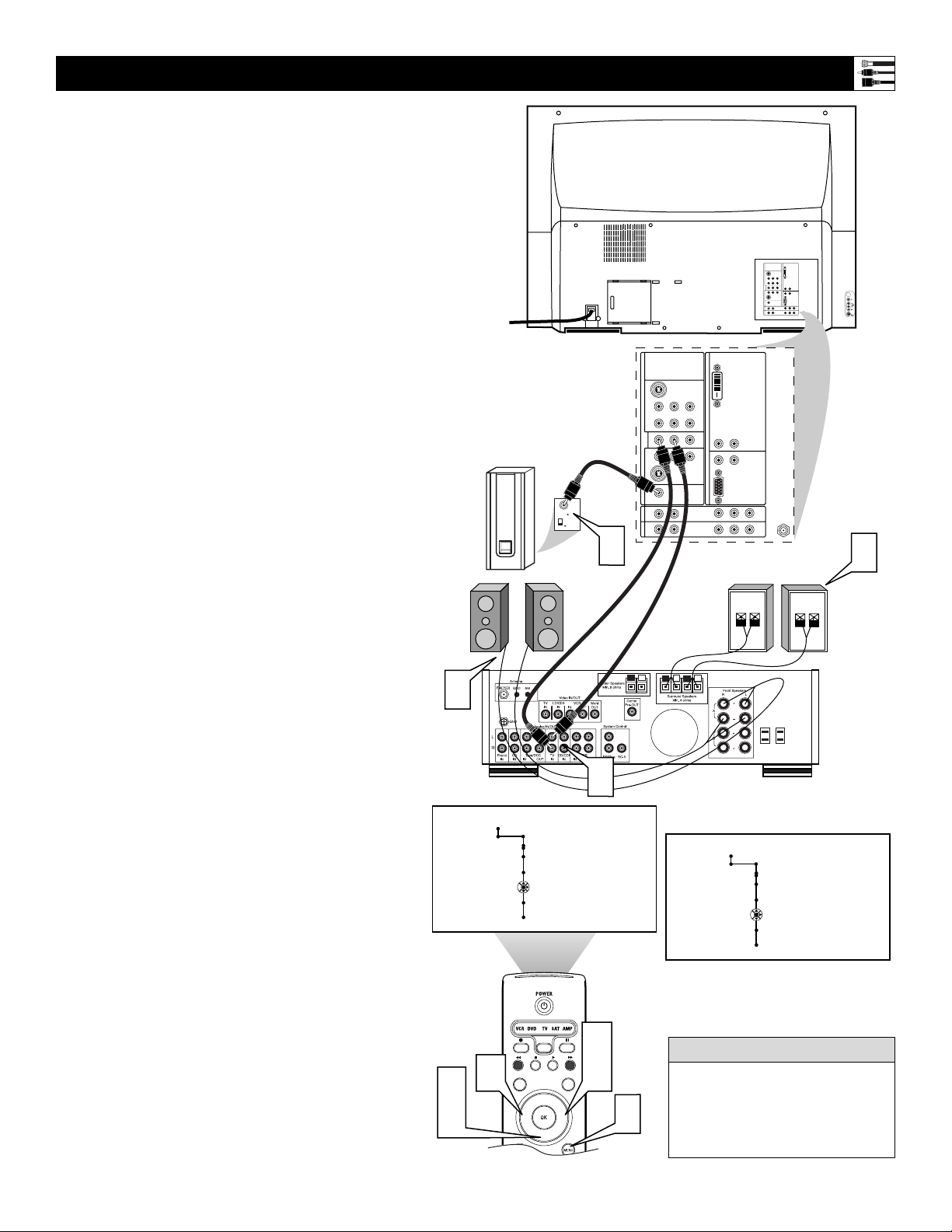
Connecting Surround Sound Equipment
Back of TV
Back of Receiver
(example only)
Surround (Back)
Speakers
Front
Speakers
Powered
Subwoofer
1
Using Stereo Audio cables, connect to
the MON OUT L and R jacks on the
back of the TV and to the corresponding TV IN jacks on the back of the
receiver.
2
Using an Audio cable, connect to the
SUB OUT jack on the back of the TV
and to the Audio Input jack on the
back of a powered subwoofer.
3
Using speaker wires, connect to the R
and L Front Speakers terminals and to
the corresponding terminals on the
backs of the front speakers.
4
Using speaker wires, connect to the
Surround Speakers terminals (+, –) on
the back of the receiver and to the corresponding terminals (+, –) on the back
of the surround speakers.
5
Press the Menu button on the remote
control to display the on-screen menu.
6
Press the Cursor Down button to select
“Settings.”
7
Press the Cursor Right button to select
“General.”
8
Press the Cursor Down button repeatedly until “Subwoofer” is selected.
9
Press the Cursor Right or Left button
to select “Yes.”
NOTE: “Yes” must be activated for the
Subwoofer menu selection before the
SUB OUT jack will supply output. This
is because the subwoofer’s low frequencies are redirected to the main TV
speakers when “No” is selected.
To simplify making connections,
the connectors on audio cables are
often color coded to match the colors on TV jacks: red for right audio,
and white for left audio.
HELPFUL HINT
3
Settings
Daylight saving
Change PIN
Subwoofer
Lamp rating
Lamp replaced
General
No • Yes
C
2
SERVICE 1
DVI
G
S-VIDEO
RLV
AV1MONSUB OUT AV2AV3AV4
Pr Pb Y
V
RL
RL
OUT
RL
RL
V
G
S-VIDEO
AV5 AV6
RGB+HV
Pr Pb Y
RL
STANDARD/
HD INPUTS
TUNER
Pr Pb Y
STANDARD/
HD INPUTS
RL
C
2
SERVICE 1
G
S-VIDEO
RLV
AV1MONSUB OUT AV2AV3AV4
Pr Pb Y
RL
OUT
RL
G
S-VIDEO
Audio
Input
180
Phase
0
RL
RL
4
STANDARD/
HD INPUTS
STANDARD/
HD INPUTS
DVI
V
V
AV5 AV6
RL
RL
RGB+HV
Pr Pb Y
Pr Pb Y
TUNER
4
+-
+
-
1
General
Settings
Daylight saving
Change PIN
Subwoofer
Lamp rating
Lamp replaced
Yes • No
6
8
9
INFO
SELECT
DNM
TV
SURF
PIP
HD
SCREEN
9
FORMAT
®
®
®
®
5
7
SURR
CC
Page 18

18
1
Using the Audio/Video cable supplied
with your video game system, connect
to the back of the game system and to
the corresponding S-VIDEO and
AUDIO (L and R) jacks in the Side
panel of the TV.
NOTE: If your game system cable
does not have an S-Video plug, you
can instead make a regular Video
connection.
2
Press the Source button on the TV
remote control to access the Source
list.
3
Press the Cursor Up or Down button to
select the Side input source.
4
Press the OK button to confirm your
choice. The set is now switched to the
Side input source for the viewing of
your video game system.
Connecting to the Side Inputs:Video Game System
Panel on
Side of
TV
Back of Game System
(example only)
The side panel is also
convenient for connecting equipment
such as camcorders or
cameras. If the equipment has an S-Video
output jack, it is the
suggested one to use
for your connection to receive the best picture. Otherwise, you can make a regular
Video connection. You must also make an
audio connection (L and R for stereo or L for
mono) to receive sound. Neither an S-Video
or Video cable carries a sound signal.
Camcorder
You can label the Side Audio/Video
input source “Game” if you would like.
See page 19 for details on labeling.
• To simplify making connections, the connectors on audio and video cables are
often color coded to match the colors on
TV jacks: yellow for video (composite),
red for right audio, and white for left
audio.
• Inputs AV3–AV6 allow horizontal and vertical picture panning using the Cursor Left,
Right, Up, and Down buttons. The Side
input allows vertical picture panning; left
and right panning with the Side input is
possible when the input has been labeled
“Game.” See page 19 for details on source
labeling.
HELPFUL HINTS
--AV6:Other
OK
Source
SIDE:Other
INFO
SELECT
DNM
SURR
CC
4
3
TV
SURF
PIP
HD
SCREEN
3
FORMAT
®
®
®
®
P
2
AV+
SAP
AUTO
ACTIVE SLEEP
CONTROL
TIMER
CLOCK
AUTO
1
Page 19

19
Labeling the Audio/Video Input Sources
This is just a sample of what the
labeling might look like. Your
Source Labels will depend on the
options you choose to label the
AV inputs.
You can label all the external Audio/Video
input sources—AV1, AV2, AV3, AV4, AV5,
AV6, and Side—according to the type of
accessory device you have connected to each
input.
After labeling, you can use the Source button
to cycle through and select your desired
source. The labels will appear alongside the
channel indicator when you select the AV
input sources.
1
Press the Menu button on the remote
control to display the on-screen menu.
2
Press the Cursor Down button to select
“Settings.”
3
Press the Cursor Right button repeatedly to select the “Source” menu.
4
Press the Cursor Down button repeatedly to select any of the AV Inputs—
AV1, AV2, AV3, AV4, AV5, AV6, or
Side. A list of labels will appear next to
the selected AV input.
5
Press the Cursor Right button to enter
the list.
6
Press the Cursor Up or Down button to
scroll and select one of the labels in the
list.
7
Press the Menu button on the remote
control to remove the on-screen menu
from the TV screen.
8
Press the Source button on the remote
control to display the list of AV inputs
and their labels.
Settings
Demo
Install
8
Picture Sound Features Channels
TV
INFO
SELECT
CC
TV
6
SURF
®
®
®
PIP
2
4
6
AV+
ACTIVE SLEEP
CONTROL
SAP
AUTO
TIMER
SURR
DNM
HD
SCREEN
FORMAT
®
P
CLOCK
AUTO
3
5
1
7
Settings
Demo
Install
Settings
Settings
Settings
TV
General Clock Source
Source
AV1
AV2
AV3
AV4
Source
AV1
AV2
AV3
AV4
Source
AV1
--Other
--Other
8
Source
OK
TV
AV1:DVD
AV2:Recorder
AV3:SAT
AV4:HD
AV5:Other
AV6:HD
SIDE:Camera
Settings
Source
---
AV1
Cable
DVD
SAT
Recorder
---
Page 20

20
Select (CBL VCR DVD SAT AMP) and Backlight
Press this button to cycle across the accessory mode dial. Stop pressing
when the mode you desire is lighted. The light will stay on for 2 seconds
and then begin blinking to indicate the remote is in your desired mode. As
long as the button blinks, the remote is in the accessory mode. (See pages
22–25 for programming the remote) Pressing and holding the Select button
for 2 seconds backlights the remote control buttons. The buttons remain
lighted for 5 seconds after you press Select.
Information Plus
Press to show information (when available) about the current channel, program, source, number or name, local time, CC availability, SAP availability, program ratings, display format, sound mode, and remaining length of a
Sleeptimer setting.
TV
Press to directly set the TV into the TV Mode of operation.
CC (Closed Captioning)
Press to turn Closed Captioning off, on, or on during mute. (See page 47
in the Directions for Use manual.)
Surf
If you set the Surf control in the TV’s on-screen menu to two channels, this
button will allow you to toggle between the current channel and the last
viewed channel. If you choose the nine-channel Surf, pressing this button
allows you to add and scroll up to nine of your favorite channels. See page
57 in the Directions for Use manual.
OK
Press to activate or confirm menu choices.
Dual Screen/PIP (Picture-in-Picture)
Press to turn the PIP dual screen on or off. Continuing to hold the Dual
Screen/PIP button down will cycle through the Dual Screen/PIP options.
(See page 58 in the Directions for Use manual.)
VOL (Volume)
Press + or – to adjust the volume.
Mute
Press to interrupt or restore sound.
Source (AV+)
Press to display a list of source options—TV, AV1, AV2, AV3, AV4, AV5,
AV6, or Side. Use the Cursor Up/Down buttons to select the next item,
then press the OK button to confirm or press the Source Select button to
select the next item in the list.
Alternate Audio (SAP)
When you tune to a channel where SAP (Second Audio Program) is available, you can toggle between Main and SAP. If SAP is not available, only
Main can be selected. (See page 42 in the Directions for Use manual.)
AutoSound™
Press to select the next item in the AutoSound™ menu. The factory-set
options are Speech, Music, Movies, and Multimedia, each corresponding
with specific settings of treble and bass. You can also select the Personal
option, which is based on the adjustments you make through the Sound
menu. (See page 46 in the Directions for Use.)
Active Control™ Plus
NOTE: Active Control™ Plus is not available for use with the AV3, AV4,
AV5, and AV6 input sources.
Press to toggle the options Off, Minimum, Medium, and Maximum.
Maximum is the recommended option. (See page 28 in the Directions for
Use manual.)
Active Control, AutoSurf, Incredible Surround, are trademarks of
Philips Consumer Electronics. Copyright 2004 Philips Consumer
Electronics. All rights reserved.
*Manufactured under license from Dolby Laboratories. “Dolby” and
the double-D symbol are trademarks of Dolby Laboratories.
Remote Control Buttons
INFO
TV
SURF
PIP
SELECT
CC
®
DNM
SURR
HD
SCREEN
FORMAT
®
®
®
P
AV+
ACTIVE SLEEP
CONTROL
SAP
AUTO
TIMER
CLOCK
AUTO
Page 21

21
Standby–On (Power)
Press to turn the TV on or off.
NOTE: The TV is never powered off completely unless it is physically
unplugged from the power source.
DNM
Press to turn the Digital Natural Motion function on or off.
VCR/DVD Mode
When in the remote control is in the VCR (DVD) mode of operation,
these buttons will allow you record, rewind, stop playback, play, or fastforward playback.
Surround Sound
Press to display a list of available sound modes. Choose from Incredible
Surround™ and Dolby* Virtual settings. (See page 41 in the Directions
for Use manual)
HD
Press to activate the AV6 (High Definition) jacks and place the TV into
the High Definition Mode of operation.
Screen Format
Press to display a list of available picture formats for showing video
images in the traditional 4:3 proportions. Press this button repeatedly to
select a picture format. Choose from Automatic, Super zoom, Panoramic,
4:3, Movie expand 14:9, Movie expand 16:9, 16:9 subtitle, and Wide
screen. See pages 35–36 in the Directions for Use manual.
NOTES:
• With AV3–AV6 connections, the Automatic picture
format option is not available.
• In Dual Screen mode, press the Picture Format button to switch
between a full or 4:3 letterbox picture format.
Cursor Up, Down, Right, Left
Use to navigate the on-screen menu and make control adjustments or settings.
Additionally, use these buttons to pan the screen up or down to show any
excluded parts of the picture.
Menu On/Off
Press to display the TV’s on-screen menu or to turn it off.
CH (Channel Selection)
Press to browse through the TV channels.
Digit (Number Buttons)
Press to directly access a specific TV channel. For a two- or three-digit
channel, enter all numbers. Press a single- digit button and hold a bit
longer to directly access a single-digit channel. These buttons can also be
used to enter values in certain on-screen menu controls.
Clock (Time Display)
Press to display the current time on the TV screen. (See page 65 in the
Directions for Use manual to set the clock)
AutoPicture™
Press to select the next item in the AutoPicture™ menu. The factory-set
options are Rich, Natural, Soft, Multimedia, and Eco, each corresponding
with specific factory settings of Contrast, Color, Sharpness, DNR,
Dynamic Contrast, and Color enhancements. You can also select the
Personal option, which is based on the adjustments or settings you make
through the Picture menu. (See page 34 in the Directions for Use.)
Sleeptimer
Press to set the sleeptimer feature to turn the TV off automatically. You
can choose—5 minutes up to 180 minutes in 5-minute increments.
INFO
Remote Control Buttons
TV
SURF
PIP
AV+
SAP
AUTO
CC
®
ACTIVE SLEEP
CONTROL
SELECT
®
®
TIMER
SURR
DNM
HD
SCREEN
FORMAT
®
P
CLOCK
AUTO
Page 22

22
Programming the Remote Control
Your TV remote control can operate accessory devices such as cable boxes, VCRs, DVD
players, satellite receivers, and amplifiers.
Normally, the remote is in TV mode. You
must press the Select button to switch the
remote to one of the accessory modes—CBL,
VCR, DVD, SAT, or AMP.
It is likely you will need to program you
remote, but, before you do, try this test:
• Press the Select button repeatedly until the
mode you desire lights up. When the light
begins blinking, point the remote toward
the accessory device, then press the
Standby–On button. If the device responds
you do not need to program the remote. If
not, follow the steps below to program the
remote.
1
Look up the number for the device on
the list below:
1 Cable (CBL)
2 VCR
3 DVD
4 Satellite (SAT)
5 Amplifier (AMP).
Look up the number for the manufacturer on pages 24–25.
2
Press the Select and Standby–On buttons at the same time, then release.
3
Press the number for the device followed by the manufacturers code. The
green Standby-On light will blink,
indicating the code is valid. If the light
does not blink, start again at step 1
using another code (if available).
CBL
VCR
DVD
SAT
AMP
STANDBY-ON
HIGH DEFINITION
POWER
GUIDE
SELECT
POWER
INFO
DVD619 DVD/CD PLAYER
OPEN/CLOSE
STOP
PREV NEXT
PLAY PAUSE
2
INFO
SELECT
DNM
SURR
CC
TV
SURF
2
®
PIP
HD
SCREEN
FORMAT
®
®
®
AV+
SAP
AUTO
ACTIVE SLEEP
CONTROL
TIMER
CLOCK
AUTO
P
3
Page 23

23
Programming the Remote Control
You can change the duration of the time-out
mode by simultaneously pressing the Select
button and a digit button, 1–4. Using digit 1
will set the time-out to 15 seconds; digit 2, 30
seconds; digit 3, 60 seconds; and digit 4, 120
seconds. The default time-out setting after
you replace the batteries in the remote is 60
seconds. All modes will have the same timeout setting.
cc
C
HECK IT OUT
If the remote control is in one of the accessory modes (a mode light is flashing)—
CBL, VCR, DVD, SAT, AMP—and you
don’t press any of the remote buttons for
sixty seconds, a “time-out” occurs, returning
the remote to TV mode.
HELPFUL HINT
Now try to use the remote control with the
accessory device to see if it is correctly programmed.
4
Press the Select button on the remote
to select the type of device. When the
mode you desire lights up, stop pressing the button. When the light begins
blinking the remote is ready for use
with the device.
5
Press the Standby–On button. As long
as the light keeps blinking, you can use
the remote with the selected device.
Once the light disappears, the remote
is back in TV mode.
If the device does not respond to the
Standby–On command, repeat steps 16 using a different code. If there are no
other for the type and brand of accessory device, the remote likely will not
operate your particular model of accessory device.
NOTE: Your TV remote is not necessarily
capable of operating all models of the brands
of accessory devices listed on pages 24–25.
You may want to try the programming
process again. Try using the number(s) that
are listed for your type and brand of device to
be sure you did not make a mistake in
inputting the digits during your first attempt
at programming.
STANDBY-ON
DVD619 DVD/CD PLAYER
4
SURF
OPEN/CLOSE
PLAY PAUSE
STOP
PREV NEXT
5
INFO
SELECT
DNM
SURR
CC
TV
®
PIP
HD
SCREEN
FORMAT
®
®
®
P
AV+
ACTIVE SLEEP
CONTROL
TIMER
SAP
AUTO
CLOCK
AUTO
Page 24

24
Programming the Remote Control: Setup Codes
Amplifier
Carver . . . . . . . . . . . . . . . . . . . . . . . . . . .0296
Curtis Mathes . . . . . . . . . . . . . . . . . . . . .0327
GE . . . . . . . . . . . . . . . . . . . . . . . . . . . . .0105
JVC . . . . . . . . . . . . . . . . . . . . . . . . . . . . .0358
Linn . . . . . . . . . . . . . . . . . . . . . . . . . . . . .0296
Magnavox . . . . . . . . . . . . . . . . . . . . . . . .0296
Marantz . . . . . . . . . . . . . . . . . . . . . . . . . .0296
Optimus . . . . . . . . . . . . . . . . . . . . .0422, 0327
Philips . . . . . . . . . . . . . . . . . . . . . . . . . . .0296
Pioneer . . . . . . . . . . . . . . . . . . . . . . . . . .0327
Polk Audio . . . . . . . . . . . . . . . . . . . . . . . .0296
RCA . . . . . . . . . . . . . . . . . . . . . . . . . . . .0327
Realistic . . . . . . . . . . . . . . . . . . . . . . . . .0422
Sony . . . . . . . . . . . . . . . . . . . . . . .0716, 0247
Soundesign . . . . . . . . . . . . . . . . . . . . . . .0105
Victor . . . . . . . . . . . . . . . . . . . . . . . . . . . .0358
Wards . . . . . . . . . . . . . . . . . . . . . . . . . . .0105
Yamaha . . . . . . . . . . . . . . . . . . . . . . . . . .0381
Cable Box
ABC . . . . . . . . . . . . . . . . . . .0030, 0034, 0035
Allegro . . . . . . . . . . . . . . . . . . . . . .0180, 0342
Americast . . . . . . . . . . . . . . . . . . . . . . . .0926
Archer . . . . . . . . . . . . . . . . . . . . . .0180, 0824
BellSouth . . . . . . . . . . . . . . . . . . . . . . . . .0926
Century . . . . . . . . . . . . . . . . . . . . . . . . . .0180
Citizen . . . . . . . . . . . . . . . . . . . . . .0180, 0342
Comtronics . . . . . . . . . . . . . . . . . . . . . . .0067
Contec . . . . . . . . . . . . . . . . . . . . . . . . . .0046
Emerson . . . . . . . . . . . . . . . . . . . . . . . . .0824
Everquest . . . . . . . . . . . . . . . . . . .0042, 0067
Focus . . . . . . . . . . . . . . . . . . . . . . . . . . .0427
Garrard . . . . . . . . . . . . . . . . . . . . . . . . . .0180
Gemini . . . . . . . . . . . . . . . . . . . . . . . . . .0042
General Instrument . . . . . . . . . . . .0503, 0837
GoldStar . . . . . . . . . . . . . . . . . . . .0067, 0171
Goodmind . . . . . . . . . . . . . . . . . . . . . . . .0824
Hamlin . . . . . . . . . . . .0047, 0036, 0286, 0061
Hytex . . . . . . . . . . . . . . . . . . . . . . . . . . . .0034
Jasco . . . . . . . . . . . . . . . . . .0042, 0180, 0342
Jerrold . . . . . . . . . . . .0030, 0039, 0503, 0042,
. . . . . . . . . . . . . . . . . . . . . . . . . . . . . . . .0837
Memorex . . . . . . . . . . . . . . . . . . . . . . . . .0027
Motorola . . . . . . . . . . . . . . . . . . . . . . . . .1133
Movie Time . . . . . . . . . . . . . . . . . . . . . . .0090
NSC . . . . . . . . . . . . . . . . . . . . . . . . . . . .0090
Oak . . . . . . . . . . . . . . . . . . . . . . . .0046, 0034
Optimus . . . . . . . . . . . . . . . . . . . . . . . . . .0048
Panasonic . . . . . . . . . . . . . .0048, 0134, 0027
Paragon . . . . . . . . . . . . . . . . . . . . . . . . .0027
Philips . . . . . . . . . . . . . . . . .0180, 0332, 0344
Pioneer . . . . . . . . . . . . . . . .0171, 0560, 0904
Popular Mechanics . . . . . . . . . . . . . . . . .0427
Pulsar . . . . . . . . . . . . . . . . . . . . . . . . . . .0027
Quasar . . . . . . . . . . . . . . . . . . . . . . . . . .0027
RCA . . . . . . . . . . . . . . . . . . . . . . . . . . . .0048
Radio Shack . . . . . . . .0042, 0910, 0342, 0824
Recoton . . . . . . . . . . . . . . . . . . . . . . . . . .0427
Regal . . . . . . . . . . . . . . . . . . . . . . .0047, 0286
Runco . . . . . . . . . . . . . . . . . . . . . . . . . . .0027
SL Marx . . . . . . . . . . . . . . . . . . . . . . . . . .0067
Samsung . . . . . . . . . . . . . . . . . . . .0067, 0171
Scientific Atlanta . . . . . . . . . .0035, 0504, 0904
Signal . . . . . . . . . . . . . . . . . . . . . .0042, 0067
Sprucer . . . . . . . . . . . . . . . . . . . . . . . . . .0048
Starcom . . . . . . . . . . . . . . . . . . . . .0030, 0042
Stargate . . . . . . . . . . . . . . . .0067, 0042, 0824
Starquest . . . . . . . . . . . . . . . . . . . . . . . . .0042
TV86 . . . . . . . . . . . . . . . . . . . . . . . . . . . .0090
Teleview . . . . . . . . . . . . . . . . . . . . . . . . .0067
Tocom . . . . . . . . . . . . . . . . . . . . . . . . . . .0039
Toshiba . . . . . . . . . . . . . . . . . . . . . . . . . .0027
Tusa . . . . . . . . . . . . . . . . . . . . . . . . . . . .0042
Unika . . . . . . . . . . . . . . . . . . . . . . . . . . . .0180
United Artists . . . . . . . . . . . . . . . . . . . . . .0034
Universal . . . . . . . . . . . . . . . . . . . .0180, 0218
Viewstar . . . . . . . . . . . . . . . . . . . . . . . . .0090
Zenith . . . . . . . . . . . . . . . . . .0027, 0552, 0926
Zentek . . . . . . . . . . . . . . . . . . . . . . . . . . .0427
Surround Sound Receiver
ADC . . . . . . . . . . . . . . . . . . . . . . . . . . . .0558
Aiwa . . . . . . . . . . . . . . . . . . . . . . . . . . . .0148
Capetronic . . . . . . . . . . . . . . . . . . . . . . . .0558
Carver . . . . . . . . . . . . . . . . .0069, 1116, 1216
Casio . . . . . . . . . . . . . . . . . . . . . . . . . . . .0222
Clarinette . . . . . . . . . . . . . . . . . . . . . . . . .0222
Denon . . . . . . . . . . . . . . . . . . . . . .1187, 1131
Fisher . . . . . . . . . . . . . . . . . . . . . . . . . . .0069
Garrard . . . . . . . . . . . . . . . . . . . . . . . . . .0490
Harman/Kardon . . . . . . . . . . . . . . . . . . . .0137
JVC . . . . . . . . . . . . . . . . . . . . . . . . . . . . .0101
Kenwood . . . . . . . . . .1054, 0069, 0213, 1340
. . . . . . . . . . . . . . . . . . . . . . . . . . .1596, 1597
Lloyd's . . . . . . . . . . . . . . . . . . . . . . . . . . .0222
MCS . . . . . . . . . . . . . . . . . . . . . . . . . . . .0066
Magnavox . . . . . . . . . .0418, 1116, 0558, 1216
. . . . . . . . . . . . . . . . . . . . . . . . . . . . . . . .0222
Marantz . . . . . . . . . . . . . . . .1116, 1216, 0066
Modulaire . . . . . . . . . . . . . . . . . . . . . . . .0222
Nakamichi . . . . . . . . . . . . . . . . . . . . . . . .0124
Onkyo . . . . . . . . . . . . . . . . . . . . . . . . . . .0162
Optimus . . . . . . . . . . .1050, 0213, 0558, 0069
Panasonic . . . . . . . . . . . . . . . . . . .0066, 1545
Penney . . . . . . . . . . . . . . . . . . . . . . . . . .0222
Philips . . . . . . . . . . . . .1116, 1216, 1296, 0418
Pioneer . . . . . . . . . . . . . . . .0177, 0558, 1050
Proscan . . . . . . . . . . . . . . . . . . . . . . . . . .1281
Quasar . . . . . . . . . . . . . . . . . . . . . . . . . .0066
RCA . . . . . . . . . . . . . . . . . . .1281, 0558, 1050
Realistic . . . . . . . . . . . . . . . . . . . . . . . . .0222
Sansui . . . . . . . . . . . . . . . . . . . . . . . . . . .1116
Sharp . . . . . . . . . . . . . . . . . . . . . . . . . . .0213
Sherwood . . . . . . . . . . . . . . . . . . . . . . . .0529
Sony . . . . . . . . . . . . . . . . . .1185, 1085, 1285
Sunfire . . . . . . . . . . . . . . . . . . . . . . . . . .1340
Teac . . . . . . . . . . . . . . . . . . . . . . . . . . . .0490
Technics . . . . . . . . . . .0066, 1335, 1545, 1336
Thorens . . . . . . . . . . . . . . . . . . . . . . . . . .1216
Victor . . . . . . . . . . . . . . . . . . . . . . . . . . . .0101
Yamaha . . . . . . . . . . . . . . . .0203, 0213, 1203
Yorx . . . . . . . . . . . . . . . . . . . . . . . . . . . . .0222
Satellite Receiver
AlphaStar . . . . . . . . . . . . . . . . . . . . . . . .0799
Echostar . . . . . . . . . . . . . . . . . . . .1032, 0802
Expressvu . . . . . . . . . . . . . . . . . . . . . . . .0802
GE . . . . . . . . . . . . . . . . . . . . . . . . . . . . .0593
General Instrument . . . . . . . .0388, 0896, 0654
HTS . . . . . . . . . . . . . . . . . . . . . . . . . . . .0802
Hitachi . . . . . . . . . . . . . . . . . . . . . . . . . . .0846
Hughes Network Systems . . . . . . . . . . . .0776
JVC . . . . . . . . . . . . . . . . . . . . . . . . . . . . .0802
Jerrold . . . . . . . . . . . . . . . . . . . . . .0388, 0654
Magnavox . . . . . . . . . . . . . . . . . . .0749, 0751
Memorex . . . . . . . . . . . . . . . . . . . . . . . . .0751
Next Level . . . . . . . . . . . . . . . . . . . . . . . .0896
Panasonic . . . . . . . . . . . . . . . . . . . . . . . .0728
Philips . . . . . . . . . . . . . . . . .1103, 0749, 0751
Primestar . . . . . . . . . . . . . . . . . . . .0654, 0388
RCA . . . . . . . . . . . . .0593, 0170, 0419, 0882
Radio Shack . . . . . . . . . . . . . . . . . . . . . .0896
Samsung . . . . . . . . . . . . . . . . . . . . . . . . .1136
Sony . . . . . . . . . . . . . . . . . . . . . . . . . . . .0666
Star Choice . . . . . . . . . . . . . . . . . . . . . . .0896
Toshiba . . . . . . . . . . . . . . . . . . . . .0776, 0817
Uniden . . . . . . . . . . . . . . . . . . . . . .0751, 0749
Zenith . . . . . . . . . . . . . . . . . . . . . . . . . . .0883
VCR
Admiral . . . . . . . . . . . . . . . . . . . . .0075, 0236
Adventura . . . . . . . . . . . . . . . . . . . . . . . .0027
Aiko . . . . . . . . . . . . . . . . . . . . . . . . . . . . .0305
Aiwa . . . . . . . . . . . . . . . . . . . . . . .0027, 0064
Akai . . . . . . . . . . . . . . . . . . . . . . . . . . . .0068
America Action . . . . . . . . . . . . . . . . . . . .0305
American High . . . . . . . . . . . . . . . . . . . .0062
Asha . . . . . . . . . . . . . . . . . . . . . . . . . . . .0267
Audiovox . . . . . . . . . . . . . . . . . . . . . . . . .0064
Beaumark . . . . . . . . . . . . . . . . . . . . . . . .0267
Bell & Howell . . . . . . . . . . . . . . . . . . . . . .0131
Broksonic . . . . .0148, 0211, 0029, 0236, 0506
CCE . . . . . . . . . . . . . . . . . . . . . . .0099, 0305
Calix . . . . . . . . . . . . . . . . . . . . . . . . . . . .0064
Canon . . . . . . . . . . . . . . . . . . . . . . . . . . .0062
Carver . . . . . . . . . . . . . . . . . . . . . . . . . .0108
Cineral . . . . . . . . . . . . . . . . . . . . . . . . . .0305
Citizen . . . . . . . . . . . . . . . . . . . . . .0305, 0064
Colt . . . . . . . . . . . . . . . . . . . . . . . . . . . . .0099
Craig . . . . . . . . .0064, 0099, 0074, 0267, 0298
Curtis Mathes . . . . . . .0062, 0068, 0087, 0189
. . . . . . . . . . . . . . . . . . . . . . . . . . . . . . . .0787
Cybernex . . . . . . . . . . . . . . . . . . . . . . . . .0267
Daewoo . . . . . . . . . . . . . . . . . . . . .0305, 0072
Denon . . . . . . . . . . . . . . . . . . . . . . . . . . .0069
Dynatech . . . . . . . . . . . . . . . . . . . . . . . . .0027
Electrohome . . . . . . . . . . . . . . . . . . . . . .0064
Electrophonic . . . . . . . . . . . . . . . . . . . . . .0064
Emerex . . . . . . . . . . . . . . . . . . . . . . . . . .0059
Emerson . . . . . . . . . .0211, 0029, 0236, 0305,
. . . . . . . . . . . . . . . . .0148, 0506, 0027, 0064,
. . . . . . . . . . . . . . . . . . . . . . . . . . . . . . . .0070
Fisher . . . . . . . . . . . . . . . . . . . . . .0074, 0131
Fuji . . . . . . . . . . . . . . . . . . . . . . . . . . . . .0062
Funai . . . . . . . . . . . . . . . . . . . . . . . . . . . .0027
GE . . . . . . . . . . . . . . .0062, 0087, 0075, 0267,
. . . . . . . . . . . . . . . . . . . . . . . . . . . . . . . .0787
Garrard . . . . . . . . . . . . . . . . . . . . . . . . . .0027
Go Video . . . . . . . . . . . . . . . . . . . .0459, 0553
GoldStar . . . . . . . . . . . . . . . . . . . .0064, 0065
Gradiente . . . . . . . . . . . . . . . . . . . . . . . .0027
HI-Q . . . . . . . . . . . . . . . . . . . . . . . . . . . .0074
Harley Davidson . . . . . . . . . . . . . . . . . . .0027
Harman/Kardon . . . . . . . . . . . . . . .0065, 0108
Harwood . . . . . . . . . . . . . . . . . . . . . . . . .0099
Hitachi . . . . . . . . . . . . . . . . .0069, 0027, 0068
Hughes Network Systems . . . . . . . . . . . .0069
JVC . . . . . . . . . . . . . . . . . . . . . . . .0094, 0068
Jensen . . . . . . . . . . . . . . . . . . . . . . . . . .0068
KEC . . . . . . . . . . . . . . . . . . . . . . . .0064, 0305
KLH . . . . . . . . . . . . . . . . . . . . . . . . . . . . .0099
Kenwood . . . . . . . . . . . . . . .0068, 0094, 0065
Kodak . . . . . . . . . . . . . . . . . . . . . .0062, 0064
LXI . . . . . . . . . . . . . . . . . . . . . . . . . . . . .0064
Lloyd's . . . . . . . . . . . . . . . . . . . . . . . . . . .0027
Logik . . . . . . . . . . . . . . . . . . . . . . . . . . . .0099
MEI . . . . . . . . . . . . . . . . . . . . . . . . . . . . .0062
MGA . . . . . . . . . . . . . . . . . . . . . . .0070, 0267
MGN Technology . . . . . . . . . . . . . . . . . . .0267
MTC . . . . . . . . . . . . . . . . . . . . . . .0027, 0267
Magnasonic . . . . . . . . . . . . . . . . . . . . . . .0305
Magnavox . . . . .0062, 0108, 0027, 0066, 0176
Page 25

25
Programming the Remote Control: Setup Codes
VCR (continued)
Magnin . . . . . . . . . . . . . . . . . . . . . . . . . .0267
Marantz . . . . . . . . . . . . . . . . . . . . .0108, 0062
Marta . . . . . . . . . . . . . . . . . . . . . . . . . . . .0064
Matsushita . . . . . . . . . . . . . . . . . . .0062, 0189
Memorex . . . . . . . . . .0131, 0074, 0506, 0027
. . . . . . . . . . . . . . . . . .0064,0075, 0062, 0267
. . . . . . . . . . . . . . . . . .0066, 0189, 0236, 1189
Minolta . . . . . . . . . . . . . . . . . . . . . . . . . .0069
Mitsubishi . . . . . . . . . . . . . . .0070, 0075, 0094
Motorola . . . . . . . . . . . . . . . . . . . .0062, 0075
Multitech . . . . . . . . . . . . . . . . . . . .0027, 0099
NEC . . . . . . . . . . . . . .0065, 0068, 0094, 0131
Nikko . . . . . . . . . . . . . . . . . . . . . . . . . . . .0064
Noblex . . . . . . . . . . . . . . . . . . . . . . . . . . .0267
Olympus . . . . . . . . . . . . . . . . . . . . . . . . .0062
Optimus . . . . . . . . . . .0189, 1189, 0075, 0064,
. . . . . . . . . . . . . . . . . . . . . . . . . . .0131, 0459
Orion . . . . . . . . . . . . .0506, 0029, 0211, 0236
Panasonic . . . . . . . . . .0062, 0189, 1189, 0643
Penney . . . . . . .0062, 0267, 0064, 0069, 0065
Pentax . . . . . . . . . . . . . . . . . . . . . . . . . . .0069
Philco . . . . . . . . . . . . . . . . . .0062, 0236, 0506
Philips . . . . . . . . . . . . . . . . .0108, 0062, 0645
Pilot . . . . . . . . . . . . . . . . . . . . . . . . . . . . .0064
Pioneer . . . . . . . . . . . . . . . . . . . . . . . . . .0094
Polk Audio . . . . . . . . . . . . . . . . . . . . . . . .0108
Profitronic . . . . . . . . . . . . . . . . . . . . . . . .0267
Proscan . . . . . . . . . . . . . . . . . . . . .0087, 0787
Protec . . . . . . . . . . . . . . . . . . . . . . . . . . .0099
Pulsar . . . . . . . . . . . . . . . . . . . . . . . . . . .0066
Quasar . . . . . . . . . . . . . . . . .0062, 0189, 1189
RCA . . . . . . . . . . . . .0087, 0176, 0069, 0062,
. . . . . . . . . . . . . . . . . . . . . .0075, 0267, 0787
Radio Shack . . . . . . . . . . . . . . . . . . . . . .0027
Radix . . . . . . . . . . . . . . . . . . . . . . . . . . . .0064
Randex . . . . . . . . . . . . . . . . . . . . . . . . . .0064
Realistic . . . . . . . . . . .0027, 0131, 0074, 0075,
. . . . . . . . . . . . . . . . . . . . . . . . . . .0064, 0062
ReplayTV . . . . . . . . . . . . . . . . . . . .0641, 0643
Runco . . . . . . . . . . . . . . . . . . . . . . . . . . .0066
STS . . . . . . . . . . . . . . . . . . . . . . . . . . . . .0069
Samsung . . . . . . . . . . . . . . . . . . . .0072, 0267
Sanky . . . . . . . . . . . . . . . . . . . . . .0066, 0075
Sansui . . .0068, 0506, 0027, 0094, 0236, 0298
Sanyo . . . . . . . . . . . . . . . . .0074, 0131, 0267
Scott . . . . . . . . . . . . . .0211, 0148, 0070, 0072
Sears . . . . . . . . . . . . .0064, 0069, 0027, 0062,
. . . . . . . . . . . . . . . . . . . . . . . . . . .0074, 0131
Semp . . . . . . . . . . . . . . . . . . . . . . . . . . .0072
Sharp . . . . . . . . . . . . . . . . . . . . . . . . . . .0075
Shintom . . . . . . . . . . . . . . . . . . . . . . . . . .0099
Shogun . . . . . . . . . . . . . . . . . . . . . . . . . .0267
Singer . . . . . . . . . . . . . . . . . . . . . . . . . . .0099
Sony . . . . . . . . . . . . . .0059, 0027, 0062, 0063
Sylvania . . . . . . . . . . .0062, 0108, 0027, 0070
Symphonic . . . . . . . . . . . . . . . . . . . . . . .0027
TMK . . . . . . . . . . . . . . . . . . . . . . . . . . . .0267
Tatung . . . . . . . . . . . . . . . . . . . . . . . . . . .0068
Teac . . . . . . . . . . . . . . . . . . . . . . .0027, 0068
Technics . . . . . . . . . . . . . . . . . . . .0062, 0189
Teknika . . . . . . . . . . . . . . . .0027, 0062, 0064
Thomas . . . . . . . . . . . . . . . . . . . . . . . . . .0027
Tivo . . . . . . . . . . . . . . . . . . . . . . . .0645, 0663
Toshiba . . . . . . . . . . . . . . . . . . . . .0072, 0070
Totevision . . . . . . . . . . . . . . . . . . .0064, 0267
Unitech . . . . . . . . . . . . . . . . . . . . . . . . . .0267
Vector . . . . . . . . . . . . . . . . . . . . . . . . . . .0072
Vector Research . . . . . . . . . . . . . . . . . . .0065
Video Concepts . . . . . . . . . . . . . . . . . . . .0072
Videosonic . . . . . . . . . . . . . . . . . . . . . . . .0267
Wards . . . . . . . . . . . .0062, 0087, 0027, 0074,
. . . . . . . . . . . . . . . . .0267, 0069, 0075, 0099
. . . . . . . . . . . . . . . . . . . . . .0108, 0176, 0787
White Westinghouse . . . . . . .0099, 0305, 0236
XR-1000 . . . . . . . . . . . . . . . .0099, 0027, 0062
Yamaha . . . . . . . . . . . . . . . . . . . . . . . . . .0065
Zenith . . . . . . . . . . . . .0066, 0027, 0236, 0506
Digital Video Disc (DVD)
Apex . . . . . . . . . . . . . . . . . . . . . . . . . . . .0699
Denon . . . . . . . . . . . . . . . . . . . . . . . . . . .0517
Fisher . . . . . . . . . . . . . . . . . . . . . . . . . . .0697
GE . . . . . . . . . . . . . . . . . . . . . . . . . . . . .0549
Hitachi . . . . . . . . . . . . . . . . . . . . . . . . . . .0691
Hiteker . . . . . . . . . . . . . . . . . . . . . . . . . .0699
JVC . . . . . . . . . . . . . . . . . . . . . . . .0650, 0585
Kenwood . . . . . . . . . . . . . . . . . . . .0709, 0561
Konka . . . . . . . . . . . . .0746, 0738, 0747, 0748
Magnavox . . . . . . . . . . . . . . . . . . .0530, 0702
Marantz . . . . . . . . . . . . . . . . . . . . . . . . . .0566
Mitsubishi . . . . . . . . . . . . . . . . . . . . . . . .0548
Onkyo . . . . . . . . . . . . . . . . . . . . . . . . . . .0530
Optimus . . . . . . . . . . . . . . . . . . . . . . . . . .0598
Oritron . . . . . . . . . . . . . . . . . . . . . . . . . . .0678
Panasonic . . . . . . . . . . . . . . . . . . .0517, 0659
Philips . . . . . . . . . . . . . . . . . . . . . .0566, 0530
Pioneer . . . . . . . . . . . . . . . .0598, 0552, 0659
Proscan . . . . . . . . . . . . . . . . . . . . . . . . . .0549
RCA . . . . . . . . . . . . . . . . . . . . . . .0549, 0598
Samsung . . . . . . . . . . . . . . . . . . . . . . . . .0600
Sharp . . . . . . . . . . . . . . . . . . . . . . . . . . .0657
Sony . . . . . . . . . . . . . . . . . . . . . . . . . . . .0560
Technics . . . . . . . . . . . . . . . . . . . . . . . . .0517
Theta Digita . . . . . . . . . . . . . . . . . . . . . . .0598
Toshiba . . . . . . . . . . . . . . . . . . . . . . . . . .0530
Yamaha . . . . . . . . . . . . . . . . . . . . .0517, 0572
Zenith . . . . . . . . . . . . . . . . . . . . . .0618, 0530
Page 26

26
Operating Accessory Devices with the TV Remote
Point the front of the remote
toward the front of the
accessory device, then press
the necessary buttons to perform the functions you
desire. Refer to pages 27 to
see the functions of the buttons in the respective accessory modes.
To backlight the
remote control buttons, press and hold
the Select button for
two seconds. If you do not press
any remote buttons for five seconds, the backlight switches off.
Each time you press a remote button while the backlight is on, the
five-second time-out function is
reset. After the backlight switches
off, you must press and hold the
Select button for two seconds to
turn it back on.
You can change the duration of the time-out
mode by simultaneously pressing the Select
button and a digit button, 1–4. Using digit 1
will set the time-out to 15 seconds; digit 2, 30
seconds; digit 3, 60 seconds; and digit 4, 120
seconds. The default time-out setting after
you replace the batteries in the remote is 60
seconds. All modes will have the same timeout setting.
cc
C
HECK IT OUT
Once you have programmed your TV remote,
refer to page 27 to see how the remote functions with accessory devices.
Before the remote will operate an accessory
device, you must select the correct mode:
CBL (cable box), VCR, DVD, SAT (satellite),
or AMP (amplifier).
1
Press the Select button to cycle through
the accessory modes. When the mode
you want lights up, stop pressing the
button. After a few seconds, the light
will begin blinking. The blinking
means that the remote is in the accessory mode you have selected.
NOTE: The remote is in accessory
mode as long as the light keeps blinking. If you do not use the remote for
60 seconds the light will switch off,
and the TV will go back to TV mode.
The 60-second timer restarts each time
you use the remote in an accessory
mode.
2
Point the front of the remote toward
the front of the accessory device, then
press the button to perform the desired
function.
●
Press the Select button once to return the
remote to the TV mode.
●
Press the Select Button twice to select
another device by cycling through the
accessory mode choices.
HELPFUL HINT
POWER
HIGH DEFINITION
SELECT
1
TV
SURF
GUIDE
INFO
INFO
PIP
AV+
SAP
AUTO
POWER
CC
®
ACTIVE SLEEP
CONTROL
SELECT
®
®
TIMER
SURR
DNM
HD
SCREEN
FORMAT
®
P
CLOCK
AUTO
2
Page 27

Operating Accessory Devices with the TV Remote
27
VCR Mode
Power On/Off
Pause
Play
Fast-Forward
Channel +, –
Digits
PIP
AutoPicture™
*Point remote at TV when using this button.
Mode Select
Display
Rewind
Stop
Record
Cursor Up,
Down, Right,
Left
OK
Menu On/Off
Volume +, –
Mute
Surround
AutoSound™
DVD Mode
Power On/Off
Pause
Play
Fast-Forward
Subtitles
Previous
Track/Next Track
Digits
Title/Chapter
PIP
AutoPicture™
*Point remote at TV when using this button.
Mode Select
Display
Stop
Rewind
Cursor Up,
Down, Right,
Left
OK
Menu On/Off
Mute
Volume +, –
Surround
AutoSound™
SAT Mode
Power On/Off
Mute
Previous Track
Digits
AutoSound™
*Point remote at TV when using this button.
Mode Slect
Display
Cursor Up,
Down, Right,
Left
OK
Menu
Volume +, –
Next Track
AutoSound™
AMP Mode
Power Off
Search Up
RDS Toggle
Channel +, –
Digits
Freq. Direct
*Point remote at TV when using this button.
Mode Select
Search Down
News
Cursor Up,
Down, Right,
Left
OK
Menu
Volume +, –
Channel Up
INFO
SELECT
DNM
SURR
CC
TV
SURF
®
PIP
AV+
SAP
AUTO
®
®
ACTIVE SLEEP
CONTROL
TIMER
SCREEN
FORMAT
®
P
CLOCK
AUTO
HD
INFO
SELECT
DNM
SURR
CC
®
®
ACTIVE SLEEP
CONTROL
TIMER
SCREEN
FORMAT
®
P
CLOCK
AUTO
HD
TV
SURF
®
PIP
AV+
SAP
AUTO
INFO
SELECT
DNM
SURR
CC
®
®
ACTIVE SLEEP
CONTROL
TIMER
SCREEN
FORMAT
®
P
CLOCK
AUTO
HD
TV
SURF
®
PIP
AV+
SAP
AUTO
INFO
SELECT
DNM
SURR
CC
®
®
ACTIVE SLEEP
CONTROL
TIMER
HD
SCREEN
FORMAT
®
P
CLOCK
AUTO
TV
SURF
®
PIP
AV+
SAP
AUTO
Page 28

28
Active Control™ Plus monitors incoming
video signals from the Tuner, AV1, AV2, and
Side inputs and adjusts key picture settings
for best picture quality. In addition to measuring picture noise, this feature uses an ambient
light sensor (located on the front of the TV)
to adjust the picture settings according to
viewing conditions in the room. When you
choose to turn Active Control™ Plus on, you
have the options Minimum, Medium, or
Maximum. Maximum is the recommended
option.
NOTE: Active Control™ Plus is disabled
with the AV3–AV6 input sources.
1
Press the Active Control™ button on
the remote control to display the
“Active Control” menu.
2
Press the Cursor Up or Down button to
select one of the options: “Minimum,”
“Medium,” “Maximum,” or “Off.”
3
Press the Cursor Right button to display the Active Control™ information
window. You will notice how the values constantly change while Active
Control™ is working.
NOTE: The Active Control™ values
shown in the information window will
based on the current AutoPicture™ setting: Personal, Rich, Natural, Soft,
Multimedia, or Eco.
4
Press the OK button to return to the
Active Control Menu or the Menu button to remove the on-screen menu from
the TV screen.
Using Active Control™ Plus
Active Control™ Plus Settings
Minimum—Sharpness, Dynamic Contrast,
and Noise Reduction are controlled automatically.
Medium—Sharpness, Color, Dynamic
Contrast, and Noise Reduction are controlled automatically.
Maximum—Sharpness, Color, Dynamic
Contrast, Noise Reduction, and Contrast are
controlled automatically.
HELPFUL HINTS
Active Control
Off
Minimum
Medium
Maximum
Active Control
Off
Minimum
Medium
Maximum
INFO+
4
1
2
2
TV
SURF
INFO
PIP
AV+
SAP
AUTO
®
SELECT
SURR
CC
®
®
ACTIVE SLEEP
CONTROL
TIMER
DNM
HD
SCREEN
FORMAT
®
P
CLOCK
AUTO
3
4
Active Control : Minimum
Auto Picture
Dynamic Contrast
Sharpness
DNR
i
Personal
10
51
4
Page 29

29
Selecting an AutoPicture™ Option
AutoPicture™ Options
Personal settings are based on your personal
choice or viewer control preferences.
Rich emphasizes very vibrant colors. (This is
a good choice when AV mode is used in a
brightly lighted room.)
Natural sets picture controls at mid-level settings for consistent viewing conditions.
Soft emphasizes warm colors. (This is a good
choice for dimly lighted room. It gives a cinema-like effect when the light is switched off.)
NOTE: This option can also be used with the
PixelPlus™ control to soften the appearance
of harsh screen elements that can show with
certain types of DVD playback conditions.
See page 30 for information about
PixelPlus™.
Multimedia emphasizes soft colors. (This is
a good choice for playing computer games,
for example.)
B&W optimizes brightness and contrast settings for viewing black and white programs.
Whether you’re watching a movie or playing
a video game, your TV has automatic video
control settings to match your current program source or content. AutoPicture™ quickly resets your TV’s video controls for a number of different types of programs and viewing conditions that you may have in your
home. The Personal AutoPicture™ settings
are the same as the Picture control adjustments made within the on-screen menu.
1
Press the Menu button on the remote to
display the on-screen menu.
2
Press the Cursor Right button to select
“Picture.”
3
Press the Cursor Down button repeatedly until the “Auto picture” control is
selected.
4
Press the Cursor Right button to enter
the AutoPicture™ submenu.
5
Press the Cursor Down or Up button to
select one of the AutoPicture™
options: “Personal,” “Rich,” “Natural,”
“Soft,” “Multimedia,” or “Eco.”
6
Press the Menu button to remove the
on-screen menu from the TV screen.
7
You can also select the AutoPicture™
settings directly by pressing the
AutoPicture™ button on the remote
control.
HELPFUL HINTS
NOTE: The Personal option shows the personal settings made in the
Picture submenu. When you select one of the preset AutoPicture™
options, those settings become the Personal settings.
Settings
Demo
Install
Picture Sound Features Channels
TV
Picture Sound Features Channels
TV
Auto Picture
Contrast
Brightness
Color
Picture
5
3
TV
SURF
TV
Auto Picture
Contrast
Brightness
INFO
SELECT
DNM
SURR
CC
®
PIP
HD
SCREEN
FORMAT
®
®
®
2
4
P
TV
Auto picture
Color
Personal
Rich
Natural
Soft
---
Picture
Personal
Rich
Natural
Soft
---
1
5
6
AV+
ACTIVE SLEEP
CONTROL
TIMER
SAP
AUTO
CLOCK
AUTO
7
TV
Auto picture
Picture
Personal
Rich
Natural
Soft
Multimedia
Eco
Page 30

30
To adjust your TV picture controls, select a channel and follow these steps.
1
Press the Menu button on the remote control to show the on-screen menu.
2
Press the Cursor Right button to select
“Picture.”
3
Press the Cursor Down button to select
one of the picture adjustments: “Contrast,”
“Brightness,” “Color,” “Sharpness,”
“Color temperature,” or “Tint.”
NOTE: The menu will show only four items at a
time, so you will need to continue scrolling with
the Cursor Down button to adjust the color temperature and tint.
4
Press the Cursor Left or Cursor Right button to adjust the selected control. Or, if
color temperature is chosen, press the
Cursor Right button to choose from the
options “Normal,” “Warm,” or “Cool.”
5
Press the Menu button to remove the onscreen menu from the TV screen.
Adjusting/Setting the Picture Controls
• The tint control is not available with the
AV3 - AV6 input sources.
Picture Control Settings
• Brightness adds or subtracts light from the
darkest part of the picture.
• Color adds or eliminates color.
• Sharpness improves the detail in the pic-
ture.
• Tint adjusts the picture to obtain natural
skin tones.
• Color temperature offers “Normal,”
“Cool,” or “Warm” picture preferences.
• Normal keeps whites, white.
• Cool makes whites, bluish.
• Warm makes whites, reddish.
HELPFUL HINTS
Settings
Demo
Install
4
Picture Sound Features Channels
TV
INFO
SELECT
CC
TV
SURF
®
®
®
PIP
3
AV+
ACTIVE SLEEP
CONTROL
SAP
AUTO
SURR
TIMER
DNM
HD
SCREEN
FORMAT
®
P
CLOCK
AUTO
2
4
1
5
TV
Contrast
Brightness
Sharpness
TV
Contrast
Brightness
Sharpness
TV
Color Temperature
Digital processing
Dynamic contrast
Color enhancement
Auto picture
Picture format
Picture Sound Features Channels
Color
Picture
40
Color
Picture
Normal
Warm
Cool
DNR
Picture
TV
Tint
40
Page 31

31
The Digital Processing control gives you a
choice of different picture scanning modes.
Progressive Scan doubles the number of picture lines, eliminating line flicker and providing a jitter-free picture.
Movie Plus provides motion compensation to
increase clarity around moving images in the
picture.
1
Press the Menu button on the remote to
display the on-screen menu
.
2
Press the Cursor Right button to select
“Picture.”
3
Press the Cursor Down button repeatedly until the “Digital processing” control is selected.
4
Press the Cursor Right button to enter
the digital processing submenu.
5
Press the Cursor Up or Down button to
select Progressive Scan, or Movie Plus.
6
Press the Menu button to remove the onscreen menu from the TV screen.
Selecting a Digital Processing Option
The Digital Processing control is not available for use with the AV3, AV4, AV5, or
AV6 input sources.
HELPFUL HINT
Settings
Demo
Install
Picture Sound Features Channels
TV
INFO
SELECT
CC
TV
5
SURF
®
®
®
PIP
3
SURR
DNM
HD
SCREEN
FORMAT
®
P
2
4
1
TV
Contrast
Brightness
Sharpness
TV
Contrast
Brightness
Sharpness
TV
Color Temperature
Digital processing
Dynamic contrast
Picture Sound Features Channels
Color
Picture
40
Color
Picture
Progressive Scan
Movie Plus
DNR
5
AV+
SAP
AUTO
ACTIVE SLEEP
CONTROL
TIMER
CLOCK
AUTO
6
TV
Digital processing
TV
Digital processing
Picture
Progressive Scan
Movie Plus
OR
Picture
Progressive Scan
Movie Plus
Page 32

32
The Dynamic Contrast control allows you to
sharpen the picture quality by making dark
portions of the picture darker and light portions of the picture more noticeable.
Normally, you will probably want to select
Medium. In certain circumstances, however,
you may prefer Minimum or Maximum.
1
Press the Menu button on the remote to
display the on-screen menu.
2
Press the Cursor Right button to select
Picture.
3
Press the Cursor Down button repeatedly until the “Dynamic contrast” control is selected.
4
Press the Cursor Right button to enter
the Dynamic Contrast submenu.
5
Press the Cursor Up or Down button to
select one of the Dynamic Contrast
options: “Off,” “Minimum,”
“Medium,” or “Maximum.”
6
Press the Menu button to remove the
on-screen menu from the TV screen.
Selecting a Dynamic Contrast Option
The Dynamic Contrast control is not available for use with input sources AV3–AV6.
HELPFUL HINT
Settings
Demo
Install
Picture Sound Features Channels
TV
INFO
SELECT
CC
TV
5
SURF
®
®
®
PIP
3
5
AV+
ACTIVE SLEEP
CONTROL
TIMER
SAP
AUTO
SURR
DNM
HD
SCREEN
FORMAT
®
P
CLOCK
AUTO
2
4
1
6
TV
Contrast
Brightness
Color
Sharpness
TV
Contrast
Brightness
Color
Sharpness
TV
Color Temperature
Digital processing
Dynamic contrast
TV
Dynamic contrast
Picture Sound Features Channels
Picture
40
Picture
Off
Minimum
DNR
Medium
Maximum
Picture
Off
Minimum
Medium
Maximum
Page 33

33
For many reasons, one of which is poor cable
reception, the picture can sometimes appear
slightly “speckled” (an indication of signal
noise in the picture). The DNR (Dynamic
Noise Reduction) control can help eliminate
this type of interference and improve the
quality of the picture.
1
Press the Menu button on the remote to
display the on-screen menu.
2
Press the Cursor Right button to select
“Picture.”
3
Press the Cursor Down button repeatedly until the DNR control is selected.
4
Press the Cursor Right button to enter
the DNR submenu.
5
Press the Cursor Up or Down button to
select one of the DNR options: Off,
Minimum, Medium, or Maximum.
6
Press the Menu button to remove the
on-screen menu from the TV screen.
Selecting a DNR (Dynamic Noise Reduction) Option
DNR is not available for use with input
sources AV3–AV6.
HELPFUL HINT
Settings
Demo
Install
Picture Sound Features Channels
TV
INFO
SELECT
CC
TV
5
SURF
®
®
®
PIP
3
5
SURR
DNM
HD
SCREEN
FORMAT
®
P
2
4
1
6
TV
Contrast
Brightness
Sharpness
TV
Contrast
Brightness
Sharpness
TV
Color temperature
Digital processing
Dynamic contrast
TV
Picture Sound Features Channels
Color
Picture
40
Color
Picture
DNR
Off
Minimum
Medium
Maximum
Picture
AV+
SAP
AUTO
ACTIVE SLEEP
CONTROL
TIMER
CLOCK
AUTO
Off
DNR
Minimum
Medium
Maximum
Picture
TV
Off
DNR
Minimum
Medium
Maximum
Page 34

34
The Color Enhancement control can improve
the picture quality of pictures with a high saturation of color. This control works in four
ways:
Dynamic Blue Stretch corrects the white colors toward a more bluish-colored white without changing the other colors. Improves the
sharpness of the picture.
Green Enhancement offers a more saturated
green color in case of low green broadcasts,
giving landscapes a fresher and brighter look.
Color-dependent Sharpness improves the
sharpness of the picture through the color
information. Gives the picture more details,
especially in red colors.
Skin-tone Correction adjusts for over saturation of red that often appears in skin tones.
1
Press the Menu button on the remote to
display the on-screen menu.
2
Press the Cursor Right button to select
“Picture.”
3
Press the Cursor Down button repeatedly until the “Color enhancement”
control is selected.
4
Press the Cursor Right button to turn
the color enhancement control on or
off.
5
Press the Menu button to remove the
on-screen menu from the TV screen.
Turning on Color Enhancement
The color enhancement control is not available for use with inputs AV3–AV6.
HELPFUL HINT
Settings
Demo
Install
Picture Sound Features Channels
TV
INFO
SELECT
CC
TV
SURF
®
®
®
PIP
3
AV+
ACTIVE SLEEP
CONTROL
SAP
AUTO
TIMER
SURR
DNM
HD
SCREEN
FORMAT
®
P
CLOCK
AUTO
2
4
1
5
TV
Contrast
Brightness
Color
Sharpness
TV
Contrast
Brightness
Sharpness
TV
Color enhancement
Auto picture
Picture format
TV
Color enhancement
Auto picture
Picture format
Picture Sound Features Channels
Picture
40
Color
Picture
On • Off
Tint
OR
Picture
Off • On
Tint
Page 35

35
Your TV’s wide screen (16:9 aspect ratio)
delivers a home-cinema experience that isn’t
possible with a conventional (4:3 aspect ratio)
set. The 16:9 format of high-definition (HD)
programs and other widescreen-format video
sources appear more lifelike, dramatic, and
theatrical. Black or gray bars are diminished
or eliminated. As the television industry
moves toward the high-definition format standard and more HD broadcasts become available, you will be able to see the broadcasts as
they were intended—in 16:9 format.
For flexibility in viewing conventional 4:3format video sources on your TV’s wide
screen, you have the options Automatic,”
“Super zoom,” “Panoramic,” “4:3,” “Movie
expand 14:9,” “Movie expand 16:9,” “16:9
subtitle,” or “Wide screen.”
NOTE: The Automatic picture format is
disabled for AV3–AV6.
Page 36 explains how to select a picture
format option.
Selecting a Picture Format Option
The term aspect ratio refers to the relationship between the width and height of a TV
screen. Historically, TV screen width has
been 33 percent greater than its height,
amounting to a 4:3 aspect ratio. The width
of your widescreen TV, however, is nearly
80 percent greater than its height, which
means its aspect ratio is 16:9. This screen
corresponds well with the tendency of the
eyes to feel more comfortable with fields of
view and action planes that are horizontally
oriented. The wide screen is also proportionally truer to the formats in which
movies are filmed and presented in theaters.
However, many widescreen DVDs will still
display black bars to preserve the true theatrical format.
HELPFUL HINT
Conventional 4:3 Screen Size
Your TV’s 16:9 Screen Size
Your TV’s Picture Format Options
Super zoom
Removes the black or gray bars
on the sides of a 4:3-format picture with minimal distortion. Part
of the top and bottom portions of
the picture are excluded from the
screen.
Panoramic
Evenly stretches the edges of the
picture to fill the TV’s wide
screen.
4:3
Displays a conventional 4:3 picture without change. Black or
gray bars will show at the left and
right sides.
Movie expand 14:9
Expands the picture to 14:9 movie
aspect ratio. Part of the top and bottom portions of the picture are
excluded from the screen. Black or
gray bars are shown at the left and
right sides.
Movie expand 16:9
Alters the image both horizontally (stretched) and vertically
(cropped) to fill the TV’s wide
screen. Part of the top and bottom
portions of the picture will be
excluded from the screen.
16:9 subtitle
Zooms the picture for a full view
of subtitles or other information
displayed at the bottom of the
picture. Part of the top portion of
the picture is excluded from the
screen.
Wide screen
Evenly stretches the width of the
picture to fill the screen.
Automatic (not depicted)
Makes the picture fill the screen
as much as possible when the
presence of black or gray bars is
detected.
Inputs AV3–AV4 allow horizontal and vertical
picture panning using the Cursor Left, Right,
Up, and Down buttons. The Side input allows
vertical picture panning; left and right panning
with the Side input is possible when the input
has been labeled “Game.” See pages 18 and 19
for details on side panel connections and
source labeling.
cc
C
HECK IT OUT
Page 36

36
Choose a picture format size to match the
type of program you’re watching. Select the
normal 4:3 aspect ratio or a variety of
widescreen formats.
1
Press the Menu button on the remote to
display the on-screen menu.
2
Press the Cursor Right button to select
“Picture.”
3
Press the Cursor Down button repeatedly until the “Picture format” control
is selected.
4
Press the Cursor Right button to enter
the picture-format submenu.
5
Press the Cursor Down button to select
one of the seven screen formats:
“Automatic,” “Super zoom,”
“Panoramic,” “4:3,” “Movie expand
14:9,” “Movie expand 16:9,” “16:9
subtitle,” or “Wide screen.”
The Automatic option senses the presence of black or gray bars around the
picture and zooms the picture to reduce
or eliminate the bars.
NOTE: The Automatic picture format
option is not available with AV5 (computer) connections.
6
Press the Menu button to remove the
on-screen menu from the TV screen.
7
You can also select a picture format
simply by pressing the Screen Format
button on the remote control.
Selecting a Picture Format Option
Settings
Demo
Install
Picture Sound Features Channels
TV
Picture Sound Features Channels
TV
Contrast
Brightness
Color
Sharpness
7
3
5
TV
SURF
INFO
PIP
AV+
SAP
AUTO
®
SELECT
SURR
CC
®
®
ACTIVE SLEEP
CONTROL
TIMER
DNM
HD
SCREEN
FORMAT
®
P
CLOCK
AUTO
2
4
1
6
TV
Contrast
Brightness
Color
Sharpness
TV
Color enhancement
Auto picture
Picture format
TV
Picture format
TV
Picture
40
Picture
Tint
Automatic
Super zoom
Panoramic
---
Picture
Automatic
Super zoom
Panoramic
---
Picture
Picture format
Automatic
Super zoom
Panoramic
4:3
---
Page 37

37
Besides the normal volume level control, your
TV also has a headphone volume control.
This control can be adjusted when using
headphones without having to adjust the main
volume control for the TV cabinet speakers.
To control the television volume:
1
Press the Volume + button on the
remote control to increase the television volume level.
2
Press the Volume – button on the
remote control to decrease the television volume level.
NOTES:
• The Volume scroll will not appear on
screen if the on-screen display is set to
“Minimum.” See page 62 for details.
• The Volume level can also be adjusted
within the on-screen menu. Select the
Sound menu and cursor down to the
Volume control. Use the Cursor Left and
Right buttons to adjust.
To control the Headphone volume:
3
Press the Menu button on the remote
control to display the on-screen menu.
4
Press the Cursor Right button to select
“Sound.”
5
Press the Cursor Down button repeatedly until the “Headphone volume”
control is selected.
6
Press the Cursor Right button to
increase the headphone volume level.
7
Press the Cursor Left button to
decrease the headphone volume level.
8
Press the Menu button on the remote
control to remove the on-screen menu
from the TV screen.
Adjusting the TV and Headphone Volume
Television Volume
Headphone Volume
Plug your headphones into the headphone 3.5mm mini-jack in the TV’s Side
panel.
7
1
40
INFO
SELECT
CC
CC
SELECT
®
®
®
®
SURR
SURR
DNM
DNM
HD
HD
SCREEN
SCREEN
FORMAT
FORMAT
®
®
P
P
5
TV
SURF
SURF
INFO
TV
®
®
PIP
PIP
4
6
3
8
Picture Sound Features Channels
TV
Settings
Demo
Install
Sound Features Channels
TV
Volume
Equalizer
Balance
Loudness
Headphone volume
Sound
TV
Volume
Equalizer
Balance
Loudness
Headphone volume
40
2
AV+
AV+
SAP
SAP
AUTO
AUTO
ACTIVE SLEEP
ACTIVE SLEEP
CONTROL
TIMER
CONTROL
TIMER
CLOCK
CLOCK
AUTO
AUTO
Page 38

38
AutoSound™ allows you to select from four
factory-set controls and a personal control.
The personal control consists of settings you
adjust through the on-screen Sound menu.
The four factory-set controls—Speech,
Music, Movie, or Multimedia—enable you to
tailor the TV sound to enhance the particular
program you are watching. Follow these steps
to select any of the options.
1
Press the Menu button on the remote
to display the on-screen menu.
2
Press the Cursor Right button repeatedly to select “Sound.”
3
Press the Cursor Down button repeatedly until the “Auto sound” control is
selected.
4
Press the Cursor Right button to enter
the AutoSound™ submenu.
5
Press the Cursor Up or Down button to
select an option: “Speech,” “Music,”
“Movies,” “Multimedia,” or
“Personal.”
6
Press the Menu button to remove the
on-screen menu from the TV screen.
7
You can also select the AutoSound™
settings directly by pressing the
AutoSound™ button on the remote
control.
Selecting an AutoSound™ Option
AutoSound™ Options
Speech brings voices to the forefront and
emphasizes them. Moves music to the background.
Music emphasizes music over voices.
Movies provides a balance between voices
and music.
Multimedia provides sound balance best
suited for gaming consoles or interactive
media.
Personal presents the TV’s sound according
to the settings you make within the sound
menu.
HELPFUL HINTS
NOTE: The Personal option shows the personal settings made in the
Sound submenu. When you select one of the preset AutoSound™ options,
those settings become the Personal settings.
Settings
Demo
Install
Picture Sound Features Channels
TV
INFO
SELECT
CC
TV
5
SURF
®
®
®
PIP
3
5
SURR
DNM
HD
SCREEN
FORMAT
®
P
2
4
1
6
Sound Features Channels
TV
Volume
Equalizer
Balance
Loudness
Headphone volume
TV
TV
Picture
AVL
Delta volume
Auto sound
Picture
Auto sound
Personal
Speech
Music
Movies
Multimedia
Personal
Speech
Music
Movies
Multimedia
AV+
ACTIVE SLEEP
CONTROL
TIMER
SAP
AUTO
CLOCK
AUTO
7
Page 39

39
The Equalizer control will change the dynamics of the sound being heard through the TV.
You can adjust the settings for the Personal
Equalizer option. The other options have been
preset at the factory and cannot be changed.
1
Press the Menu button on the remote to
display the on-screen menu.
2
Press the Cursor Right button repeatedly to select “Sound.”
3
Press the Cursor Down button repeatedly until the “Equalizer” control is
selected.
4
Press the Cursor Right button to enter
the equalizer submenu. Continue to
press the Cursor Right button to select
one of the options: “Speech,” “Music,”
“Movie,” “Multimedia,” or “Personal.”
5
If you select the Personal option and
want to make adjustments, press the
Cursor Down button to select an
adjustment, then press the Cursor Left
or Right button to adjust the slider control to the desired position.
NOTE: If you attempt to change the settings
for the factory preset options Speech, Music,
Movie, or Multimedia, the Equalizer control
will default to the Personal option.
6
Press the Menu button to remove the
on-screen menu from the TV screen.
Selecting a TV Equalizer Option
Settings
Demo
Install
5
Picture Sound Features Channels
TV
INFO
SELECT
CC
TV
SURF
®
®
®
PIP
3
5
AV+
ACTIVE SLEEP
CONTROL
SAP
AUTO
Sound Features Channels
TV
Volume
Equalizer
Balance
Loudness
Headphone volume
Sound
TV
Auto Sound: Speech
120 Hz
500 Hz
1.5 kHz
5 kHz
10 kHz
Auto Sound: Music
120 Hz
500 Hz
1.5 kHz
5 kHz
10 kHz
SURR
DNM
HD
SCREEN
FORMAT
®
P
2
4
5
TV
Equalizer
Sound
Equalizer
1
6
TIMER
CLOCK
AUTO
TV
Sound
Equalizer
Auto Sound: Movie
120 Hz
500 Hz
1.5 kHz
5 kHz
10 kHz
TV
TV
Sound
Equalizer
Sound
Equalizer
Auto Sound: Multimedia
120 Hz
500 Hz
1.5 kHz
5 kHz
10 kHz
Auto Sound: Personal
120 Hz
500 Hz
1.5 kHz
5 kHz
10 kHz
Page 40

40
You can adjust the balance of the TV speaker
sound.
1
Press the Menu button on the remote to
display the on-screen menu.
2
Press the Cursor Right button repeatedly to select “Sound.”
3
Press the Cursor Down button repeatedly until the “Balance” control is
selected.
4
Press the Cursor Right or Left button
to adjust speaker balance.
5
Press the Menu button to remove the
on-screen menu from the TV screen.
Adjusting TV Speaker Balance
Settings
Demo
Install
4
Picture Sound Features Channels
TV
INFO
SELECT
CC
TV
SURF
®
®
®
PIP
SURR
DNM
HD
SCREEN
FORMAT
®
2
4
Sound Features Channels
TV
Volume
Equalizer
Balance
Loudness
Headphone volume
SoundAV1
TV
Volume
Equalizer
Balance
Loudness
Headphone volume
SoundAV1
TV
Volume
Equalizer
Balance
Loudness
Headphone volume
2
0
3
AV+
SAP
AUTO
ACTIVE SLEEP
CONTROL
TIMER
CLOCK
AUTO
P
1
5
Page 41
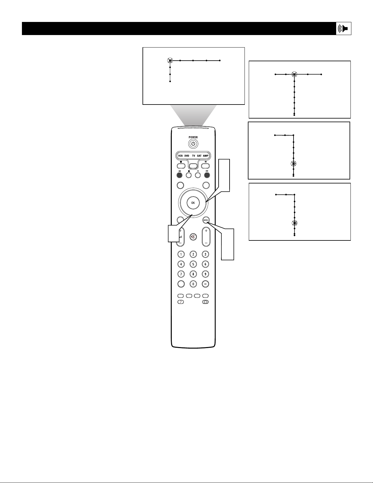
41
Turning the Loudness control on provides a
volume-dependent bass-boost effect to the
speakers. Follow the steps here to turn the
Loudness control on.
1
Press the Menu button on the remote to
display the on-screen menu.
2
Press the Cursor Right button repeatedly to select “Sound.”
3
Press the Cursor Down button repeatedly until the “Loudness” control is
selected.
4
Press the Cursor Right to toggle loudness on or off.
5
Press the Menu button to remove the
on-screen menu from the TV screen.
Turning Loudness on or off
Settings
Demo
Install
Picture Sound Features Channels
TV
Sound Features Channels
TV
Auto sound
Equalizer
Volume
Balance
Loudness
Headphone volume
3
TV
SURF
INFO
PIP
AV+
SAP
AUTO
®
SELECT
CC
®
®
ACTIVE SLEEP
CONTROL
TIMER
SURR
DNM
HD
SCREEN
FORMAT
®
P
CLOCK
AUTO
2
4
1
5
Sound
TV
Auto sound
Equalizer
Volume
Balance
Loudness
Headphone volume
Sound
TV
Auto sound
Equalizer
Balance
Loudness
Headphone volume
Off • On
Volume
On • Off
Page 42

42
Selecting a Sound Mode Option
The Sound Mode control allows you to place
the TV sound into either Incredible
Surround™ or Dolby* Virtual mode. The
steps below explain how to select one of
those options.
1
Press the Menu button on the remote to
display the on-screen menu.
2
Press the Cursor Right button repeatedly to select “Sound.”
3
Press the Cursor Down button repeatedly until the “Sound mode” control is
selected.
4
Press the Cursor Right button to enter
the sound mode submenu.
5
Press the Cursor Up or Down button to
select one of modes, either “Incr.
Surround” or “Dolby Virtual.”
Incr. Surround enhances stereo programs by making the sound broader
and fuller.
Dolby Virtual creates a virtualized
surround-sound experience from two
speakers. Dolby Virtual retains all the
original multichannel audio information and provides the listener with the
sensation of being surrounded by additional speakers.
6
When finished, press the Menu button
to remove the on-screen menu from the
TV screen.
7
You can also select a sound mode
option simply by pressing the
Surround Sound button on the remote
control.
*Manufactured under license from Dolby
Laboratories. “Dolby” and the double-D symbol are
trademarks of Dolby Laboratories.
Incredible Surround is a trademark of Philips
Consumer Electronics. Copyright 2004 Philips
Consumer Electronics. All rights reserved.
Settings
Demo
Install
Picture Sound Features Channels
TV
INFO
SELECT
CC
TV
5
SURF
®
®
®
PIP
3
5
AV+
ACTIVE SLEEP
CONTROL
SAP
AUTO
TIMER
SURR
DNM
HD
SCREEN
FORMAT
®
P
CLOCK
AUTO
7
2
4
1
6
Sound Features Channels
TV
Volume
Equalizer
Balance
Loudness
Headphone volume
Sound
TV
Sound mode
Alt Audio
Mono/Stereo
Sound
TV
Sound mode
Sound
TV
Sound mode
Sound
TV
Sound mode
Off
Incr. Surround
Dolby Virtual
Off
Incr. Surround
Dolby Virtual
Off
Incr. Surround
Dolby Virtual
Off
Incr. Surround
Dolby Virtual
Page 43

43
For broadcasts that contain SAP (Secondary
Audio Program) information, the Alt Audio
Control can be set to SAP. Sent as a third
audio channel, SAP is an additional part of the
stereo broadcast system that can be heard apart
from the current TV program sound. TV stations are free to use SAP for any number of
purposes.
If an SAP signal is not present with a selected
program, the “Alt Audio” option in the TV’s
on-screen menu cannot be selected and will
appear grayed out.
If SAP is available on the tuned channel:
1
Press the Menu button on the remote to
display the on-screen menu.
2
Press the Cursor Right button repeatedly to select “Sound.”
3
Press the Cursor Down button repeatedly until the Alt Audio control is
selected.
4
Press the Cursor Right button to toggle
and select either “Main” or “SAP.”
5
Press the Menu button to remove the
on-screen menu from the TV screen.
6
You can also select SAP by simply
pressing the Alternate Audio button on
the remote control.
Using Alternate Audio (SAP)
Settings
Demo
Install
Picture Sound Features Channels
TV
Sound Features Channels
TV
Volume
Equalizer
Balance
Loudness
Headphone volume
Sound
TV
6
3
TV
SURF
INFO
PIP
AV+
SAP
AUTO
®
SELECT
CC
®
®
ACTIVE SLEEP
CONTROL
TIMER
SURR
DNM
HD
SCREEN
FORMAT
®
P
CLOCK
AUTO
2
4
1
5
Sound mode
Mono/Stereo
TV
Sound mode
Mono/Stereo
Alt audio
Sound
Alt audio
Main • SAP
OR
SAP • Main
Page 44

44
 Loading...