

Page 1

Chassis name
Platform
Model name
TPS17.3A LA
MSD91H
50PUN6102/61
55PUN6102/61
TPS17.3A
Published by Amy.ma 1752 Quality Subject to modification 3122 785 20550
2017 © TP Vision Netherlands B.V.
All rights reserved. Specifications are subject to change without notice. Trademarks are the
property of Koninklijke Philips Electronics N.V. or their respective owners.
TP Vision Netherlands B.V. reserves the right to change products at any time without being obliged to adjust
earlier supplies accordingly.
PHILIPS and the PHILIPS’ Shield Emblem are used under license from Koninklijke Philips Electronics N.V.
2017-Dec-27
Page 2

1.Product information……….……………………………………………………………………………………3
2.Connections overview……..…..…..………………..…………………………………………………………4
3.Mechanical Instructions………………….…………………………………………………………………….5
Cable dressing (50" 6102 series)………………………………………………………………………………5
Cable dressing (55" 6102 series)………………………………………………………………………………5
Assembly/Panel Removal ………………………………………………………………………………………6
4.Service Modes…………….……………….………………….…………………………………………….….10
5.Software upgrading, Error Code and Panel Code………...……………………………………………..12
6.Circuit Descriptions…..……………………….………………………………………………………………13
7.IC Data Sheet……...……………………………………………………………………………………….…..34
8.Circuit Diagrams……………...……………………………………………………………………………….39
8.1 A 715G7374 PSU…………………………………………………………………..……………………39
8.2 A 715G9324 PSU…………………………………………………………………..……………………43
8.3 B 715G9070 SSB………………………………………………………………………………………..55
8.4 J 715G8623 IR/LED Panel…………………………………………..…………………………………101
8.5 E 715G7088 Keyboard control panel………………………………………………………………102
9.Styling Sheet……………….…………………….………………………………………………………….112
6102 series 50"………………………………………………………………………………………………112
6102 series 55"………………………………………………………………………………………………113
Published by Amy.ma 1752 Quality Subject to modification 3122 785 20550
2017 © TP Vision Netherlands B.V.
All rights reserved. Specifications are subject to change without notice. Trademarks are the
property of Koninklijke Philips Electronics N.V. or their respective owners.
TP Vision Netherlands B.V. reserves the right to change products at any time without being obliged to adjust
earlier supplies accordingly.
PHILIPS and the PHILIPS’ Shield Emblem are used under license from Koninklijke Philips Electronics N.V.
2017-Dec-27
Page 3

1. Product information
Product information may be subject to change without
prior notice. For detailed product information, please go to
www.philips.com/support
Display & Sound
Intrinsic resolution
• 3840 x 2160
Sound power
• 8W x 2
Connectivity
TV Side
• USB
• HDMI 2
• HDMI 3
TV Bottom
• Audio out (L/R)
• Optical
• Antenna
• Y/AV, Pb, Pr, Audio L/R
• HDMI(ARC)
Display resolutions
Video formats
Resolution — Refresh rate:
• 480i - 60 Hz
• 480p - 60 Hz
•• 720p - 60 Hz
• 1080i - 60 Hz
• 1080p - 24 Hz, 30 Hz, 60 Hz
• 2160p - 24 Hz, 30 Hz, 60 Hz
Computer formats
Resolution — Refresh rate:
• 720 x 400 - 70 Hz
• 640 x 480 - 60 Hz
• 800 x 600 - 60 Hz
• 1024 x 768 - 60 Hz
• 1280 x 720 - 60 Hz
• 1280 x 768 - 60 Hz
• 1280 x 1024 - 60 Hz
• 1440 x 900 - 60 Hz
• 1680 x 1050 - 60 Hz
• 1920 x 1080 - 60 Hz
Note: When the TV set does not support resolution and
refresh rate, there will be a black screen or flower screen.
Please switch to the TV set to display resolution and
refresh rate.
Multimedia
Supported storage device: USB (Supports FAT 32/FAT 16
USB storage devices.)
Playback formats
Video Codecs: MPEG1/2, MPEG4, H.264, HEVC,
Motion MPEG
Audio Codecs: MPEG1/2 layer1, MPEG1/2 layer2,
MPEG1/2 layer3, AC3, AAC
Image Codecs: png, jpeg, bmp
Power supply/ tuner/ reception/
transmission
Power supply
• Mains: 220V~, 60Hz
• Standby power consumption: ≤0.5W
• Ambient temperature : 5°C to 45°C
• Power consumption:
– 50PUN61x2: 130W
– 55PUN61x2: 160W
Tuner/ reception/ transmission
Aerial input: 75ohm coaxial (IEC75)
TV system: ATSC
Video Playback: NTSC
Tuner bands: UHF, VHF
Page 4

2. Connections Overview
YPBPR
HDMI
SCALER
USB
HDMI
Antenna
Optical
Audio out (L/R)
(For 715G9070M)
Page 5

3. Mechanical Instructions
LOUDSPEAKER
(1184)
ECN701
ECN102
ECN105 TO IR & Connector(to KEY)
KEY BOARD
CONTROL
E
CN102
CN8603
MAIN POWER
SUPPLY
(1054)
A
SSB
(1053)
B
CN701
CN602
CN105
CN9101
ECN8603
Connector
ECN01
IR/LED
BOARD
(1056)
J
LOUDSPEAKER
(1184)
ECN602
ECN602
MAIN POWER
SUPPLY
(1054)
A
CN701
CN9103
CN8601
CN102
CN105
CN602
SSB
(1053)
B
LOUDSPEAKER
(1184)
LOUDSPEAKER
(1184)
IR/LED
BOARD
(1056)
J
KEY BOARD
CONTROL
E
Connector
ECN01
ECN105
ECN105
ECN602
ECN602
ECN701
ECN102
3.1 Cable Dressing
Cable dressing (50" 6102 series)
Cable dressing (55" 6102 series)
Page 6

3.2
1 1 1
1
2
3.2.1 Stand removal
1. Remove the fixation screws [1] that secure the stand
2. Take the stand bracket out from the set.
3.2.2 IR board Control Unit
1. Unplug the connector from the SSB.
Caution: be careful, as these are very fragile connectors!
2. Remove all the fixation screws [1] and connector [2] from the IR board control unit.
When defective, replace the whole unit.
3.2.3 Rear Cover
Warning: Disconnect the mains power cord before removing the rear cover.
1. Remove fixation screws [2] and [3] that secure the back cover.
2. Unplug connector [2] carefully as key board is catch on back cover.
3. Gently lift the rear cover from the TV. Make sure that wires and cables are not damaged while lifting the rear cover from the set.
Page 7

2 2 2
2
2 2 2 2 3 3 2 2 2 2 2
2
2
2
2
2 2 2
2 3 3 3 2
3.2.3 Keyboard Control Unit
1. Release the connector from the SSB Board.
Caution: be careful, the Keyboard is catch on the Back cover, please be careful to avoid damage the fragile connectors!
2. Remove all the fixation screws[1] and connector [2] from the keyboard control panel and take it out from the Back cover
When defective, replace the whole unit.
Page 8

1
1
3 2 3
1 2 3
3
3.2.4 Small Signal Board (SSB)
Caution: it is mandatory to remount all different screws at their original position during re-assembly. Failure to do so may result in damaging the
SSB.
1. Release the clips from the LVDS connector that connect with the SSB[1].
Caution: be careful, as these are very fragile connectors!
2. Unplug all other connectors [2] .
3. Remove all the fixation screws from the SSB [3].
4. The SSB can now be shifted from side connector cover, then lifted and taken out of the I/O bracket.
Page 9

3.2.5 Power Supply Unit (PSU)
Caution: it is mandatory to remount all different screws at their original position during re-assembly. Failure to do so may result in damaging the
PSU.
1. Gently unplug all connectors from the PSU.
2. Remove all fixation screws from the PSU.
3. The PSU can be taken out of the set now.
3.2.7 Speakers
1. Gently release the tapes that secure the speaker cables.
2. Unplug the speaker connector from the SSB.
3. Take the speakers out.
When defective, replace the both units.
3.2.8 LCD Panel
1. Remove the SSB as described earlier.
2. Remove the PSU as described earlier.
3. Remove the keyboard control panel as described earlier.
4. Remove the stand bracket as described earlier.
5. Remove the IR/LED as described earlier.
6. Remove the fixations screws that fix the metal clamps to the front bezel. Take out those clamps.
7. Remove all other metal parts not belonging to the panel.
8. Lift the LCD Panel from the bezel.
When defective, replace the whole unit.
Page 10

4. Service Modes
4.1 Service Modes
The Service Mode feature is split into following parts:
Factory Mode.
Customer Service Mode (CSM).
Factory mode offer features, which can be used by the Service engineer to repair/align a TV set. Some features are:
Make alignments (e.g. White Tone).
Display information.
The CSM is a Service Mode that can be enabled by the consumer. The CSM displays diagnosis information, which the customer can forward to the
dealer or call centre. The information provided in CSM and the purpose of CSM is to:
Increase the home repair hit rate.
Decrease the number of nuisance calls.
Solved customers’ problem without home visit.
Note: For the new model range, a new remote control (RC) is used with some renamed buttons. This has an impact on the activation of the Service
modes. For instance the old “MENU” button is now called “HOME” (or is indicated by a “house” icon).
4.2 Factory mode:
Purpose
To perform extended alignments.
How to Activate the Factory mode
To activate the Factory mode, use the following method:
Press the following key sequence on the remote control transmitter: from the “menu/home” press “1999”, directly followed by the
“Back/Return” button. Do not allow the display to time out between entries while keying the sequence.
After entering the Factory mode, we can see many items displayed, use the UP/DOWN keys to display the next/previous menu items
Factory mode overview
Page 11
How to Exit the Factory mode
Select EXIT from the menu and press the “OK” button.
Note: When the TV is switched “off” by a power interrupt, or normal switch to “stand-by” while in the factory mode, the TV will show up in “normal
operation mode” as soon as the power is supplied again.
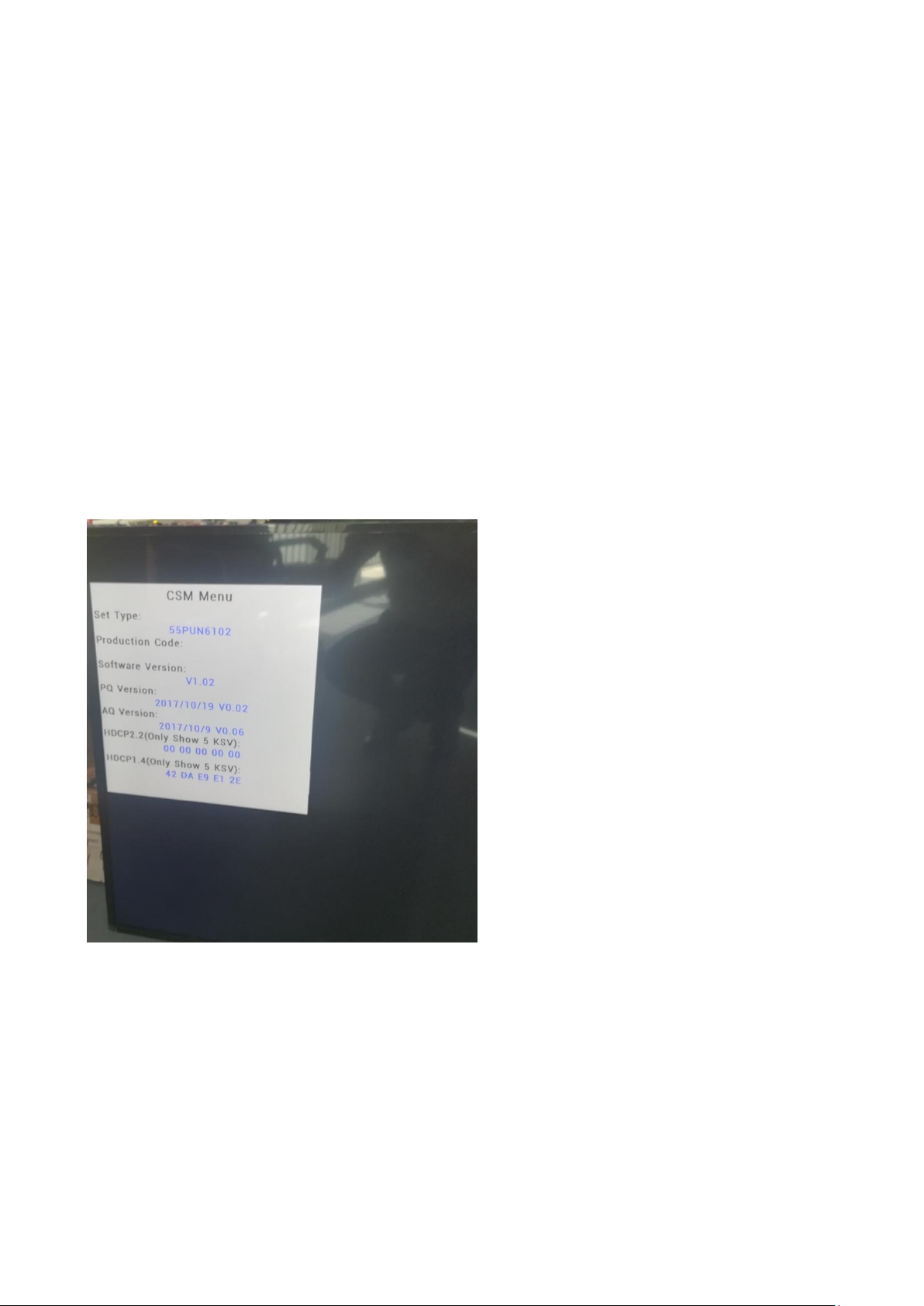
4.3 Customer Service Mode (CSM)
Purpose
The call centre can instruct the customer (by telephone) to enter CSM in order to identify the status of the set. This helps the call centre to diagnose
problems and failures in the TV set before making a service call.
The CSM is a read-only mode, therefore, modifications are not possible in this mode.
How to Activate CSM
To activate CSM, press the following key sequence on a standard remote control transmitter: “menu+456987+back” (do not allow the display to
time out between entries while keying the sequence). After entering the Customer Service Mode, the following items are displayed. Use the
Right/Left keys to display the next/previous menu items
Note: Activation of the CSM is only possible if there is no (user) menu on the screen!
CSM Overview
How to Navigate
By means of the “CURSOR-DOWN/UP” knob (or the scroll wheel) on the RC-transmitter, can be navigated through the menus.
How to Exit CSM
To exit CSM, use one of the following methods.
Press the MENU/HOME button on the remote control transmitter.
Press the POWER button on the remote control transmitter.
Press the POWER button on the television set.
Page 12

5. Software Upgrading, Error code and Panel Code
5.1 Software Upgrading
Step 1: Ready for F/W Upgrade
1. Rename the file to “TPV91H.bin”
2. Prepare a USB memory.
3. Copy the software to USB flash disk (root directory).
4. Switch off the TV and Insert the USB memory stick that contains the software update files in the TV’s USB port
Note the version of this F/W before you change the software file name.
Step 2: F/W Upgrade
1. Power off then power on the TV. The TV will detect the USB memory stick automatically. Then a window jumps out as below:
2. When software update is complete, remove the USB device and press ENTER to restart your TV.
Step 3: Check the SW version
1. After burning software, restart the TV
2. Press “menu+456987+back”, enter Customer service mode to check if the software version is correct
Caution: Please make sure that software upgrade is finished before unplug the USB and AC power!
Page 13

6. Circuit Descriptions
CN102
V By One Output
CN602
Speaker Out
U401
SCALER MSD91H1BN2
U601
AUDIO AD87588
CN101
YPbPr Video In
YPbPr Audio In
Block Diagram
CN601
Line Out
/ Audio Out
FCN101
DTV/ATV In
CN104
S/PDIF
Out
U402
FLASH MX25L6406EM2I-12G
64Mb SOP-8
CN502
HDMI
1 In
U101
Silicon labs
Si2151-A10-GMR
CN503
HDMI
2 In
CN103
USB
In
CN501
HDMI
0 In
6.1 Introduction
The TPS17.3A LA is a new chassis launched in AP in 2017. The whole range is covered by MSD91H platform. The major deltas versus its predecessor
support NTSC Digital TV, with Video out.
The TPS17.3A LA chassis comes with the following stylings:
series xxPUN6102/xx
6.1.1 Implementation
Key components of this chassis are:
SCALER MSD91H1BN2-L-006J S3EPLQFP-156
AUDIO AD87588-LG48NAY 20W E-LQFP-48
FLASH MX25L6406EM2I-12G 64Mb SOP-8
Silicon Tuner Si2151-A10-GMR
6.1.2 Block diagram (For 715G9070M)
Page 14

6.2 Power Supply
Platform
MSD91H
CN701
16V
12V
AUDIO
AMP
LVDS
Display power
CN8603
(for 715G9324P)
CN8601
(for 715G7374P)
Platform power
DIM
ON/OFF
PS_ON
16V
16V_A
PFC
For 50”, 55”
AC-input +
Main filter
AC IN
Power architecture of this platform.
6.2.1 Power Supply Unit
All power supplies are a black box for Service. When defective, a new board must be ordered and the defective one must be returned, unless the main fuse
of the board is broken. Always replace a defective fuse with one with the correct specifications! This part is available in the regular market.
Consult the Philips Service web portal for the order codes of the boards.
Important delta’s with the platform are:
• New power architecture for LED backlight
• “Boost”-signal is now a PWM-signal + continuous variable
The control signals are:
• PS-ON
• Lamp “on/off”
• DIM (PWM) (not for PSDL)
In this manual, no detailed information is available because of design protection issues.
• +16 output (on-mode)
• +16V_audio (audio AMP power)
• Output to the display; in case of
- IPB: High voltage to the LCD panel
- PSL and PSLS (LED-driver outputs)
- PSDL (high frequent) AC-current.
6.2.2 Diversity
The diversity in power supply units is mainly determined by the diversity in displays.
The following displays can be distinguished:
• CCFL/EEFL backlight: power panel is conventional IPB
• LED backlight:
- side-view LED without scanning: PSL power panel
- side-view LED with scanning: PSLS power panel
Page 15

- direct-view LED without 2D-dimming: PSL power panel
+16V_AUD
For SPI Flash
U401 MSD91H1BN2
Q101 AO3407A 4.3A
+1.15V_VDDC
U103 AP1117E33L-13-77 1A
For Reset IC
+1.8V_DDR2
Q702 AO3401 4.3A
U402 MX25L6406EM2I-12G
U701 G5383AQU1U 4A
For Audio Am plifier
U702 AT1529 3.2A
For Panel T-CON Power+16V
U703 AP1117DG-13 1A ADJ 1A
+16V_AUD
U410 G690H293T73
For MSD91H1BN2
For MSD91H1BN2
+5V_Normal
+3.3V_TU
Main Board Power System
U101 Si2151-A10-GMR
U601 AD87588
12V-Panel
+5V_Standby
+3.3V_Standby
For MSD91H1BN2U704 AP1117E33L-13-77 1A U401 MSD91H1BN2
U401 MSD91H1BN2
For TUNER 3.3V
U106 SY8366QNC 6A
U601 AD87588 For AMP 3.3V
- direct-view LED with 2D-dimming: PSDL power panel.
PSL stands for Power Supply with integrated LED-drivers.
PSLS stands for a Power Supply with integrated LED-drivers with added Scanning functionality (added microcontroller).
PSDL stands for a Power Supply for Direct-view LED backlight with 2D-dimming.
6.3 DC/DC Converters
The on-board DC/DC converters deliver the following voltages(depending on set execution):
• +5V-SB, permanent voltage for the Stand-by Power systemI
• +3V3-STANDBY,voltage for IR/Key board
• +16V, input from the power supply for the panel common(active mode)
• +12V, for the panel common(active mode)
• TUNER_3V3, supply voltage for tuner
• +5V, input intermediate supply voltage for USB Power
• +12V-AUDIO1 for the AUDIO AMP
• +3.3VA_T2, +1.2V_T2 voltage for Demodulator IC channel decoder
6.3.1 Power tree (For 715G9070M)
Page 16

6.3.2 Power layout SSB
C165 +3.3V_TUN
L702 +1.15V_VDDC
L701 +5V_SB
C729 +1.8V_DDR2
C732 +3.3V_SB
Power SSB Top View (For 715G9070M)
6.4 Video and Audio Processing - MSD91H1BN2
The MSD91H1BN2-L-006J S3EPLQFP-156 is the main audio and video processor (or System-on-Chip) for this platform. It has the following features:
1. Digital and Analog TV Front-End Demodulator
2. Multi-Standard A/V Format Decoder
3. The MStarACE6uc Video Processor
4. Home Theater Sound Processor
5. Embedded Memory for optimized BOM cost
6. Multiple HDMI 2,0/1.4 b Compliant Ports with ARC Support
7. One MHL 2.2 Compliant Port
OVERVIEW
MSD91H1BN2 is a highly integrated TV SoC solution for ATSC digital television platform. Integrating latest advanced technologies from MStar
Semiconductor, the world leading TV SoC provider in TV industry, MSD91H1BN2 provides the most cost-efficient solution for multimedia TV application
with creative and attractive features exclusively presented.
In order to achieve the lowest BOM cost in a multi-media TV platform, MSD91H1BN2 integrates DTV, ATSC/QAM demodulator, TV/multi-media all-purpose
AV decoder, VIF demodulator, and advanced Sound/Video processors into a single device. This not only reduces the overall BOM significantly, but also
facilitates the design of originally-complicated TV systems for developers. In addition, the memory-embedded solution provided by MSD91H1BN2 can
reduce the excessive work of memory interface routing on board and the risk of memory performance degradation while powering cost-down in the total
system.
The powerful multimedia A/V decoder inside MSD91H1BN2 is hosted with a dedicated hardware video codec engine to secure fast and stable video
Page 17

streaming playback. Moreover, MSD91H1BN2 is equipped with a DSP specifically designated for audio application, including digital audio format decoding
and advanced sound effects, and a high performance RISC CPU to manipulate all possible routines and house-keeping activities. With extendable USB 2.0
interface, an MSD91H1BN2 based system can turn into a high quality media-center in a simple manner.
MSD91H1BN2 supports the latest MHL technology, which allows user to stream audio and full HD video from mobile devices to televisions. Power
management and low-power design of MSD91H1BN2 makes it possible to charge MHL devices even in standby mode. The MHL/HDMI dual-purpose port
on MSD91H1BN2 will enable charging if MHL devices are automatically detected.
For standard users, the MSD91H1BN2 provides multi-standard analog TV support with adaptive 3D video decoding and VBI data extraction. The built-in
audio decoder is capable of decoding FM, AM, A2, BTSC and sound standards. MSD91H1BN2 also supplies all the necessary A/V inputs and outputs to
complete a receiver design including HDMI receivers and component video ADCs. All input selection multiplexers for video and audio are integrated,
including full SCART support with CVBS output. The equipped MStar MStarACE-6 color engine is the latest masterpiece of MStar technologies, providing
excellent video and picture quality in Full-HD and large-scale display system. MSD91H1BN2 also supports an ultra low power standby mode to meet the
latest energy legislative requirements without any additional hardware.
Page 18

7. IC Data Sheets
7.1 MSD91H (IC U401)
Page 19

7.2 AD87588-LG48NAY (IC U601)
Page 20

7.3 Si2151-A10-GMR (IC U101)
Page 21

8.Circuit Diagrams
C9912
22PF 250V
BR
!
!
!
!
!
N
SG9902
500V
T5AH/250V
CN9903
NC
L1N
2
L
SG9901
500V
L9903
0.25mH
1
2
4
3
!
C9901
470NF 275V
!
CN9902
NC
1
2
C9902
470NF 275V
!
!
!
!
!
!
!
!
!
!
!
!
HS9901
HEAT SINK
1
2
CN9901
AC 2P
12
-
+
BD9901
TS25P06G-06
2
1
3
4
R9905
510K
R9904
510K
R9902
510K
U9901
NC
NC
1D12D13NC4
NC5D26D27NC
8
!
C9908
NC
R9907
510K
CN9904
NC
12
N
R9903
510K
R9906
510K
L
L9901
12mH
1
2
4
3
Vsin
L9902
12mH
1
2
4
3
For BD9901
RV9901
680V
F9901
FUSE
1 2
3 4
C9911
22PF 250V
F9902
NC
t
NR9901
NTCR 3.6W
12
t
NR9902
NTCR 3.6W
12
t
NR9903
NTCR 3.6W
1 2
!
!
C9914
220PF 250V
C9913
220PF 250V
T5AL/250V
FB9901
BEAD
12
FB9902
BEAD
12
8.1 A 715G7374 PSU (For 55” 6102 Series)
8-1-1 AC Input
Page 22

8-1-2 PFC-LD7591T
R9817
NC
L9801
170uH
1 4
63
R9807
2K 1% 1/8W
R9816
NC
!
FB9802
BEAD
12
FB9804
BEAD
1 2
C9814
NC
R9819
0R05 1/4W
R9815
30K 1/8W 1%
C9815
0.1uF 50V
C9816
0.1uF 50V
R9818
0R05 1/4W
C9813
0.47UF 50V
C9809
0.1uF 50V
C9812
47nF 50V
C9802
10NF 1KV
R9812
470R 1%
C9806
1uF 450V
Q9801
IPA60R230P6
2
1
3
C9807
47PF 50V
+
C9803
68uF 450V
R9802
10 OHM 1/4W
R9814
10K 1/8W
+
C9804
68uF 450V
R9805
10K 1/8W
D9802
FMNS-1106S
C9801
47PF 1KV
U9801
LD7591T
INV1COMP2RAMP3CS
4
ZCD
5
GND
6
OUT7VCC
8
C9810
470PF 50V
C9811
1NF
R9804
1M 1% 1/4W
R9811
19K1 +-1% 1/8W
R9801
0R05
R9806
1M 1% 1/4W
R9810
1M 1% 1/4W
FB9805
BEAD
1 2
R9803
33ohm 1/4W +/-5%
R9808
0.15R
R9809
0.15R
HS9801
HEAT SINK
1
2
3
4
For Q9801/D9802
+VCC1
U9802
NC
ISEN
1
GND
2
VSEN3IREF
4
OUT
5
VCC
6
R9821
NC
R9824
NC
R9822
NC
R9823
NC
C9821
NC
D9810
NC
R9825
NC
C9820
NC
PFC_OVP
Q9802
NC
3
1
2
C9818
470PF 250V
ZD9801
NC
1 2
HV_A
VCC_ON
R9813
24KOHM +-1% 1/8W
D9804
IN4148W RHG
For Power Sav ing
D9805
IN4148W RHG
C9819
1uF 450V
D9806
IN4148W RHG
VCC_ON
C9817
47PF 1KV
HV
Vsin
FB9801
BEAD
1 2
+
C9808
10UF 50V
D9801
S8KC
D9803
S8KC
Page 23

8-1-3 Standby-SSC3S121
ZD9105
BZT52-B39
1 2
R9141
9.1K 1%
R9134
27 OHM 1/4W
ZD9102
BZT52-B20
1 2
R9162
1.5K OHM
CN9103
CONN
2
4
6
8
10
12
14
16
1
3
5
7
9
11
13
15
C9106
0.1uF 50V
R9111
200 OHM 1/4W
R9118
20K 1/8W 1%
D9102
FR107G-A0
R9133
27 OHM 1/4W
Q9107
2N7002K
C9140
1uF
R9166
0R05
R9109
10R 1/8W 5%
L9102
3UH
U9102
EL817M(X)
12
43
C9143
1N 50V
R9117
3K
R9131
27 OHM 1/4W
C9142
1uF
C9103
NC
Q9106
BTC4672M3
R9130
27 OHM 1/4W
C9102
2.2NF
L9103
3UH
R9132
27 OHM 1/4W
R9135
27 OHM 1/4W
C9101
1000PF
R9161
510K 1% 1/8W
ZD9101
BZT52-B16
1 2
R9137
0 OHM +-5% 1/8W
+
C9113
10UF 50V
R9145
1K 1/8W 1%
R9110
10K 1/8W
C9129
0.1uF 50V
+
C9144
NC
+12V_A/+16V_A
+12V/+16V
BL_ON/OFF
+12V_A/+16V_A
+12V/+16V
DV5
+VCC1
+12V_A/+16V_A
+12V/+16V
DIM
PS_ON
PS_ON
NC
12VS
12VS
12VS
12VS
HV
VCC_ON
!
!
!
!
R9119
33 OHM
COLD
HOT
For Q9101
筿溃(14V).
R9112
0.24R
D9103
SARS01-V1
C9130
1nF 250V
C9131
1nF 250V
R9101
4.7M OHM +-5% 1/4W
+
C9126
220uF 25V
R9107
2 OHM 1%
U9104
TL431G-AE2-R
+
C9127
220uF 25V
HS9103
HEAT SINK
1
2
3
4
R9163
10K 1/8W 1%
D9106
FME-220B
1
2
3
D9108
FME-220B
1
2
3
D9107
FME-220B
1
2
3
C9145
NC
+VCC1
U9106
EL817M(X)
12
43
D9114
IN4148W RHG
D9104
IN4148W RHG
R9140
9.1K 1%
+VCC1
C9141
1uF
R9164
3K
R9146
2.2K 1/4W
C9110
4.7uF 10V
R9160
100 OHM 1/4W
+
C9147
NC
+
C9148
NC
HS9101
HEAT SINK
1
2
3
4
D9101
SARS01-V1
DV5
R9139
100K 1/8W 1%
R9138
100K 1%
R9142
1.5KOHM
R9105
82K 2W
C9111
4.7nF 50V
C9139
0.47UF 50V
PFC_OVP
R9143
470R 1/8W 1%
R9106
33 OHM
!
T9101
NC
1
2
3
5
6
7
9
10
4
U9101
SSC3S121A
FB/OLP
1
BR
2
ST4DRV
5
OCP
6
VCC
7
GND
8
Q9109
2N7002K
C9108
470PF 50V
C9138
0.1uF 50V
FB9102
BEAD
12
FB9101
BEAD
1 2
Q9108
MMBT3906
BR
+
C9104
100UF 50V
C9115
1NF 250V
C9107
47PF 1KV
R9113
0R05
Q9101
TK13A65U
T9102
X'FMR 300uH
1
2
3
5
6
7
10
12
4
8
11
9
R9103
620K +-1% 1/4W
R9116
0R05
R9136
NC
R9147
2K2 1/8W 5%
R9108
82 OHM
R9104
620K +-1% 1/4W
R9144
NC
+
C9146
2200uF 25V
LED_OVP
R9115
51K +-5% 1/8W
R9114
620K +-1% 1/4W
HV_A
R9165
2K 1/8W 1%
ZD9104
BZT52-B39
1 2
Page 24

8-1-4 LED-SSC9522S+TPV101A or C
U8621
EL817M(X)
1
23
4
C8614
560PF 50V
D8609
IN4148W R HG
LED_VCC
R8658
NC
R8610
47K 1/8W 1%
C8613
1N 50V
D8612
IN4148W R HG
Q8602
TK10A50D
!
T8601
X'FMR 310uH 50:10 for 40V Backlight
1
5
6
8
9
10
11
12
7
4
Q8601
TK10A50D
COMP
D8613
IN4148W R HG
R8670
NC
ZD8607
BZT52-B7V5
1 2
R8653
11K 1/8W 1%
D8610
NC
ZD8610
NC
1 2
ZD8606
BZT52-B7V5
12
C8615
100PF 1KV
Q8609
MMBT3906
ZD8613
BZT52-B30
1 2
Q8607
NC
R8601 0.1R 1W
R8635
1oHM 1% 1/4W
R8640
47K 1/8W 1%
ZD8605
BZT52-B3V6
1 2
Q8606
NC
R8624
0R05
ZD8614
BZT52-B30
1 2
R8636
1oHM 1% 1/4W
R8667
JUMP
U8604
TL431G-AE2-R
R8641
47K 1/8W 1%
R8627
0R05
C8628
0.1uF 50V
R8637
1oHM 1% 1/4W
D8614
MBRF10150CT
1
2
3
D8616
MBRF10150CT
1
2
3
R8613
10R 1/8W 5%
+12V/+16V
R8671
0R05 1/4W
+
C8620
NC
R8629
0R05
R8662
1.2R 1%
R8611
10R 1/8W 5%
+
C8621
220uF 100V
HS8601
HEAT SINK
1
2
R8663
1oHM 1% 1/4W
+
C8623
47uF 100V
HS8602
HEAT SINK
1
2
Q8608
MMBT3904
C8616
100PF 1KV
R8664
1oHM 1% 1/4W
ZD8615
NC
1 2
C8618
NC
R8659
JUMPER
R8673
0 OHM 1/8W
C8624
4.7UF
LED_OVP
R8665
1oHM 1% 1/4W
R8666
NC
C8648
NC
C8637
4.7UF
R8655
JUMP
R8643
0 OHM +-5% 1/8W
R8661
1.2R 1%
R8660
0 OHM +-5% 1/8W
R8657
NC
C8639
0.1uF 50V
R8656
NC
C8638
NC
R8652
NC
-VLED-2
C8611
5PF
D8615
NC
1
2
3
For D861 4/D861 5/D861 6
LED_VCC
R8686
0R05 1/4W
R8687
0R05 1/4W
R8688
0R05 1/4W
ZD8604
NC
12
ZD8603
NC
1 2
ZD8602
NC
12
U8601
SSC9522S
Vsen
1
Vcc
2
FB
3
GND
4
Css
5
OC
6
RC
7
Reg
8
RV9COM
10
VGL
11
NC
12
NC
13
VB
14
VS
15
VGH
16
NC
17
NC
18
R8642
7K5 1/8W +/ -1%
ZD8601
BZT52-B15
1 2
C8640
NC
HS8603
HEAT SINK
1
2
3
4
C8634
0.1uF 50V
C8608
0.47UF 50V
LED_VCC
DIM
+12V/+16V
R8668
100K
C8606
10N 50V
C8633
0.1uF 50V
C8603
0.1uF 50V
C8612
1uF
R8602 1M5 1/4W 1%
C8630
NC
C8607
4.7uF 10V
L8601
3UH
C8627
100PF 50V
C8609
1UF
DIM
R8605
18K 1/8W 1%
LED_VCC
R8612
47 +-5% 1/8W
R8614
10K 1/8W 1%
R8617
10K 1/8W 1%
C8604
0.1uF 50V
C8631
NC
C8617
33nF
R8672
NC
Option LED_VCC控制迴路,搭 配TPV111D使用!!
C8610
NC
R8618
270R 1%
R8615
47 +-5% 1/8W
R8620
NC
C8601
1000PF
VBoot
VBoot
+VLED
HV
VCC_ON
VLED
R8609
470 OHM 1/4W
!
R8603
1M5 1/4W 1%
!
+VLED
CN8601
CONN
1
2
3
4
5
6
7
8
9
10
11
12
-VLED-1
+VLED
-VLED-2
U8605
NC
IN
3
OUT
1
GND
2
R8634
1.2R 1%
R8604
1M5 1/4W 1%
GND5
GND
1
ZD8608
NC
1 2
R8632
1K 1/8W 1%
R8674
NC
R8646
NC
R8631
5.1KR 1%
R8644
2K 1/8W 1%
C8632
0.1uF 50V
R8647
1K 1/8W 1%
+12V/+16V
VLED
DV5
ZD8609
BZT52-B33
1 2
20150917 add.
Q8604
NC
C8636
NC
Q8605
NC
C8635
NC
R8654
NC
R8649
NC
R8650
NC
BL_ON/OFF
R8616
10 OHM 1/4W
R8639
1K 1/8W 1%
C8602 NC
VCC_ON
R8608 NC
R8607
NC
R8606
0R05 1/4W
C8647
NC
R8622
JUMP
U8602
TPV101AD
DIM
1
EN
2
VCC
3
LED4GND
5
ISET
6
GM
7
COMP
8
R8621
NC
R8623
NC
R8625
NC
R8633
1.2R 1%
R8628
0 OHM +-5% 1/8W
C8625
NC C8626
0.1uF 50V
-VLED-1
U8603
TPV101AD
DIM
1
EN
2
VCC
3
LED4GND
5
ISET
6
GM
7
COMP
8
R8638
1.5K OHM
ZD8612
NC
1 2
R8648
1Kohm +-1% 1/4W
ZD8611
NC
1 2
R8651
NC
D8603
UF4007
BL_ON/OFF
R8645
39K 1/8W 1%
R8669
0R05 1/4W
VLED
R8630
0R05
BL_ON/OFF
C8629
NC
R8619
470OHM +-5% 1/8W
D8601
IN4148W R HG
COMP
Q8603
NC
3
1
2
D8602
IN4148W R HG
LED_VCC
+C8605
10UF 50V
GND2
NC
1
GND1
NC
1
GND4
GND
1
D8611
NC
GND3
GND
1
COMP
R8626
NC
Page 25

8.2 A 715G9324 PSU (For 50” 6102 Series)
F9902
FUSE
12
34
!
!
!
!
!
!
!
!
!
!
!
!
!
!
!
!
!
!
!
FB9903
127R
1 2
C9902
220NF 305V
C9911
22pF 5% 250V
X90G20100080000ABF : 52mm*10mm
X90G201001500000HG : 52mm*20mm
For BD9901
C9912
22pF 5% 250V
!
!
!
R9902
510K 1/4W
!
!
!
!
R9903
510K 1/4W
R9904
510K 1/4W
R9905
510K 1/4W
R9906
510K 1/4W
C9900
NC / 47pF
L
N
R9901
510K 1/4W
U9901
NC
1L12L13NC4
NC5L26L27NC
8
Rsen-
D9901
PG4007
BR
GND2
1
GND1
1
L9902
8mH
1
2
4
3
CN9901
NC /CONN
1
2
F9901
NC / 5A 250V
CN9902
AC 2P
12
C9914
220PF 250V
C9901
470nF 275V
L9901
8mH
1
2
4
3
C9913
220PF 250V
L
VSIN
T5AH/250V
!
HS9901
NC / HEAT SINK
1
2
N
SG9902
DSPL-501N-A21F
FB9904
127R
1 2
C9915
220PF 250V
FB9905
127R
1 2
RV9901
680V
L9903
0.25mH
1
2
4
3
C9916
220PF 250V
t
NR9901
NTCR 5R
12
C9917
220PF 250V
t
NR9902
NTCR 5R
12
t
NR9903
NTCR 5R
12
t
NR9904
NTCR 5R
12
SG9901
DSPL-501N-A21F
HS9902
NC / HEAT SINK
1
2
-
+
BD9901
TS10P06G-05
2
1
3
4
8-2-1 AC Input
Page 26

8-2-2 PFC with LD7592GS
R9801
18K OHM 1% 1/8W
R9808
0R2 5%
D9801
FMNS-1106S
C9800
1UF 450V
C9813
0.47UF 50V
Q9801
TK13A60D
2
1
3
Q9802
MTN127KN3
D9805
SS1060FL
R9805
10K OHM
FB9802
BEAD
1 2
R9816
100K 1/8W
R9806
300K OHM 1%
C9804
47PF
D9802
NC / S8KC
+
C9802
56UF 450V
R9814
10K 1/8W 1%
D9804
SS1060FL
D9803
NC / S8KC
R9803
0.005R 1%
R9804
2.7M 1%
R9802
27R 1%
C9810
1NF 50V
HS9801
HEAT SINK
1
2
3
4
R9899
3.4K 1%
C9812
47N 50V
U9801
LD7592
INV1RAMP2COMP3CS
4
OVP
5
GND
6
OUT7VCC
8
R9813
24K 1/8W 1%
Q9803
MMBT2907A
R9832
0R05
C9817
100PF
C9814
100P 50V
C9808
10uF 25V
C9809
100N 50V
+
C9801
56UF 450V
R9818
NC
R9817
10K OHM
PFC_VCC
HV
Rsen-
Vsin
PFC_VC
PFC_VC
L9801
300uH
5
4
1
3
For Q9801
L9802
NC / 300uH 10%
1
3 4
5
150W:
Full - 47*2
HV - 56*1
120W:
Full - 56*1
HV - 47*1
FB9801
127R
1 2
R9809
0R2 5%
+
C9811
47uF 50V
R9819
1K OHM 1% 1/8W
Page 27

8-2-3 LLC with SSC3S927
C9103
2.2NF
REG
BR
R9101
2.7M 1%
+16V
C9118
0.47uF 50V
R9107
NC
R9165
0 OHM 5% 1/8W
R9166
100K 1/8W 1%
REG
R9131
0R05
+
C9121
330UF 35V
R9130
0R05
+
C9122
330UF 35V
!
!
!
C9124
1UF 50V
D9122
FCHS30A08
1
2
3
C9189
100N 50V
R9181
100 OHM 1%
+16V_A
DV5
R9182
510K 1% 1/8W
R9183
15K 1/4W 1%
Q9181
2N7002K
C9119
100PF
4A
2.75A/1.75A
C9125
100nF 50V
1A/0.7A
!
!
+
C9127
470UF 25V
new parts!!
PSU: BCK-13918-HA
LPB: BCK-13921-HA
Q9142
MMBT3906
+
C9126
470UF 25V
ZD9153
BZT52-B18G
1 2
U9103
EL817M(X)
12
43
T9101
Lp=700uH, Lk=180uH
2
6
8
9
10
11
12
13
5
14
4
7
R9118
10 OHM 1% 1/8W
U9104
EL817M(X)
12
43
HOT COLD
C9918
10N 50V
40mm * 35mm
For D9122 & D9124
STB
Q9141
2N7002K
PS_ON
Q9105
BTC4672M3
R9144
1K5 1% 1/8W
C9141
100N 50V
ZD9141
BZT52-B15
1 2
R9103
68K 1/8W 1%
R9143
10K 1/8W 1%
R9141
100 OHM 1%
R9145
10K OHM
12VS
R9147
47K 1/8W 1%
R9148
10K OHM
R9105
130R 1%
DV5
R9142
510K 1% 1/8W
R9146
2Kohm 1/4W +/-1%
16VS
R9154
9.1K 1% 1/8W
C9108
220N 50V
R9114
100 OHM 1%
C9117
220N 50V
U9101
SSC3S927
VSEN
1
VCC
2
FB
3
ADJ
4
CSS
5
CL
6
RC
7
CD
8
SB9GND
10
VGL
11
REG
12
NC
13
VB
14
VS
15
VGH
16
NC
17
ST
18
R9108
4.7R 1%
C9148
100NF 50V
+20V
C9172
100N 50V
D9124
FCHS30A08
1
2
3
ZD9152
BZT52-B16
1 2
D9123
FCHS30A08
1
2
3
C9173
100N 50V
+12V / +16V
C9180
220NF 50V
C9157
1UF 50V
Q9106
MMBT3906
+12V_A / +16V_A
Q9107
BC847C
55mm * 18mm
For D9121 & D9123
PS_ON
HS9111
HEAT SINK
1
2
3
4
+
C9116
220uF 50V
C9102
2.2nF 50V
D9105
FR107G-A0
R9123
1K 1%
R9124
1K 1%
BL_ON/OFF DIM
R9156
3K3 1/8W 1%
R9163
0R05 1/8W
C9156
47N 50V
C9155
1N 50V
R9157
82K 1%
R9164
2K 1% 1/8W
R9102
2Mohm 1/4W +/-1%
C9153
100N 50V
R9161
4K7 1/8W 1%
R9110
1.5Mohm 1/4W +/-1%
R9158
0 ohm
C9152
NC/47N 50V
C9100
NC / 1.5NF
R9169
100K 1/8W 1%
R9160
12K 1/8W 1%
+20V
L9133
1.1uH
R9162
1K5 1% 1/8W
Q9151
2N7002K
D9102
NC / SR34H
1 2
16VS
R9152
510K 1% 1/8W
R9151
100 OHM 1%
C9151
100N 50V
R9153
10K 1%
DV5
16VS
CN9101
CONN
2
4
6
8
10
12
14
16
1
3
5
7
9
11
13
15
R9168
2K2 1/8W 1%
NC / FB9101
BEAD
1 2
HS9121
HEAT SINK
1
2
3
4
R9122
NC / 10M
U9150
AS431AN-E1
R9113
100K 1/8W 1%
C9104
10N 50V
R9116
10K 1/8W 1%
D9101
UF1010G
VCC1
D9104
IN4148W R HG
Q9102
IPA50R800CE
2
1
3
C9107
220P 50V
R9119
10K 1/8W 1%
ZD9101
BZT52-B15G
12
R9106
120R 1/8W 1%
C9109
10N 50V
C9131
22UF 25V
R9159
1.74K 1/8W 1%
D9902
1N4148W
C9105
220NF 50V
C9115
2U2 25V
C9106
0.47UF 50V
R9104
NC
R9109
4.7R 1%
C9112
15nF
C9114
0.1uF 50V
C9101
NC / 1NF
R9120
2.2R 1%
C9113
100PF
C9111
100PF
D9103
IN4148W R HG
Q9101
IPA50R800CE
2
1
3
R9117
100 OHM 1%
HV
C9133
22UF 25V
ZD9142
BZT52-B6V2
1 2
3.75A
COLDHOT
C9919
10N 50V
+12V / +16V
+12V_A / +16V_A
PFC_VCC
R9115
10 OHM 1% 1/8W
D9121
FCHS30A08
1
2
3
ADJ
REG
Q9104
MMBT3906
D9125
NC / FCHS30A08
1
2
3
C9110
4N7 50V
FB_LLC
R9111
10K 1%
R9112
100K 1/8W 1%
R9184
15K 1/4W 1%
FB_LLC
ADJ
VCC1
R9167
200K 1% 1/8W
Page 28

8-2-4 Driver with OZ9902C
+VLED
-VLED
R8613
300K 1/8W
C8624
100NF 50V
R8609
18K 1/8W 1%
C8604
10NF 50V
C8608
1N 50V
R8619
1K 1/8W 1%
C8611
100P 50V
L8603
NC / BOOST CHOKE
8
1
4
6
R8607
16K 1% 1/8W
R8616
56K 1/8W +/-1%
R8605
10 OHM 1%
C8610
1NF 50V
D8602
NC
C8601
10uF 50V
C8602
10uF 50V
C8617
10uF 50V
R8630
1.2R 1%
R8637
1R 1%
R8628
1.2R 1%
R8638
1.2R 1%
R8627
1.2R 1%
A GND
HS8601
HEAT SINK
1
2
3
4
Closed to B GND
Closed to B GND
Closed to B GND
CN8603
CONN
1
2
3
4
5
6
7
8
9
10
11
12
A GND
55mm * 35mm
For Q8601 D8601
B GND
32V/2.5A
Co-Lay
U8601
OZ9902CGN
UVLS
1
VCC
2
ENA
3
VREF
4
RT
5
PWM
6
ADIM
7
TIMER8SSTCMP
9
ISEN
10
PROT
11
ISW
12
OVP
13
GND
14
DRV
15
FAULT
16
R8612
4K7 1/8W 1%
R8610
10 OHM 1% 1/ 4W
+
C8612
220uF 50V
C8606
1N 50V
R8611
91K 1%
C8609
1UF
R8634
1R 1%
+
C8614
220uF 50V
R8636
1.2R 1%
C8620
1NF
R8606
120K OHM 1%
R8623
100 OHM 1%
R8621
10K 1/8W 1%
R8626
10K 1/8W 1%
+
C8613
220uF 50V
C8616
47PF
D8603
NC / BAV70
3
1
2
L8602
3UH
R8629
NC / 100K 1/8W 1%
R8631
56K
+
C8622
220uF 50V
C8605
2.2UF 25V
R8632
1.2R 1%
C8615
NC / 100N 50V
R8614
4K7 1/8W 1%
C8603
1UF
L8601
33uH
2
1
R8608
56K
R8635
1.2R 1%
C8607
2.2UF 25V
R8601
0R03 5%
R8615
100K 1/8W 1%
Q8601
TK22A10N1
D8601
FCHS30A08
1
2
3
R8622
10K 1/8W 1%
C8619
100P 50V
R8618
100K 1/8W 1%
R8603
1K 1/8W 1%
R8604
0.005 OHM 1% 1/2W
+VLED
-VLED
BL_ON/OFF
+20V
DIM
16VS
R8633
1.2R 1%
Closed to B GND
R8617
100K 1/8W 1%
MTD030N10QJ3 100V
Q8602
1
3 2
FB8601
BEAD
1 2
Page 29

8.3 B 715G9070 SSB
E
A
B
C
D
CN101
RCA JACK 10P
1
2
3
4
5
6
7
8
9
10
YPBPR_L_IN#1
YPBPR_R_IN#1
SPDIF_OUT
PB_IN#1 COMP_PB
Y_IN#1
PR_IN#1
COMP_Y
COMP_PR
COMP_COM
SPDIF
R112
75R 1/16W 1%
R134 33R 1/16W 5%
R102
150 OHM 5% 1/16W
R103
180R 1/16W 5%
Nearly IC
C139 47NF 16V
C108 47NF 16V
C143 47NF 16V
Connected to connector GND
Nearly Connector
R115
75R 1/16W 1%
R131
75R 1/16W 1%
R137 68R 1/16W 5%
C104 47NF 16V
R110 33R 1/16W 5%
C107 47NF 16V
C151 47NF 16V
R130 33R 1/16W 5%
+5V_Normal
COMP_PR 6
COMP_Y 6
COMP_COM 6
COMP_PB 6
CVBS_VCOM 6
CVBS0P 6
SPDIF_OUT6
C127
330pF 50V
CN104
FIBER-OPTIC 5P
GND
1
VCC
2
VIN
3
TH1
4
TH2
5
388G359G09A0YG000A
CVBS0PAV1_IN
CVBS_VCOM
HD_LIN
C101
3N3 50V
C115
3N3 50V
ZD101
NC/VPORT0603100KV05
R120
0R05 1/16W
ZD104
NC/VPORT0603100KV05
C126
100NF 16V
R121
33R 1/16W 5%
PR_IN#1
PB_IN#1
Y_IN#1
YPbPr Video Input share with CVBS in Y
NEARLY CONN.
Change CONN 088G 78G154AYG. 20170216
ZD102
NC
12
ZD105
NC
12
ZD106
NC
12
R107 10K 1/16W
R113
12K 1%
R114
12K 1%
R109 10K 1/16W
HD_LIN 6
HD_RIN 6
HD_RIN
8-3-1 AV/YPbPr/SPDIF
Page 30

8-3-2 Tuner In/Debug
C102
1.2nF 50V
C135
39PF 50V
DIFP 6
DIFM 6
R150
0R05 1/16W
R151
0R05 1/16W
R154 33R 1/16W 5%
R156 33R 1/16W 5%
Q109
MMBT3904
IF_FAT_N
R192
NC/4. 7K 1/16W
R193
NC/4. 7K 1/16W
IF_FAT_N
IF_FAT_IN -
IF_FAT_IN +
+5V_Standby
L104
270nH
L105
270nH
IF_FAT_P
IF_FAT_P
L106
270nH
U103
G1117-33T63Uf
VI3VO
2
GND14
4
R192,R193--> NC
+3.3V_TU
R126
0R05 1/16W
R135
0R05 1/16W
C134
NC
C138
33pF 50V
C145
100NF 16V
R146
100R 1/16W 1%
R101
0R05 1/16W
R186
NC
R136
0R05 1/16W
C140
33pF 50V
C148
NC
C144
100NF 16V
R127
0R05 1/16W
R147
100R 1/16W 1%
R153 0R05 1/16W
C167
39PF 50V
C166
39PF 50V
C163
100NF 16V
C162
10UF 10V
R155 0R05 1/16W
L102
180nH
D101
NC/BAV99
3
1
2
C141
47pF 50V
U104
SN74LVC1G3157DC KR
B2
1
GND
2
B13A
4
VCC
5
S
6
L103
270nH
C165
10UF 6. 3V 20%
R149
0R05 OHM
IF-AGC 6
IF-AGC
C164
100NF 16V
U105
SN74LVC1G3157DC KR
B2
1
GND
2
B13A
4
VCC
5
S
6
+5V_Normal
+5V_Standby
+3.3V_TA +3.3V_TU
I2C-SCL 6,7,8
DEBUG_CK5
I2C-SDA 6,7,8
DEBUG_DA5 DDCA_D A 6
DDCA_C K 6
HDMI3-DD C-SDA 5
HDMI3-DD C-SCL 5
IF_FAT_IN -
IF_FAT_IN +
R196 1K 1/16W
R191
47K 1% 1/16W
S
ON Channel
I2C Interface Filterr- Close to Tuner
Select function
3V3T / 200mA
Debug
H
TUNER POWER +3V3
HDMI 3
B1
C175
1.2nF 50V
B2
L
L101
270nH
75 ohm line
C177
100NF 16V
Silicon Tuner
388G510F501AHC
388G510F501ACL
T_SDA
T_SCL
Si2151-A10-GMR
U101
SDA
2
AGC1
5
NC
18
GND
8
+1.8V
7
LIF_N
10
LIF_P
11
GPIO1
24
SCL
3
+3.3V
9
AGC2
4
+3.3V
15
XOUT
12
XTAL_I/RCLK
13
XTAL_O
14
GND
6
+3.3V
17
RF_REF
19
RF_IP
20
RF_IN
22
ADDR
23
GND(EPAD)25GND16GND
21
GPIO2
1
R142
0R05 OHM
C176
180pF 50V
IF Interface Filter- Close to Scaler
IF Interface Filter- Close to Tuner
T_SCL
T_SDA
C195
22P 50V
ZD108
RLZ9V1B
1 2
DEBUG_P14
R194
1K 1/16W
R190
4.7K 1/16W
R104
47K 1/16W
C196
100nF 16V
R195
NC/0R05 1/16W
C142
NC C147NC
TU111
RF C ONN
1
1
2
2
3
3
4
4
ANT
5
C161
22NF25V
+5V_Standby
I2C-SCL
I2C-SDA
C159
1UF 10V
C103
1.2nF 50V
C137
1.2nF 50V
C157
1.2nF 50V
Debug_EN6
X102
24MHz
1
24
3
+3.3V_TU
C136
39PF 50V
DEBUG_P145
Page 31

8-3-3 HDMI INPUT
R524 0R05 1/10W
HDMI2/5V
C509
100NF 16V
R501 0R05 1/10W
R547
33R 1/16W 5%
CEC
C501
100NF 16V
R538
NC/10K
DEBUG_P14 4
DEBUG_P14
ZD504
NC
1 2
C513
1uF
HDMI2-CLKP 6
HDMI2-SDA 6
HDMI2-RX1P 6
HDMI2-RX2P 6
HDMI2-RX0P 6
HDMI2-RX2N 6
HDMI2-SCL 6
HDMI2-RX0N 6
HDMI2-CLKN 6
HDMI2-RX1N 6
Q503
2N7002K
R525
10K 1/16W 5%
R508
NC/4K7 1/16W 5%
HDMI3-RX2P 6
HDMI3-RX1N 6
HDMI3-RX0N 6
HDMI2-HPD IN
R510
4K7 1/16W 5%
HDMI3-CLKN 6
HDMI3-SCL 6
HDMI3-SDA 6
R509
1K 1/16W 5%
HDMI3-RX2N 6
HDMI3-RX1P 6
HDMI3-CLKP 6
HDMI2/5V
HDMI3-RX0P 6
HDMI2-RX1N
HDMI2-RX0N
HDMI2-RX2N
HDMI2-RX1P
HDMI2-RX2P
HDMI2-CLKN
HDMI2-RX0P
HDMI2-CLKP
2/7
そ 絬隔
2/7
そ 絬隔
R536
100R
R516
10 OHM
There are weak p ull low R at HDMI P ortA/B/C/D power
detect pins, s o it wou ld not floatin g if cable not
R526
10 OHM
HDMI0/5V
HDMI2 (HDMI 2.0)
CEC & ARC
2/7
そ 絬隔
CN503
HDMI 19P
SHLD0
20
SHLD1
21
TMDSD2+
1
DSHLD0
2
TMDSD2-
3
TMDSD1+
4
DSHLD1
5
TMDSD1-
6
TMDSD0+
7
DSHLD2
8
TMDSD0-
9
TMDSC+
10
CSHLD0
11
TMDSC-
12
CEC
13
NC
14
SCL
15
SDA
16
DDC_GN D
17
VCC5
18
HPD
19
SHLD2
22
SHLD3
23
2/7 DELETE
MHL
R541
100R
CN501
HDMI 19P
SHLD0
20
SHLD1
21
TMDSD2+
1
DSHLD0
2
TMDSD2-
3
TMDSD1+
4
DSHLD1
5
TMDSD1-
6
TMDSD0+
7
DSHLD2
8
TMDSD0-
9
TMDSC+
10
CSHLD0
11
TMDSC-
12
CEC
13
NC
14
SCL
15
SDA
16
DDC_GN D
17
VCC5
18
HPD
19
SHLD2
22
SHLD3
23
HDMI2-DD C-SDA
HDMI2-DD C-SCL
HDMI0&ARC (HDMI 2.0)
HDMI DETECT
HDMI-ARC 6
HDMI NET
CEC
388G340FJ05FAT0001
388G340FJ05FAT0001
388G340FJ05FAT0001
HDMI_ARC
ZD503
NC
1 2
R546
0R05 1/16W
DEBUG_DA 4
DEBUG_DA
DEBUG_CK 4
DEBUG_CK
R504
NC/1K 1/16W 5%
R505
NC/10K 1/16W 5%
HDMI0-HPD IN
HDMI0/5V
HDMI0-HPD
HDMI2-HPD
HDMI2/5V
R535
100R
HDMI0/5V
C515
NC/22PF 50V
Q504
NC
HDMI0-RX1P
HDMI0-CLKN
HDMI0-CLKP
HDMI0-RX2P
HDMI0-RX2N
HDMI0-RX0N
HDMI0-RX1N
HDMI0-RX0P
HDMI0-SDA
HDMI0-HPD
HDMI0-DD C-SCL
HDMI0-DD C-SDA
HDMI0_R_D ET-5V 6
CN502
HDMI 19P
SHLD0
20
SHLD1
21
TMDSD2+
1
DSHLD0
2
TMDSD2-
3
TMDSD1+
4
DSHLD1
5
TMDSD1-
6
TMDSD0+
7
DSHLD2
8
TMDSD0-
9
TMDSC+
10
CSHLD0
11
TMDSC-
12
CEC
13
NC
14
SCL
15
SDA
16
DDC_GN D
17
VCC5
18
HPD
19
SHLD2
22
SHLD3
23
HDMI3-DD C-SDA 4
HDMI3-DD C-SCL
HDMI3-DD C-SCL 4
HDMI3-DD C-SDA
R533
0R05 1/16W
R507 33R 1/16W 5%
Q501
NC/2N 7002K
R503
10K 1/16W 5%R506 33R 1/16W 5%
R502
10K 1/16W 5%
HDMI0/5V
HDMI3/5V
HDMI0-RX0P 6
HDMI0-RX2P 6
HDMI0-RX1P 6
HDMI0-RX1N 6
HDMI0-RX0N 6
HDMI0-RX2N 6
HDMI0-CLKN 6
HDMI0-CLKP 6
HDMI0-SCL 6
HDMI0-SDA 6
HDMI0-SCL
R542
NC
HDMI3 (HDMI 2.0/Debug)
+5V_Standby
HDMI3/5V
HDMI_ARC HDMI-ARC
CEC
HDMI-CEC 6
HDMI-CEC
R543
NC
HDMI3_R_D ET-5V 6
R544
NC
HDMI3-HPD
HDMI2-HPD IN 6
HDMI3-RX1P
HDMI3-RX1N
HDMI3-CLKN
HDMI3-CLKP
HDMI3-RX2P
C506
NC/22PF 50V
R515 0R05 1/10W
HDMI2-HPD
R512
47K 1/16W 5%
HDMI3-RX2N
R513 33R 1/16W 5%
R514 33R 1/16W 5%
C505
NC/22PF 50V
CEC
DEBUG_CK
HDMI3-DD C-SCL
HDMI3/5V
HDMI3-DD C-SDA
C504
100NF 16V
HDMI0-HPD IN 6
DEBUG_DA
R511
47K 1/16W 5%
HDMI3-RX0N
HDMI3-SDA
HDMI2/5V
HDMI3-RX0P
HDMI3-SCL
R520
NC/10K 1/16W 5%
HDMI2-SCL
HDMI3/5V
HDMI2-DD C-SDA
C507
22PF 50V
HDMI3-HPD IN 6
R518
10K 1/16W 5%
HDMI2-SDA
Q502
NC/2N 7002K
HDMI0-DD C-SCL
HDMI2-DD C-SCL
HDMI0-DD C-SDA
HDMI3-HPD
HDMI3-HPD IN
R523
NC/4K7 1/16W 5%
R519
NC/1K 1/16W 5%
R521 33R 1/16W 5%
R517
10K 1/16W 5%
C508
22PF 50V
R522 33R 1/16W 5%
HDMI2_R_D ET-5V 6
HDMI2-SDA
HDMI2-CLKN
HDMI0-SDA
HDMI2-RX2P
HDMI2-RX0P
HDMI2-RX1N
HDMI0-SCL
HDMI0-RX0N
ZD507
NC
1 2
HDMI3-CLKP
HDMI0-RX2N
HDMI0-CLKN
HDMI3-RX1P
HDMI3-RX1N
HDMI0-RX2P
HDMI0-RX0P
HDMI2-RX1P
HDMI0-RX1N
HDMI3-RX2P
HDMI0-RX1P
HDMI3-SCL
HDMI3-RX2N
HDMI2-RX0N
C502
22PF 50V
HDMI3-CLKN
HDMI2-RX2N
HDMI3-RX0P
HDMI0-CLKP
HDMI2-SCL
HDMI3-RX0N
HDMI3-SDA
HDMI2-CLKP
C503
22PF 50V
Page 32

8-3-4 MSD91H1BN_Scaler
AU_MCK
AU_SD
LINE0OUT_L
AUVRM
AU_BCK
C441 100NF
SPI_WP
CVBS0P
C440 100NF
I2S_OUT_SD
I2S_OUT_BCK
C409
100NF 16V
KEY0-in
I2S_OUT_MC K
I2S_OUT_WS
C445
10uF 6.3V
U402
MX25L6406EM2I-12G
CS#
1
SO/SIO1
2
WP#
3
GND4SI/SIO0
5
SCLK
6
HOLD#
7
VCC
8
Change from X5R to X6S.
C442 1UF 6.3V
Q401
NC
Change from X5R to X6S.
KEY1-in
R442 NC
R441 NC
BL_O9
P_NOT_GOODb7
Change from X5R to X6S/X7R.
Change from X5R to X6S/X7R.
Change from X5R to X6S/X7R.
KEY1-in7
KEY1-in
HDMI3-RX2P
HDMI3-CLKN
HDMI3-RX2N
HDMI3-RX0P
HDMI3-RX0N
HDMI3-CLKP
HDMI3-RX1P
393G022SB01TXC
CVBS0P3
CVBS_VCOM3
FB405
300R
R443
1.5K 1/16W
FB404
300R
FB403
300R
FB407
300R
COMP_PR
FB402
300R
2/6
+3.3V_Standby
R419
4K7 1/10W 1%
R418
4K7 1/10W 1%
C447
0.1uF 25V
C451
22PF 50V
Heat Sink : P90T0051301
27p--> 22p (2017/04/12)
C411
100NF 16V
C410
100NF 16V
HDMI3_R _DET-5V
C412
100NF 16V
I2S_OUT_BCK
I2S_OUT_SD
HDMI2-SCL
HDMI-CEC
HDMI2-RX0P
HDMI2-CLKP
HDMI2-RX1N
HDMI2-RX2N
HDMI2-RX1P
HDMI2-RX2P
HDMI0-HPDI N
HDMI2-CLKN
HDMI2-RX0N
HDMI2-SDA
B1-
B3B3+
B2+
HDMI0-RX1P
B2-
HDMI0-CLKP
HDMI0-SCL
HDMI2-HPDI N
HDMI0-RX2N
B0B0+
HDMI0-RX1N
B1+
HDMI0-SDA
HDMI0-RX0P
HDMI0-CLKN
HDMI0-RX2P
SPDIF_OUT
HDMI-ARC
HDMI0-RX0N
IF_AGC
C414
100NF 16V
I2C_SCL
XTALO
A1+
A2-
A0-
A2+
ACLK+
C415
100NF 16V
A3+
ACLK-
A1-
A3-
7
A3-
A0+
Shielding Cover
X85T804210100000LH
A3+
7
Debug_EN
Audio Line Out
I2S
PANEL_ON/OFF
I2C_SCL
I2C_SDA
I2S_OUT_WS
I2S_OUT_BCK
AU_WS
I2S_OUT_MCK
BRI_ADJ
LED_R
I2S_OUT_SD
C418
100NF 16V
XTALI
XTALO
C419
100NF 16V
DDCA_DA
DDCA_CK
LINE0OUT_R
DDCA_CK
C420
100NF 16V
VBL_CTRL
C421
100NF 16V
Syst em-RST
VBL_CTRL
SPI_SDI
SPI_SDO
SPDIF_OUT
PWM0
PWM1
SPI_CLK
SPI_CSN
C422
100NF 16V
PWM0
PWM1
AMP-MUTE
PWR-ON/OF F
C423
100NF 16V
IF_AGC
VIFP
VIFM
C424
100NF 16V
C425
100NF 16V
C426
100NF 16V
LINEIN_L
LINEIN_R
LINEIN_R
7/31 Debug_EN & LED_R each
other change for Config pin/
LED control
HD_LIN
HD_RIN
C427
100NF 16V
AUVAG
AUDIO IN(AV&HD)
Close to MST IC
with width trace
+1.8V_D DR2 Po wer
IR-in
{IPAD_PWM1, PAD_PWM0}
B51_NO_EJ
KEY0-in
System Power 3 .3V
Top Layer
C428
100NF 16V
AUDIOCONFIG
MUST pull high to 5VSTB
XTAL
4'h00
311GB254A04AAX
CVBS_VCOM
C431
100NF 16V
USB & SPDIF_OUT
Debug_EN
PWR-ON/OF F
C432
100NF 16V
NET
311GB254A04AAX
Close to Mstar IC
DIF IN
HDMI Interface
32M 356G223300200A WINBOND
32M 056G2233 2 WINBOND
32M 056G2233 34 MXIC
64M 056G2233 42
UART1
CHIP_CONFIG
SPI_WP
I2C_SDA
HDMI2-CLKP
HDMI2-CLKN
HDMI-ARC
HDMI0-R X0P
HDMI0-R X0N
C434
100NF 16V
AUVAG
AUVRM
HDMI2-RX1N
HDMI2-RX1P
HDMI2-RX2N
HDMI2-RX2P
C435
100NF 16V
I2C
Close Scaler
USB1_D-
HDMI3-H PDIN
AGC Fliter
C436
100NF 16V
HDMI0-R X1P
HDMI0-H PDIN
HDMI0-R X1N
HDMI2-RX0N
HDMI0-R X2P
HDMI0-R X2N
UART2
ISP AND VGA EDID
HDMI0-C LKN
HDMI0-C LKP
HDMI2-RX0P
C437
100NF 16V
PANEL_ON/OFF
HDMI3-SCL
HDMI0-SC L
HDMI3-SDA
HDMI2-SC L
HDMI2-SD A
HDMI0-SD A
Core Po wer 1.15 V
FLASH
HDMI3-RX1N
HDMI2-HPDI N
HDMI-CEC
Syst em-RST
HDMI2_R_DET-5V
IR-in
7/31 Debug_EN & LED_R each
other change for Config pin/
LED control
COMP_PR3
COMP_COM3
COMP_Y3
COMP_PB3
VIFM
TP01
R412 4K7 1/16W 1%
C443
22NF 25V
C438
2.2uF 6.3V
VIFPVIFP
R408
NC/4K7 1/ 16W 1%
C433
10uF 6.3V
C454
100NF 16V
R414 4K7 1/16W 1%
C413
2.2uF 6.3V
C456
22PF 50V
R424 100R
COMP_Y
COMP_PB
HDMI0_R_DET-5V
C439
2.2uF 6.3V
COMP_COM
CN401
NC
1
2
C458
22PF 50V
USB1_D+
C416
2.2uF 6.3V
C430
10uF 6.3V
R431 0R05 OHM
LINEIN_L
UART_RX
R413 NC/100R
R403
10K
UART_TX
R433 33R 1%
R432 33R 1%
C457
22PF 50V
R421 100R
R423 100R
R429
100K 1/16W 5%
CN402
NC
1
2
R434 33R 1%
R404
0R05 OHM
C452
100NF 16V
C402
2.2uF 6.3V
R415 NC/100R
R425
4K7 1/16W 5%
X401
24MHz
1 2
R435 33R 1%
R417
4.7K 1/16W
R0402
C417
100NF 16V
FB406
300R
R426
10K 1/16W 5%
R422 100R
FB401
60R
1 2
R430
100R 1/16W 5%
HS401
HEAT SINK
1
2
U410
G690H293T73
GND
1
RESET
2
Vcc
3
R416
4.7K 1/16W
R0402
HDMI3-SCL
R405 1M OHM 5%
HDMI3-CLKP
HDMI3-RX2N
HDMI3-RX1P
C453
100NF 16V
HDMI3-CLKN
HDMI3-RX2P
C450
30PF
HDMI3-RX1N
HDMI3-SDA
HDMI3-RX0P
R407
NC/4K7 1/ 16W 1%
HDMI3-RX0N
HDMI3-HPDI N
U401
MSD91H1BN2
GPIO6/I2S_OUT _WS
67
RX2N_C
23
RX1P_C
22
AVDD33_MHL3
25
RX2P_C
24
GIN0M
29
GIN0P
28
GIN1M
35
RXCP_C
17
XIN54AVDD33_DMPLL53AVDD33_DADC
52
AVDD33_MHL3
5
VDDC
26
A1P/VB1_5+
77
GPIO1/DDC R/CK64GPIO7/I2S_OUT _MCK
68
DP_P1
112
DP_P0
111
RX0N_C
18
UART_TX/TCON2
96
UART_RX/TCON3
95
VDDC
93
VB1_0-/B0M
92
VB1_0+/B0P
91
VB1_1-/B1M
90
AVDD_MOD
86
VDD18_DRAM60VDDIO_CM D_B61VDDC62GPIO0/DDC R_DA
63
SPI_DO
100
A3P/HTPDn71A3M/LOCKn72ACLKP/VB1_7+73ACLKM/VB1_7-
74
AVSS_MOD
80
GPIO9/I2S_OUT _SD
70
PWM0
99
DM_P1
113
AVDD_MOD
114
SAR0
115
VDDIO_CM D_A
127
RXCN_C
16
VRM_ADC
45
AVDD33_EAR
46
LINEIN_L0
43
VAG
44
EARPHONE_OUT R48EARPHONE_OUT L47IFAGC
49
RX1N_B
1
RX1P_B
2
RX2N_B
3
RX2P_B
4
RXCN_A
6
RXCP_A
7
RX0N_A
8
RX0P_A
9
GND
10
RX1N_A
11
RX1P_A
12
RX2N_A
13
RX2P_A
14
AVDD11_MHL3
15
RX0P_C
19
GND
20
RX1N_C
21
RIN0P
30
AVDD33_ADC
31
HSYNC 1
32
BIN1P
33
RIN1P
36
VSYNC1
37
CVBS1
38
VCOM
39
CVBS_OUT1
40
IP50DVDD_DD R_B57AVDD_MOD58VDDIO_DAT A_B59AVDD_MOD
56
GPIO5/SPDIF _OUT66GPIO8/I2S_OUT _BCK69GPIO2
65
A2P/VB1_6+75A2M/VB1_6-76A1M/VB1_5-
78
AVDDL_PREDR V
81
VB1_4+/A0P
82
VB1_4-/A0M
83
AVDDL_MOD
79
VB1_3-/B3M
85
VB1_1+/B1P
89
VB1_2+/B2P
87
DDCA_DA
105
DDCA_CK
106
SPI_DI
101
ARC
104
SPI_CZ
102
SPI_CK
103
RESET
109
HOTPLUG_A
97
HOTPLUG_A_HDMI20_5V
118
PWM1
98
DM_P0
110
CEC
107
IRIN
108
DDCDC _DAT
128
BIN0P
27
GIN1P
34
LINEIN_R 0
42
VDDC
41
XOUT
55
VB1_3+/B3P
84
HOTPLUG_D_HDMI20_5V
119
DDCDD _CLK
120
DDCDD _DAT
121
VDDC
122
DVDD_DD R_A
123
VDDIO_DAT A_A
125
AVDD_MOD
124
HOTPLUG_B_HD MI20_5V
136
VDD18_DRAM
126
RX0P_D
146
RX0N_D
145
RXCP_D
144
AVDD33_MHL3
142
HOTPLUG_ECBU S_1
141
HOTPLUG_ECBU S_2
140
VDDC
139
GND
138
HOTPLUG_C_H DMI20_5V
137
DDCDB_C LK
134
DDCDB_D AT
133
MHL_DET
132
DDCDA_C LK
131
DDCDA_D AT
130
DDCDC _CLK
129
RX0P_B
156
RX0N_B
155
RXCP_B
154
RXCN_B
153
AVDD11_MHL3
152
RX2P_D
151
RX2N_D
150
RX1P_D
149
RX1N_D
148
GND
147
E-PAD
157
SAR1
116
IM
51
VB1_2-/B2M
88
TCON6
94
HOTPLUG_B
135
SAR2
117
RXCN_D
143
+1.15V_VDDC
C455
22PF 50V
AVDD_MOD
XTALI
AVDD3P3_MHL3
AVDD_EAR
+5V_Standby
+3.3V_Standby
AVDD_DDR
+5V_Standby
+1.15V_VDDC
+3.3V_Standby
+1.8V_DDR2
+3.3V_Standby
AVDD_DMPLL
+3.3V_Standby
AVDD_MOD
AVDD3P3_MHL3
AMP-MUTE
AVDD_MOD
DVDD_DD R
+3.3V_Standby+3.3V_Standby
AVDD_DDR _DRAM
AVDD33_ADC
AVDD_DDR
+3.3V_Standby
AVDDL_MHL3AVDDL_PRV
+1.15V_VDDC
AVDDL_MOD
+1.15V_VDDC
AVDD_DMPLL
AVDDL_MHL3
+1.15V_VDDC
AVDDL_MOD
AVDD3P3_MHL3
AVDD_MOD
+3.3V_Standby
AVDD_MOD
AVDD_DDR _DRAM
SPI_SDI
AVDDL_PRV
+1.15V_VDDC
+1.8V_DDR2
AVDD3P3_MHL3
C403
100NF 16V
AVDD_DADC
DVDD_DD R
SPI_CLK
AVDD_EAR
+3.3V_Standby
AVDD_DADC
AVDD33_ADC
+3.3V_Standby
+1.15V_VDDC
AVDD_DDR
AVDD_DDR
AVDD_DDR
+1.15V_VDDC
AVDD_MOD
+1.15V_VDDC
AVDDL_MHL3
+1.15V_VDDC
+3.3V_Standby
AVDD_DDR _DRAM
+3.3V_Standby
DVDD_DD R
HD_LIN3
LED_R7
I2C-SCL 4,7,8
KEY0-in7
C404
100NF 16V
B3+ 7
HDMI3-HPDI N5
HDMI2-RX2P5
SPI_SDO
HDMI3-RX1P5
HDMI0-SDA5
USB1_D-
USB1_D+
VBL_CTRL9
B1- 7
B2- 7
B1+ 7
UART_TX
HDMI2-HPDI N5
SPI_CSN
HDMI3-RX2P5
HDMI2-SDA5
PANEL_ON/OFF7
HDMI0-RX1N5
HDMI2-SCL5
A0- 7
HDMI2-RX0P5
HDMI0-RX2N5
UART_RX
HDMI2-RX2N5
A0+ 7
C405
100NF 16V
HDMI3-RX0P5
HDMI2_R_DET-5V 5
HDMI3-RX2N5
HDMI0-SCL5
HDMI0-CLKN5
HDMI3-CLKN5
HDMI3-RX0N5
HDMI0_R_DET-5V 5
SPDIF_OUT3
USB1_D+7
HDMI0-CLKP5
BRI_ADJ9
2/6 Debug_EN <--> LED_R swap
HDMI3-CLKP5
B0+ 7
A2-
7
PWR-ON/OF F9
HDMI0-RX1P5
B3- 7
HDMI-ARC5
A1-
7
HDMI3-SDA5
HDMI2-RX1P5
ACLK-
7
2/6 Debug_EN <--> LED_R swap
2/6 Debug_EN <--> LED_R swap
HDMI2-RX0N5
HDMI0-RX2P5
B0- 7
C406
100NF 16V
2/6 Debug_EN <--> LED_R swap
HDMI-CEC5
AMP-MUTE8
DIFP4
A1+
7
HDMI2-CLKP5
USB1_D-7 IF-AGC 4
HDMI3-SCL5
I2C-SDA 4,7,8
HDMI0-RX0N5
B2+ 7
HDMI2-RX1N5
IR-in7
A2+
7
ACLK+
7
HDMI2-CLKN5
HDMI0-RX0P5
HDMI0-HPDI N5
DIFM4
HDMI3-RX1N5
DDCA_DA 4
DDCA_CK 4
AU_WS8
HDMI3_R _DET-5V
5
LINEOUT_APML 8
AU_BCK8
AU_SD8
AU_MCK8
Debug_EN4
LINEOUT_APMR 8
C407
100NF 16V
HD_RIN3
C408
100NF 16V
DDCA_DA
LINE0OUT_L
LINE0OUT_R
Page 33

8-3-5 LVDS/USB/KEY&IR
I2C-SCL4,6,8
I2C-SCL FRCX_SCL
I2C-SDA4, 6,8
I2C-SDA FRCX_SDA
A2+6
A2-6
R167 0R 05
FRCX_SCL
R168 0R 05
FRCX_SDA
C185
10uF 16V
R171
2.2R 1%
VBY0P
VBY0N
VBY1N
R183
3.16K +-1% 1/10W
R169
100K 1/16W
R198 NC
+3.3V_Standby
P_NOT_GOODb 6
H :Power on
L :Power off
ZD107
NC
12
L107
4.7uH
R182
60.4K 1%
C179
100nF 16V
C116 0. 1uF 25V
ZD103
PDZ13B
1 2
R172
NC/3.3K 1%
R148
NC/10K 1/10W 1%
ACLK-6
ACLK+6
Keypad_power_key
VBY5N
VBY5P
C146
NC/100NF 16V
C183
10uF 16V
R140
NC/0R05 OHM
C180
4.7UF 6. 3V
R170
100K 1/16W
CN102
CONN
1
2
3
4
5
6
7
8
9
10
11
12
13
14
15
16
17
18
19
20
21
22
23
24
25
26
27
28
29
30
31
32
33
34
35
36
37
38
39
40
41
42
43
44
45
46
47
48
49
50
51
52
53
R184
1K 1/16W 5%
C186
10uF 16V
LD_ENBITSEL
+3.3V_Standby
U106
SY8366QNC
FB
4
GND
9
BS
6
IN
8
LX
10
EN
1
IN
7
PG
2
ILMT
3
VC
5
C155
100NF 16V
+3.3V_Standby
R162 100R 1/16W 1%
R163
NC
ZD109
NC
12
R152
0R05 OHM
R161
6.8K +-1% 1/16W
Keypad_f unction_k ey
NC
For PSU 16V only
NC
NC
+
C174
100UF 16V
NC
NC
16V to 12V for Panel Vcc
R2
NC
6A(Spec.)
R1
C184
10uF 16V
MAX=2.3A
Vout = 0.6V ⊙ (1+( R1/R2
))
MAX=3A
IR_3VSB
C153
100NF 16V
C154
1UF 10V
VBYHTPDn
VBYLOCKn
+3.3V_Standby
R139
0R05
IR-in6
IR-in
LED
R138
30K OHM +-1% 1/16W
R132
100R 1/16W 1%
C178
10UF 25V
C152
100PF 50V
+3.3V_Standby
R141 100R 1/16W 1%
C181
0.1uF
2/7 delete +12V
LVDS MOSFET
control
Follow Philips AP IR board, modify
circuit.(2017/07/13)
R159
NC/100R 1/16W 5%
R165
NC/100R
KEY BOARD CONN.
715G7088-K01
LED_R
R164
NC/100R
LED_R6
PANEL_ON/OFF6
PANEL_ON/OFF
IR BOARD CONN.
715G8623-R01
IR / KEY BOARD CONN.
+3.3V_Standby
R122 10K 5% 1/16W
A3+6
A3-6
+3.3V_TU
AUO_WP
R157
NC/100R
R158
NC/100R
12V-Panel
+12V
LG_AGP
VBY3P
VBY3N
LED
R185
NC/100R
R197
NC/100R
R123 10K 5% 1/16W
CN105
CONN
2
4
6
8
10
1
3
5
7
9
WP
BL_ON9
R166 NC
R116 NC
R117 NC
B0+6
B0-6
VBY4P
VBY6N
VBY6P
VBY4N
VBY1P
VBY2N
VBY2P
U102
G524D3T11U
OUT
1
GND
2
OC3EN
4
IN
5
B1+6
B1-6
LED
12V-Panel
C105
4.7UF 10% 10V
VBY7N
VBY7P
C114
0.1uF
C110
22UF 16V
B2+6
B2-6
C111
22UF 16V
For AUO and LG panel
C112
10UF 16V
C113
0.1uF
USB 2.0
2/6
100稼﹊-->0
稼﹊
Note: V BY1 pa ir to pa ir nee d to ha ve ground shiel ding and
via.
Power for panel
088G352F6B3AYG
388G352F6B3AXH
KEY0-in 6
KEY_PAD0
Vx1 Line
KEY1-in 6
KEY_PAD1
R143 NC/100R 1/16W 1%
2/7 change G524
1.5A
0R for LVDS
Note:0R close to connector for EOS.
B3+6
B3-6
C109
1UF 10V
USB INTERFACE
USB POWER
AUO 4K2K@60HZ
1 2 3 4
CN103
USB CONN
1
2
3
4
6 5
R106 0R05 OHM
LG_AGP
R119 5R6 1/16W 5%
LD_EN
BITSEL
R105
10K 1/16W 5%
AUO_WP
R118 5R6 1/16W 5%
USB1_D-
R108
10K 1/16W 5%
USB_5V
USB_5V
+5V_Normal
C117 0. 1uF 25V
USB1_D-6
USB1_D+6
C118 0. 1uF 25V
C119 0. 1uF 25V
C120 0. 1uF 25V
C121 0. 1uF 25V
C122 0. 1uF 25V
C123 0. 1uF 25V
C124 0. 1uF 25V
C125 0. 1uF 25V
C128 0. 1uF 25V
C129 0. 1uF 25V
C130 0. 1uF 25V
C131 0. 1uF 25V
C132 0. 1uF 25V
C133 0. 1uF 25V
VBYHTPDn
USB1_D+
A0+6
A0-6
VBYLOCKn
VBY0N
VBY0P
VBY1N
VBY1P
C106
0.1uF 25V
R124 0R05 OHM
R125 0R05 OHM
VBY2N
VBY2P
VBY3P
VBY3N
VBY4N
VBY4P
A1-6
A1+6
R160
NC/100R
R111 0R05 OHM
8/30 Improve Panel 12V rising time &
Inrush current.
4.7nF-->6.8nF
VBY5N
VBY5P
C182
6.8nF 50V
VBY6P
VBY6N
VBY7N
VBY7P
Page 34

8-3-6 AUDIO AMP/HEADPHONE
HPOUT_R
HPOUT_L
U601
AD87588-LG48NAY
SDATA1
1
MS
2
PLL
3
CFG0
4
CFG1
5
CLK_OUT
6
DGND
7
DVDD
8
SDATA0
9
LRCIN
10
BCLK
11
MCLK
12
RINN13OUTR14VSS15EN16PVSS17CN18CP19PVDD20PGND21UVP22OUTL23LINN
24
SDA
25
SCL
26
SA0
27
SA1
28
DEF
29
DGND
30
DVDD
31
PD#
32
ERROR#
33
RESET#
34
LREX
35
LINEIN
36
NC
37
VDDRA
38RA39
GNDR
40RB41
VDDRB
42
VDDLB
43LB44
GNDL
45LA46
VDDLA
47NC48
THERMALPAD
49
C625
220nF50V
C622
220nF50V
C619
220nF50V
EAR_L
EAR_R
C608
2.2uF 6. 3V
C643 100PF 50V
C646 100PF 50V
For Amp. power on
sequence(T6) 2017/10/6
C626
750 OHM 1%
R640 100R
R641 100R
22uH 373G253S147Y00
L601/L602/L603/L604
10uH 073G253S 81 Y
8 ohm
R608
0R05 1/16W
0.1uF 065G080510432K A
4 ohm
C616/C619/C622/C625Speaker
C617/C623
+3.3V_TA
C627
10UF 6. 3V 20%
0.47uF
0.22uF
C617/C623
0.1uF 065G080510432K A
R623
1K 1/10W 1%
R622
1K 1/10W 1%
LOUT+
ROUT+
I2C-SCL
R617
18R 1/10W 1%
C623
0.47UF 50V
L601
22uH
R607
0R05 1/16W
C618
330PF 50V
AU_WS
Q602
MMBT3906
R628
10K 1/16W 5%
+
C602
100UF 35V
L602
22uH
HS601
HEAT SINK
1
2
D601
LL4148
C617
0.47UF 50V
C614
100nF 16V
Q603
MMBT3904
R603
100K 1/16W 5%
R605
10K
L604
22uH
+
C603
100UF 35V
C612
1UF 25V
C609
100nF 16V
C604
0.1uF 25V
C610
100nF 16V
C615
330PF 50V
C621
330PF 50V
R615
18R 1/10W 1%
CN602
CONN
1
2
3
4
5 6
R614
10K
R610
4K7 1/16W 5%
R602
10K 1/16W 5%
C616
220nF50V
2/7 Add +3.3V_TA power consumption<0.5W
2017/10/6 C626 change from 100nF to 750 ohm for Vil issue
R620 NC/0R 05 1/16W
C611
100PF 50V
C620
1uF 10V
C624
330PF 50V
Q601
MMBT3904
C613
1UF 25V
R604
10K
R616
18R 1/10W 1%
L603
22uH
R606
0R05 1/16W
R612
18R 1/10W 1%
PVDD
AMP_3V3
+12V_AUD +12V_AUD
AMP_3V3
+3.3V_Standby
+5V_Standby
AMP_3V3
PVDD
+3.3V_Standby
AMP_3V3
AMP-MUTE6
LINEOUT_APMR6
I2C-SCL4,6,7
I2C-SDA4,6,7
AU_WS6
LINEOUT_APML6
AU_BCK6
AU_SD6
AU_MCK6
AU_SD I2C-SCL
AMP_RESET#
HP_MUTEB
I2C-SDA
2015-0727 del.
0
PD_MUTE
AMP+HP_PDN
A
B
CN601
RCA J ACK 4P
2
1
4
3
1
AMP-MUTE
AMP_SA0
HP Mute
HP unMute
LOUT-
AMP_SA1
AU_BCK
AU_MCK
AU_WS
ROUT-
ROUT+
LOUT+
LOUT-
C644 2.2UF 10V
C649
100PF 50V
C645 2.2UF 10V
ROUT-
FB604 300R 0.2A
C650
100PF 50V
FB605 300R 0.2A
AMP_DEF
C647
NC/100N 16V
C648
NC/100N 16V
R631 220 OHM 1/10W
HPOUT_R
HPIN_R
HPIN_L
R626 10K 1% 1/16W
R629 10K 1% 1/16W
L+
R627 22K 1/16W
C601
10UF 6. 3V 20%
R630 22K 1/16W
L-
HPIN_L
HPIN_R
R+
AMP+HP_PDN
R632 220 OHM 1/10W
I2C Address
Ver.C line out level
adj. by Jack 1/10
CFG1
R-
HP_MUTEB
L
Stereo
QFP48
CFG0
Separate VCC trace
Line out / Audio Output (Side)
Hi
H
Lo
AMP-MUTE
POP NOISE (AC OFF)
AMP_RESET#
LINEOUT_APML
AMP-MUTE
LINEOUT_APMR
AU_MCK
AMP+HP_PDN
PD_MUTE
I2C-SDA
AU_BCK
HPOUT_L
AU_SD
Change AD87588 footprint.
R-
Main filter
L-
4Pin 2.0mm
311GW200A04ABL
Option
Close to CN601
L+
C605
0.1uF 25V
C606
0.1uF 25V
C607
0.1uF 25V
R+
ZD602
MLVG0402
12
ZD601
MLVG0402
12
Nearly Phone JackNearly Amplifier
0402
0402
LINEOUT_APML
LINEOUT_APMR
Page 35

8-3-7 SYSTEM POWER
R707
4K7 1/16W 5%
L702
2.2uH
+5V_Standby
+3.3V_Standby
U701
G5383AQU1U
TON
23
VCC
2
VN
20
VN
19
VN
18
VN
17
AGND
1
BST
22
LX
8
LX
9
LX
10
PGND
11
PGND
12
PGND
13
PGND
14
PGND
15
LX
16
FB
24
PGOOD
4
EN
5
VN
3
VN
21
PGND
6
NC
7
LX-T
25
VN-T
26
+5V_Standby +3.3V_Standby
+12V_AUD
+12V
C730
100NF 16V
Standby Power +3V3SB
R2
Core Power 1.15V
+12V
PS_ON
C701
100PF 50V
C703
0.1uF
Back Li ght On / Off
HI => POW ER_OFF
LO => POWER _ON
MAIN POWER
Connector
+1.15V_VDDC / 435mA
BL_DIM
H => POWER _ON
L =>
POWER_OFF
BL_ON
U703
AZ1117CD-AD JTRG1
VIN3VOUT
2
GND/AD J
1
Backlight controller
Vout = 0.8x(R1+R2)/R2
3V3SB / 186mA
R745
48.7 OHM +-1% 1/10W
+5V_Normal /
???mA
SOT223 1A/3.3V
R744
110R 1/10W 1%
R1
R731
4K7 1/16W 5%
R704 1K 1/16W 5%
C739
10UF 10V
Standby controler
C740
10UF 10V
BL_O6
C728
100NF 16V
+5V_Normal
+1.8V_DDR2
DRAM Power 1.8V
Reserve C740 and C739
for Ripple current.
R729
0 OHM 1/8W
C710
10UF 10V
R726 470K1/10W
R717
21K 1%
U704
G1117-33T63Uf
VI3VO
2
GND14
4
R714
0R05 1/10W
C714
10uF 50V
R701
100K
V5_LX
R728
2.2 OHM
C711
0.1uF 25V
+12V
C713
10UF 10V
+
C735
220UF 16V
C734
0.1uF
+5V_Standby
R719 4.7KOHM 1%
R730
NC
C704
330NF 16V
R720
56K 1%
C736NCC737
NC
C738
NC
9/11 14V -> 5V(for
Power saving)
R721
39K 1%
C724
10UF 10V
+1.15V_VDDC
C726
1UF 25V
BL_ON7
2V_EN
+12V_AUD
C723
47UF 6. 3V
+12V= 16V for 50" & 55" power board
ZD701
RLZ9V1B
1 2
EN =(16V-9.1V)x(39k/(56k+39k)) = 2.83V
EN : LOW=1.65 , High=5V
R727
15K 1/10W 1%
R723
4K7 1/16W 5%
BRI_ADJ 6
C709
100PF 50V
BL_DIM BRIGHT_ADJ
R705
100R 1/16W 5%
R712
100R 1/16W 5% R711
1K 1/16W 5%
+3.3V_Standby
BL_ON_OFF
R709
4K7 1/16W 5%
R716
4K7 1/16W 5%
BL_ON
VBL_CTRL 6
BL_ON/OFF
C715
1NF
R718 NC
R715
4K7 1/16W 5%
Q705
MMBT3904
BL_ON/OFFBL_ON
C717
100nF 16V
+3.3V_Standby
C727
100PF 50V
+5V_Standby
C721
100NF 16V
C719
100NF 16V
C718
10UF 10V
R722
10R 1/16W 5%
+5V_Normal
Q702
AO3401A
V5_VN
C732
10UF 10V
PWR-ON/ OFF 6
SOT252
Q704
MMBT3904
R708
4K7 1/16W 5%
+3.3V_Standby
C722
100NF 16V C725
22UF 20% 6.3V
R724
6.2K OHM 1% 1/10W
C720
4.7UF 10% 10V
20K--> 39K
22K-->21K
C729
4.7UF 6.3V
PWR_ON
V5_LX
V5_VN
L701
4.7uH
CN701
CONN
2
4
6
8
10
12
14
16
1
3
5
7
9
11
13
15
R725
390 OHM 1% 1/10W
PS_ON
C716
22PF 50V
+12V +12V_AUD
R713
4K7 1/16W 5%
FB703
120R 3A
1 2
+
C702
100UF 25V
+12V
R703
7K5 1/16W 5%
+19 use
16V -> 5V
16V -> 5V
5VSB / 2.05A
Vout = 0.9x(1+22K/4.7K) = 5.11V
Standby Power
2/6 4.7uH -->2.2uH
+5V_Normal
2/6 330ohm -->390ohm
C708
0.1uF
C712
10UF 10V
+5V_Standby
C731
100NF 16V
R730,C736,C737,C738--> NC
C716 NC---> 22pf
Q703
MMBT3904
U702
AT1529F11U
VCC
1
REF
2
GND
3
FB4EN
5
PGND
6
LX
7
VIN
8
E-PAD
9
R706
1K 1/16W 5%
PS_ON
C707
100PF 50V
R702
47K 1/16W 5%
R710
4K7 1/16W 5%
C706
1UF 10V
C705
0.1uF
Q701
MMBT3904
Page 36

8.4 J 715G8623 IR/LED Panel
IR_power
R227 NC/0R05 1/16W
R228 0R05 1/16W
R229 0R05 1/16W
RC-IR
C212
NC/1UF 6.3V
ZD202
NC/AZ5123-01H
1 2
Standby LED
IR Receiver
3V3SB
RC-IR
3V3SB
LS_SDA
LS_SCL
DVD3V3
LED201
GPSS008RC4
12
Red
R201
10K 1/16W 5%
DVD3V3
U221
JSA-1130
ADDR
1
VDD
2
GND3SCL
4
SDA
5
INT
6
R224
NC/0R05 1/16W
Light Sensor
R222
10K 1/16W 5%
Digital Light Sensor
C222 1uF 10V
R221
10K 1/16W 5%
ZD203
NC/AZ5123-01H
1 2
LS_SDA
R223
0R05 1/16W
C221 100N 16V
JSA-1130
R223
LS_SDA
LS_SCL
R225R224 R227R226
NC 0x44
I2C ADDR
NCNC0R0R
JSA-1130 0RNC0R
TSL25715
0x45NCNC
0R0RNCNC0R
R229R228
0x29
0R0R
NC
0R0R
NC
DVD3V3
IR_power
U212
TSOP75436TR
GND
1
VCC
2
Vout
3
GND
4
CN201
NC/CONN
1
2
3
4
5
6
7
8
9
10 11
R202
1K 1/16W 5%
LED_R
3V3SB
RC-IR
DVD3V3
LS_SDA
LS_SCL
CN202
NC/CONN
1
2
3
4
5
6
7
8
9
10 11
LED_R
ZD200 ZD201 near U212 pin
ZD202 ZD203 near LED201
Q201
BC847BW
LED_R
CN203
CONN
1
2
3
4
5
67
LED_R
RC-IR
3V3SB
R225 0R05 1/16W
ZD200
AZ5123-01H
12
R226 NC/0R05 1/16W
LS_SCL
C211
1UF 6.3V
R211
100R 1/16W 5%
3V3SB
ZD201
AZ5123-01H
1 2
8-4-1 IR BOARD
Page 37

8.5 E 715G7088 Keyboard control panel
8-5-1 Key BOARD
Page 38

9. Styling Sheets
30
1050
40
1053
1054
50L
50R
47
1184
1056
36
1057
63
9.1 6102 series 50"
Page 39

9.2 6102 series 55
30
1050
50L
50R
1053
1054
1184
1056+36
1057+63
40
 Loading...