

Philips 50PUD6172-30, 55PUD6172-30 Schematic

TPH17.2A
Chassis name Platform Model name
50PUD6172/30
TPH17.2A LA V553
55PUD6172/30
Published by Amy.ma 1751 Quality Subject to modification 3122 785 20540
2017 © TP Vision Netherlands B.V.
All rights reserved. Specifications are subject to change without notice. Trademarks are the
property of Koninklijke Philips Electronics N.V. or their respective owners.
TP Vision Netherlands B.V. reserves the right to change products at any time without being obliged to adjust
earlier supplies accordingly.
PHILIPS and the PHILIPS’ Shield Emblem are used under license from Koninklijke Philips Electronics N.V.
2017-Dec-22

1.Product information……….……………………………………………………………………………………3
2.Connections overview……..…..…..………………..…………………………………………………………4
3.Mechanical Instructions………………….…………………………………………………………………….5
Cable dressing (50" 6172 series)………………………………………………………………………………5
Cable dressing (55" 6172 series)………………………………………………………………………………5
Assembly/Panel Removal ………………………………………………………………………………………6
4.Service Modes…………….……………….………………….…………………………………………….….11
5.Software upgrading, Error Code and Panel Code………...……………………………………………..13
6.Circuit Descriptions…..……………………….………………………………………………………………15
7.IC Data Sheet……...……………………………………………………………………………………….…..20
8.Circuit Diagrams……………...……………………………………………………………………………….25
8.1 A 715G8962 PSU…………………………………………………………………..……………………25
8.2 A 715G8967 PSU…………………………………………………………………..……………………29
8.3 B 715G9225 SSB………………………………………………………………………………………..33
8.4 J 715G8623 IR/LED Panel…………………………………………..…………………………………46
8.5 E 715G7088 Keyboard control panel………………………………………………………………47
9.Styling Sheet……………….…………………….………………………………………………………….48
6172 series 50"………………………………………………………………………………………………48
6172 series 55"………………………………………………………………………………………………49
Published by Amy.ma 1751 Quality Subject to modification 3122 785 20540
2017 © TP Vision Netherlands B.V.
All rights reserved. Specifications are subject to change without notice. Trademarks are the
property of Koninklijke Philips Electronics N.V. or their respective owners.
TP Vision Netherlands B.V. reserves the right to change products at any time without being obliged to adjust
earlier supplies accordingly.
PHILIPS and the PHILIPS’ Shield Emblem are used under license from Koninklijke Philips Electronics N.V.
2017-Dec-22

1. Product information
Product information may be subject to change without prior
notice. For detailed product information, please go to
www.philips.com/support
Display & Sound
Intrinsic resolution
• 3840 x 2160
Sound power
• 8W x 2
Supported input signal formats
Video formats
Resolution — Refresh rate
• 480i - 60 Hz
• 480p - 60 Hz
• 576i - 50 Hz
• 576p - 50 Hz
• 720p - 50 Hz, 60 Hz
• 1080i - 50 Hz, 60 Hz
• 1080p - 24 Hz, 25 Hz, 30 Hz, 50 Hz, 60 Hz
• 4K x 2K - 30 Hz, 23.98 Hz, 25 Hz, 50 Hz/60 Hz
Computer formats
Resolution — Refresh rate
• 640 x 480 - 60 Hz
• 800 x 600 - 60 Hz
• 1024 x 768 - 60 Hz
• 1280 x 1024 - 60 Hz
• 1920 x 1080 - 60 Hz
Dimensions and Weights
50PUD6172
• without TV stand:
Width 1127.54 mm - Height 666.63 mm – Depth
85.9mm - Weight: 11.1 kg
• with TV stand:
Width 1127.54 mm - Height 716.91 mm – Depth
262.47mm - Weight: 11.46 kg
55 PUD6172
• without TV stand:
Width 1241 mm - Height 730.36 mm – Depth
87.72 mm – Weight: 13.4 kg
• with TV stand:
Width 1241 mm - Height 781.91 mm - Depth
262.74 mm – Weight: 13.6 kg
Connectivity
TV Side
• USB x 2
• HDMI 1 (MHL)
• Antenna (75 ohm)
TV Bottom
• HDMI 2
• HDMI 3 (ARC)
• COAXIAL
• Network
• CVBS, Audio L/R
• Serv.U
Multimedia
Supported storage devices: USB (Supports FAT 32/FAT 16
USB storage devices.)
Playback formats
Video formats: MPEG-1, MPEG-2 MP@HL, MPEG-4
SP@L0-3, ASP@L0-5, H.264 MP, HP@Level 4.1, VC1
(AP), H263, MJPEG, AVS baseline@level 6.0, H265
Audio formats: WMA, WMAPro, MPEG, AAC, AC3,
EAC3, Vorbis
Image formats: png, jpeg, bmp
Power supply/ tuner/ reception/
transmission
Power supply
• Mains: 220V~, 50Hz
• Standby power consumption: ≤0.5W
• Ambient temperature : 5°C to 45°C
• Power consumption:
– 50PUD6172/30: 130W
– 55PUD6172/30: 150W
Tuner/ reception/ transmission
Antenna input: 75ohm coaxial (IEC75)
TV system: PAL I, DTMB
Video Play: NTSC, PAL
Tuner bands: UHF, VHF

2. Connections Overview
SCALER
USB
HDMI
SERV.U
CVBS, Audio L/R
NETWORK
(For 715G9225M)
COAXIAL
HDMI
Antenna

3. Mechanical Instructions
ECN701
MAIN POWER
KEY BOARD
(1057)
MAIN POWER
SSB
SSB
W
W
ECN
109
ECN
110
ECN
110
ECN
701
ECN
109
3.1 Cable Dressing
WIFI
Module
A
SUPPLY
(1054)
CN9102
CN8601
Cable dressing (50" 6172 series)
CN601
CN109
CN701
CN101
CN110
B
(1053)
E
WIFI
Module
A
CN9101
SUPPLY
(1054)
CN8603
Cable dressing (55" 6172 series)
CN601
CN109
CN701
CN101
B
CN110
(1053)

Key board
IR Module
SPEAKER
SPEAKER
ECN
601 to spk
ECN
101 to IR&Key
E
(1057)
3.2 Assembly/Panel Removal
3.2.1 Stand removal
1. Remove the fixation screws [1] that secure the stand
2. Take the stand bracket out from the set.
1
1
Back cover overview(50/55” 6172 series)
J
(1056)
1
1
3.2.2 IR board Control Unit
1. Unplug the connector from the SSB.
Caution: be careful, as these are very fragile connectors!
2. Remove all the fixation screws [1] and connector [2] from the IR board control unit.
When defective, replace the whole unit.
2
1

2
2
3
3.2.3 Rear Cover
Warning: Disconnect the mains power cord before removing the rear cover.
1. Remove fixation screws [2] that secure the back cover.
2. Unplug connector [3] carefully, as the speaker, IR board & Key board are catch on back cover.
3. Gently lift the rear cover from the TV. Make sure that wires and cables are not damaged while lifting the rear cover from the set.
2
2
2
2
2
2
2
2
3
(6172 series)

3 3
3.2.3 Keyboard Control Unit
1. Release the connector [2] from the SSB Board.
Caution: be careful, the Keyboard is catch on the Back cover, please be careful to avoid damage the fragile connectors!
2. Remove all the fixation screws[1] and the cable from the keyboard control panel and take it out from the Back cover
When defective, replace the whole unit.
1
2
3.2.4 Small Signal Board (SSB)
Caution: it is mandatory to remount all different screws at their original position during re-assembly. Failure to do so may result in damaging the
SSB.
1. Release the clips from the LVDS connector that connect with the SSB[1].
Caution: be careful, as these are very fragile connectors!
2. Unplug all other connectors [2] .
3. Remove all the fixation screws from the SSB [3].
4. The SSB can now be shifted from side connector cover, then lifted and taken out of the I/O bracket.
3
3
1
2
3
1
3

1
3.2.5 Power Supply Unit (PSU)
Caution: it is mandatory to remount all different screws at their original position during re-assembly. Failure to do so may result in damaging the
PSU.
1. Gently unplug all connectors from the PSU.
2. Remove all fixation screws from the PSU.
3. The PSU can be taken out of the set now.
3.2.7 Speakers
1. Gently release the tapes that secure the speaker cables.
2. Unplug the speaker connector from the SSB.
3. Take the speakers out.
When defective, replace the both units.
3.2.8 WIFI module
1. Unplug the connector [1] from the SSB..
2. Remove fixation screw [2] that secure the WIFI module,
3. Remove fixation screw [3] and take WIFI module out of FRAME COVER PCB
When defective, replace the whole unit.
2
3

3.2.9 LCD Panel
1. Remove the SSB as described earlier.
2. Remove the PSU as described earlier.
3. Remove the keyboard control panel as described earlier.
4. Remove the stand bracket as described earlier.
5. Remove the IR/LED as described earlier.
6. Remove the fixations screws that fix the metal clamps to the front bezel. Take out those clamps.
7. Remove all other metal parts not belonging to the panel.
8. Lift the LCD Panel from the bezel.
When defective, replace the whole unit.

4. Service Modes
4.1 Service Modes
The Service Mode feature is split into following parts:
Factory Mode.
Customer Service Mode (CSM).
Factory mode offer features, which can be used by the Service engineer to repair/align a TV set. Some features are:
Make alignments (e.g. White Tone).
Display information.
The CSM is a Service Mode that can be enabled by the consumer. The CSM displays diagnosis information, which the customer can forward to the
dealer or call centre. The information provided in CSM and the purpose of CSM is to:
Increase the home repair hit rate.
Decrease the number of nuisance calls.
Solved customers’ problem without home visit.
4.2 Factory mode:
Purpose
To perform extended alignments.
How to Activate the Factory mode
To activate the Factory mode, use the following method:
Press the following key sequence on the remote control transmitter: from the “option” press “1999”, directly followed by the “Back/Return”
button. Do not allow the display to time out between entries while keying the sequence.
After entering the Factory mode, we can see many items displayed, use the UP/DOWN keys to display the next/previous menu items
Factory mode overview
How to Exit the Factory mode
Select “EXIT” from the menu and press the “OK” button.
Note: When the TV is switched “off” by a power interrupt, or normal switch to “stand-by” while in the factory mode, the TV will show up in “normal
operation mode” as soon as the power is supplied again. The error buffer will not be cleared.

4.3 Customer Service Mode (CSM)
Purpose
The call centre can instruct the customer (by telephone) to enter CSM in order to identify the status of the set. This helps the call centre to diagnose
problems and failures in the TV set before making a service call.
The CSM is a read-only mode; therefore, modifications are not possible in this mode.
How to Activate CSM
To activate CSM, press the following key sequence on a standard remote control transmitter: from the “option” press“123654” (do not allow the
display to time out between entries while keying the sequence). After entering the Customer Service Mode, the following items are displayed. Use
the Right/Left keys to display the next/previous menu items
Note: Activation of the CSM is only possible if there is no (user) menu on the screen!
CSM Overview
How to Navigate
By means of the “CURSOR-DOWN/UP” knob (or the scroll wheel) on the RC-transmitter, can be navigated through the menus.
How to Exit CSM
To exit CSM, use one of the following methods.
Press the MENU/HOME button on the remote control transmitter.
Press the POWER button on the remote control transmitter.
Press the POWER button on the television set.
5. Software Upgrading, Error code and Panel Code
5.1 Software Upgrading
Step 1: Ready for F/W Upgrade
1. Prepare a USB memory.
2. Copy the software(.bin file) to USB flash disk (root directory).
3. Switch off the TV and Insert the USB memory stick that contains the software update files in TV’s USB 2 port.
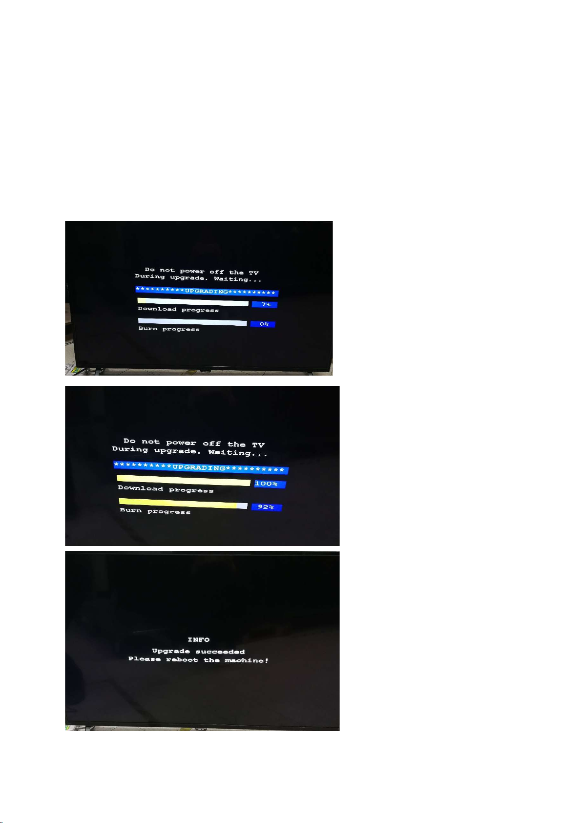
Step 2: F/W Upgrade
1. Power off then power on the TV. The TV will detect the USB memory stick automatically. Then a window jumps out as below:
2. When the TV software is updated, please reboot the TV. Remove your USB flash drive.
3. We can enter in CSM mode to check the current software version.
Caution: Please make sure that software upgrade is finished before unplug the USB and AC power!

Step 3: Check the SW version
1. After burning software, restart the TV.
2. Press “Option+123654”, enter Customer Service Mode to check if the software version is correct.

6. Circuit Descriptions
6.1 Introduction
The TPH17.2A LA is a new chassis launched in AP in 2017. The whole range is covered by V553 platform. The major deltas versus its predecessor
support DVB-C; DVB-T2, WIFI/multi-media, Video out.
The TPH17.2A LA chassis comes with the following stylings:
series xxPUD6172/xx
6.1.1 Implementation
Key components of this chassis are:
SCALER Hi3751ARQCV5530D00 LQFP216
AUDIO AD52580-QG28NAR (AF) 15W E-TSSOP
EMMC THGBMDG5D1LBAIT 4GB FBGA153
Silicon Tuner R842
6.1.2 Block diagram (For 715G9225)
 Loading...