

Page 1
Colour Television Chassis
KTM13.1
Contents Page Contents Page
1.Technical Specifications
2. The operation instructions
3.Mechanical Instructions
4.Trouble shooting procedure
5.TSUMV59XUS Scheme Adjustment of Factory Mode
6.TSUMV59XUS software upgrades (After Service)
7.TSUMV59 T9B block diagram
8.Main circuit diagram
9. The main board screen printing diagram
10.Power supply circuit diagram
Power supply printing diagram
Main IC and pins internal block diagram
key board circuit diagram
The IR board circuit diagram
Mechanical Overview
service training material list
Spare part list
key components list
1
3
24
30
36
38
52
53
57
62
63
66
69
70
71
72
73
75
2013-Aug-05
Page 2
1.Technical Spec
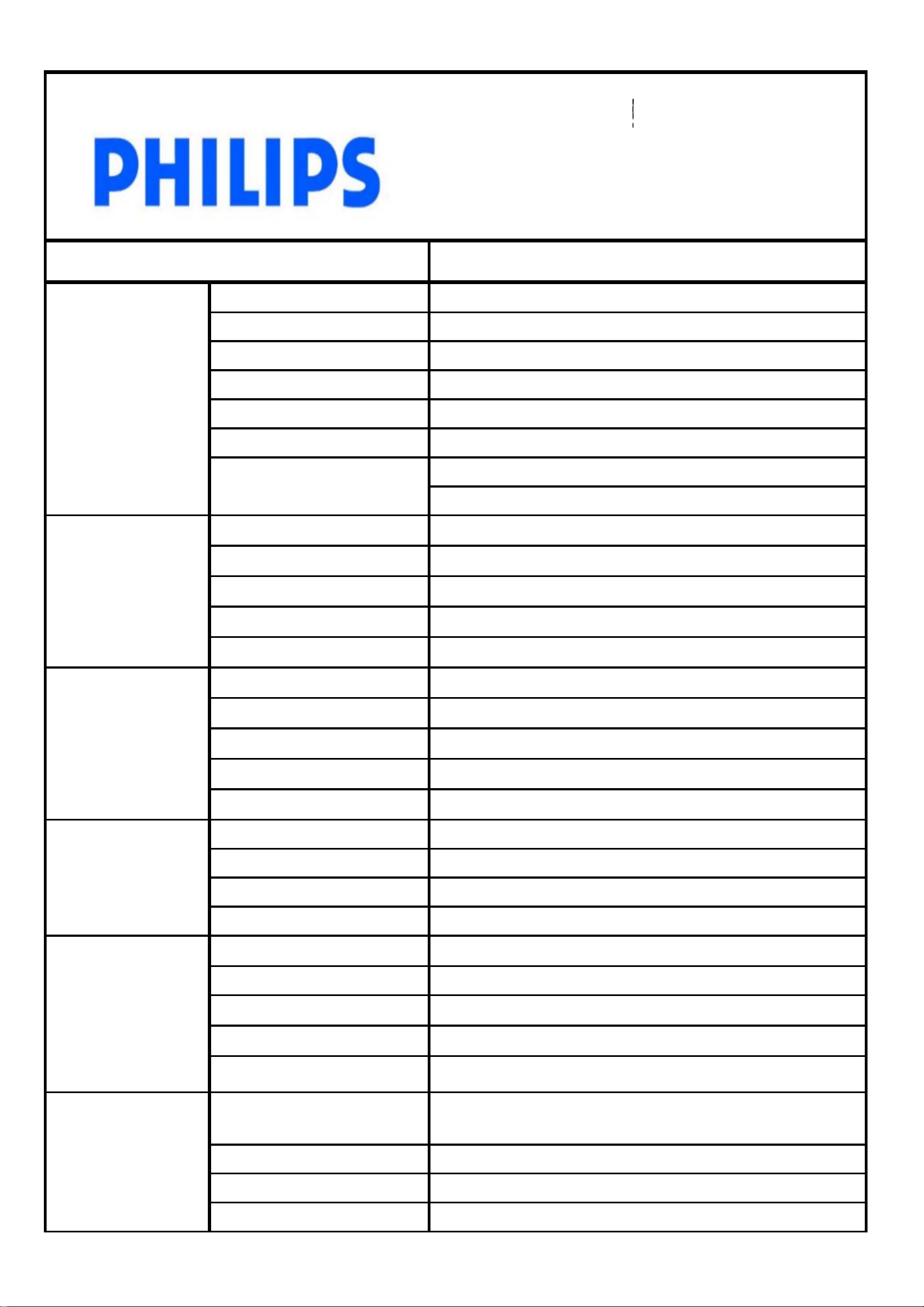
Technical Specifications
Panel
Description
Size and backlight
Resolution
Refresh Rate
Brightness
Dynamic Contrast Ratio
Response Time
Viewing Angle
ATV System
Sound system
50" FHD DLED Analog TV
50" DLED
FHD 1920×1080, Widescreen 16:9 Aspect Ratio
60Hz
330cd/m2 (Typ)
1000:1
8ms
Horizontal: 176 Degrees
Vertical: 176 Degrees
PAL+NTSC
I、D/K、B/G 、M
TV System
Signal Input
Audio Output
Nicam
Teletext
Digital Ampli fier
Composite + L/R Auido
Component + L/R Audio
HDMI
USB 2.0
PC Input
Buit-in Speakers
Headphone Output
Line Output
N/A
N/A
N/A
2
1
2
2
Analog RGB (Dsub) + 3.5Ø Audio Jack
8 Watts Total*2
1
1
Power
OSD Function
Digital Audio Output (S/PDIF)
Input range
Ambient Temperature
Consumption
Standby power consumption
Energy Efficiency Class
Languages
Picture Mode
Sound Mode
Sleep Timer
N/A
Universal 90~264 VAC 50/60Hz (Internal)
5 to 40 deg C
130Watts ( Max. )
≤0.5W
A
English(default), Arabic, Vietnamese, Thai, Indonesian,
Malaysia(Six languages
Vivid,Standard,Soft,Personal
Standard,Music,Cinema,Personal
Off ,10 to 180 Min (10 min per adjust)
)
1
Page 3
Description
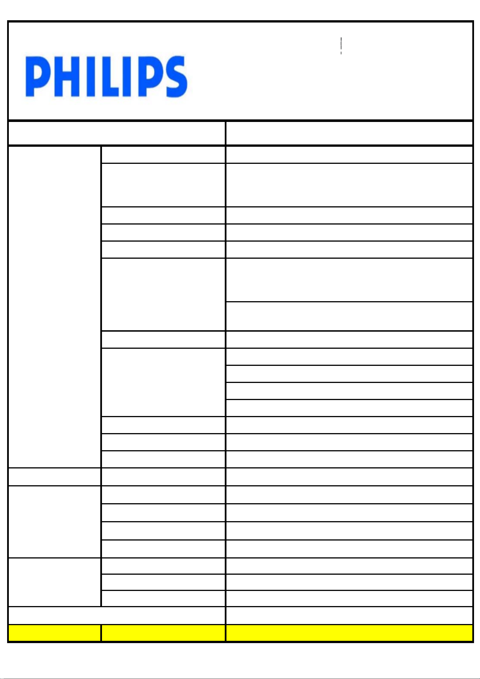
50" FHD DLED Analog TV
Features
Chipset
Picture Enhancement
Video playback
Music Support
Picture Support
Video support
TSUMV59MSXU
3D Comb Filter, 3D Color Management, Cross Color
Reduction,MPEG Noise Reduction, Montion Adaptive Deinterlacer
NTSC, PAL, SECAM
MP3
JPEG
Containers AVI, MKV, H264/MPEG-4 AVC, MPEG-1, MPEG-2,
MPEG-4, RealMedia (.rm, .rmvb, RV8-10), Motion JPEG
dat
、
、
M4A
BMP
、
mpg
AAC
(
、
mpeg1/2
、
)
PNG
H.264
、
、
vob
、
rm,
、
rmvb
、
mkv
、
div
、
avi
Regulations
Screen adjustment format
Sound Enhancement
Computer inputs
Video inputs
ID
asf
、
Widescreen, 4:3, Movie 16:9,Subtitle Zoom
Treble
Bass
AVL
Virtual Surround
up to 1920 x 1080 @ 60hz
24,25,30,50,60Hz up to 1920x1080p
Metal surface frame,super narrow bezel
CB
;
Unit w ith stand
Dimensions
(WxHxD)
Weight
Unit w ithout stand
Carton
Wall-mount
Product without Stand
Product with Stand
Product in Packaging
Loading Qty w/pallet
UPC Code
Note: Specifications are subject to change without notice. *Wall Mount Arm & Bracket not included.
UPC Code
1127×709×260mm
1127×650×71mm
1250×770×163mm
400*300 mm
15 kg
18 kg
21.5 kg
120(20") / 270(40") / 324(40"HIGH)
2
Page 4
2.The operation instructions
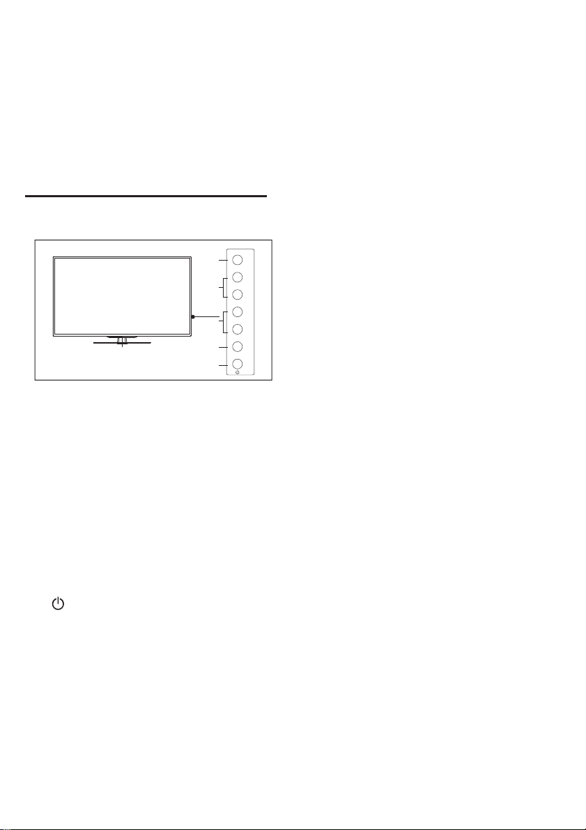
Control Panel
SOUR CE
2
CH+
-
CH
3
VOL+
-
VOL
4
MENU
1
1. Indicator/Remote Control
2. Source : display the list of signal
sources.
3. CH : switch to the
+/-
next channel.
4. VoL +/- : increase/reduce the
5. Menu : turn on/off the main
6. : turn on/off the TV; to cut off
power supply,please unplug the power
cable.
5
6
Sensor
previous/
volume.
menu.
3
Page 5
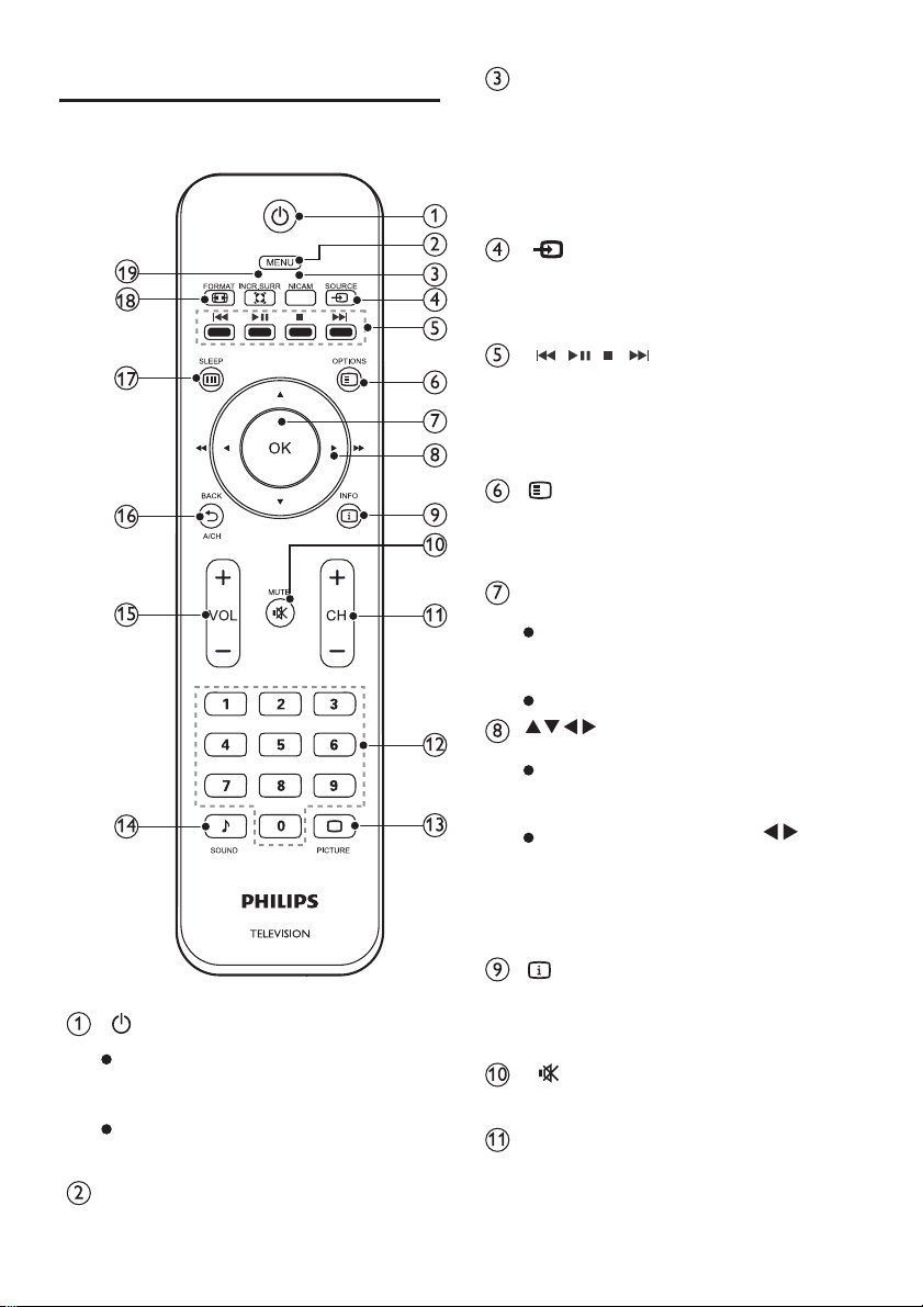
Remote Control
(Power/Standby button)
After power-up, press it to
turn on the TV;
Press it again to switch to
standby mode.
Menu
Turn on /off the menu.
NICAM
Switch between sound effects
(only available for TV signal
sources that support NICAM
function).
Source
Select an input source for the
TV.
Shortcut keys in USB mode:
pre vious, start/pause,stop,
next.
Options
Access the options related to
the current activity.
OK
In menu mode: confirm the
input or selection
In USB mode: play/pause.
In menu mode: navigate the
menu.
In USB mode: press to
search forward or backward
while playing music or video
files.
Info.
Display the program information
when available.
Mute
Mute or unmute the sound.
CH +/-
Switch to the previous/next
channel in TV mode.
Navigation keys
4
Page 6
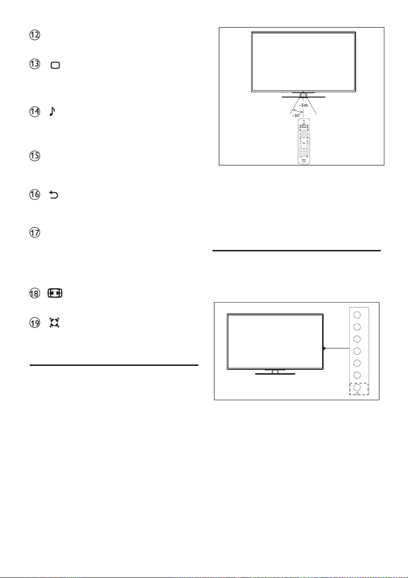
Numeric keys (0~9)
Select a channel or value.
Smart P
Switch to the preset image
mode.
Smart S
Switch to the preset audio
mode.
Volume +/-
Increase/reduce the volume.
Return / CH Switch
Return to the previous channel.
Sleep
Switch the TV to the standby
mode when the preset time is
out.
FORMAT
Select the aspect ratio of image.
Incredible Surround
Enable or disable the virtual
surround audio effect.
Use the Remote Control
When using the remote control,
please aim the remote control
transmitter at the remote sensor
on the TV. Make sure no
obstacles stay between the
remote control and TV.
4. Use the TV
The basic operations are described
in this section.
Switch
to Standby Mode
SOUR CE
CH+
CH
VOL+
VOL
MENU
-
-
5
Page 7
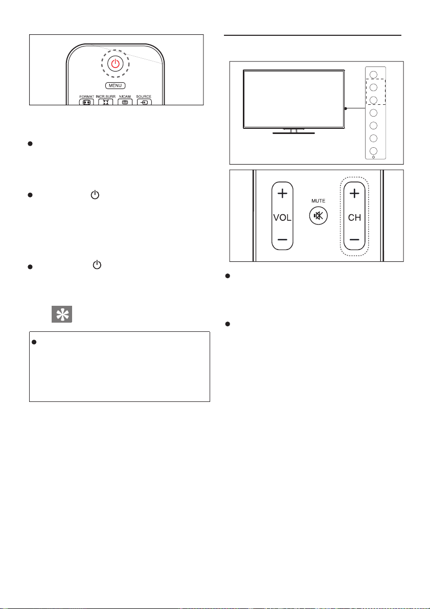
Switch the TV on
If the indicator is not lit, please
plug the power cord into the
power socket.
press the (Power/Standby)
key on the remote control or
the power key on the side
panel of the TV.
Switch TV to standby
Press the (Power/Standby)
key on the remote control.
Tips:
The TV still consumes a little power
in standby mode.If you will not use
the TV for long, please unplug the
Tv’s power
cord.
Switch the Channel
SOUR CE
CH+
-
CH
VOL+
-
VOL
MENU
Press the CH +/- key on the remote
control or key on the side
panel of the TV.
Choose a channel using the numeric
keys on the remote
CH +/
-
control.
6
Page 8
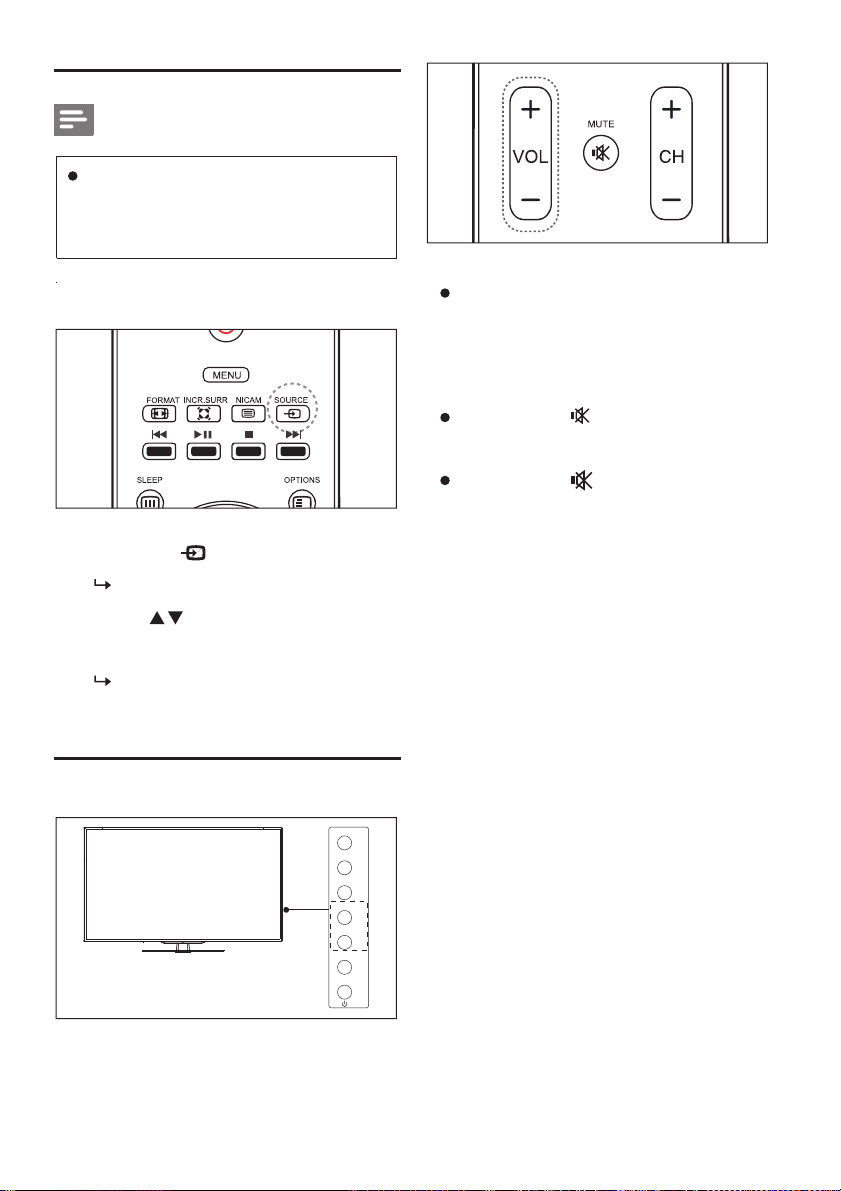
View Connected Devices
Note:
Please turn on the external device
connected to the TV before
selecting the signal source.
Use the Source Key
1. Press the key.
The list of signal sources
2. Press to choose a device.
3. Press the OK key to select it.
The TV is switched to the
selected signal source.
appears.
Increase or reduce the volume:
Press the Volume +/- key on the
side panel of the TV or on the
remote control.
Mute or unmute the sound:
Press the key to disable audio
output.
Press the key again to unmute
the sound output.
Adjust the Volume
SOUR CE
CH+
CH
VOL+
VOL
MENU
-
-
7
Page 9
5. Other Functions
Change the Language
Access the TV Menu
You can enter the menu to set up the
channel,change settings on image and
sound and access other
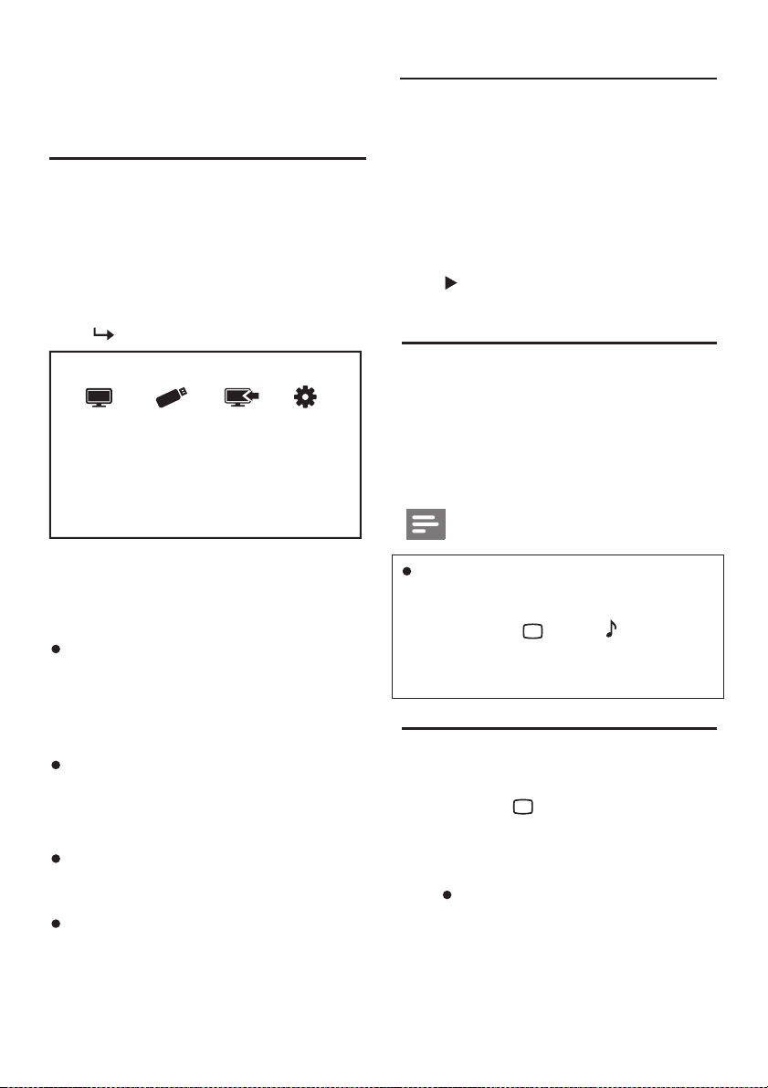
1. Press the Menu key.
The menu is displayed.
Watch TV Browse USB
2. Select the following options and
press the OK key:
[Watch TV ]: when other signal
sources are selected, you can
select this option to switch to the
TV program.
[Browse USB ]: view the photos
and play the music and video files
from the USB storage
[Device]: display the devices
connected to the TV.
[Setup]: change the image,
sound and other settings.
functions.
Device Setup
device.
You can change the menu language.
Change the menu language:
1. Press the Menu key.
2. Select [Setup] [Options]→
→
[Menu Language], and then press
to enter.
3. Select a language.
Change the Image and Sound
Settings
You can use the predefined image
and sound settings or change the
settings manually.
Note:
When watching the TV or a
connected device, you can
press the key or key to
enter the image and sound
settings directly.
Use the Smart P Mode
You can use the predefined image
1. Press the key.
2. Select one of the following options
and then press the OK
[Bright]:increase the
contrast and
definition.
settings.
key:
image
8
Page 10
[Standard]: adjust the
image settings to fit most
video sources and types.
[Soft ]: adjust the image
softness.
[User]: use the
defined image
user
settings.
Adjust the Image Settings
1. Press the Menu key.
2. Select [ Setup ] → [
Image
then press to enter.
3. Select one of the following
options and then press
to
enter:
[Smart Picture]: select the
predefined image settings.
[Contrast ]: adjust the
backlight and increase the
difference in backlight
intensity between the bright
area and dark area
[Brightness]: adjust the
light intensity and fineness
of the dark area (0~100).
[Saturation ]: adjust the
color saturation (0~100).
[Aspect Ratio]: adjust the
aspect ratio of the image.
-
Manually
],and
(0~100).
[ ]: Color Temperature
adjust the overall color
temperature of the image.
[Definition]: adjust the
image definition (0~100).
[Reduce Noise ]: filter and
reduce the noise in the
image.
[Tone]: adjust the color
balance of the image settings
(0~100).
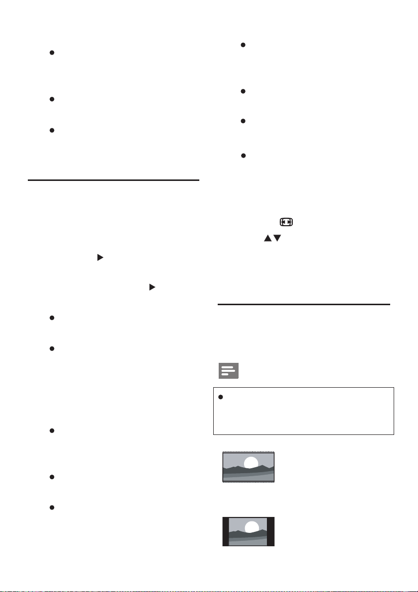
Change the Aspect Ratio
1. Press the key.
2. Press to select an image
format and then press the OK
key.
Aspect Ratio
You can select from the following
image formats.
Note:
Some of the image formats may
not be available for some signal
sources.
[Wide Screen]:
adjust the aspect
from standard to
screen.
ratio
wide
[4 3: ]: switch to the
standard aspect ratio
of 4:3.
-
9
Page 11
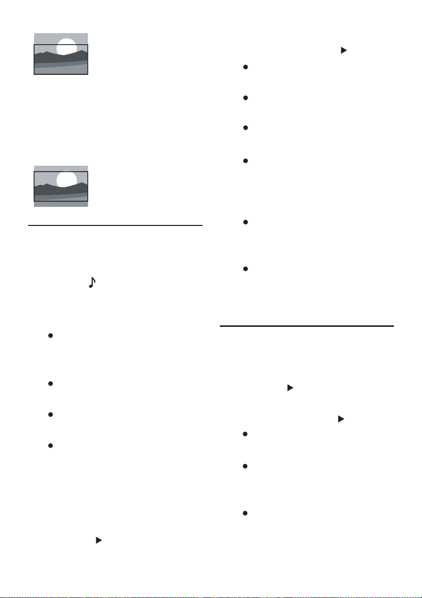
[Zoom in Subtitle ]:
display the image in
4:3 format, zoom in
the subtitles to fit the
width of the screen,
but part of the image
will be cut off on the
top.
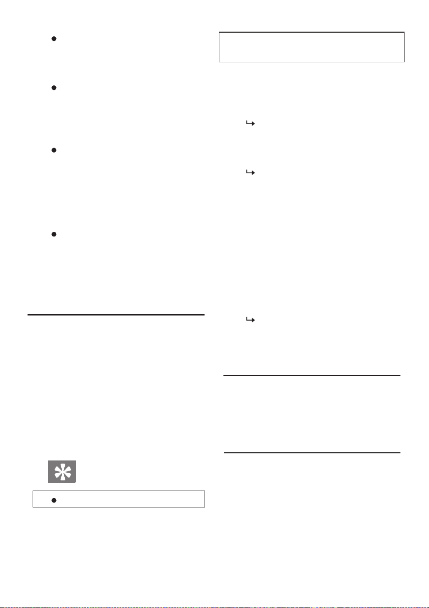
[16:9]: adjust the
aspect ratio from 4:3
to 16:9.
Use the Smart Sound
You can use the predefined sound
settings.
1. Press the key.
2. Select one of the following options
and then press the OK
key.
3. Select one of the following
options and then press
[Smart Sound]:select the
predefined sound settings.
[Bass]: adjust the bass
(0~100).
[Treble]: adjust the treble
(0~100).
[Auto Adjust]: suppress
sudden change in volume
when switching the
channel.
[Balance]: adjust the
balance between the left
speaker and right speaker.
[Virtual Surround]: enable
or disable the virtual
surround effect.
:
[Standard]: suitable for most
environments and signal
sources.
[Music]: suitable for music
files.
[Film]: suitable for video
files.
user
[User]: use the
sound
Adjust the Sound Settings
2. Select [ Setup ] [→ Sound],and
then press to enter.
settings.
1. Press the Menu key.
defined
-
Manually
Change the Other Settings
1. Press the Menu key.
2. Select [ Setup ]→[Options ],and
then press
3. Select one of the following
options and then press :
[Menu Language]: change
[Menu Timeout]: set the
[Menu Transparency]:
10
to enter.
to enter
the menu language.
time for displaying menu to
15s/30s/45s/60s.
change the menu transparency
(0~100).
Page 12
[ Blue Screen]: enable or
disable the blue screen display
function.
[Sleep Timer ]: set the time
period before the TV is
switched to standby mode
(0~180 min).
[Dynamic Backlight]: turn
on/off the dynamic backlight
(this optional function may
vary depending on the actual
products).
[ System Reset]: restore the
image and sound settings to
the factory default settings
(the channel settings wil notl
reset).
be
Use the Sleep Timer
You can switch the TV to the standby
mode after a preset amount of time.
Auto Switch to Standby Mo
Timer)
You can use the sleep timer to switch
the TV to the standby mode when the
preset time is out.
(Sleep
de
the preset time or reset the sleep
timer in the countdown process.
1. Press the Menu key.
2. Select [Setup] →[Options] →
[Sleep Timer ].
The sleep timer will be
displayed.
3. Select a preset time from 0~180
The preset time is available
in multiple of 10 minutes. If you
set it to 0 min”,the sleep timer ”
will be disabled.
4. You can also press the Sleep
key on the remote control to set
the sleep time.
Press the OK key to start the sleep
timer.
The TV will enter standby
mode when the preset time is
out.
Use the Lock Function
This function can prevent your child
watching certain programs or
channels.
min.
Tips:
You can turn off the TV before
Set or Change the Password
1. Press the Menu key.
2. Select [Setup]→[Child Lock].
3. Press the numeric keys on the
remote control to input your
password.
11
Page 13
Follow the instructions on
the screen to set or change your
password.
Tips:
If you’ve forgotten your password,
please input 3448" " to
After setting a new password, you
may need it when making some
settings.
Lock/Unlock Channels
1. Press the Menu key.
2. Select [Setup] [→ Child Lock]
→[Lock Channel ] and then nput
your password.
The channel list will be
3. Select the channel to be locked
or unlocked and then press the
OK key.
You are required to input the
password when you watch the
locked channel for the first time.
4. Exit the main menu, and the lock
settings will come into effect
immediately.
Note:
The child lock function works in
TV mode only.
overwrite it.
displayed.
Play USB Media
Video formats supported by USB:
Storage device: USB storage
(support FAT or FAT32 USB
storage devices only).
Multimedia files:
Photo file;
Audio file;
Video file.
Note:
Philips gives no guarantee to the
compatibility with USB
devices,and shall not be liable for
any data corruption or loss caused
by connecting
View Photos or Play Music and
Video Files from USB Storage
Device
1. Turn on the TV.
2. Insert the USB storage device to
the USB port on the side of the
TV.
3. Press the Menu key.
4. Select [ Browse USB ] and then press
the OK key.
Select the USB device you’ve inserted
and then press the OK
Enter the USB browser.
such device to theTV.
storage
key.
12
Page 14
View Photos
1. Select [ Photo ] on the USB
browser and then press the OK
key.
2. Select a photo or folder and
then press the OK key.The
photo will be auto played in full
screen.
View Photos as Slide Show
1. When a photo is played in full
screen, you can press the OK
key:
To view photos as slide show
starting from the current photo.
2. Use the follow keys to control the
slide show:
OK : play/pause.
: view the previous or
next photo.
: exit the slide show.
/
Change the Slide Show Settings
1. Press the key during
the
slide show.
2. Select one of the following
options and then press the
OK key:
[Start/Stop ]: start or stop
the slide show.
[Transition Effect]: set the
photo switch effects.
[Frequency ]: set the display
time of each photo.
[Random Play ]: select to
the photos in sequence or at
random.
[Play Once/Repeat]:
select to play the photos once
or repeat playing
them.
[Rotate]: rotate the photo.
[Capture]: set the photo as
the TV’s startup image or
reset the startup image.
[Details]: display the
information.
Listen to Music
1. Select [Music] on the USB
and then press the OK
2. Select a song or album and then
press the OK key to play it.
Change the Music Settings
Pr ess the key during the music
playing, select one of the following
options and then press the OK key.
[Start/Stop]:start or stop
[Play Once/Repeat]: select to
play the songs once or repeat
playing them.
13
play
detailed
browser
key.
playing.
Page 15
[Random Play]: select to play
the songs in sequence or at
random.
[Details]: display the detailed
information.
Play Music for Slide Show
You can play background music for
slide show.
1. Select a music album.
2. Press the OK key.
3. Press the key to return to the
USB browser.
4. Select a photo album.
5. Press the OK
show.
Watch Videos
1. Select [
browser and then press the OK
2. Select a video and then press
OK key to play it.
3. Use the following keys to control
the video playing:
OK: play/pause.
key to start the
] on the USB
Video
slide
the
key.
[Play Once / Repeat ]: select to
play the videos once or repeat
playing them.
[Random Play]: select to play
the videos in sequence or at
random.
[Aspect Ratio]: select the
format for video playing.
[Details]: display the
information.
Remove the USB Storage Device
Note:
Please follow the steps below to
remove the USB storage
it could be damaged.
1. Press the key to exit the
USB browser.
2. Remove the USB storage
about 5s later.
image
detailed
device, or
device
6. Set up the Channels
: search forward or
backward.
Change the Video Settings
Press the key during the video
playing,select one of the following
options and then press the OK key.
[Start/Stop]:start or stop
playing.
When you make TV settings for the
first time,you need to select a menu
language and search for TV
This Chapter will explain
and fine tune the
14
how to
channels.
channels.
search
Page 16
Auto Scan
Step 1: Select a menu language
1. Press the Menu key.
2. Select [Setup] [→ Options]→
3. Select your desired language.
Step 2: Channel
1. Press the Menu key.
2. Select [Setup
3. Press the OK
Manual Scan
Step 1: Select your TV system.
If your system has been set
1. Press the Menu key.
2. Select [Setup] [→ Channel].
3. Select your[Color System]and
Step 2: Search and save new
1. Press the Menu key .
2. Select [ Setup] [→ Channel] →
Language
[Me nu
to enter.
[Auto Scan ] and then press .
enter.
scan.
]and then
auto
scan
] [→
Channel ]→
key to start the
press
auto
Note:
correctly,you can skip this step.
[Sound System].
[Manual Scan].
channels.
to
Select [Channel] then and press
Select[Search ]and then press
3. When searching is finished:
[Select
channel as the current
Step 3: Fine tune the analog
1. Press the Menu key.
2. Select [Setup
[Fine Tune].
3. Press to adjust the channel
frequency.
4. Select [Done] to exit the fine
tuning.
to select a channel
to start channel scanning .
] save the to searched
Done
] [→
number.
channel.
Channel
channels.
]→
Channel Edit
1. Press the Menu key.
2. Select [ Setup ] [→ Channel]
→[Edit Channel].
3. Press to select a
and press to
[
Watch ], [Delete] or
channel
select
[Skip].
7. Connect Devices
You can connect devices with different
interfaces to this TV .
Note
You can connect the device to TV via
interfaces of different type.
15
Page 17
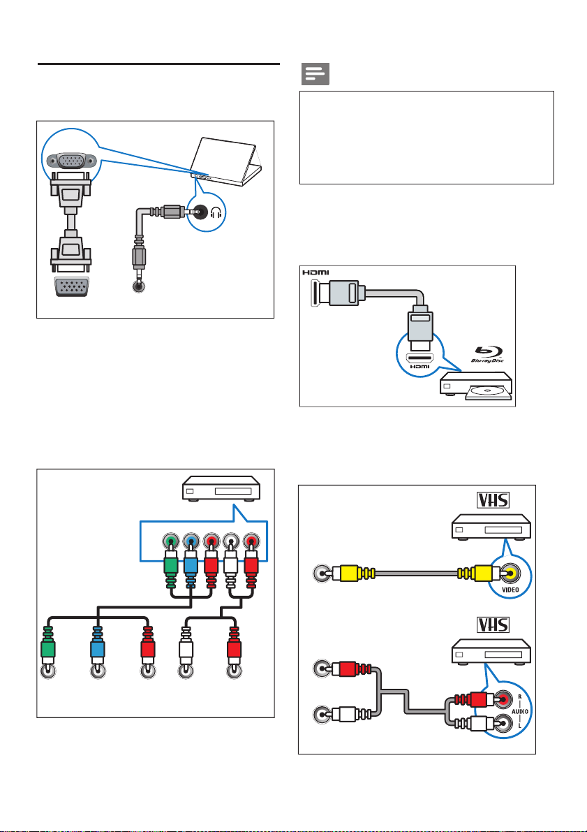
Interfaces on the back
① Audio & Video Input of PC
VGA
VGA
VGA IN
② Component Input/AV2 Input
(Video 2/Y Pb Pr Audio L/ Audio R)
You can connect to analog audio &
video input from analog/digital
like DVD players or game
Audio
devices
station.
Note
Video 2 shares the same input interface
with the component Y signal,and the
audio of the video 2 shares the same input
interface with the component
audio.
③
HDMI
Digital audio and video input of HD
digit al devices like a Blu-ray player
④
AV Input
Composite video input of analog
devices
like a VCR .
Pb
Y
Pb
Pr
AUDIO-L AUDIO-R
COMPONENT-IN
L RY
Pr
VIDEO
AV-IN
AUDIO-R
AUDIO-L
16
Page 18
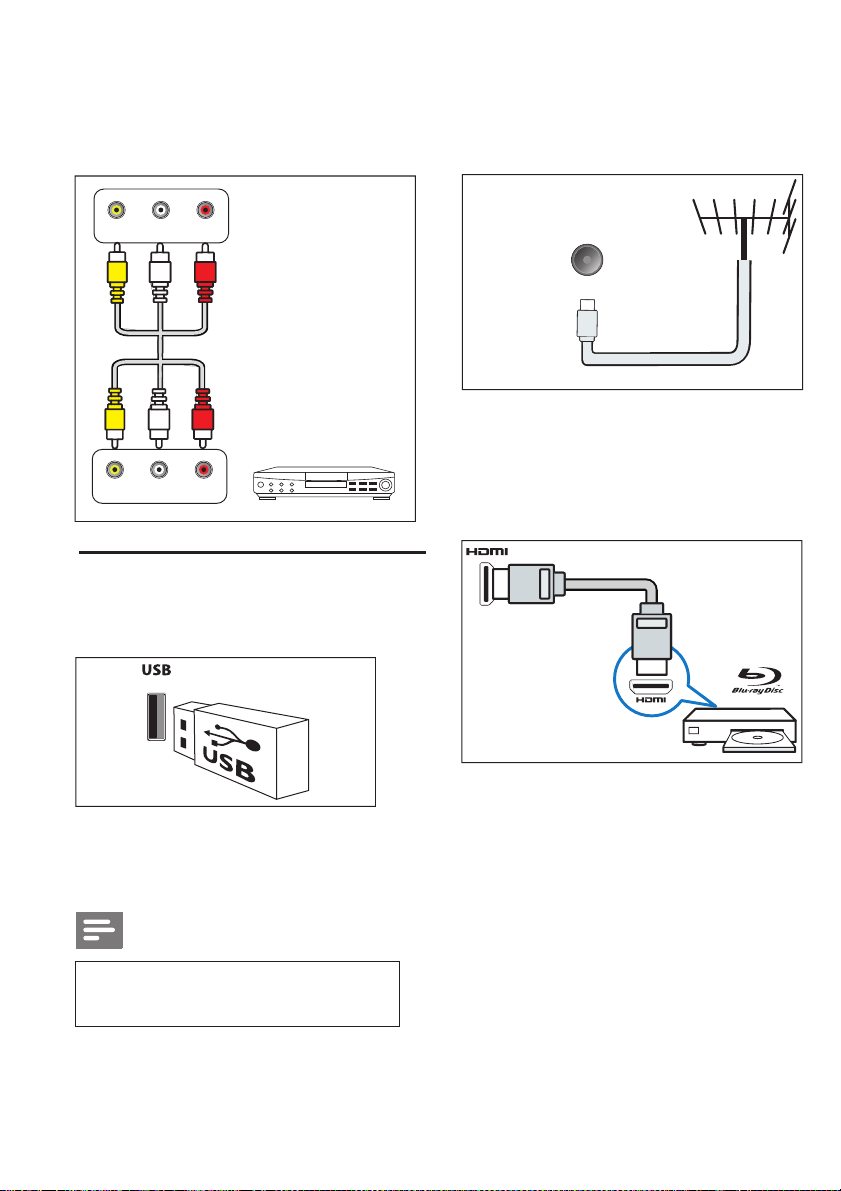
⑤
AV Out
Composite video output of analog
devices like a VCR.
Antenna/cable TV
③
Signal input from antenna,cable or
satellite.
VIDEO
VIDEO
AUDIO-RAUDIO-L
AUDIO-RAUDIO-L
AV Out
Connect to a device with
audio input
(such as
interface
a monitor)
Interface on the side
① USB
Connect to USB storage device.
Antenna
/cable
TV
HDMI
④
Digital audio and video input of HD
digital devices like a Blu-ray player
②
Headset
Stereo audio output to headset
Note
When you insert the headset,the TV
speakers will be muted
automatically.
17
Page 19
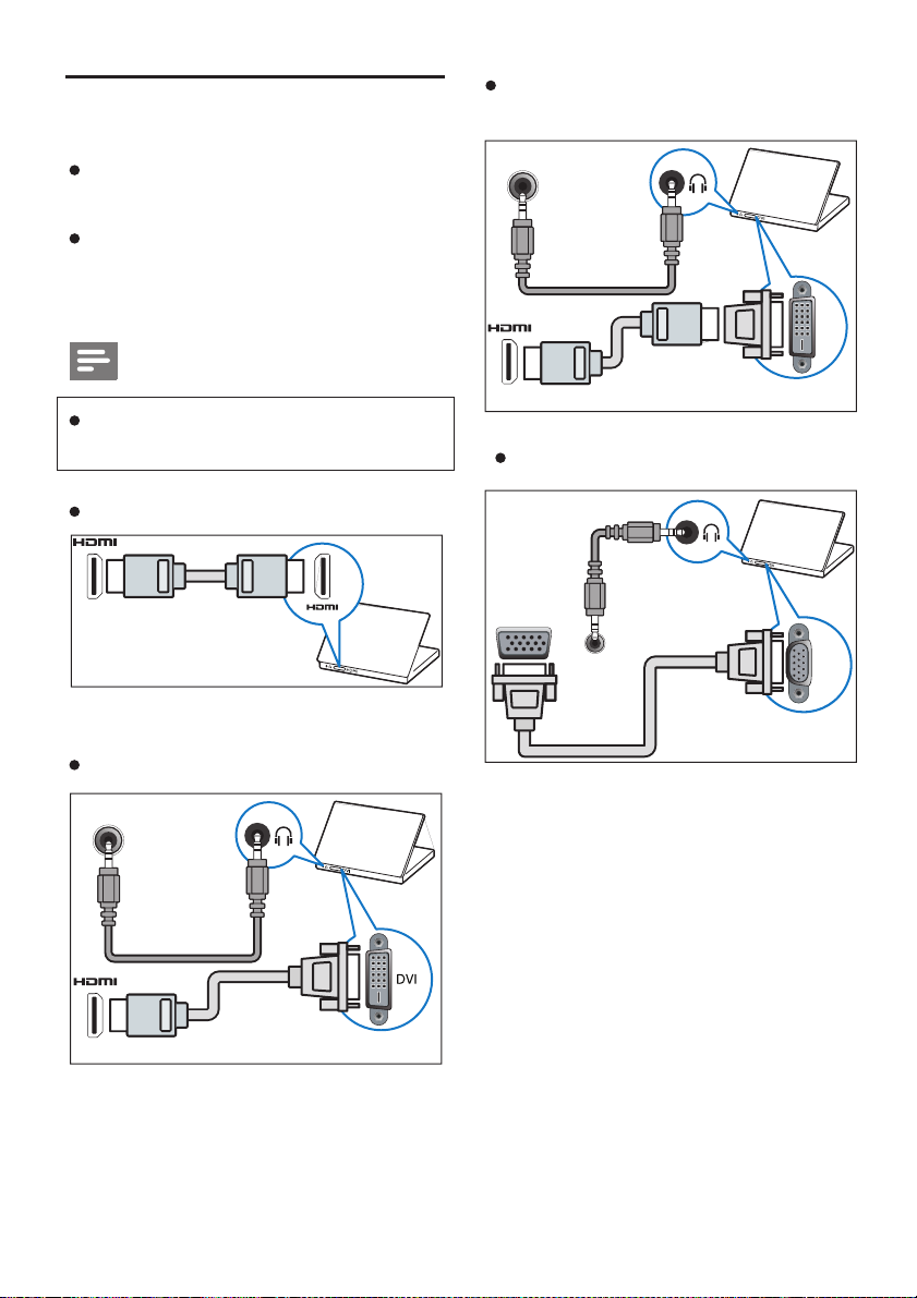
Connect to PC
Connect the TV to a PC.
Set the refresh rate to 60Hz on the
PC .
Select a supported resolution .
Connect to the PC via one of the
following interface s :
Note
HDMI Cable and HDMI-DVI
Adaptor
Audio
DVI
An extra audio cable is needed
when
connecting via DVI or VGA.
HDMI Cable
DVI-HDMI Cable
Audio
VGA Cable
VGA
Audio
VGA
18
Page 20
Use of Philips EasyLink
To obtain the best
suggested to use the Philips
EasyLink HDMI - CEC compatible
device s ,which can enhance the
control functions
compatible device connected via
HDMI interface can be controlled by
the TV remote control.
Philips EasyLink,you
Connect two or more HDMI-CEC
Make sure that each HDMI-CEC
Switch to EasyLink
The EasyLink compatible
source.
Philips gives no guarantee that the
all HDMI- CEC devices.
compatible devices via HDMI
interfaces
compatible device is working
normally.
Note
be enabled and selected as signal
interoperability can be realized
performance
.The HDMI
To enable
to:
need
,it is
CEC
-
device must
with
Note
If you don’t want to use Philips
please disable it.
1. Press the Menu key.
2. Select [Setting ] > [ EasyLink] >
[EasyLink]
3. Select [ON] or [OFF],and press
they OK key .
Use of Fast Play
When EasyLink is enabled,
Play on the device.
The TV will switch to the
correct signal source
Use of Fast Standby
Press (Power / Standby ) on
the remote control .
The TV and HDMI devices
connected will be switched to
standby mode .
EasyLink,
press
automaticall
y.
Enable or Disable EasyLink
When the HDMI-CEC compatible
device is enabled, the TV will be
started automatically and switch to
the correct signal source.
19
Page 21
8. Product Information
The product information is
subject to change without prior
notice. For detailed product
infor mation, please refer to
www.philips.com/support .
Display Resolution
PC Format
Resolution – Refresh Rate:
640 480 6× 0Hz
800 600 60Hz×
1024 768 60Hz×
1360 768 60Hz×
1600 900 60Hz×
1920 1080 60Hz×
Video Format
Resolution
480i -60Hz
480p -60Hz
576i -50Hz
576p -50Hz
720p -50Hz, 60Hz
1080i -50Hz, 60Hz
1080p -50Hz, 60Hz
-Refresh Rate:
Supported
Multimedia
Storage Devices Supporte d: USB
storage (only support FAT or FAT 32
USB storage devices.)
Multimedia Files Supported:
Image File
Audio File
Video File
Tuner/Receiver/Transmitter
Antenna Input: 75ohm coaxial
TV System: PAL, NTSC
Video Play:
PAL,NTSC,SECAM
Remote Control
Batt ery: 2×AAA
Power Supply
Main Power Supply:
100-240V~,50/60Hz
Standby Energy Consumption:
≤0.5W
Environment Temperature: 5- 40
Power Consumption :130W
(IEC75)
o
C
TV Mounting Bracket
Please purchase the Phillips TV
mounting bracket or equivalents
compatible with VESA standard
to install your TV.
20
Page 22
Keep a
TV of 2.2 inch (5.5cm) to prevent
minimum
damage to the cables and
clearance behind the
Warning
sockets.
9. Trouble Shooting
In case of trouble, before you
ask for services, please conduct
simple troubleshooting as below.
Please install the TV mounting
bracket according to the user
instructions supplied with it.
Koninklijke Philips Electronics
N.V shall not be liable for any
accident, personal injury or loss
caused by improper installation.
Screen
Size
(Inch)
50 400×300 4×M6
Dot pitch
(mm)
Mounting
Screw
Specification
The design and specification is
subject to change without prior
notice as the product will be
updated constantly.
Excluding TV base
Size ( W × H × D):
1127 × × (mm)650 71
Weight: 15.0kg
Including TV base
Size (W × H × D ):
1127 ×709 × (mm)260
Weight: 18.0kg
Common Troubles
Power - on failure:
Unplug the power cord from
the socket . Reconnect it after
one minute.
Check if the mains lead is
connected firmly.
Abnormal operation of remote
control:
Check if the battery electrodes
(+/-) in the remote control are
proper .
If the battery gets exhausted or
leaks,replace it.
Clean the remote control and
the TV sensor.
Standby indicator light flashes
Unplug the power cord from
the socket , and reconnect it
when the TV cools down.
trouble still exists, please
If this
contact with the Philips customer
service.
Forget the unlock password:
Select [Child Lock ]> [Change
Password], and input 3448 to
overwrite the current
password.
:
21
Page 23
Menu displayed in foreign
Set the menu to your desired
language.
When the TV is
switched to standby mode, it
makes squeak sound :
No operation is needed.This is
normal when the TV cools down
or gets preheating.
starting or
language :
Channel Troubles
Image Troubles
No image after powering on
the TV:
Check if the antenna has been
connected properly.
Check if a proper device is
selected as the signal source.
Sound Imagewithout :
Check if the image setting is
correct.
Poor signal receiving may be
caused by improper antenna
connection.
Check if the antenna has been
connected with the TV
The receiving quality may be
affected by loudspeakers,
audio device without
grounding, neon light ,high - rise
buildings,and other massive
properly.
objects.If possible,please try to
change the antenna direction or
keep the said devices away from
the TV to improve the receiving
quality.
In case of poor receiving quality
one channel,
in only
a fine tuning for
Poor image quality for devices
connected:
Check if the device is properly
connected.
Check if the image setting is
correct.
Image setting not saved:
Check if the TV setting has been
set to Home Mode . You can
change and save settings
in this mode.
Image Size does not fit the
Screen:
Try to use another aspect ratio
for image.
Improper image position:
The image signal from certain
devices may not fit the screen.
Please check the signal output
of the device.
this
Audio Troubles
Image without sound:
please make
channel.
flexibly
22
Page 24
Notice
If no audio signal can be detected,
the TV will disable the audio
automatically which doesn’t mean,
trouble.
Check if all cables are connected
properly.
Check if the volume is set to 0.
Check if the sound is muted.
Image with poor sound quality:
Check if the sound setting is
correct.
Only one speaker works:
Check if the
Sound Balance
to Middle.
HDMI Connection
Trouble in HDMI Devices:
Please notice that HDCP
support may cause delay to
display the content of HDMI
devices.
If the TV doesn’t identify the
HDMI device and display no
image,please try to switch the
signal source to another
and then switch back.
In case of intermittent sound,
please check if the output
setting of the HDMI device is
correct.
device,
output
set
is
If you use a HDMI - DVI adaptor
or a HDMI -DVI cable, please
check if the additional audio cable
has been connected to AUDIO
port (only for the
mini-jack).
Computer Connection
Unstable Display on TV
Check the resolution and
rate is supported by
refresh
your PC.
Set the TV image format to
Uncompressed.
Contact Us
If you cannot solve the troubles, please refer
www.philips.com/support for the
to
If it doesn’t help either, please contact
with your local Philips customer
center.
Warning
DO NOT try to maintain the TV
by yourself.It may result in serious
personal injury,
to the TV,
Notice
Before you contact the Philips
center, please take
model and
back
housing of the TV and
irretrievable damage
and void the
notes of your TV
serial number
warranty
printed on the
on
service
service
the pac
FAQs.
.
kage.
23
Page 25
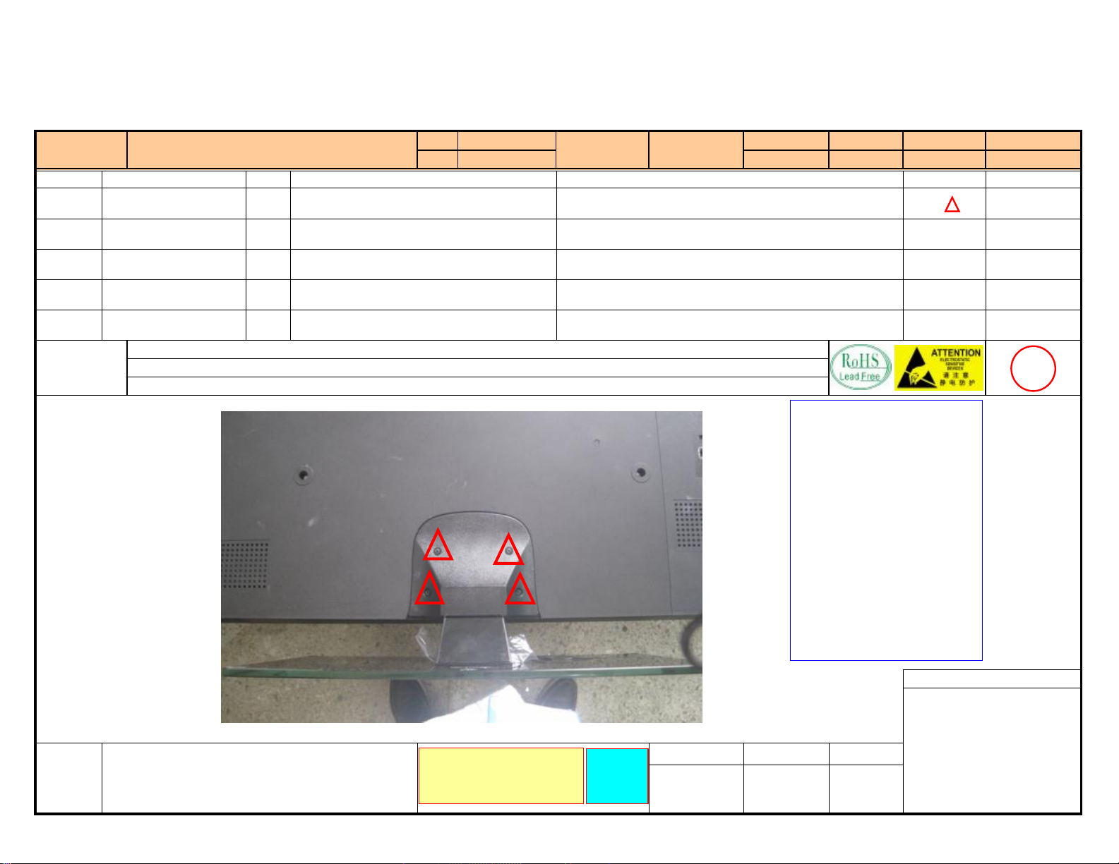
3.Mechanical Instructions
Station Name
NO
1 7B11-041593-00105111 4
2
3
4
5
Notice
Part Number
1. Wastes produced by this station shall be placed in the assigned position. Refer to Waste Classification and Disposal List .
2. Install screws by the serial number (install one by one) and abnormalities such as screws being neglected, tilted and slipped are not allowed.
Base Disassembling
Figure:
Model
Panel
Amount
Φ4×15mm B-head pointed-tail black-zinc-plated
tapping screws
Descriptions
50PFL3108/98
PHILIPS
Section/Serial No.
Unit Assembly 01
Document No. Version
Effective from
2012-2-25
Operations and Requirements
Take down the 4PCS screws with an electric screwdriver.
Take down the base and put it on specified place.
When finished, step on the switch with your foot to send the product to
next station.
Process Requirements:
1. Check for rusted screws, missing
slots or bad cross slot.
2. Check if the electric screwdriver
torque force is within the specified
requirements.
3.When installing screws, align the
electric screwdriver and the screw to
the screw hole vertically (do not tilt).
4. In the process of installing screws,
properly exert pressure to make a close
contact between electric screwdriver
and screw slot to avoid slipped screw.
5. Put the defective screws in the
defective product box and do not throw
them at will.
Date Updated
Diagram Tool Parameters
Electric screwdriver
7±1kgfcm
1
Recent
Modification
Record
Please read and understand the
operating instructions carefully
24
Take only
one screw
at a time
Project Controlled Seal
Prepared by Reviewed by Approved by
Page 26
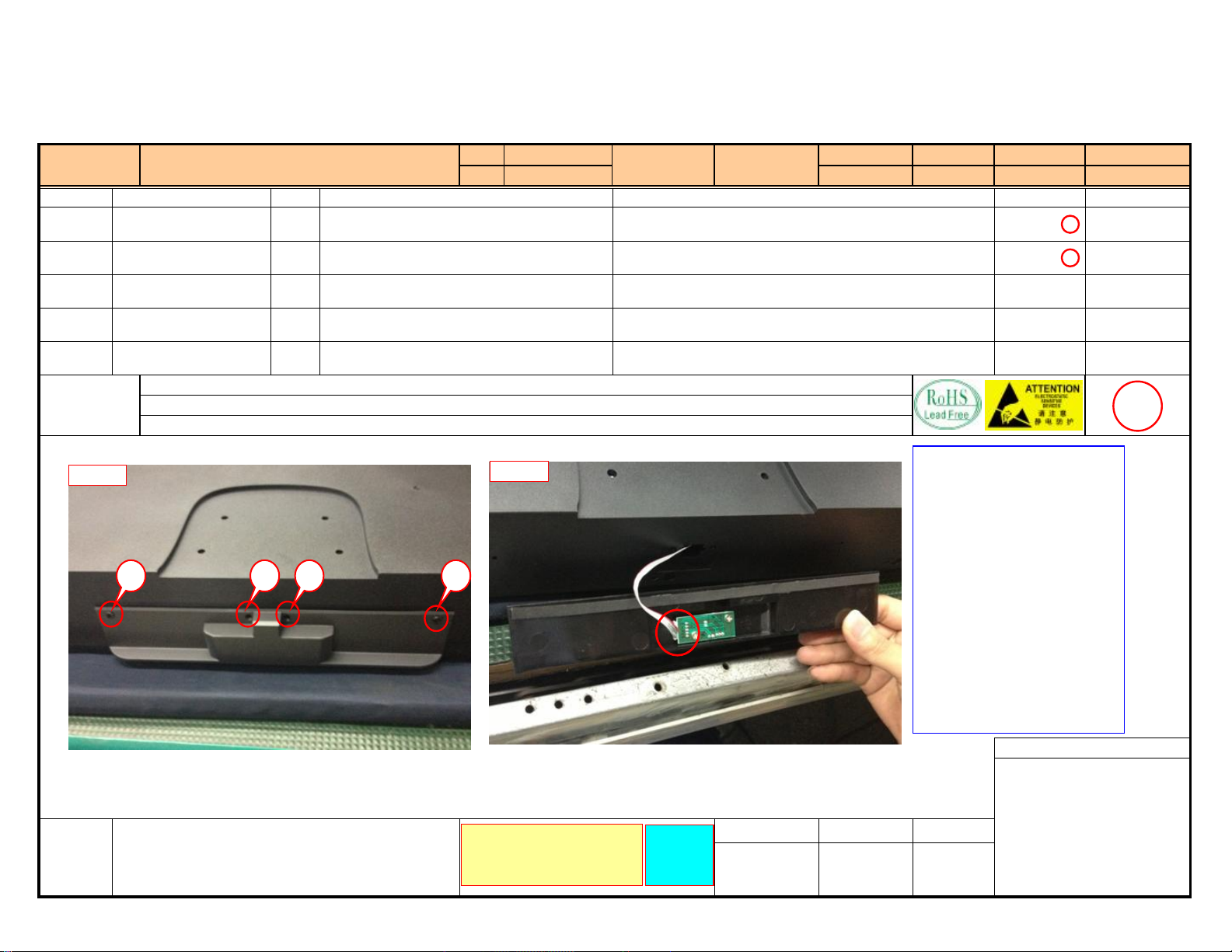
Model
Station Name
NO
1 7B11-030813-00105111 4 Figure 1
2 Figure 2
3
4
5
Notice
Back Cover Disassembling
Part Number Descriptions Operations and Requirements
1. Wastes produced by this station shall be placed in the assigned position. Refer to Waste Classification and Disposal List .
2. Install screws by the serial number (install one by one) and abnormalities such as screws being neglected, tilted and slipped are not allowed.
Amount
Ф3×8mm countersunk-head pointed-tail black-zincplated tapping screws
50PFL3108/98
Panel
PHILIPS
Section/Serial No.Unit Assembly 02
Take down the 4PCS screws with an electric screwdriver.
Pull out remote control receiver board wire and put it on specified
place.
When finished, step on the switch with your foot to send the product to
next station.
Document No. Version
Effective from Date Updated
Diagram Tool Parameters
Electric screwdriver
4±1kgfcm
2
Figure:
Figure 1
Recent
Modification
Record
Figure 2
1342
Please read and understand the
operating instructions carefully
Take only
one screw
at a time
Process Requirements:
1. Check for rusted screws, missing
slots or bad cross slot.
2. Check if the electric screwdriver
torque force is within the specified
requirements.
3.When installing screws, align the
electric screwdriver and the screw to
the screw hole vertically (do not tilt).
4. In the process of installing screws,
properly exert pressure to make a close
contact between electric screwdriver
and screw slot to avoid slipped screw.
5. Put the defective screws in the
defective product box and do not throw
them at will.
Project Controlled Seal
Prepared by Reviewed by Approved by
25
Page 27
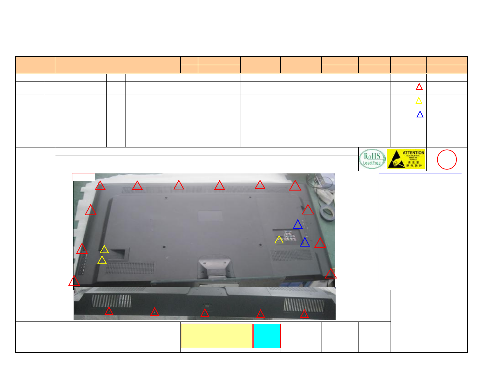
Model
Station Name
NO
1 7B11-031013-00105111 3 Figure 1
2 7B11-0306A6-00105111 17 Ф3×6mm flat-head black-zinc-plated machine screws Figure 1
3 7B11-030616-00105111 2 Figure 1
4
5
Notice
Back Cover Disassembling-A
Part Number Descriptions Operations and Requirements
1. Wastes produced by this station shall be placed in the assigned position. Refer to Waste Classification and Disposal List .
2. Install screws by the serial number (install one by one) and abnormalities such as screws being neglected, tilted and slipped are not allowed.
Amount
M3×10 countersunk-head pointed-tail black-zincplated tapping screws
Φ3×6mm countersunk-head black-zinc-plated machine
screws
50PFL3108/98
Panel
PHILIPS
Section/Serial No.Unit Assembly 03
Take down the 17PCS screws with an electric screwdriver.
Take down the 3PCS screws with an electric screwdriver.
Take down the 2PCS screws with an electric screwdriver.
Document No. Version
Effective from Date Updated
Diagram Tool Parameters
Electric screwdriver
4±1kgfcm
3
Figure:
Recent
Modification
Record
图一
Figure 1
Please read and understand the
operating instructions carefully
Take only
one screw
at a time
Process Requirements:
1. Check for rusted screws, missing
slots or bad cross slot.
2. Check if the electric screwdriver
torque force is within the specified
requirements.
3.When installing screws, align the
electric screwdriver and the screw to
the screw hole vertically (do not tilt).
4. In the process of installing screws,
properly exert pressure to make a close
contact between electric screwdriver
and screw slot to avoid slipped screw.
5. Put the defective screws in the
defective product box and do not
throw them at will.
Project Controlled Seal
Prepared by Reviewed by Approved by
26
Page 28
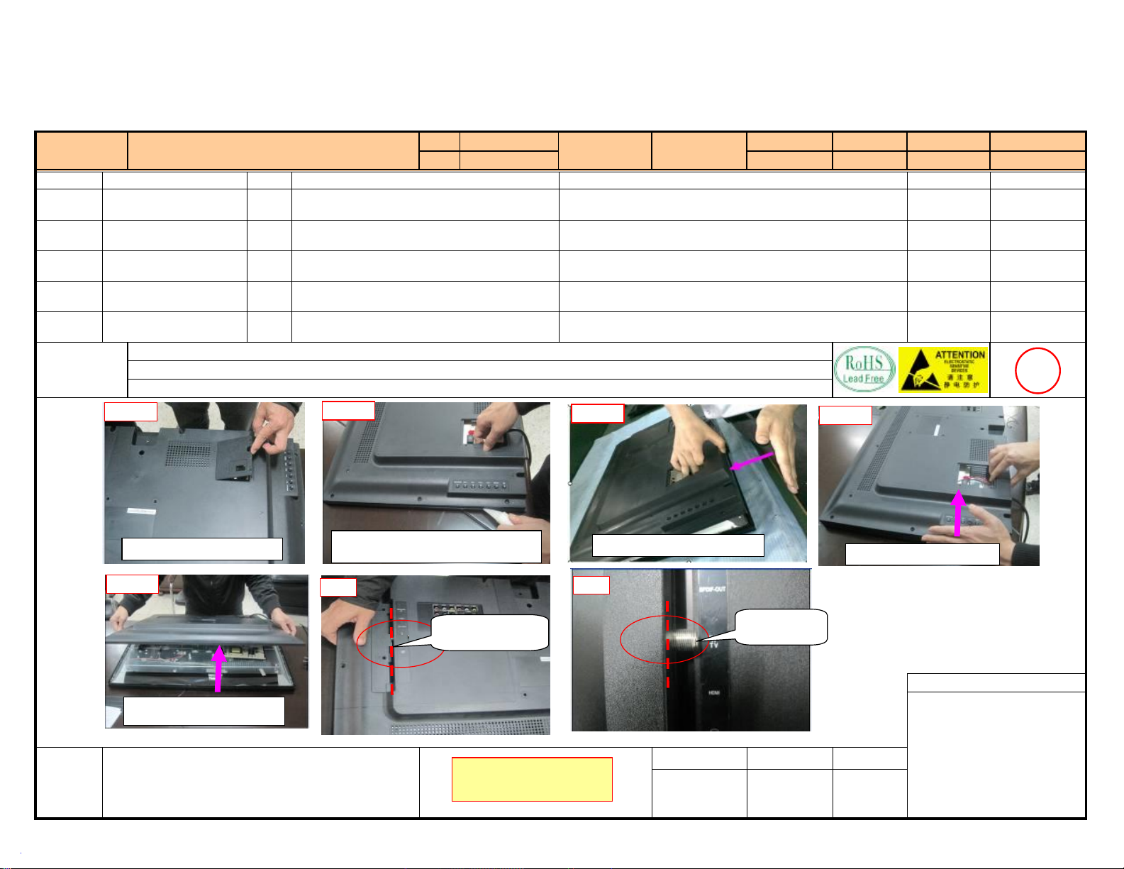
Station Name
图一
NO
1
2
Model
Back Cover Disassembling-B
Part Number Descriptions Operations and Requirements
Amount
50PFL3108/98
Panel
PHILIPS
Section/Serial No.Unit Assembly 04
Take down power cord cover, then disassembly back cover from lower
left corner of machine.
Slap lower left side of back cover.
Document No. Version
Effective from Date Updated
Diagram Tool Parameters
3
4
5
Notice
Figure:
Slap left side of back cover.
Open the back cover from top side of machine, do not touch LNB.
1. Wastes produced by this station shall be placed in the assigned position. Refer to Waste Classification and Disposal List .
Figure 1
Take down power cord cover
Figure 5
Figure 2
Disassembly back cover from lower left
corner of machine.
OK
LNB does not exceed
the dotted line
Figure 3
Slap lower left side of back cover.
NG
4
Figure 4
Slap left side of back cover.
LNB exceed the
dotted line
Open the back cover from top
side of machine
Recent
Modification
Record
Please read and understand the
operating instructions carefully
27
Project Controlled Seal
Prepared by Reviewed by Approved by
Page 29
50PFL3108/98
Station Name
NO
1 Figure 1
Back Cover Disassembling-C
Part Number Descriptions Operations and Requirements
Amount
Model
Panel
PHILIPS
Section/Serial No.Unit Assembly 05
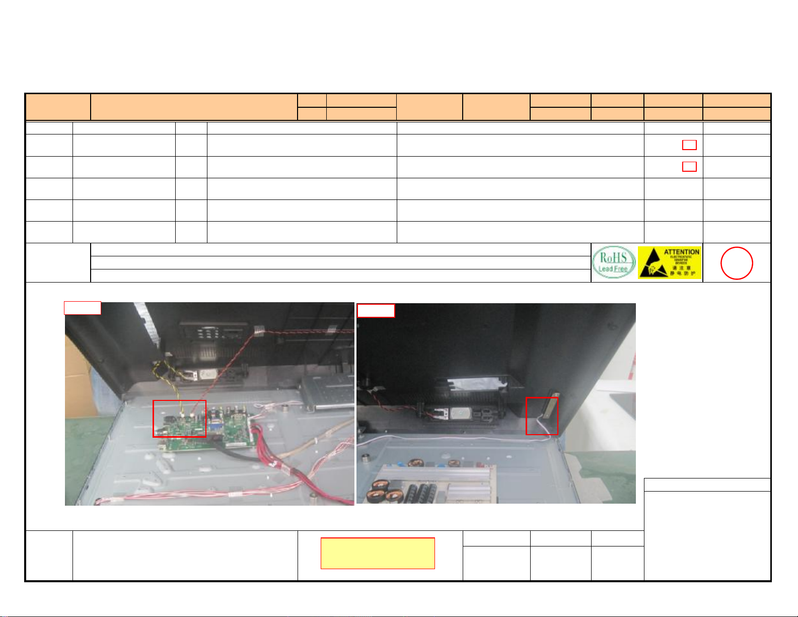
Pull out red/black and yellow/black speaker wires.
Document No. Version
Effective from Date Updated
Diagram Tool Parameters
2 Figure 2
3
4
5
1. Wastes produced by this station shall be placed in the assigned position. Refer to Waste Classification and Disposal List .
Pull out key board wire.
Take power cord and pass through power cord hole on back cover.
When finished, step on the switch with your foot to send the product to
next station.
Notice
Figure:
Figure 1
Figure 2
5
Recent
Modification
Record
Project Controlled Seal
Prepared by Reviewed by Approved by
Please read and understand the
operating instructions carefully
28
Page 30
50PFL3108/98
Station Name
NO
1 7B11-0307C2-50102111 4 Figure 1
2 7B11-030696-00101111 1 Φ3×6mm B-head nickel-plated machine screws Figure 2
3
4
5
Notice
Mainboard Disassembling
Part Number Descriptions Operations and Requirements
1. Wastes produced by this station shall be placed in the assigned position. Refer to Waste Classification and Disposal List .
2. Install screws by the serial number (install one by one) and abnormalities such as screws being neglected, tilted and slipped are not allowed.
Amount
M3×7mm P-head white-zinc-plated machine screws
with spring and flat washers
Model
Panel
PHILIPS
Section/Serial No.Unit Assembly 06
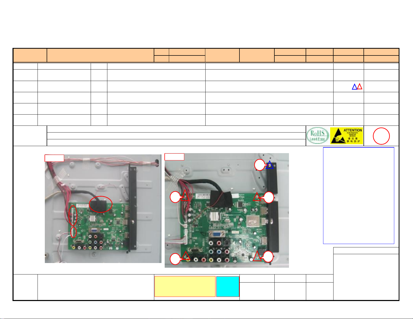
Pull out all wires on mainboard.
Take down the 5PCS screws with an electric screwdriver, then take
down I/O baffle plate and mainboard.
Arrange the wire properly.
Document No. Version
Effective from Date Updated
Diagram Tool Parameters
Electric screwdriver
5±1kgfcm
6
Figure:
Recent
Modification
Record
Figure 1
Figure 2
1
4
Please read and understand the
operating instructions carefully
Take only
one screw
at a time
Process Requirements:
1. Check for rusted screws, missing
5
3
slots or bad cross slot.
2. Check if the electric screwdriver
torque force is within the specified
requirements.
3.When installing screws, align the
electric screwdriver and the screw to
the screw hole vertically (do not tilt).
4. In the process of installing screws,
properly exert pressure to make a close
contact between electric screwdriver
and screw slot to avoid slipped screw.
5. Put the defective screws in the
defective product box and do not
throw them at will.
2
Prepared by Reviewed by Approved by
Project Controlled Seal
29
Page 31
Document:After- salesMaintenanceS erviceManualNo.:T7**
Version:
3.0E ffectivefrom:March15th,2010
Pageof14K TC
KTC
KTC
KTC
1
After-salesMaintenanceServiceManual
Date:March
2010
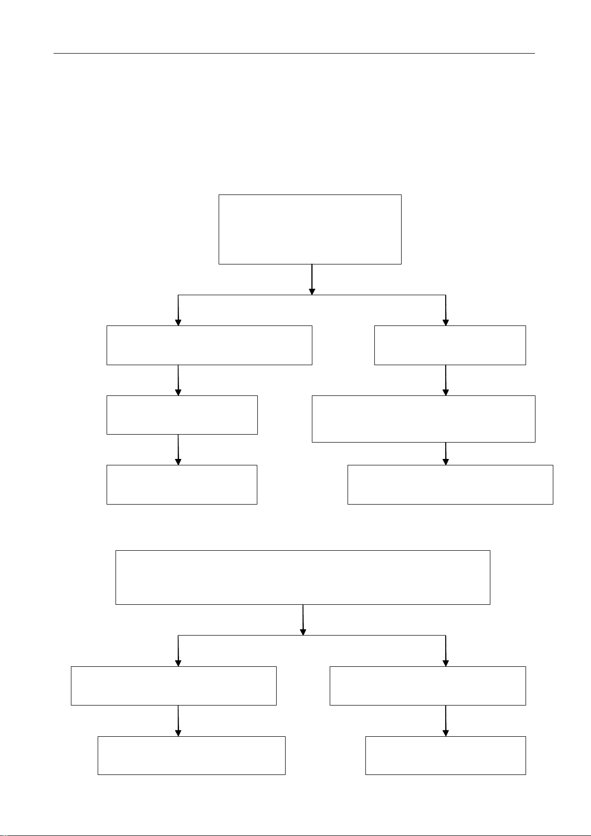
Troubleshooting
Troubleshooting
TroubleshootingProcedure
Troubleshooting
4.
1.
No
1.
1.
1.No
power
No
power
Nopower
power
YESNO
Procedure
Procedure
Procedure
Check220Vpowersupplyvoltage
andthecontactofpowersocket
CheckAC(220V)voltageandthe
contactofCN101socket.
Check+5Vand+12Voutputfrom
embeddedpowersupplyforabnormity
YESNO
Check+5Vand+12Von
mainboardforabnormity
YES
Checkforopen-loopoffuse,
orreplacemainboard
2.
Without
2.
Without
2.
2.Without
Withoutlight
light
light
light
Whentheindicatorisonbutthereisnodisplay,checkremotecontrolfor
power-off,minimumbrightness,contrastratio,checkhigh-voltageswitchboard
controlledbymainboardforabnormity
Replacepowercordorpower
socket
Abnormaloutputvoltage+5Vand+12Vfrom
embeddedpowersupply,replaceembedded
powersupplywiththesamemodel
NO
Checkmainboardofpowersupplyfor
looseness,open-loopandpoorcontact
YES
Checkthefuseonhigh-voltageboardfor
thesupplyof12V
YES
Replacehigh-voltageswitchboardCheckfuse
30
Checkeachtriodeofcontrolpartfor
abnormityorreplacemainboard
NO
NO
Page 32
3.
Protection
3.
Protection
3.
3.Protection
Protectionor
after
after
after
afterthe
or
without
or
without
orwithout
withoutlight
the
emergence
the
emergence
theemergence
emergenceof
light
(refers
light
(refers
light(refers
(refersto
of
image)
of
image)
ofimage)
image)
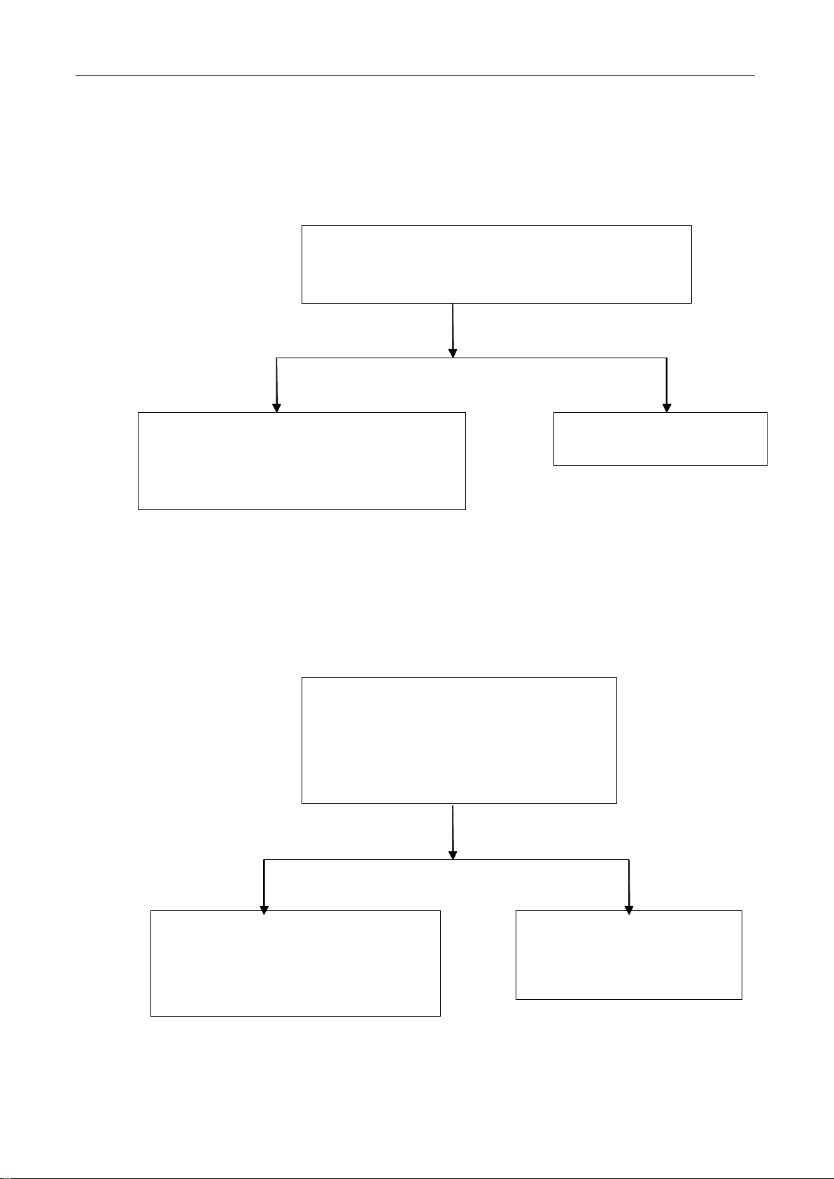
Theimagedisappearedimmediatelyafterthe
emergence;checktheplugofhigh-voltageswitchboard
forstrikingsparksandpoorcontact
to
the
to
tothe
disappearance
the
disappearance
thedisappearance
disappearanceof
of
image
of
image
ofimage
imageseveral
several
several
severalseconds
YES NO
seconds
seconds
seconds
Noproblemsidentified,replacehigh-voltage
board;ifthefaultremains,checkthecontact
lineofbacklightofLCDforanydamage,and
replaceLCDboard.
4.
White
4.
White
4.
4.White
Whitepanel
panel
panel
panel
Whitepanelreferstothebacklightworks
withoutvisiblesignalandjustshowwhite
screen.Checkthevoltageofsocketforflat
cableconnectingthemainboardtoscreen
forabnormality
Ifthereissparkstriking,
replacehigh-voltageboard
YESNO
Checktheinterfacebetweenmainboard
andconnectlineforanylooseness,
shedding,ifnoabnormityexisted,
replaceLCDscreen
Checkthepowersupplychipof
controlscreenorreplacemain
board
31
Page 33
5.
White
5.
White
5.
5.White
Whitescreen
no
no
no
nosignal
screen
screen
screenafter
signal
signal
signalinput,
YESNO
after
power
after
power
afterpower
power-
input,
input,
input,the
Checkwhetherthereischangeofvoltageatthehighvoltage
boardcontrolledbymainboardwhenpower-onandpower-off
the
the
thescreen
-
off
-
off
-off
off(work
screen
screen
screenshows
shows
shows
showsa
(work
(work
(worknormally
normally
normally
normallywhen
a
white
a
awhite
screen)
white
whitescreen)
screen)
screen)
when
when
whenpower
power
power
poweron,
on,
on,
on,but
but
when
but
when
butwhen
whenpower
power
power
power-
-
-
-off
off
or
off
or
offor
or
Checkwhetherthevoltagechangeofthecontrolpinson
thepluginterfaceofhighvoltageboardisnormalwhen
power-onandpower-off
Thecircuit
relatedto
highvoltage
boardispoor
6.
TV
6.
6.
6.TV
without
TV
without
TVwithout
withoutchannel
Checkwhetherthelines
betweenmainboardandhigh
voltageboardisinopen-loop
orpoorcontact
channel
channel
channelor
or
with
color
or
with
orwith
withcolor
CheckTVantennaplugforloosenessand
poorcontact
cast
color
cast
colorcast
cast
Checkwhetherthevoltageofthepinonmain
controllingtheworkingvoltageofhighvoltageboardis
normalwhenpower-onandpower-off
YES YESNO NO
Checkrelevantcircuitsof
highvoltageboard
controlledbymainboard
Replacepoormain
chipsorrecopy
software
chip
Ifwithcolorcast,checkthesettingof
colorsystemundermenu;andchange
ofcolorsystemtoseewhetheritis
normal(Usuallysettoautomatic)
NO
Checktheantennaanditssignal
source,ifnoproblemsexist,replace
tunerorcontrolchipswiththesame
model
YES
Replaceantennaplug
32
Page 34
7.
7.
7.
7.Poor
Poor
sound
Poor
sound
Poorsound
sound
Poorsoundreferstowithoutsoundorwithnoise;check
whethertheselectionofsoundsystemisproper
YES
Switchtootheraudioinput,checkwhetherDVD
inputandPCmainboardinputhassound
NO
Nosoundforotherinputs;checkthesound
amplifierandthesharedcontrolcircuitThereissoundforotherinputs,
8.
No
VGA
8.
8.
8.No
No
VGA
NoVGA
VGAinput
input
signal
input
inputsignal
signal
signal
VGAsignalinputdoesnotrespond,thescreen
prompts“Pleaseinputsignal”,checkwhetherPC
signalsourceandsignallineisnormal.
NO
Nosound;checkwhetherremotecontrolmuteis
selectedandswitchsoundsystem
YES
replaceTVtunerorcontrolchip
CheckVGAsignalinputboardandseewhethertherow
andfieldsyncsignalprotectiondiodeisbrokedown
NO
Replacethemotherboardor
factoryresetisnormalReplacethe5.6VZenerdiode
NO YES
ReplacePCorsignalline,check
displayVGAplugforlooseness
YES
onthemotherboard
33
Page 35
9.
Poor
9.
Poor
9.
9.Poor
Poorembedded
embedded
embedded
embeddedpower
power
power
powersupply
Poweron,checkembeddedpowersupply5VSBinTVfor5Vvoltageoutput
supply
supply
supplyof
of
of
ofTV
TV
TV
TV
YES
Highelectricallevelexistedat
STB(higherthan2.5V)
YESNO
Check+5V,+12V
fornormalinput
NO
Replacepowersupply
Checkpowersupplylineforlooseness,checkindictorfor
workingandpowersupplysocketforlooseness
CheckEC2for380-400V
voltage;ifthereisnot,
replacepowersupply
YES
Fastenlines
andsocket
NO
NO
Replacepower
supply
10.
Common
10.
Common
10.
10.Common
Commonfault
fault
fault
faultof
of
LCD
of
LCD
ofLCD
LCDscreen
screen
screen
screen
10.1Brightlineorbrightbelt(BL):constantlongitudinalortransverseilluminatinglineor
beltduetonon-conformedconnectionbetweenICandglass
10.2Darkline(DL):constantlongitudinalortransverseilluminatinglinedueto
non-conformedconnectionbetweenICandglass.
10.3Whitepanel(WP):onlylighttubeilluminatesowingtonon-conformeddriveplateof
theLCD,withoutanydisplaysignalinthedisplayarea,andthewholescreeniswhite.
10.4Screenbreaking:(overflowofLCD):withdamageorinvisibledamageoftheliquid
crystalglass,irregularblackdefectoccursfromliquidcrystalbodytoglassandpolarizer,
whichcannotbeseenatanyimage.Theoverflowportioncannotformimageanddoesnot
display.
10.5PressingScrape(PS):afterlocaldisplayareaatthefrontofLCDisheavilypressed,
34
Page 36

glassofthepressedportionisnotdamaged,theliquidcrystalbodycannotdisplaynormally,
withspotorblockblackdefect.
10.6Screenmess:irregularcolordisplayarisingfromdamageofdrivingplateinLCD.
35
Page 37
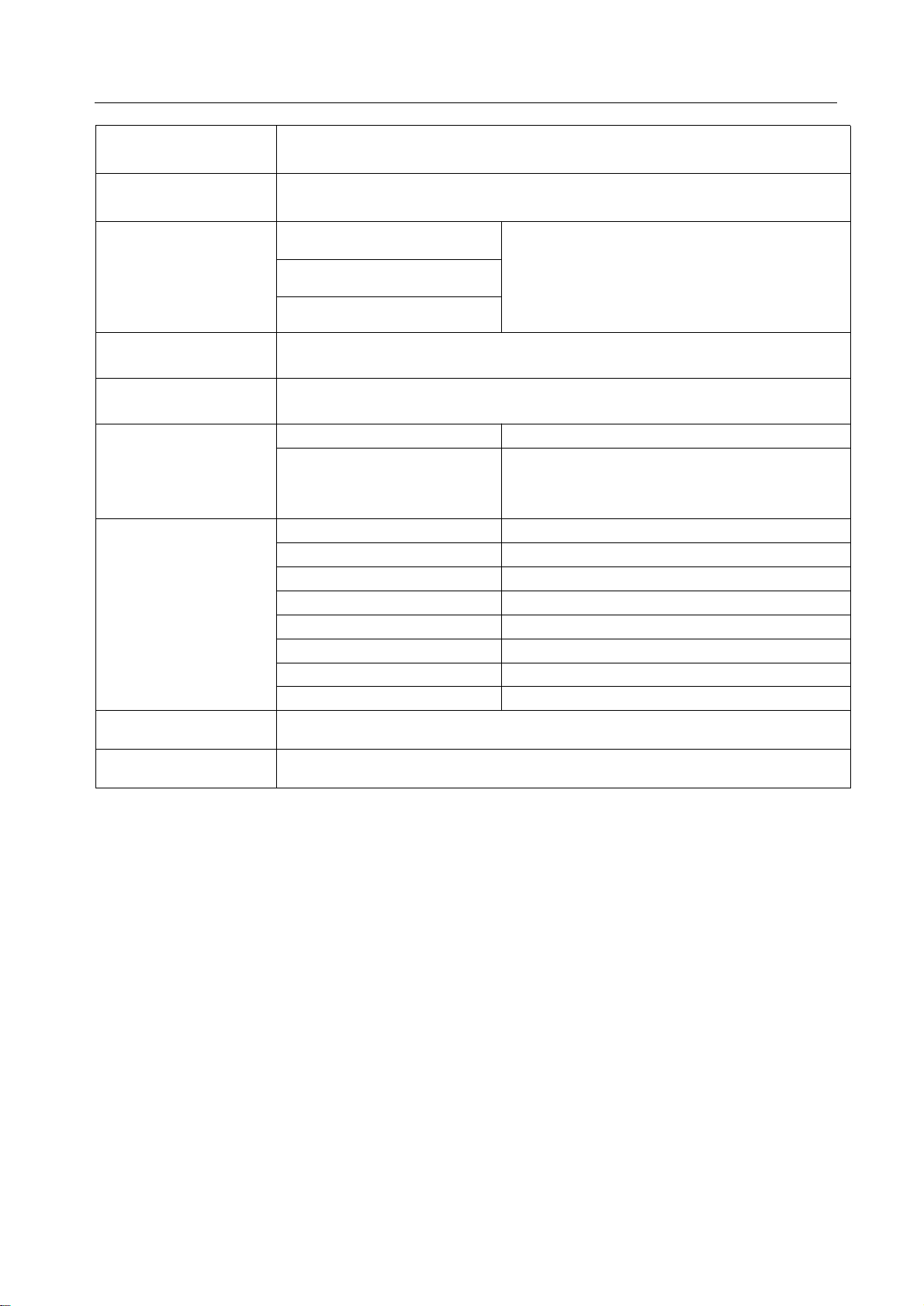
Scheme
Scheme
Scheme
TSUMV59XUS
PressMenutoenterintothemenuinterface,andthenpress8202toenterintoFactorymenu.
SchemeAdjustment
Adjustment
Adjustment
Adjustmentof
of
Factory
of
Factory
ofFactory
FactoryMode
Mode
Mode
Mode
Primary
Primary
Primary
PrimaryMenu
ADCADJUST
PICTURE
MODE
W/BADJUST
SSCADJUST
Menu
Menu
Menu
Secondary
Secondary
Secondary
SecondaryMenu
MODEVGA(RGB),YPbPr(SD,HD)selection
R-GAIN
G-GAIN
B-GAIN
R-OFFSET
G-OFFSET
B-OFFSET
AUTOADC
MODE
PICTUREMODE
BRIGHTNESS
CONTRAST
COLOR
SHARPNESS
TINT
MODE
TEMPERATURECool,Standard,Warm
R-GAIN
G-GAIN
B-GAIN
R-OFFSET
G-OFFSET
B-OFFSET
MIUEnable
MIUSpan
MIUStep
LVDSEnable
LVDSSpan
LVDSStep
Menu
Menu
Menu
Value,
Value,
Value,
Value,Notes
ADCADJUST
Front-endgainadjustment
Clampleveladjustment
AutomaticADCadjustment
Picturemode
Signalsourceselection
Modes:dynamic,standard,soft,user.
Colorsaturation
Colortemperatureadjustment
Signalsource
Whiteleveladjustment
Blackleveladjustment
Spreadspectrumadjustment
MIUspreadspectrumEnable
spreadspectrumspan
spreadspectrumstep
LVDSspreadspectrumEnable
LVDSspreadspectrumspan
LVDSspreadspectrumstep
Brightness
Contrast
Definition
Hue
Notes
Notes
Notes
OtherSettingOtherSetting
NICAMCTRLNICAMenableornot
WHITEPATTERN
36
Paneldislaypattern(OFF、White、Red、
Green、Blue、Black)
Page 38
PowerMode
Aging
Power-upmode(power-onuponpoweringup,power-offuponpoweringup,
restore
tothepreviousstatusuponpoweringup)
BurningON/OFF.
VD&VIF-NoStrand1
VIF
VD&VIF-NoStrand2
VD&VIFparameteradjustment
VD&VIF-NoStrand3
CHT able1
setfactoryTVchannels
CHT able2setfactoryTVchannels
UARTDEBUG
UARTDEBUGTherearefouritems,OFF,HK,AEONand
VDEC.WeusuallychooseHKtoenable
serialport
Allkindsofadjustmentcurves
MODE
BrightnessCurveOSD-0、OSD-25、OSD-50、OSD-75、
NONLINEAR
ContrastCurveOSD-0、OSD-25、OSD-50、OSD-75、
SaturationCurveOSD-0、OSD-25、OSD-50、OSD-75、
HueCurveOSD-0、OSD-25、OSD-50、OSD-75、
SharpnessCurveOSD-0、OSD-25、OSD-50、OSD-75、
VolumeCurveOSD-0、OSD-25、OSD-50、OSD-75、
FactoryResetResetAll
OSD-100
OSD-100
OSD-100
OSD-100
OSD-100
OSD-100
Debugmodeselection
Signalsourceselection
SoftwareUpdate
(USB)
Softwareupdate
37
Page 39
fter
fterS
S
ervice)
S
ervice)
Service)
fter
A
software
software
softwareupgrades
TSUMV59XUS
1、Softwareupgradetoolsandmaterials
*
*
*
*Personalcomputer(WINDOWSXPsystem,USB2.0)
*
*
*
*AC100~240Vpowersupplyandpowercord
*
*
*
*ISPburningboard
*
*
*
*ISPburningboarddriver
*
*
Tool
*
*ISP
*
*
*
*VGAwire
*
*
*
*
USBflashdisk(2.0version,Capacitynotmorethan2G)
*
*
*
*Mainboardsoftware
2、Preparatoryworkbeforetheupgrade
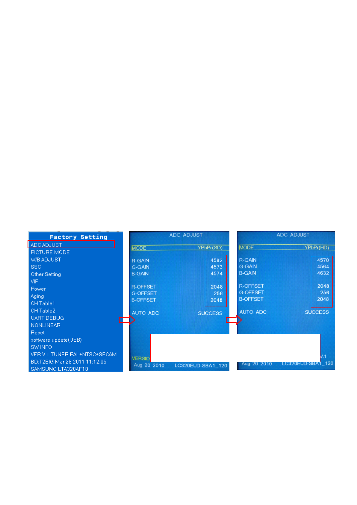
RecordedthewhitebalancedataofVGA/YPBPRsignalsourceinfactorymenubeforeupgrading(FLASH
initializationmayoccuraftertheupgrade,flushcolorcalibrationdata,thenrestorethedatayouhavebeen
recorded):
(1).IntheconditionofYPbPbmessagesource,presstheMENUbuttonafterappearthemainmenu,then
followedby8202numberkeystoenterthefactorymenu,selectADCADJUSTitem,presstheOKkeytoenter
thenextlevelmenu,movethecursortotheMODEitem,presstheleft/rightMovingbuttonandmovethe
cursorselectioninYPbPr(SD)item,recordtheR-GAIN/G-GAIN/B-GAINvalueand
R-OFFSET/G-OFFSET/B-OFFSETvalue.
(2).IntheADCADJUSTitem,pressOKkeytoenterthenextlevelmenu,movethecursortotheMODEitem,
presstheleft/rightcursorkeystoselectYPbPr(HD)item,recordR-GAIN/G-GAIN/B-GAINvalueand
R-OFFSET/G-OFFSET/B-OFFSETvalue.
V4.5.2.8.SZ.exe
software
upgrades
upgrades
upgrades(
(
A
(
After
(A
ervice)
RecordtheR/G/B-GAINandR/B/G-OFFSETvalueunderthe
YPbPr(SD)andYPbPr(HD)mode,tobereplacedtherecorded
valueafterthemachinesoftwareupgrade
3、Operationsandprocedureofsoftwareupgrading:
(1).Changedthefilenameto"MERGE.bin",thenstoresoftwareintheFAT32formatblankUdisk.
(2).InsertUSBflashdiskintotheUSBupgradeport,upgradethesoftwareaccordingtothefollowingthe
operatinginstructions::
Method1(Method1willnoterasetheoriginalEDIDandHDCPKEYonmainboard.Easyoperation,you
onlyneedoneUdisktoupgrade.Sowerequirecustomerusethiswaytoupgrade.) :
①.Startthemachineandwaitthenormalpicturedisplay,presstheMENUbuttonontheremotecontrol,will
bepoppingupthemainmenu,pressthe8202numberkeysandentertheFactorySettingmenu.
②.Pressup/downkeystomovethecursorto"softwareupdate(USB)"functionmenu,thenpressrightkeyto
select"YES",toimplementUSBupgradecommand:
a.Afterprompt"Filesysteminiterror",meansthatthemachinehavefoundUSBdevice,butdidnotfindthe
needingupgradesoftware,pleasecheckthesoftwarenameiscorrectorformattheUdiskagainandthencopy
software.
38
Page 40
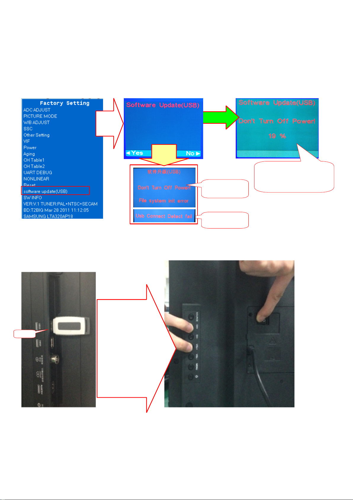
b.Afterprompt"USBConnectDetectfail",meansthatthemachinedoesnotfindUSBdevice,checkifthe
USBdevicehasbeeninsertedinto,orchangeanotherUdiskandtryagain.
③.Displaypercentageprogresspromptsandabout10secondslater,themachineblackscreenandrestart
automatically,meansthatthemachinecompletetheupgradeprocess,turnoffthemachinefirst,thenpullout
theUdisk.
Press
OK
key
升级
异常
Abnormal
Upgrading
Didnotidentify
upgradefile
Didnotidentify
theUdisk
Whensoftwareupgrading
completed,themachine
restartautomatically,and
thendisplaythismenu
Method2:KeeppressingVOL+andCH+keysonthemachinepanel,poweronthemachine,thestandbylight
flashesquicklyafterabout5seconds,standbylightgoesoutandturnintolightingafteraboutaminute,means
thatupgradeiscompleted.
will
Method2:Keep
pressingVOL+and
CH+keysonthe
machinepanel,
Udisk
poweronthe
machine,the
standbylightflashes
quicklyafterabout5
seconds,standby
lightgoesoutand
turnintolightingafter
aboutaminute,
meansthat
upgradeis
completed.
(3).Notices:
①.WhenthemachineUpgrading(Udisklightflash),donotremoveUdiskorswitchoffthepower,otherwiseit
willdestroythesoftwareandleadcannotupgrade.
②.ThemachinemustbepoweroffwheninsertedorpulledoutUdisk,toavoiddamagingUdiskormachine.
③.BecauseofcompatibilitybetweenmachineandUdisk,somemachineswillnotflickerduringupgrading.
PleasechangeUdisk(ThecapacityofUdiskisnotmorethan2G)orusemethod1toupgrade.
④.Ifthedisplayscreencan'tdisplaymenunormally,itcannotuse"method1"toupgrade,youcanuseMstar
39
Page 41
ISPToolstoupgradeexceptmethod1andmethod2.
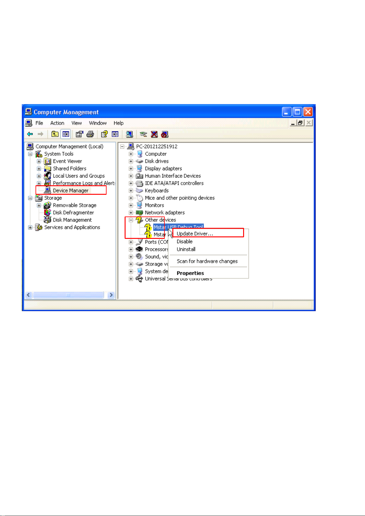
4、 Whencannotupgradeinaccordancewiththesteptwo,orupgradefailed,canonlyISPupgrade,pleaserefer
tothefollowinginstructions.
(1).ConnecttheISPburningboardandTVVGAportwithVGAcable.
Tool
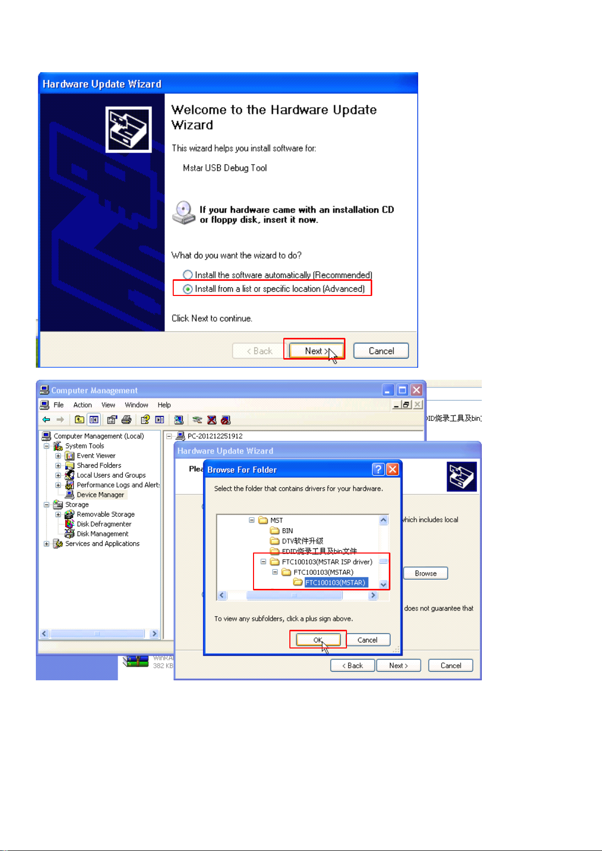
(2).InserttheMstarUSB
intotheUSBportofyourPC.ThePCcanrecognizethenewdevice.Youcan
choosetoinstallitinthelist,orchoosetoinstallataspecifieddirectoryandspecifythepathtothedrivefile.
Seethefigurebelow:
40
Page 42
41
Page 43
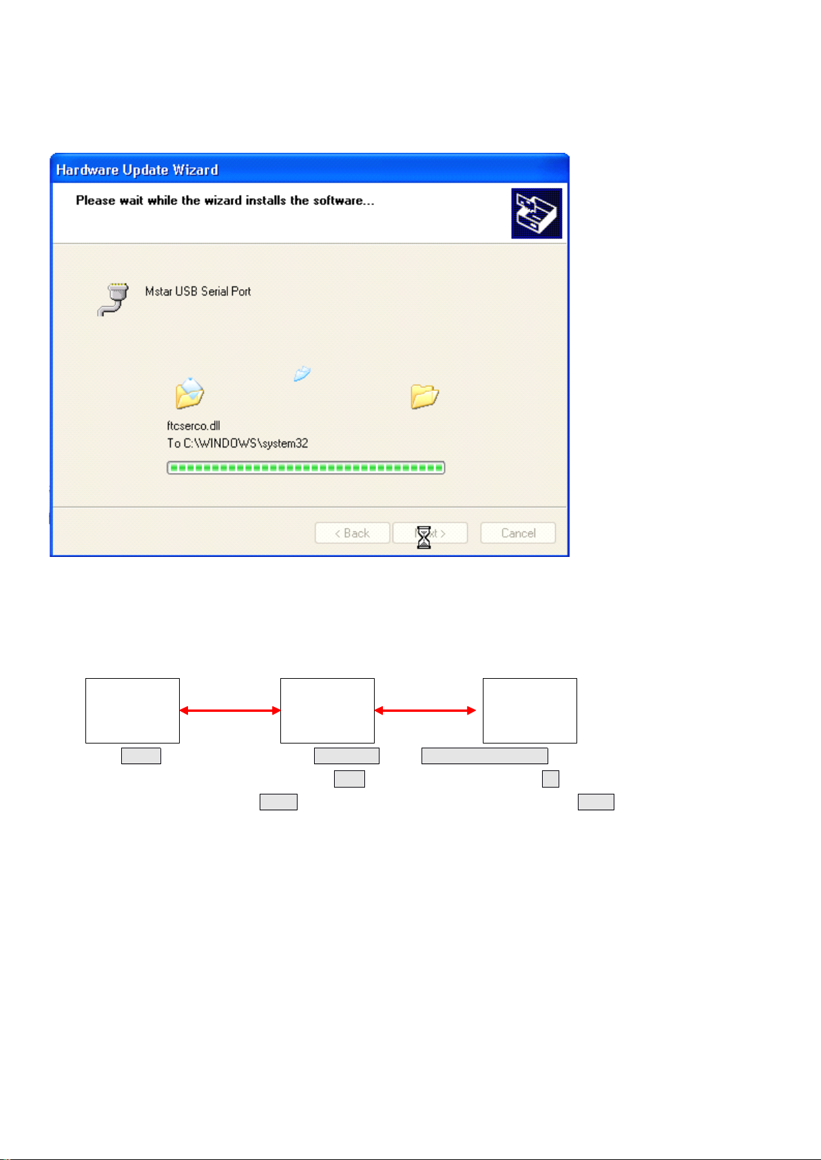
(3)WhenPCfindsthedrivefile,itwillgivethepromptsasinthefigurebelowduringtheinstallationprocess.
Pleaseclick“Continue"togoahead.Thesystemwillgothroughthreedriveinstallationprocesses,including
MstarUSBDebug
A,MstarUSBDebug
Tool
B,andMstarUSBSerialPort.Theywillbeinstalledoneby
Tool
one.
C.Programburning
1.Whenthedrivesareinstalled,connecttheMstarUSB
Tool
boardtoTVinsuchawayasspecifiedbelow.
Then,connecttheTVpowercordandrunthesoftwareISP-ToolV4.5.2.8.SZ.exetoburntheprogramintothe
TVdriveboard..
ComputerTVVGA
USBcable
ISP
burning
VGAcable
socket
board
2.IntheconfigmenubartoselectUseUSBandAutoreleaseUSB,CommunicationSettingitems
correspondingtothePortTypemenuselectUSB。Settheburningspeedof48inI2CSpeedSettingitem,ISP
SlaveAddressitemmenuselectOX92,SerialDebugSlaveAddressmenuselect0XB2。
42
Page 44
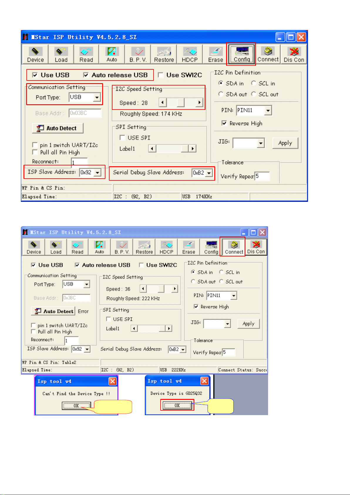
(3).ClickConnectbuttontoconnect,ifitprompts“DeviceTypeisGD25Q32”,meansthatnormalconnecting;if
itprompts“Can'tfindtheDeviceType!”meansthatthereispoorconnecting,pleasehaveacheck.
Abnormal
OK
(4).Click"Read"buttonintoolbar,thenclick"Read"toloadcurrentsoftware.
43
Page 45
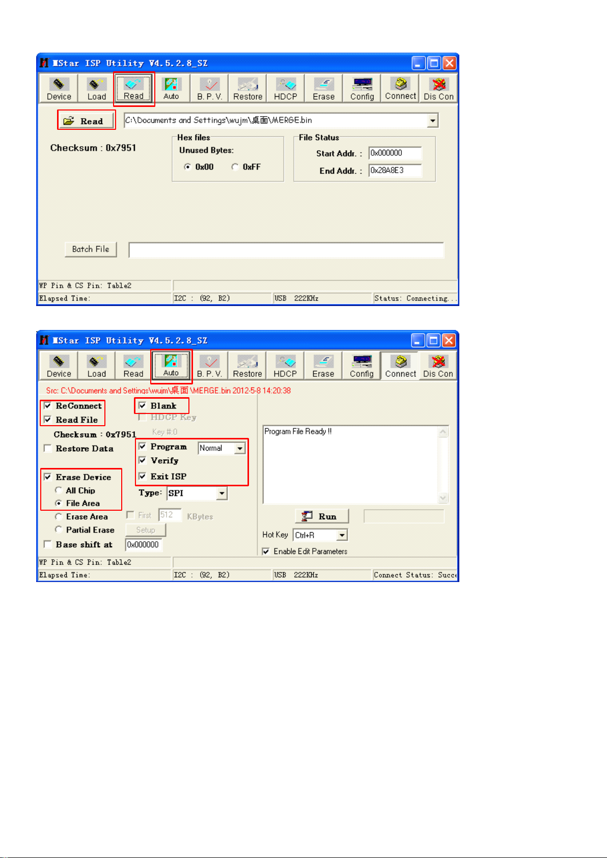
(5).Click"Auto"buttonintoolbartosetthecorrespondingsettings.
Thenclick“RUN”buttontoburnsoftware.
44
Page 46
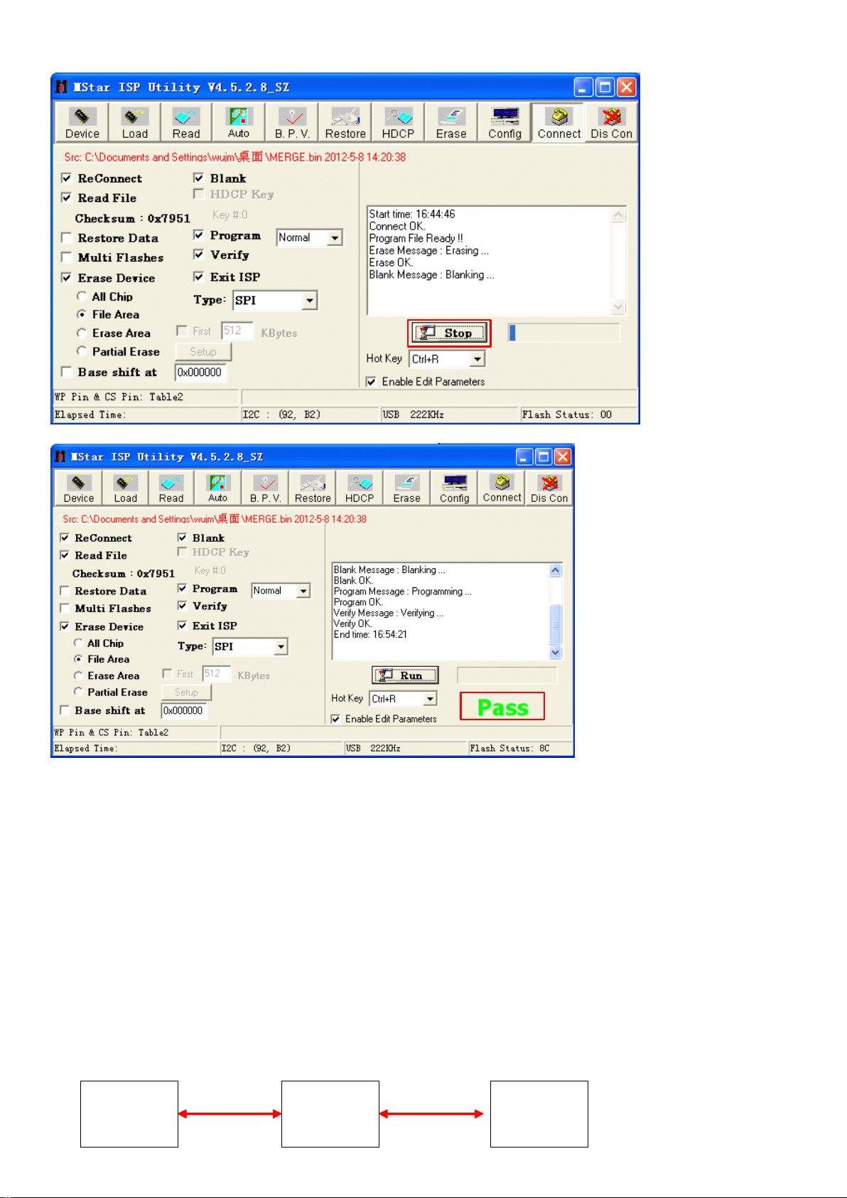
PASS
Whendisplay“PASS
PASS
PASS”,meansthatitsucceed,thenburnEDIDaccordingtothefollowinginstructions.
5、UseISPwaytoupgrade(whenusedUSBwaytoupgrade,itcoundn'terasetheoriginalEDIDandHDCP
KEYonmainboard,sowerequirecustomerusethiswaytoupgradefirst.),whenyouselected"ALLChip"
under"EraseDevice"optionduringupgrading,theTVmainboardmustburnEDIDandHDCP
KEY.
buringtoolsandmaterialsforHDCPKEYandEDID:
*
*
*
*Personalcomputer(WINDOWSXPsystem,USB2.0)
*
*
*
*AC100~240Vpowersupplyandpowercord
*
*
*
*ISPburningboard
*
*
*
*ISPburningboarddriver
*
*
*
*ISP_Tool_XC_V0.05.exe
*
*
*
*VGAcable
*
*
*
*VGAEDIDandHDMIEDIDfile
Specificoperationaccordingtothefollowinginstructions:
The
(1).ConnectISPburningboardandTVandcomputer,thenrunISP_Tool_XC_V0.05.exetosetcommunication
mode.
ComputerTVVGA
USBcable
ISP
burning
VGAcable
socket
board
45
Page 47
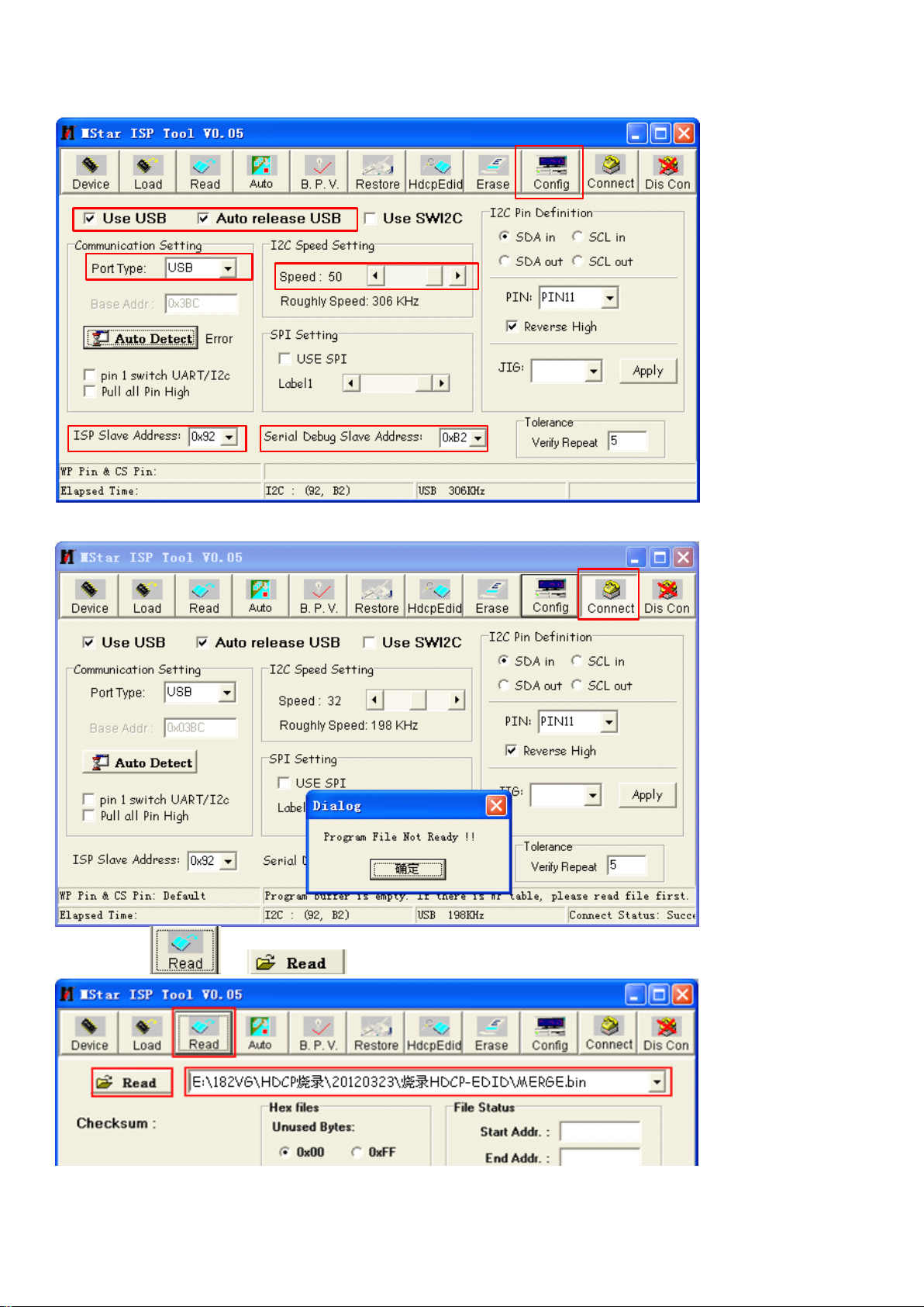
(2).ClickConnectbuttontoconnect,ifprompts“ProgramFileNotReady!"
Pleaseclickandtoloadcurrentsoftware.
Ifprompts“DeviceTypeisGD25Q32”meansthatnormalconnect;ifprompts“Can’tfindtheDeviceType!”
meansthatthereispoorconnecting,pleasehaveacheck.
46
Page 48
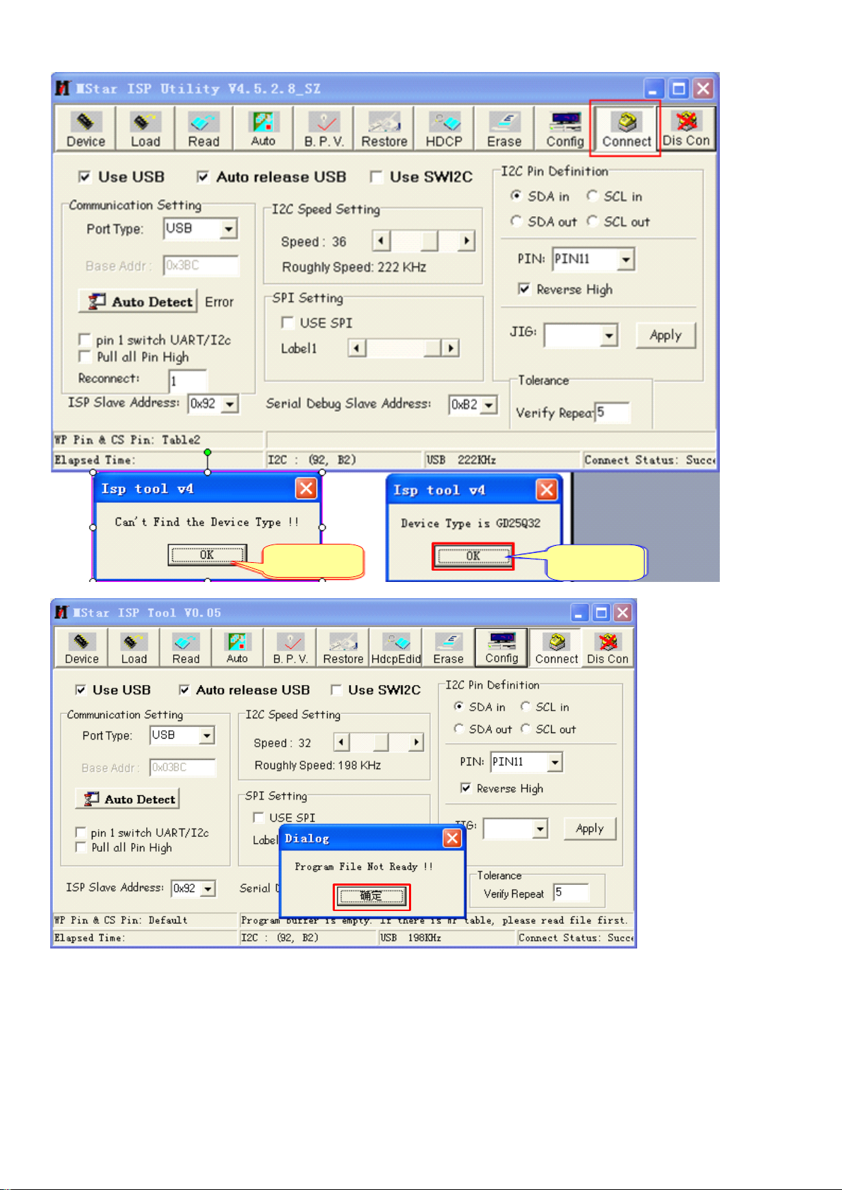
AbnormalOK
Ifprompts“DeviceTypeisGD25Q32”meansthatnormalconnect;ifprompts“Can’tfindtheDeviceType!”
meansthatthereispoorconnecting,pleasehaveacheck.
(3).ClickHdcpEdidbuttoninmainmenubartosetcorrespondingsettingsaccordingtothefollowing
instructions:
NeedtoburnHDCPKEY,pleaseselectandloadcurrentKEYdocuments,inKEYaddressbarinput"0
X3B0000"andenter;selectEDID1checkboxandloadcurrentworkorderVGAportEDID.binfile,inEDID1
correspondingfilesaddressbarinput"0X3B0400"andenter;selectEDID2checkboxandloadcurrentwork
orderHDMIEDID.binfile,inEDID2correspondingfileaddressbarinput"0X3B0600"andenter.ModifyEDID1
47
Page 49
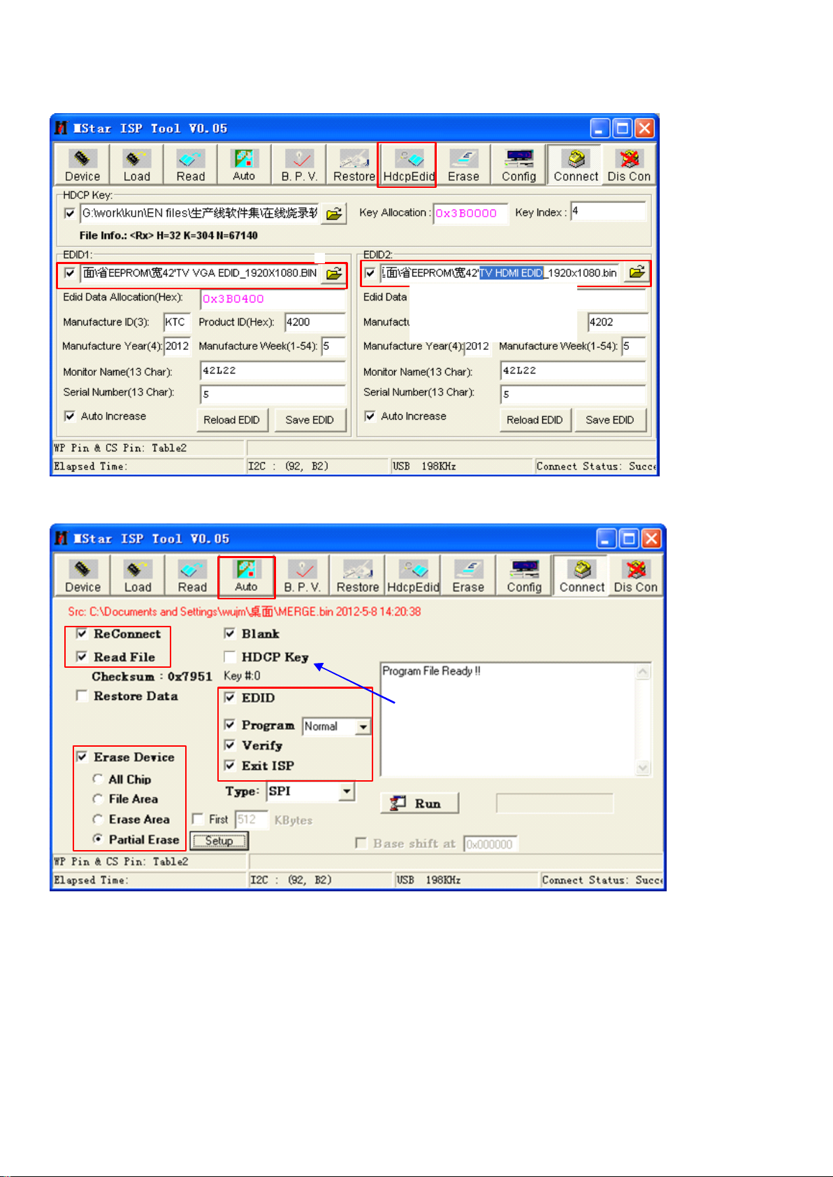
andEDID2correspondinginformationaccordingtoworkorder,confirmandclick"Auto"buttoninmainmenu
bartoswitchtoburningmaininterface.
Don'tselet,ifmainboard
haveburnedcorrectKEYor
EDID.
(4).Inburningmaininterface,selectcorrespondingfunction,clickSetupbuttoninEraseDevice,
Don'tselet,ifmainboardhaveburned
correctKEYorEDID.
toentertoEraseBlockSettingmenu,clickClearAlltoclear,clickdrop-downlistinGlobalOffsetAddress,
select"OX00000000,Bank00",inaddresslistselect"0X3B0000",checkaddresssettingsandclick"OK"button
toexitaddresssettings.
48
Page 50
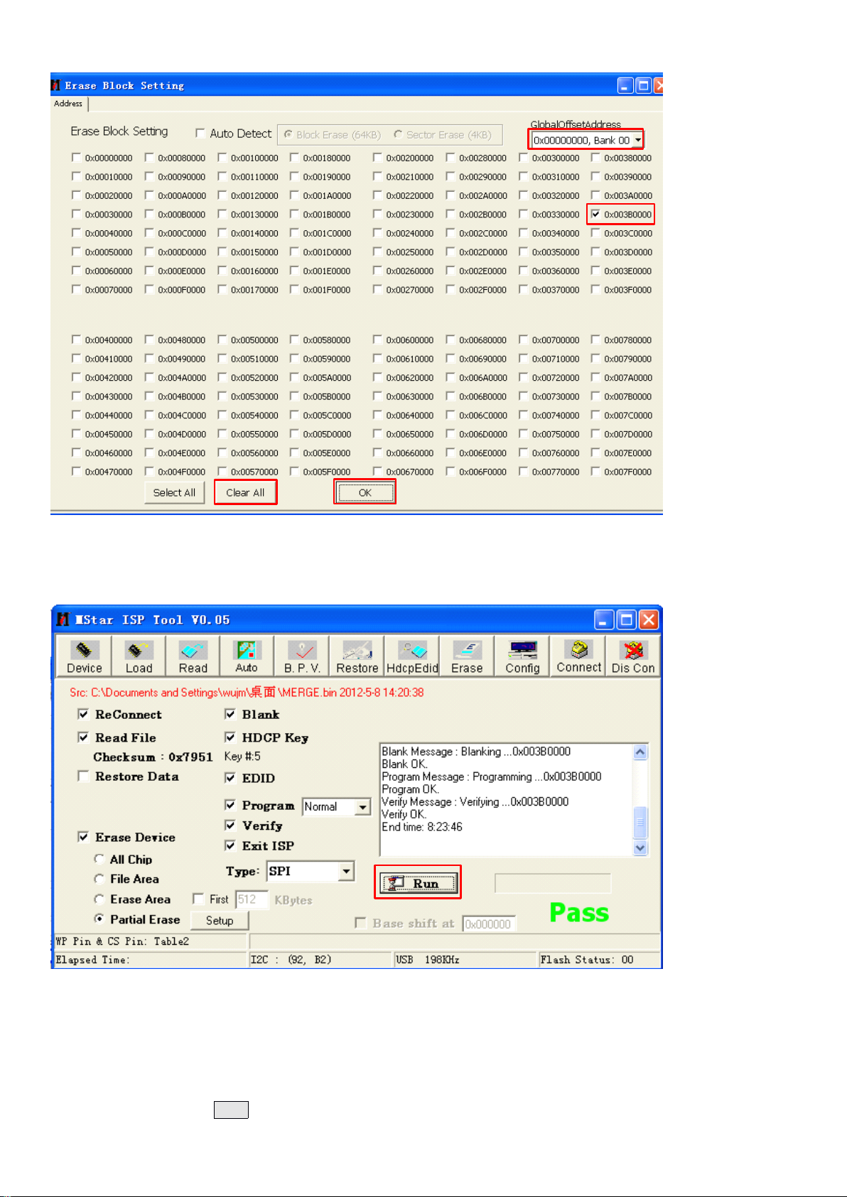
(5).Inburninginterface,click"Run"toburn.Burningpromptbarwillpromptburningprocessrelatedinformation,
about12secondsappear"Pass",andthereisnolongeranycharacterrollinginpromptbar,meansthatis
burningsuccessfully.
(6).Shutdownthepowerofjig,pullouttheburningwiretocompleteburningoperation.Itnotallowpullingout
thewiresduringburningprocess.Shutdownthepowerwheninstallingortakingmainboard.
(7).Itnotallowpullingoutthewiresduringburningprocess.Shutdownthepowerwheninstallingortaking
mainboard.Pulloutthepowercordofmachinefirst,thenpulloutburningboard.Whenburningcomplete,
Run
changetheTVandclickRun
Run
Run
buttontoburnnextmachine.
49
Page 51
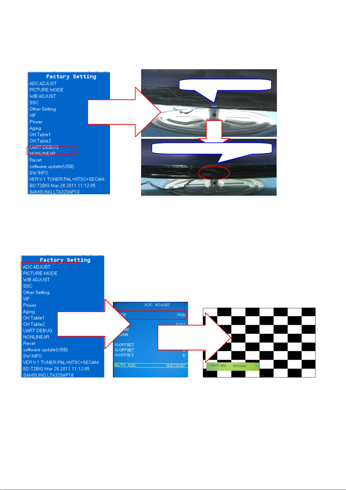
6、Whenupgradingcomplete,itmustbeadjustedbeforeleavefactory:
(1).Powertothemachine,pressMENUbuttonontheremotecontrolthenpress8202numberkeysandthenwillpoppingthe
factorymenuautomatically,presstheremotecontrolup/downcursorkeystomovetothe"Reset"optionpressOKkeyto
implement.Afterabout5secondslatterthemachineimplementclearcommandautomatically.Afterabout5secondslatterthe
will
screen
beblackanditflashesbluelanternpaneldisplay,itsaidthattheorderim plementsuccessfully.
Panelstandbylightbright,
PressOKkeyon
remotecontrolto
implementfactory
reset
Panelstandby
light
extinguish,reset
(2).Insertsignalcabletothemachine,switchtothePCmessagesource.
(3).RuntheKTC-LCDtestsoftware,switchtothemosaicpictureandbestresolution.PressMENUkeyto
popupthemainmenu,andthenpress8202numberkeystoenterthefactorymenu,presstheshiftdouwnkey
toADCADJUSToptiontopressOKkeytoenterthenextlevelmenu.IntheMODEoptionpressleft/rightcursor
keystoselectRGB,andthenpressshiftdouwnkeytomovethecursortotheAutoADCoption,pressOKkeyto
enterthenextlevelmenu,presstheleft/rightbuttontoimplementADCaction(ThescreenwillflashandAuto
ADCfunctionmenupromptSUCCESSmeansthatdebugsuccess,prompt
FAIL
saidthatdebugfailed,try
again),presstheMENUbuttontoexitfactorymenuwhendebuggingcompleted.
PressOKkeyon
remotecontrolto
implementfactory
reset
PressOKkeyon
remotecontrolto
implementfactory
reset
(4).UndertheYPbPbmessagesource,presstheMENUbuttonafterpoppingthemainmenu,thenpress8202
numberkeystoenterthefactorymenu,selectADCADJUSTitem,presstheOKkeytoenterthenextlevel
menu,movethecursortotheMODEitem,presstheleft/rightMovingkeymovercursortoselect
YPbPr(SD)item,changetheR-GAIN/G-GAIN/B-GAINvalueandR-OFFSET/G-OFFSET/B-OFFSETvalueof
themachineaftertheupgradetothevaluebeforetheupgrade.
50
Page 52
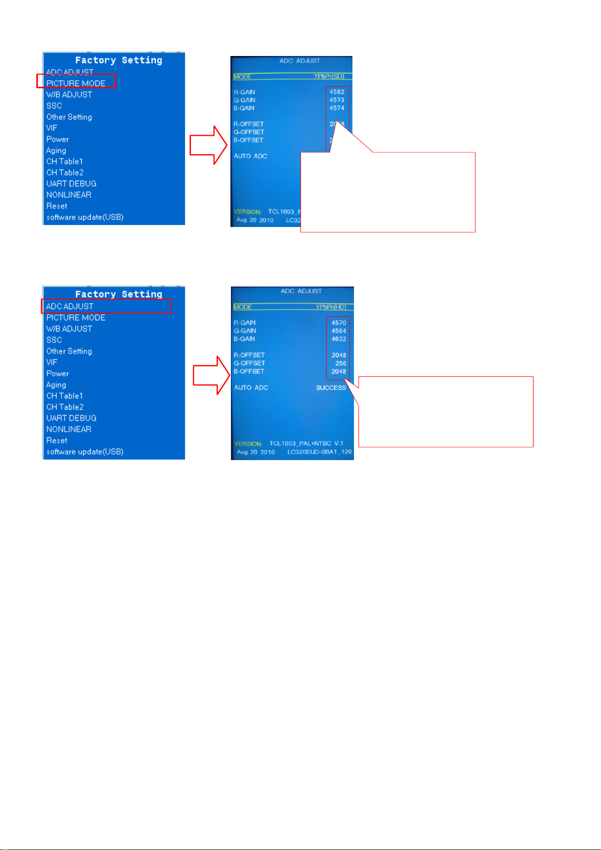
Changethe
R-GAIN/G-GAIN/B-GAINvalueand
R-OFFSET/G-OFFSET/B-OFFSET
valuetothevaluebeforethe
upgradeundertheYPbPr(SD/HD)
mode
(5).IntheADCADJUSTitem,pressOKkeytoenterthenextlevelmenu,movethecursortotheMODEitem,
presstheleft/rightkeystomovecursorselecttheYPbPr(HD)item,changetheR-GAIN/G-GAIN/B-GAINvalue
andR-OFFSET/G-OFFSET/B-OFFSETvalueofthemachineaftertheupgradetothevaluebeforethe
upgrade.
Changethe
R-GAIN/G-GAIN/B-GAINvalueand
R-OFFSET/G-OFFSET/B-OFFSET
valuetothevaluebeforethe
upgradeundertheYPbPr(SD/HD)
mode
7、 CompletetheADCADJUSTdebugging,pressMENUkeysuccessiontoexitthefactorybuilt-inmenutosave
theadjusteddata,andthenrestoretheoriginalpackaging.
51
Page 53
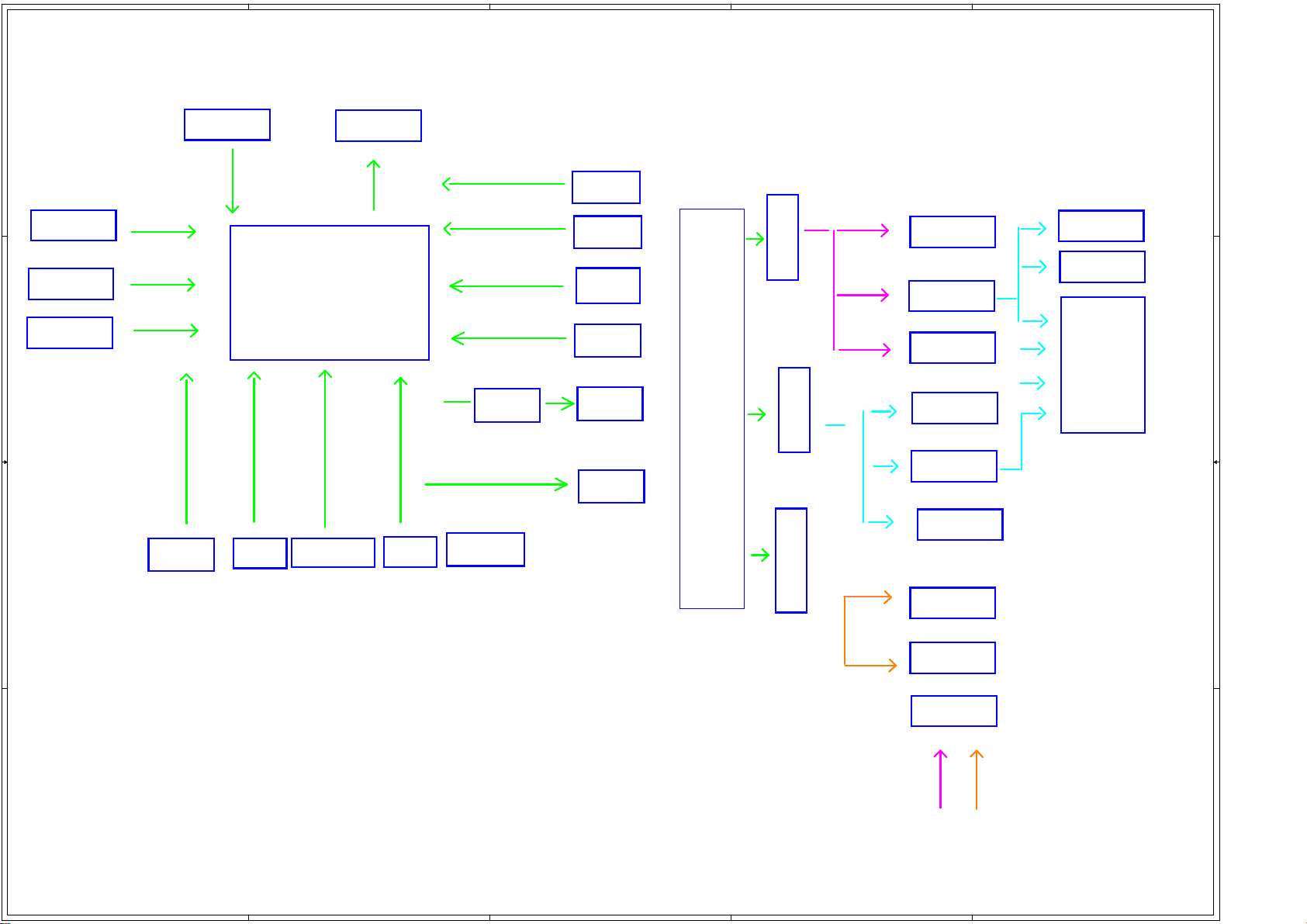
5
A
A
AV_OUT
4
3
2
1
TSUM V59MS T9B
Block diagram
TSUM V59MS T9B
power supply diagram
D D
FLASH
KEY BOARD
UART
C C
POWER
LVDS
TSUM V59MS
AO
USB2
USB1
AV
TUNER
EARPHONE
AMP
POWER
5V_standby
5V_NORMAL
5V_NORMAL
KEYBOARD
1117-3.3V
8008-1.26V
1117-1.8V
1084-3.3V
FLASH
UART
V59MS
AVOUT
HDMI2HDMI1
B B
YPBPR、AV2
VGA
12V_NORMAL
AO
AMP
LVDS
5V_NORMAL
12V_NORMAL
5
4
3
2
52
Page 54
5
A
A
BPF_IN
SDA
r
SDA
1uf
1uf
4
3
2
1
HDMI2
CON6
CON6
21
21
26
26
25
25
24
24
D D
22
22
23
23
20
20
HDMI1
HDMI1
HDMI/SMD/CON/A
C C
TUNER
TUNER_CONNECTOR
TUNER_CONNECTOR
CON8
CON8
B B
DATA2+
DATA2 SHIELD
DATA2-
DATA1+
DATA1 SHIELD
DAT1A-
DATA0+
DATA0 SHIELD
DATA0-
CLK+
CLK SHIELD
DDC/CECGND
+5V POWER
HOT PLUG
1
2
3
4
C46
C46
1NF/2KV
1NF/2KV
C40
C40
4.7NF/1KV
4.7NF/1KV
C66
C66
4.7NF/1KV
4.7NF/1KV
C53
C53
10NF/1KV
10NF/1KV
C64
C64
10NF/1KV
10NF/1KV
C54NCC54
1
2
3
4
5
6
7
8
9
10
11
12
CLK-
13
CEC
14
NC
15
SCL
16
17
18
19
R1491KR149
1K
Q18
Q18
MMBT3904
MMBT3904
R1601kR160
1k
HDMIB_+5V
HDMIB_+5V
R157
R157
47k
47k
HDMI_HP0
HDMIB_+5V
R152 10KR152 10K
R154 10KR154 10K
200R
200R
R25
R25
HDMI_HP0
High frequency differential circuit
3.3V_Tun
TR10 4.7KTR10 4.7K
C51
1NF/2KV
1NF/2KV
TL4
TL4
330nH 140mA 5%
330nH 140mA 5%
NC
100pF 100V/5%
100pF 100V/5%
TL3
TL3
C142 82pF 50VC142 82pF 50V
TC37
TC37
150pF 50V ?%
150pF 50V ?%
220nH 120mA 5%
220nH 120mA 5%
TC36
TC36
TC35
TC35
100pF 100V/5%
100pF 100V/5%
C51
TR11 4.7KTR11 4.7K
RFIN
TC30
TC30
0.1uF
0.1uF
1
RFVCC
2
GPO_RFAGC_SEN
3
GPIO2
4
GNDRF1
5
RFIN
6
GNDRF2
7
LTO(214)
8
STO
9
CAPsmooth
10
NC
11
GNDDIO
12
AS_SCAN1
HDMI0-RX2P
HDMI0-RX2P
HDMI0-RX2N
HDMI0-RX2N
HDMI0-RX1P
HDMI0-RX1P
HDMI0-RX1N
HDMI0-RX1N
HDMI0-RX0P
HDMI0-RX0P
HDMI0-RX0N
HDMI0-RX0N
HDMI0-CLKP
HDMI0-CLKP
HDMI0-CLKN
HDMI0-CLKN
HDMI-CEC
HDMI0-SCL
HDMI0-SCL
HDMI0-SDA
HDMI0-SDA
HDMIB_+5V
C139
C139
0.1uF/NC
0.1uF/NC
TC25
TC25
220NF
220NF
48
49
47
E-PAD
CAPRFAGC
TU2
TU2
TDA18274HD
TDA18274HD
XtallnSEL13SCL14SDA15GNDDIG16XTAL17XTALn18CapRegVco19GNDSYN20VT21CP22VCCSYN23XTOUT1
C146
C146
33pF
33pF
Y3 16MHzY3 16MHz
21
22
23
20
3.3V_Tun
41
40
GNDRF542GNDRF443GNDRF344GNDRF245GNDRF146GNDRF0
VCCRFFilte
TC34
TC34
TC31
TC31
C145
C145
33pF
33pF
0.1uF
0.1uF
6.8NF
6.8NF
TC44
TC44
100pF
100pF
CON7
CON7
DATA2+
21
DATA2 SHIELD
DATA2-
DATA1+
DATA1 SHIELD
DAT1A-
DATA0+
DATA0 SHIELD
DATA0-
CLK SHIELD
22
23
DDC/CECGND
+5V POWER
HOT PLUG
20
HDMI2
HDMI2
HDMI/SMD/CON/A
VSYNC_SCAN
IRQ_SCAN
SCANOUT1
24
TR9 430RTR9 430R
TR16 100RTR16 100R
TR15 100RTR15 100R
TC42
TC42
100pF
100pF
HDMI1
IFP
IFN
HDMI1-RX2P
HDMI1-RX2N
HDMI1-RX1P
HDMI1-RX1N
HDMI1-RX0P
HDMI1-RX0N
HDMI1-CLKP
HDMI1-CLKN
HDMI1-SCL
HDMI1-SDA
HDMIA_+5V
1
2
3
4
5
6
7
8
9
10
CLK+
11
12
CLK-
13
CEC
14
NC
15
SCL
16
17
18
19
R1501KR150
1K
Q19
Q19
MMBT3904
MMBT3904
GNDRF937GNDRF838GNDRF739GNDRF6
36
GNDRF10
35
GNDRF11
34
GNDRF12
33
32
31
VIFAGC
30
VCCIF
29
GNDIF1
28
IF
27
IFN
26
25
XTOUT2
1K1K2T2T3C
3C
3.3V_Tun
TC41 2.7NFTC41 2.7NF
TC43 220NFTC43 220NF TC26
TR12
TR12
TR13
TR13
10K
10K
10K
10K
C700 47nFC700 47nF
HDMIA_+5V
HDMIA_+5V
R151 10KR151 10K
R153 10KR153 10K
HDMIA_+5V
R158
R158
47k
47k
HDMI_HP1
R1611kR161
1k
3.3V_Tun
TC40 0.1uFTC40 0.1uF
TC39 0.1uFTC39 0.1uF
SDA
SDA
SCL
SCL
3.3V_Tun
R28 1KR28 1K
C31
C31
6.8nF
6.8nF
HDMI_HP1
TAGC
IFP
IFN
C138
C138
0.1uF/NC
0.1uF/NC
AGND
HDMI1-RX2P
HDMI1-RX2N
HDMI1-RX1P
HDMI1-RX1N
HDMI1-RX0P
HDMI1-RX0N
HDMI1-CLKP
HDMI1-CLKN
HDMI-CEC
ARC
HDMI1-SCL
HDMI1-SDA
+12V_NORMAL
+5V_Normal
PCB
PANEL POWER
L9 BEAD/ncL9 BEAD/nc
L10 BEADL10 BEAD
Voltage selection approach
TO MASTER CH IP
TC32
TC32
10NF
10NF
PANEL_ON/OFF
C52
C52
0.1uF
0.1uF
C53
C53
0.1uF
0.1uF
GND
C367
3.3V_Tun
TC26
1uF
1uF
TC27
TC27
47NF
47NF
1
2
3
4
J2
J2
25X21mm
25X21mm
C802
C802
100PF
100PF
C813
C813
100PF
100PF
PANEL_ON/OFF
屏蔽罩
屏蔽罩
R806 100RR806 100R
R815 100RR815 100R
TC29
TC29
TC28
TC28
10NF
10NF
47NF
47NF
VCC-PL
C136
C136
R148
R148
100K
100K
+3.3V_NORMAL
R156
R156
10K
R155
R155
4.7K
4.7K
R162
R162
10K/NC
10K/NC
R159
R159
4.7K
4.7K
10K
Q17
Q17
MMBT3904
MMBT3904
TUNER AGC,Close TUNER
VIFP
VIFP
VIFM
VIFM
VCC-PL
Q16
Q16
WPM3401
WPM3401
SOT23
1
CA4
CA4
100uF/16V
100uF/16V
VCC-Panel
32
1
TP7NCTP7
NC
+
+
C137
C137
0.1U
0.1U
53
5
4
3
2
Page 55
5
A
A
Pr
Pr
AUDIO O UT
4
3
2
1
VGA
R80
R80
10K
P1
P1
PHONEJACK
PHONEJACK
8
PC-R
PC-L
PC-R
7
2
PC-L
1
4
5
3
10K
R81
R81
10K
10K
C114
C114
电脑音频输入接口
D D
P2
5
15
10
4
14
9
3
13
8
2
12
7
1
11
0R/NC
0R/NC
6
16
17
VGAP2VGA
XVGA
R17
R17
C C
0R/NC
0R/NC
R18
R18
R102
R102
R103
R103
75R
75R
75R
75R
R105
R105
UART-TX
R106
R106
UART-RX
22R
22R
22R
22R
UART-TX
UART-RX
VGA-HS
AV1
AV1-V
AV1-L
C127
C127
200p/nc
200p/nc
R130
R130
10K
10K
R135
R135
12K
12K
R125
R125
33R
33R
R128
R128
75R
75R
C128
C128
1NF
1NF
1NF
1NF
R104
R104
75R
75R
AV-CVBS0P
AV_AULin0
VGA-Lin
VGA-Lin
VGA-Rin
VGA-Rin
C115
C115
R83
R83
R82
R82
12K
12K
1NF
R90 33RR90 33R
R95 33RR95 33R
R96 33RR96 33R
R100 33RR100 33R
1NF
RGB0_Pb+
RGB0_Pb+
RGB0_Y-SOG
RGB0_Y-SOG
RGB0_Y+
RGB0_Y+
VGA_Rin
RGB0_Pr+
R107
R107
100R
100R
VGA_HS
VGA-VSVGA-VS/
R108
R108
100R
100R
C121
C121
22P
22P
CN3
CN3
YPbPr_IN
YPbPr_IN
Y&AV2
Y&AV2
Pb
Pb
R131
R131
75R
75R
C122
C122
22P
22P
YPBPR
R133
R133
R132
R132
75R
75R
75R
75R
R110
R110
10K
10K
TO MASTER CHIP
VGA_HS
VGA_VS
R112
R112
10K
10K
NEAR MASTER CHIP
R124 33RR124 33R
R126 33RR126 33R
R127 33RR127 33R
R129 33RR129 33R
RGB2-HDTV_SOGIN
RGB2-HDTV_GIN
RGB2-HDTV_BIN
RGB2-HDTV_RIN
12K
12K
AV_OUT
CN2
CN2
AV_VOUT
LOUT
AV_OUT
AV_OUT
ROUT
EPRPHONE
AMP-AUOUTL02
CN1
CN1
PHONEJACK
PHONEJACK
678
AV_VOUT
C120
C120
20pF
20pF
+12V_NORMAL
AMP-AUOUTL0
R30
R30
100K
100K
Q12
Q12
R93
R93
75R
75R
R113 100RR113 100R
C44
C44
200p
200p
5
4
2
1
3
3906
3906
3 2
C1252.2u C1252.2u
2.7K
2.7K
EARPHONE-LOUT
EARPHONE-ROUT
HP_MUTE_AMP
VIDEO O UT
1
R94
R94
75R
75R
CA2
CA2
+
+
100uF/16V
100uF/16V
R118
R118
R87
R87
330R
330R
Q13
Q13
3904
3904
C123
C123
0.1u
0.1u
R116
R116
R120
R120
OP_VCC
47K
47K
8.2K
8.2K
+5V_Normal
2 3
R97
R97
75R
75R
LOUT
R88
R88
20K
20K
CA6
CA6
+
+
1
R98
R98
R114
R114
100R
100R
Q14
Q14
1
3904
3904
R121
R121
22R
22R
CVBS_OUT0
CVBS_OUT0
100uF/16V
100uF/16V
12K
12K
AMP-L
2 3
AMP-AUOUTR02
EARPHONE-LOUT
EARPHONE-ROUT AMP-R
R143
R143
10K/NC
10K/NC
AMP-AUOUTR0
R31
R31
100K
100K
R144
R144
10K/NC
10K/NC
R89
R89
100K
100K
ROUT
R99
R99
100K
100K
C1262.2u C1262.2u
C45
C45
200p
200p
CT1
CT1
CT2 10uFCT2 10uF
10uF
10uF
C132
C132
47NF/NC
47NF/NC
C116
C116
R86
R86
47R
47R
2.2uF
2.2uF
R92
R92
C119
C119
47R
47R
2.2uF
2.2uF
OP_VCC
C124
C124
R115
R115
0.1u
0.1u
R117
R117
R119
R119
2.7K
2.7K
47K
47K
1
3904
3904
R122
R122
R123
R123
8.2K
8.2K
AMP-L
C133
C133
47NF/NC
47NF/NC
R33
R33
100K/nc
100K/nc
100R
100R
Q15
Q15
22R
22R
R35
R35
100K/nc
100K/nc
2 3
AMP-R
C49
C49
180p/NC
180p/NC
C61
C61
180p/NC
180p/NC
AV-AUOUTL3
AV-AUOUTR3
AV1-R
R136
B B
R136
10K
10K
R138
R138
12K
12K
CN4
CN4
AV1_IN
AV1_IN
5
AV1-V
AV1-R
AV1-L
C129
C129
1NF
1NF
AV_AURin0
AV2
CN5
CN5
HD_AUDIO_IN
HD_AUDIO_IN
Y&AV2
C43
C43
200p/nc
200p/nc
HD_L
R141
R141
10K
HD_R
10K
R142
R142
10K
10K
HD_L
1
3
HD_R
2
4
4
AV-CVBS1P
R29
R29
33R
33R
YPBPR_L 2
C131
C131
R164
R164
1NF
1NF
12K
12K
C134
C134
1NF
1NF
YPBPR_R 2
3
R163
R163
12K
12K
P3
SHIELD
SHIELD
USB_4PP3USB_4P
VCC
DD+
GND
USB
+5V_USB
1
2
3
4
5
6
0R
R1390RR139
0R
R1450RR145
USB1_D-
USB1_D-
USB1_D+
USB1_D+
+5V_USB
L8
+5V_Normal
FB_100RL8FB_100R
+
+
C130
C130
CA3
CA3
0.1u
0.1u
100uF/16V
100uF/16V
2
P4
SHIELD
SHIELD
USB_4PP4USB_4P
+5V_USB
0R
R1400RR140
0R
1
VCC
2
D-
3
D+
4
GND
5
6
R1460RR146
USB0_D-
USB0_D-
USB0_D+
USB0_D+
54
Page 56
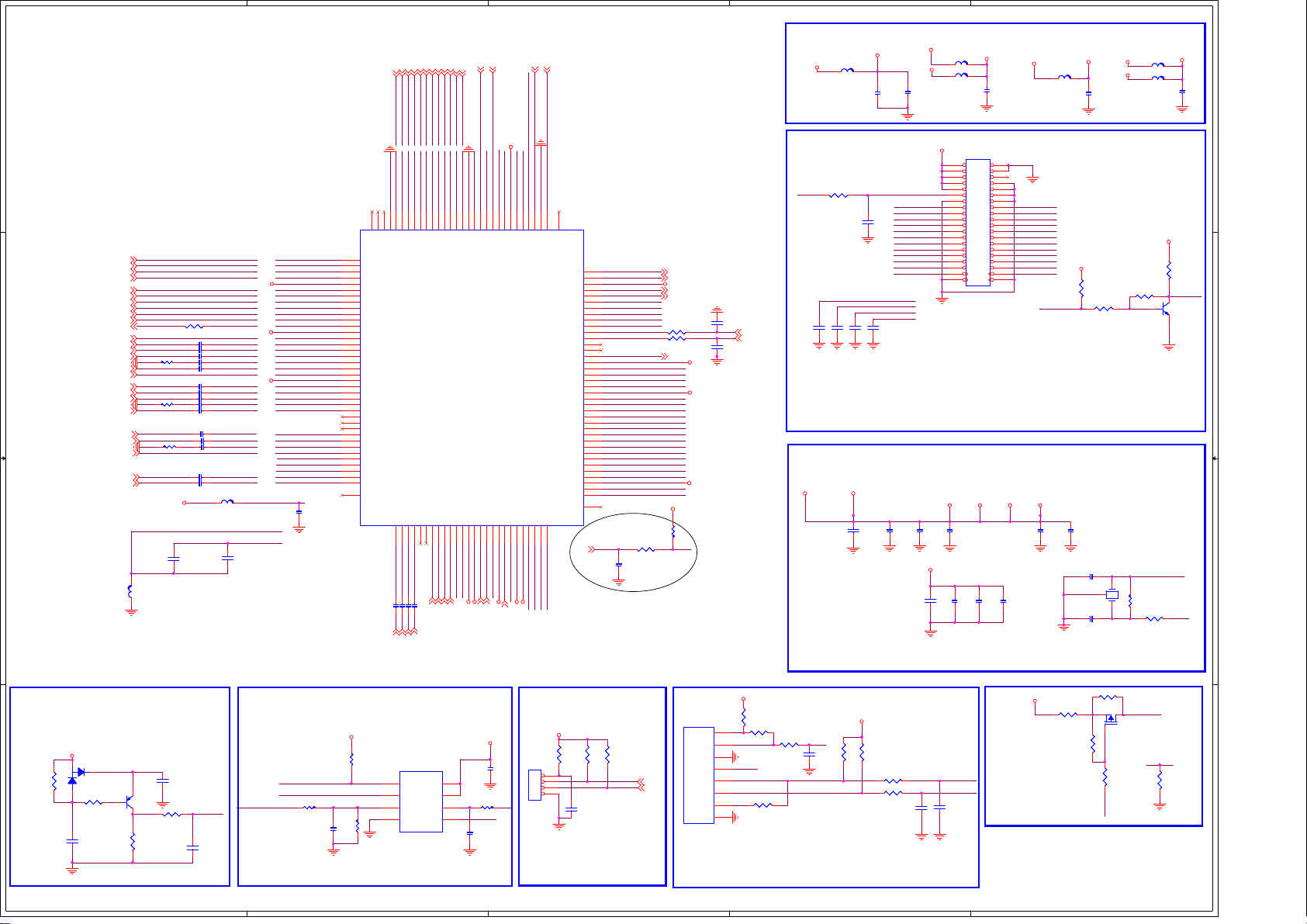
5
A
A
K
A
A
with width trace
SCK
TSUMV59MS
TSUMV59MS
RX0N_A3RX0P_A4RX1N_A6RX1P_A
RX2N_A
RX2P_A
SCK
TSUMV59MS
D D
HDMI1-CLKN7
HDMI1-CLKP7
HDMI1-RX0N7
HDMI1-RX0P7
HDMI1-RX1N7
HDMI1-RX1P7
HDMI1-RX2N7
HDMI1-RX2P7
VGA_HS5
C C
B B
RGB0_Pb+5
RGB0_Y-SOG5
RGB0_Y+5
RGB0_Pr+5
VGA_VS5
RGB2-HDTV_BIN4
RGB2-HDTV_SOGIN4
RGB2-HDTV_GIN4
RGB2-HDTV_RIN4
HDMI1-CLKN
HDMI1-CLKP
HDMI1-RX0N
HDMI1-RX0P
HDMI1-RX1N
HDMI1-RX1P
HDMI1-SDA DDCDA_DA
HDMI1-SDA7
HDMI1-RX2N
HDMI1-RX2P
HDMI1-SCL DDCDA_CK
HDMI1-SCL7
ARC HDMI1-ARC
ARC7
VGA_HS
RGB0_Pb+
RGB0_Y-SOG
RGB0_Y+
R208 68RR208 68R
RGB0_Pr+
VGA_VS
RGB2-HDTV_BIN
RGB2-HDTV_SOGIN
RGB2-HDTV_GIN
R207 68RR207 68R
RGB2-HDTV_RIN
4
AV-CVBS1P
AV-CVBS0P CVBS0P
AV-CVBS0P4
CVBS_OUT04
AV_AULin04
AV_AURin04
R209 68RR209 68R
AV_AULin0 AUL0
Close to IC
L103FBL103
FB
R206 47RR206 47R
C191 47nFC191 47nF
C183 1nFC183 1nF
C151 47nFC151 47nF
C152 47nFC152 47nF
C190 47nFC190 47nF
C150 47nFC150 47nF
C180 1nFC180 1nF
C182 47nFC182 47nF
C181 47nFC181 47nF
C149 47nFC149 47nF
C193 2.2uFC193 2.2uF
C192 2.2uFC192 2.2uF
AU33
C170
C170
0.1uF
0.1uF
C172 47nFC172 47nF
C158 47nFC158 47nF
C153 47nFC153 47nF
BIN0
SOGIN0
GIN0P
GIN0M
RIN0
BIN2
SOGIN2
GIN2P
GIN2M
RIN2
CVBS1PAV-CVBS1P
VCOM0
CVBS_OUT0
FB_120R
FB_120R
L11
L11
VDDC
C171
C171
10uF
10uF
VDD33
AVDD_ADC
AUR0AV_AURin0
AU33v
AUVRM
AUVAG
HDMI1-CLKN
HDMI1-CLKP
HDMI1-RX0N
HDMI1-RX0P
HDMI1-RX1N
HDMI1-RX1P
DDCDA_DA
HDMI1-RX2N
HDMI1-RX2P
DDCDA_CK
HDMI1-ARC
VGA_HS
BIN0
SOGIN0
GIN0P
GIN0M
RIN0
VGA_VS
BIN2
SOGIN2
GIN2P
GIN2M
RIN2
CVBS1P
CVBS0P
VCOM0
CVBS_OUT0
AU33v
AUVRM
AUVAG
AUL0
AUR0
0.1uF
0.1uF
C98
C98
FLASHRESET
+5V_Standby
3
R701MR70
1M
2
D4
BAV99D4BAV99
1
1
R74
R74
4.7K
4.7K
C112
C112
4.7u
4.7u
C107
C107
2.2UF
2.2UF
Q11
Q11
3906
3906
3 2
R79
R79
22K
22K
高电平复位
R76
R76
100R
100R
System-RST
C1131nC113
1n
SPI_WP0N
SPI_CS0N
SPI_Flash-SDO
TO MASTER CHIP
R771KR77
1K
C111
C111
0.1u
0.1u
U16
U16
1
2
5
7
8
9
10
11
12
13
14
15
16
17
18
19
20
21
22
23
24
25
26
27
28
29
30
31
32
33
34
35
36
37
38
02
+3.3V_Standby
R67
R67
4.7K
4.7K
FLASH_CSN
FLASH_WP0N
R78
R78
10K
10K
4
130
131
132
TEST
MASK2
RXCKN_A
RXCKP_A
AVDD_33
DDCDA_DA
DDCDA_CK
ARC
AVDD1P2_DVI_A
HSYNC0
BIN0P
SOGIN0
GIN0P
GIN0M
RIN0P
VSYNC0
AVDD3P3_ADC
BIN1P
SOGIN1
GIN1P
GIN1M
RIN1P
VSYNC1
HSYNC1
CVBS2
CVBS1
CVBS0
VCOM
CVBSOUT
AU33
AUREF
AUVAG
AUL1
AUR1
T
TSUMV59MS
TSUMV59MS
HDMI_HP1
HDMI_HP1
HDMI_HP1
129
128
E-Pad
MASK1
C35
C35
2.2uF
2.2uF
2.2uF
2.2uF
VGA-Lin
4
1
2
3
HDMI0-SCL
HDMI0-RX2P7HDMI0-RX2N
HDMI0-RX1P
HDMI0-SCLDDCDD_C
HDMI0-RX2N
HDMI0-RX2P
DDCDD_CKDDCDD_DAHDMI_HP0
HDMI0-RX2N
HDMI0-RX2P
HDMI0-RX1P
124
127
125
126
RX2P_D
RX2N_D
HOTPLUGA
DDCDD_CK
AUL441AUR4
AUL339AUR3
43
42
40
YPBPR_L
YPBPR_R
C36
C36
C37
C37
C38
C38
2.2uF
2.2uF
2.2uF
2.2uF
VGA-Rin
YPBPR_L4YPBPR_R
4
4
U10
U10
CE#
SO
HOLD#
WP#
VSS4SI
EN25F32
EN25F32
SOP8-255-50
3
2
2
01
K
GPIO64
USB1_DP
USB1_DM
AVDD_MOD
USB0_DP
USB0_DM
GPIO0
GPIO1
GPIO2
GPIO3
INT/GPIO65
VDDC
LVB0M
LVB0P
LVB1M
LVB1P
AVDD_MOD
LVB2M
LVB2P
LVBCKM
LVBCKP
LVB3M
LVB3P
LVB4M
LVB4P
LVA0M
LVA0P
LVA1M
LVA1P
LVA2M
LVA2P
AVDD_MOD
LVACKM
LVACKP
+5V_Standby
R63
R63
4.7K/nc
4.7K/nc
SCZ
SDO
SDI
C
TAGC
C108
C108
0.1u/nc
0.1u/nc
2
USB1_DP
102
USB1_DM
101
100
USB0_DP
99
USB0_DM
98
SPI_CS0N
97
SPI_Flash-SDO
96
SPI_Flash-SDI
95
SPI_Flash-SCK
94
SPI_WP0N
93
SCL_
92
SDA_
91
90
89
88
87
86
85
84
83
82
81
80
79
78
77
76
75
74
73
72
71
70
69
68
67
66
65
R138,R139只是FOR LVDS CLOCK 1推2
03
留用的,来节省
TAGC AGC
C92
C92
22nF
22nF
R64
R64
4.7K
4.7K
100R
100R
AMP-MUTE
GPIO,如果GPIO足够,R138和R139
R55
R55
10K
10K
R56 0RR56 0R
NEAR tsumv59
R58
R58
4.7K
4.7K
UART-RX
UART-RX
UART-TX
UART-TX
R6_RXO0R7_RXO0+
R4_RXO1R5_RXO1+
R2_RXO2R3_RXO2+
R0_RXOCR1_RXOC+
G6_RXO3G7_RXO3+
G4_RXO4G4_RXO4+
G2_RXE0G3_RXE0+
G0_RXE1G1_RXE1+
B6_RXE2B7_RXE2+
B4_RXECB5_RXEC+
3.3V_Tun
USB1_D+ 6
USB1_D- 6
VDD33
USB0_D+ 6
USB0_D- 6
100R
100R
R27
R27
100pF
100pF
R26
R26
AMP-MUTE 9
VDDC
VDD33
VDD33
做实验预
KEY
+5V_IN
IR_IN
GND
KEY0
KEY1
PWR
GND
8pin/2.0MM
8pin/2.0MM
CON2
CON2
DDR POWER
+1.8V_NORMAL
LVDS CONNECTOR
LVDS_CTL_1
C17
C17
SCL
SDA
C30
C30
100pF
100pF
+3.3V_Standby
+5V_Standby
R59
R59
100R
100R
R60
R60
10K
10K
R62
1
2
3
4
LED
5
6
7
8
R62
100R
100R
IR-IN
LED_R
KEY0-IN KEY0-SAR1
KEY1-IN
power
R202
R202
820R
820R
7
7
7
7
7
7
7
7
7
7
HDMI-CEC
HDMI0-CLKP
HDMI0-RX0N
HDMI0-RX1N
HDMI0-CLKN
HDMI0-RX0P
HDMI0-SD
HDMI_HP0
HDMI0-SD
HDMI0-CLKP
HDMI0-CLKN
HDMI_HP0
HDMI0-RX0N
HDMI0-RX0P
DDCDD_DAHDMI0-RX1P
HDMI0-RX1N
System-RST
HDMI_CEC
GND-EFUSE
HDMI0-RX1N
HDMI0-CLKN
HDMI0-CLKP
HDMI0-RX0N
HDMI0-RX0P
121
122
120
123
RX1P_D
RX1N_D
AUR544AUL5
AMP-AUOUTL0
AMP-AUOUTL0
4
DDCDD_DA
AMP-AUOUTR0
4
RX0P_D
RX0N_D
AUOUTL147AUOUTR148AUOUTL045AUOUTR046XIN50XOUT49AVDD_DMPLL
AV-AUOUTL3
AV-AUOUTR3
AV-AUOUTL3
AMP-AUOUTR0
4
114
117
115
116
119
118
RXCKP_D
RXCKN_D
HWRESET
HOTPLUGD
GND_EFUSE
AVDD3P3_DADC
51
53
52
XTALI
XTALO
VIFP
VDD33_DEMOD
AV-AUOUTR3
VDD33_DMPLL
4
4
4
7
7
BRI_ADJ-PWM0
PANEL_ON/OFF
IRIN
KEY0-SAR1
PANEL_ON/OFF
112
111
113
IRIN
CEC
SAR2/GPIO73
RFAGC
VIFM54VIFP
55
56
VIFM
AGC
VIFP
VIFM
AVDD_DDR
4
PWR-ON/OFF
AVDD_DDR
UART-RX
UART-TX
KEY0-SAR0
LED
BRI_ADJ-PWM0
PWR-ON/OFF
104
110
103
105
106
109
107
108
TESTPIN
DDCA_CK
DDCA_DA
AVDD_DDR
SAR1/GPIO74
SAR0/GPIO75
PWM0/GPIO26
PWM1/GPIO25
PWM2/GPIO24
LVA3P
LVA4P61LVA4M62LVA3M
GPIO5658VDDP59VDDC60GPIO55
AVDD_DDR
57
63
64
LVDS_CTL
VBL_CTRL
B1_RXE4+
B0_RXE4-
B3_RXE3+
B2_RXE3-
VDDC
VDD33
VBL_CTRL
Debug Port
+3.3V_Standby
8
VDD
7
R160RR16
6
SPI_Flash-SDI
5
C26
C26
22p
22p
TO MASTER CHIP
0R
C105
C105
0.1u
0.1u
SPI_Flash-SCK
CON5
CON5
CON4-2.0mm
CON4-2.0mm
1
2
3
4
可选
R1156
R1156
4.7k
4.7k
IRIN
C106
C106
22pF
22pF
2
V59 L7=FB;L13=NC V59 L6=FB;L14=NC
+3.3V_Standby
AVDD_DDR
L101
L4 0RL4 0R
C104
C57
C57
0.1uF
0.1uF
B3_RXE3+
B5_RXEC+
C39ncC39
B7_RXE2+
nc
G1_RXE1+
G3_RXE0+
G7_RXO3+
R1_RXOC+
R3_RXO2+
R5_RXO1+
R7_RXO0+
B4_RXECB5_RXEC+
R0_RXOCR1_RXOC+
C957
C957
5pF
5pF
NORMAL 3.3V 1.2V
VDD33
C93
C93
C94
C94
10uF
10uF
0.1uF
0.1uF
+3.3V_Standby
R71
R71
R73
R73
4.7K
4.7K
4.7K
4.7K
R2031kR203
1k
R751kR75
C109
C109
1k
0.1UF
0.1UF
+1.8V_NORMAL
C105
C58
C58
0.01uF
0.01uF
B1_RXE4+
G4_RXO4+
C958
C958
5pF
5pF
VCC-Panel
C95
C95
0.1uF
0.1uF
VDDC
C101
C101
10uF
10uF
L7
L13
L13
C959
C959
5pF
5pF
AVDD_PLL AU33
0.1UF
0.1UF
FB_120RL7FB_120R
AVDD_ADC
+3.3V_Standby
FB_120R/NC
FB_120R/NC
C63
C63
0.1uF
0.1uF
1
2
1
2
3
4
3
4
5
6
5
6
7
8
7
8
9
10
9
10
11
12
11
12
13
14
13
14
15
16
15
16
17
18
17
18
19
20
19
20
21
22
21
22
23
24
23
24
25
26
25
26
27
28
27
28
29
30
29
30
31
32
31
32
33
34
33
34
35
36
35
36
38
373738
40
393940
DIP-40(2*20)
DIP-40(2*20)
CON29
CON29
C960
C960
5pF
5pF
AVDD_DMPLL AVDD_MOD
C96
C96
0.1uF
0.1uF
Normal Power 1.2V
C104
C104
C103
C103
C102
KEY0-SAR0
C110
C110
C102
0.1uF
0.1uF
0.1uF
0.1uF
LED
0.1uF
0.1uF
+5V_Standby
B0_RXE4B2_RXE3B4_RXECB6_RXE2G0_RXE1G2_RXE0-
G4_RXO4G6_RXO3R0_RXOCR2_RXO2R4_RXO1R6_RXO0-
LVDS_CTL
L5
C99
C99
0.1uF
0.1uF
VDD33_DMPLL
FB_120RL5FB_120R
+3.3V_NORMAL
C100
C100
0.1uF
0.1uF
C84
C84
27pF
27pF
C85
C85
27pF
27pF
R72
R72
4.7K
4.7K
R213
R213
1
+3.3V_Standby
+1.8V_NORMAL
C59
C59
0.1uF
0.1uF
R347
R347
4.7K
4.7K
R346
R346
4.7K
4.7K
Crystal
3
Y1
1 2
24MHZY124MHZ
0R/NC
0R/NC
R22
R22
Q21
Q21
WPM3401
WPM3401
1
20K
20K
R212
R212
47K
47K
LED
32
4.7K/nc
4.7K/nc
LED_R
VDD33_DEMOD
L6
FB120RL6FB120R
L14
L14
FB120R/NC
FB120R/NC
C60
C60
0.1uF
0.1uF
+3.3V_NORMAL
R350
R350
4.7K
4.7K
R348
R348
LVDS_CTL_1
Q23
Q23
MMBT3904
MMBT3904
SOT23
XTALI
R521MR52
1M
R320RR32
0R
XTALO
LED
R24
R24
4.7K
4.7K
5
4
3
2
55
Page 57
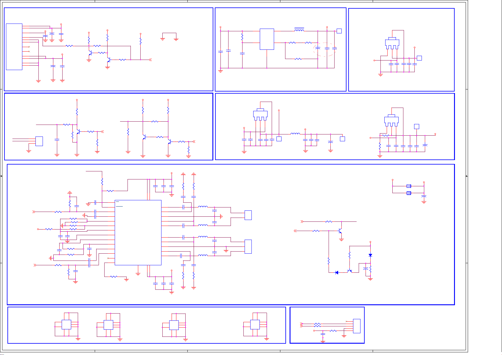
5
A
A
PM5V
standby
PM5V
12V912V
A
A
A
A
A
A
4
3
2
1
POWER & INVERTER CONTRAL
CON1 12pin/2.0MMCON1 12pin/2.0MM
1
2
3
5VSB
4
5
GND
6
GND
BL_ON/OFF
BL_PWM
GND
GND
7
8
10
11
12
D D
backlight
CON6-2.0mm
CON6-2.0mm
CON3
C C
BL-ADJUST
BL-ON/OFF
CON3
The power amplifier
4
AMP-AUOUTL0
B B
AMP_12V
4
AMP-AUOUTR0
C22
C22
470uF
470uF
1
2
3
+5V_Standby
+12V_NORMAL
BL-ADJUST
R262 10RR262 10R
+5V_Normal
C1
470uFC1470uF
470uFC7470uF
R274 1kR274 1k
C204
C204
1uF
1uF
R271 1kR271 1k
C7
2.2uFC92.2uF
C2
0.1uFC20.1uF
R194 100RR194 100R
C8
0.1uFC80.1uF
R61KR6
1K
R7
10K/NCR710K/NC
C9
R275
R275
100k
100k
R282 10kR282 10k
R281 10k/NCR281 10k/NC
R286 10kR286 10k
R287 10k/NCR287 10k/NC
C135
C135
10uF
10uF
R254 10kR254 10k
R273 10k/NCR273 10k/NC
R272
R272
100k
100k
R12KR1
2K
C194
C194
100nF
100nF
AV_R_OUT#
Q101
Q101
3904
3904
1
Q1
2 3
3904Q13904
C237
C237
330pF
330pF
AV_L_OUT#
C285 1uFC285 1uF
C286
C286
330pF
330pF
+5V_Standby
2 3
SHUTDOWN
C189 1uF/NCC189 1uF/NC
C288
C288
C289 1uFC289 1uF
C188
C188
1uF
1uF
C284 1uFC284 1uF
R2012kR201
2k
R8
4.7KR84.7K
R200
R200
H:OFF
L:ON
R199
R199
1
1uF
1uF
+5V_Standby
NC/0R
NC/0R
4.7k
4.7k
Q102
Q102
3904
3904
2 3
3
BRI_ADJ-PWM0
4.7k
4.7k
R12
R12
R2761KR276
1K
R285
R285
SD
LIN_P
LIN_N
GAIN0
GAIN1
AVCC
GVDD
PLMIT
RIN_N
RIN_P
R278 0RR278 0R
R197
R197
4.7k
4.7k
H:ON
L:OFF
1
R198 4.7kR198 4.7k
+3.3V_Standby
PWR-ON/OFF
+5V_Standby
R36
R36
4.7k
4.7k
PWR-ON/OFF
2
C3
0.1uFC30.1uF
C6
10uFC610uF
U1
SY8008BU1SY8008B
4
R65
R65
100K
100K
C16
C16
0.1uF
0.1uF
SW3VIN
R39
1
EN
R39
5
FB
GND
2
R1
100R
100R
R5 6.2KR5 6.2K
R2
R10 5.6KR10 5.6K
L1
12
CA1
CA1
100uF/16V
100uF/16V
3.3uHL13.3uH
Vout=0.6V*(1+R1/R2)
L17 22UHL17 22UH
L30 22UHL30 22UH
L32 22UHL32 22UH
L31 22UHL31 22UH
+3.3V_NORMAL
U4
U4
AP1084-3.3V
AP1084-3.3V
+5V_Normal
C18
C18
10UF
10UF
C283
C283
LOUT+
0.47UF
0.47UF
LOUT-
C287
C287
0.47UF
0.47UF
ROUT-
C281
C281
0.47UF
0.47UF
ROUT+
C282
C282
0.47UF
0.47UF
1
2
3
C23
C23
0.1u
0.1u
CON602CON602
2
1
CON601
CON601
GND
+
3Pin/2.0mm
3Pin/2.0mm
4
+3.3V_NORMAL
OUT
OUT
DJ
DJ
IN
IN
321
1
TP4NCTP4
NC
C24
C24
C19
C19
C20
C20
10UF
10UF
0.1u
0.1u
10UF
10UF
AMP-MUTE4
L12
L12
FB_100R
FB_100R
HP_MUTE_AMP
L:ON
H:MUTE
3.3V_Tun
C41
C41
10UF
10UF
R267 10kR267 10k
+5V_Normal+5V_Normal +5V_Normal
R21KR2
1K
BL-ON/OFF
R20
R20
10K/NC
10K/NC
Q2
3904Q23904
100k
100k
U18
U18
1
SD
2
FAULT
3
LINP
4
LINN
5
GAIN0
6
GAIN1
7
AVCC
8
AGND
9
GVDD
10
PLIMIT
11
RINN
12
RINP
13
NC
14
PBTL
TPA3110L
TPA3110L
GND-PAD
29
R3
4.7KR34.7K
R4
4.7K/NCR44.7K/NC
R11
26
25
24
23
22
21
20
19
18
17
C203
C203
100nF
100nF
C195
C195
100nF
100nF
Q3
2 3
3904Q33904
AMP_12V
OUTPL
OUTNL
OUTNR
OUTPR
AMP_12V
R11
4.7K
4.7K
1
C65
C65
10uF
10uF
C290 0.22UFC290 0.22UF
C278
C278
C279
C279
C280 0.22UFC280 0.22UF
C198
C198
10uF
10uF
R21
R21
4.7k
4.7k
R279
R279
10R/NC
10R/NC
C200
C200
330PF/NC
330PF/NC
0.22UF
0.22UF
0.22UF
0.22UF
C202
C202
330PF/NC
330PF/NC
R284
R284
10R/NC
10R/NC
VBL_CTRL
R280
R280
10R/NC
10R/NC
C201
C201
330PF/NC
330PF/NC
C199
C199
330PF/NC
330PF/NC
R277
R277
10R/NC
10R/NC
1
R9
2 3
4.7KR94.7K
C196
C196
1nF
1nF
28
BSPL
PVCCL27PVCCL
OUTPL
PGND
OUTNL
BSNL
BSNR
OUTNR
PGND
OUTPR
BSPR
PVCCR15PVCCR
16
C197
C197
1nF
1nF
10UF
10UF
C62
C62
VDDC
+
+
C42
C42
10UF
10UF
R268 0RR268 0R
1000mA Max
靠近
C4
0.1uFC40.1uF
470uF
470uF
R224
R224
10K
10K
D206 1N4148D206 1N4148
TP1NCTP1
1
NC
DC-DC
C5
10uFC510uF
C34
C34
1
1
TP6NCTP6
NC
SHUTDOWNHP_MUTE_AMP
Q28
Q28
3904
3904
2 3
R223
R223
10K
10K
1
C245
C245
Q207
Q207
100uF/16V
100uF/16V
23
3906
3906
+5V_Standby
+5V_Normal
AMP_12V
+3.3V_Standby
DJ
DJ
C10
C10
0.1u
0.1u
+1.8V_Standby
DDR
U5
U5
AP1117-ADJ/NC
AP1117-ADJ/NC
DJ
DJ
R19
R19
100R/NC
100R/NC
R230RR23
C27
C27
0R
10UF/NC
10UF/NC
D207
D207
1N4148
1N4148
R222
R222
100K
100K
4
OUT
OUT
IN
IN
321
C11
C11
10UF
10UF
4
OUT
OUT
IN
IN
321
C21
C21
0.1u
0.1u
0.1u/NC
0.1u/NC
+12V_NORMAL
U2
U2
AP1117-3.3
AP1117-3.3
C12
C12
10UF
10UF
C28
C28
L204
L204
L203
L203
+3.3V_Standby
C13
C13
10UF
10UF
C29
C29
10UF/NC
10UF/NC
0805_BEAD
0805_BEAD
0805_BEAD
0805_BEAD
TP2NCTP2
1
NC
C14
C14
0.1u
0.1u
TP3NCTP3
NC
1
C25
C25
10UF/NC
10UF/NC
CA5
CA5
AMP_12V
C215
C215
470uF
470uF
+
+
470uF/16V
470uF/16V
+1.8V_NORMAL
Screw holes
8
8
9
1
7
2
3
6
H1
4
5
PADH1PAD
5
8
9
1
7
2
3
6
H2
4
5
PADH2PAD
4
8
9
1
7
2
3
6
H3
4
5
PADH3PAD
3
9
1
7
2
3
6
H4
4
5
PADH4PAD
I2C
SDA
SCL
+3.3V_NORMAL
22R
22R
R13
R13
R14
R14
22R
22R
C15
C15
R150RR15
0.1u
0.1u
2
CON32
CON32
1
2
3
4
5
0R
CON5-2.0mm
CON5-2.0mm
56
Page 58
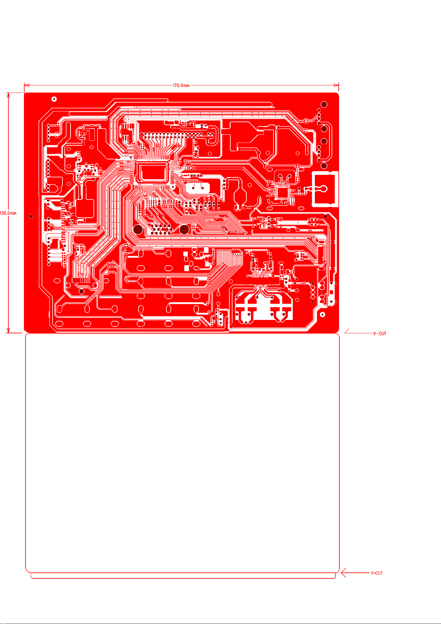
The main board screen printing diagram
57
Page 59
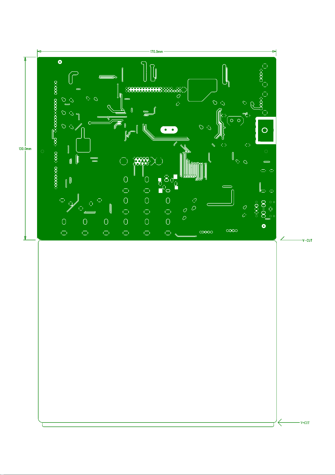
58
Page 60
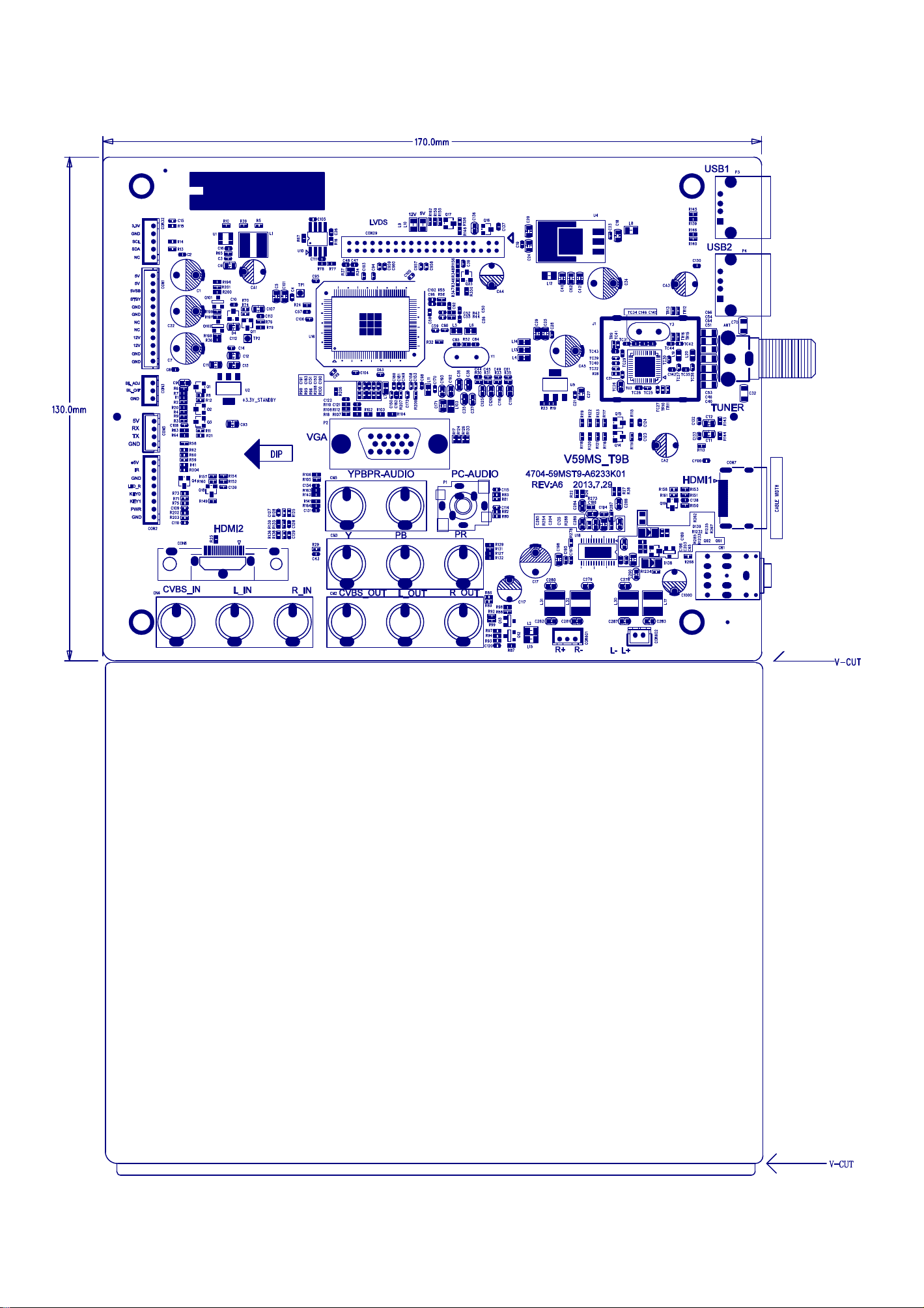
59
Page 61
60
Page 62
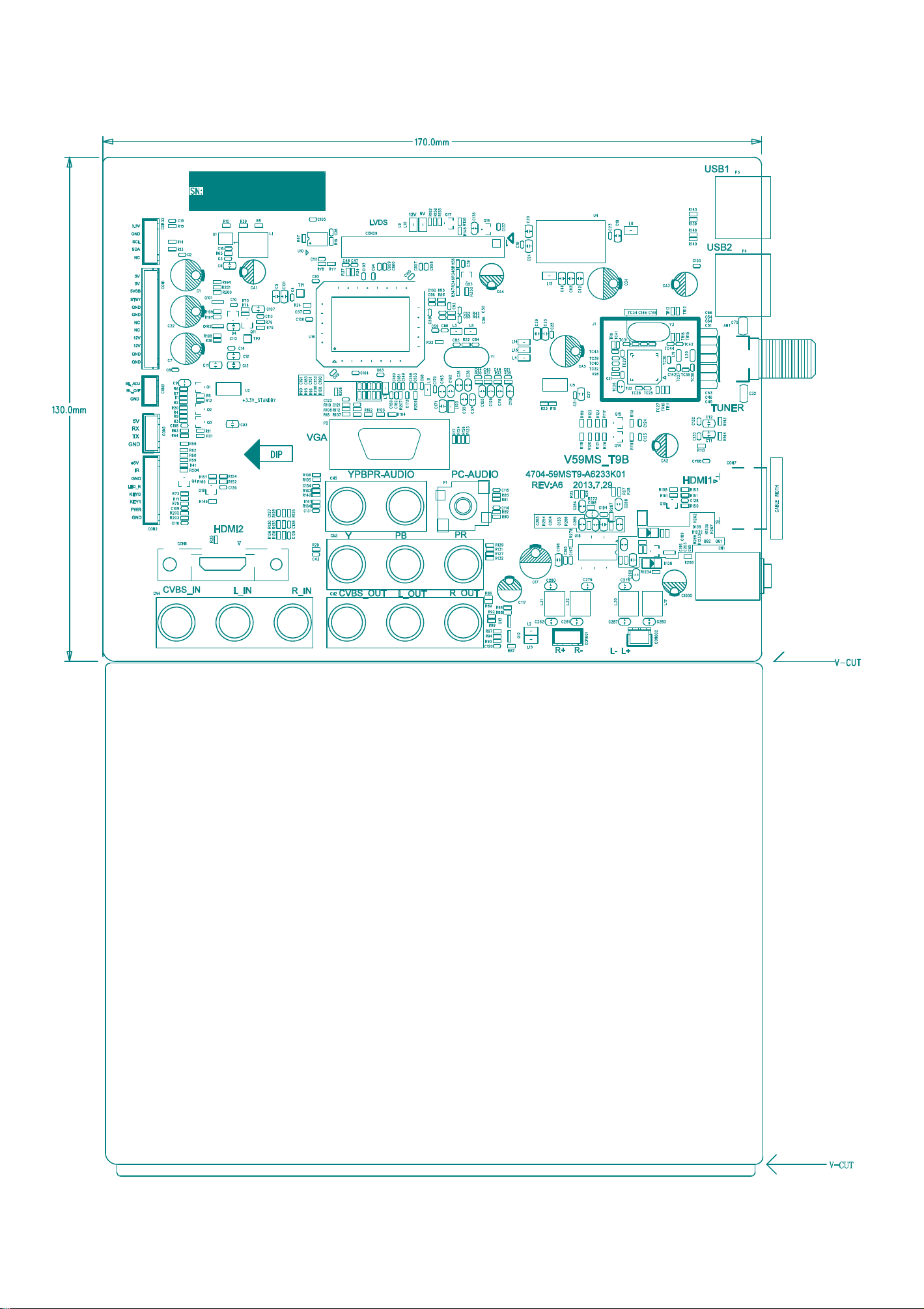
61
Page 63
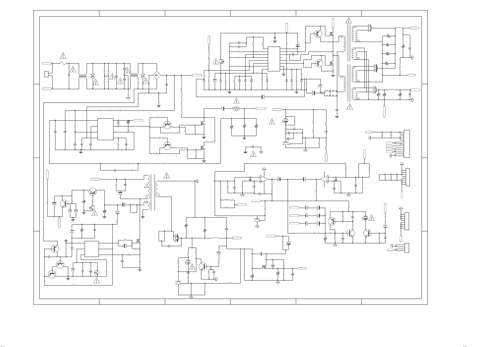
654321
R54
Q8
VC_PWM
C45
V_bus
D
F1
AC L
CON1
2
1
AC N
C
C25 C21
VC_PFC
B
D6
R81
R5
VC_PWM
R6
R7
Q1
C2
Q3
A
Q2
R2
R1
VR2
1
2
3
4
C24
C72
V_bus
Q10
R60
C32
UF1B
C4
C5
IC1
1 6
GND
GATE
2 5
FB
VCC
RI SENSE
3 4
R43
C6
C75
R3
R35
IC2
FB
Vcontrol
In
CS VM
C7
U1B
R11
R4
R34
Vcc
Drv
GND
R17
LB1
CX1
R36
C22
Q11
R61
ZD3A
ZD2
ZD1
R8
C3
ZD7
R9
1 2 3 4 5 6
CY1
LB2
CX2
CY2
R37
R33
C27
8
7
6
5
C26
C8
VC_PFC
C27A
C23
R38
R41
D4
D2
D1
R10
R14
D3
R40
R39
C9
R13
R12
QP1
R133
R15
R16
BD1
2
VR1
4 1
R52
R48
T1
2
3
4
7
6
R27
1K
3
C1
R44
R51
Q7
R47
Q6
R42
10
8
R28
LF1
LF2
LF3
D5
C12
R19
R18
U1A
3
U3
1
2
R62
R63
R64
V_in
C33
R50
R49
R46
R45
C13
R20
C11
R23
R24
R59
U2B
C35
D7
R69
R65
DF1
QF2
QF1
R91
R104
R105
R106
C14
Q4
R21
R25
C17
NC
L1
ZD3
R22
C10
R26
R73
C39
C40
R71
R74
R68
C36
C37 C38
R70
NTC1
2T
C29
28
C58
R103
C59
12V Is
U5
5V SB
R29
R72
1
Css
2
Fmax
3
Ctimer
4
RT
BO5Vcc
6
FB
7
DT
8
FF
R66
R67
C34
D8
LL4148
V_bus
C30
CY3
4
IC4A
2
1
3
8
C57
C56
5V SB
R92
3
1
2
12V
C20
NC
Q5
C15
3C
R79
IC3
16
Vboot
15
Mup
14
HB
13
NC
12
11
Mlow
10
PGnd
9
SF
C43
24V
U2A
3
U4
2
D17
R100
R145
R32
R31
C19
R30
C16
R80
R53
D10
C44
R109
C61
C62
1
24V
12V
D31
C42
R57
R56
Q9
R77
R78
C41
R76
R108
R112
5V
C18
D11
R75
D12
R117
C60
R115
R110
R111
D18
D14
ZD4
D16
ZD6
D15
ZD5
R107
5V
V_bus
T2
3
QP2
R55
6
QP3
R58
3
R82
R84
6
C46
4
7
8
R99
C55
R83 R85
R116
C63
R113
R114
12V
IC4B
6
5
C49
R98
T3
C31
R90
C50
C51
R88
R95
Q13
R94
R93
C53
Q12
C52
104/50V
D20
11
12
13
8
9
10
D21
11
12
13
D19
8
R101
UF1A
9
C64
10
12V
24 V Is
R102
R89
R96
Q14
C69
12 V Is
R86 R87
L3
24V
C66
C67
C68
L2
C65
R118
5V
5VSB
PS
5V
PS
R97
D13
C54
24V
C71
C70
R119
C48
CON4
1
2
3
4
5
6
7
8
9
10
11
12
13
CON2
R120 R121 R126 R123
24V
CON5
8
7
6
5
4
3
2
1
24V
CON3
1
2
3
4
D
24V Is
12V
C47
C
8
7
6
5
4
3
2
1
B
A
Power circuit diagram
62
Page 64
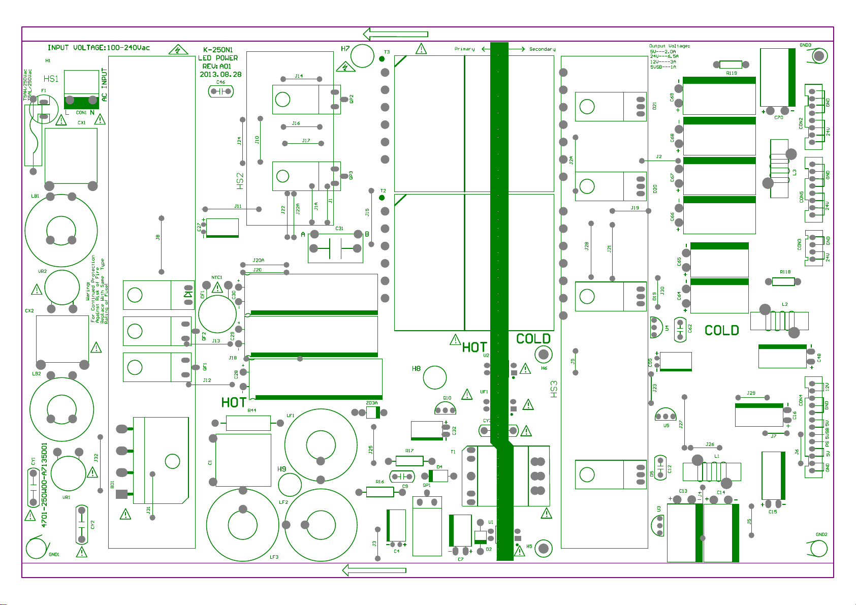
Power board printing diagram
63
Page 65
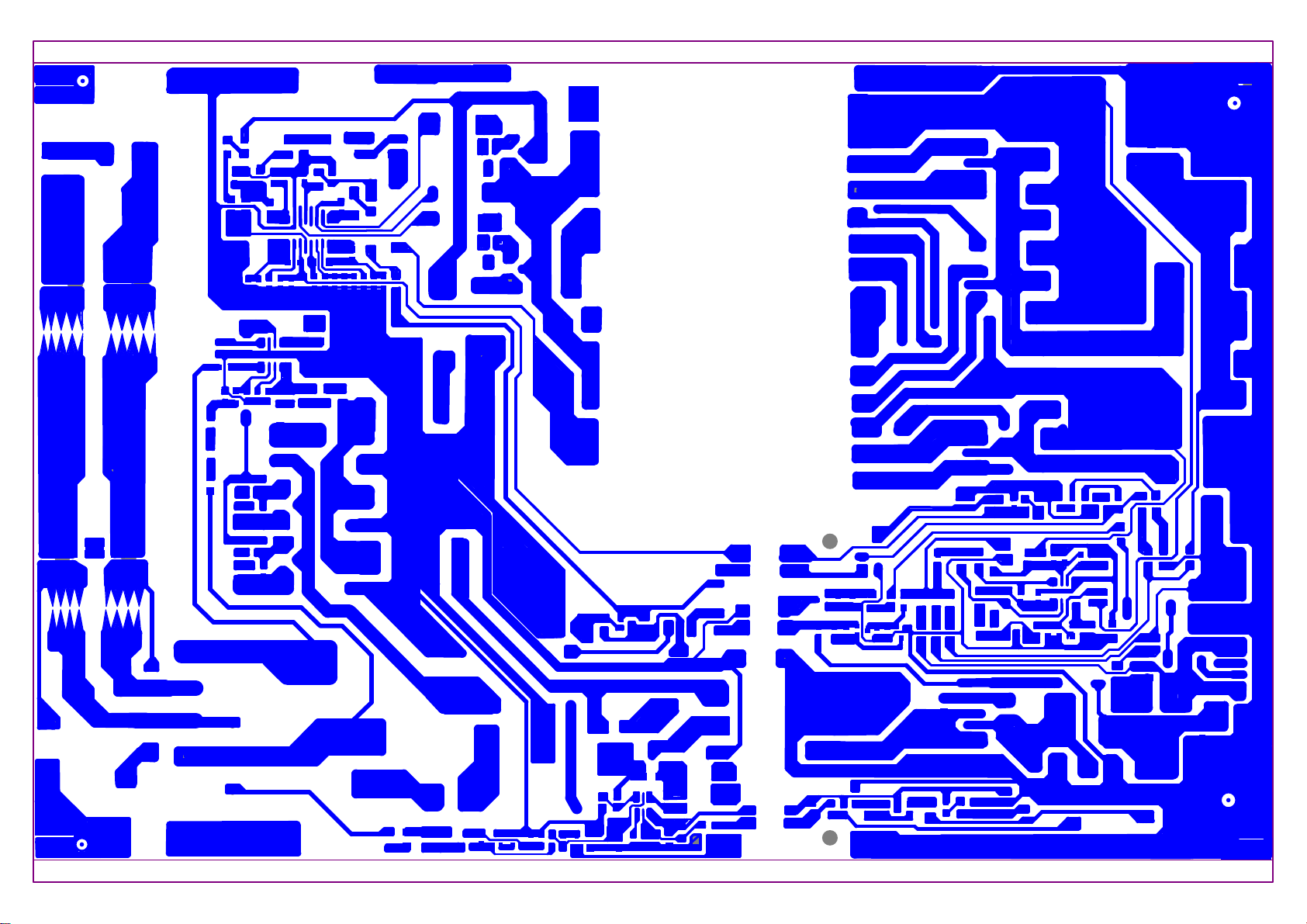
64
Page 66
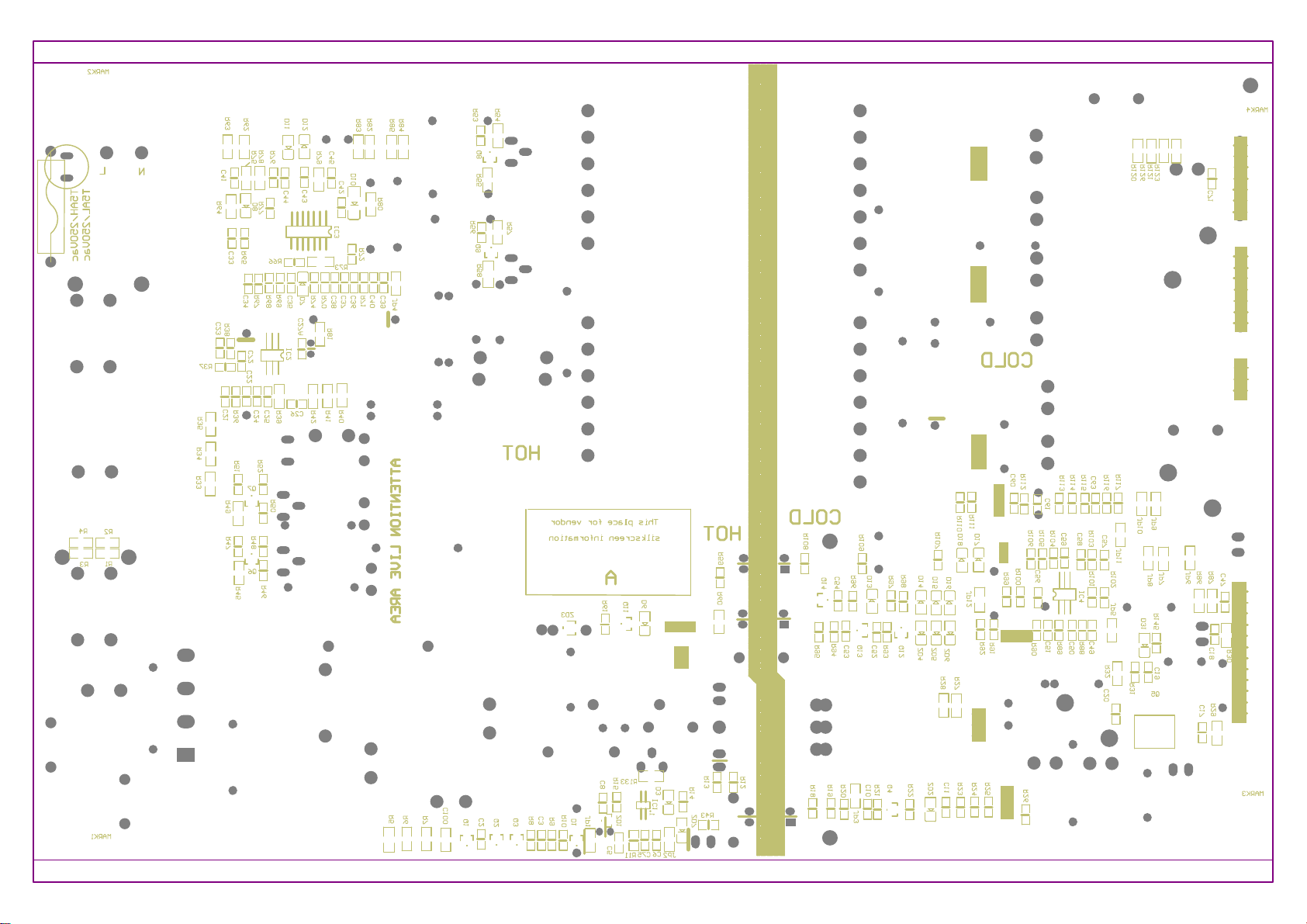
65
Page 67
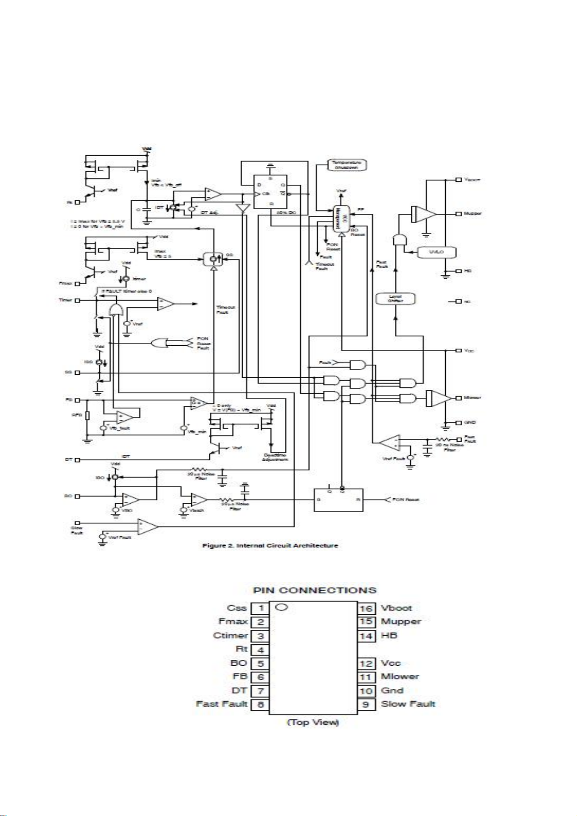
Main IC and pins internal block diagram
Main circuit LLC control
The internal block diagram
IC(NCP1396A)
Pins introduce
66
Page 68
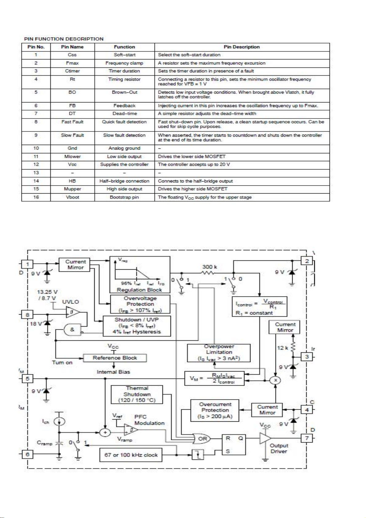
PFC
control
IC(NCP1396A)
The internal block diagram
67
Page 69
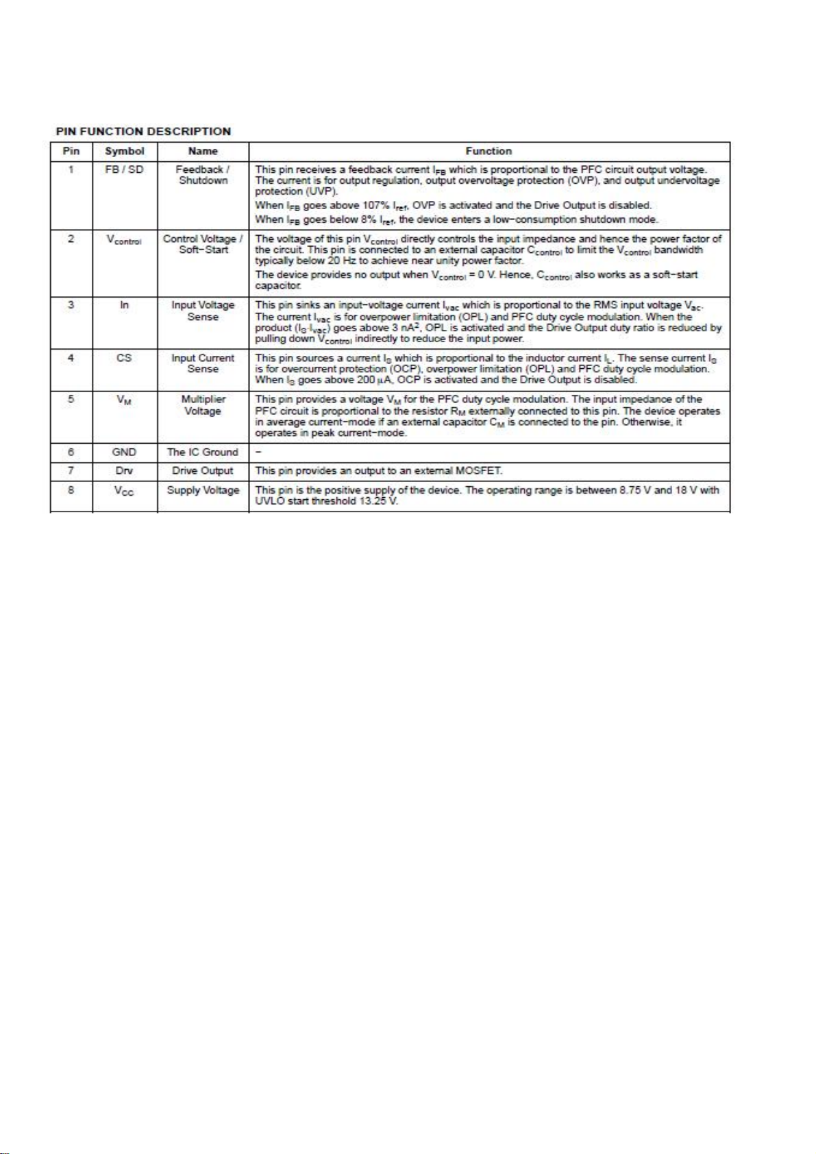
68
Page 70
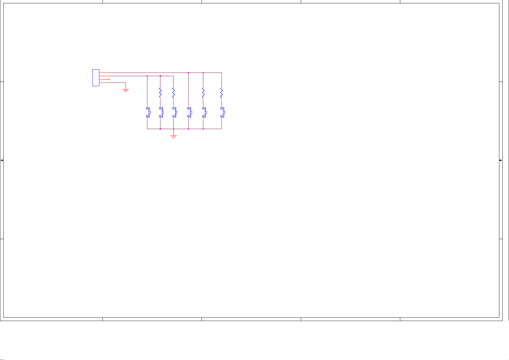
5
4
3
2
1
D D
C C
B B
key board circuit diagram
CN1
CN1
4
3
2
1
1X4P_1.25MM
1X4P_1.25MM
AD1
AD2
GND
SW03
SW03
VOL-
VOL-
R02
R02
2kΩ
2kΩ
VOL+
VOL+
SW02
SW02
R01
R01
6.8kΩ
6.8kΩ
MENU
MENU
SW01
SW01
CH+
CH+
SW04
SW04
R04
R04
2kΩ
2kΩ
SW05
SW05
CH-
CH-
R03
R03
6.8kΩ
6.8kΩ
SW06
SW06
SOURCE
SOURCE
A A
5
4
3
2
1
69
Page 71
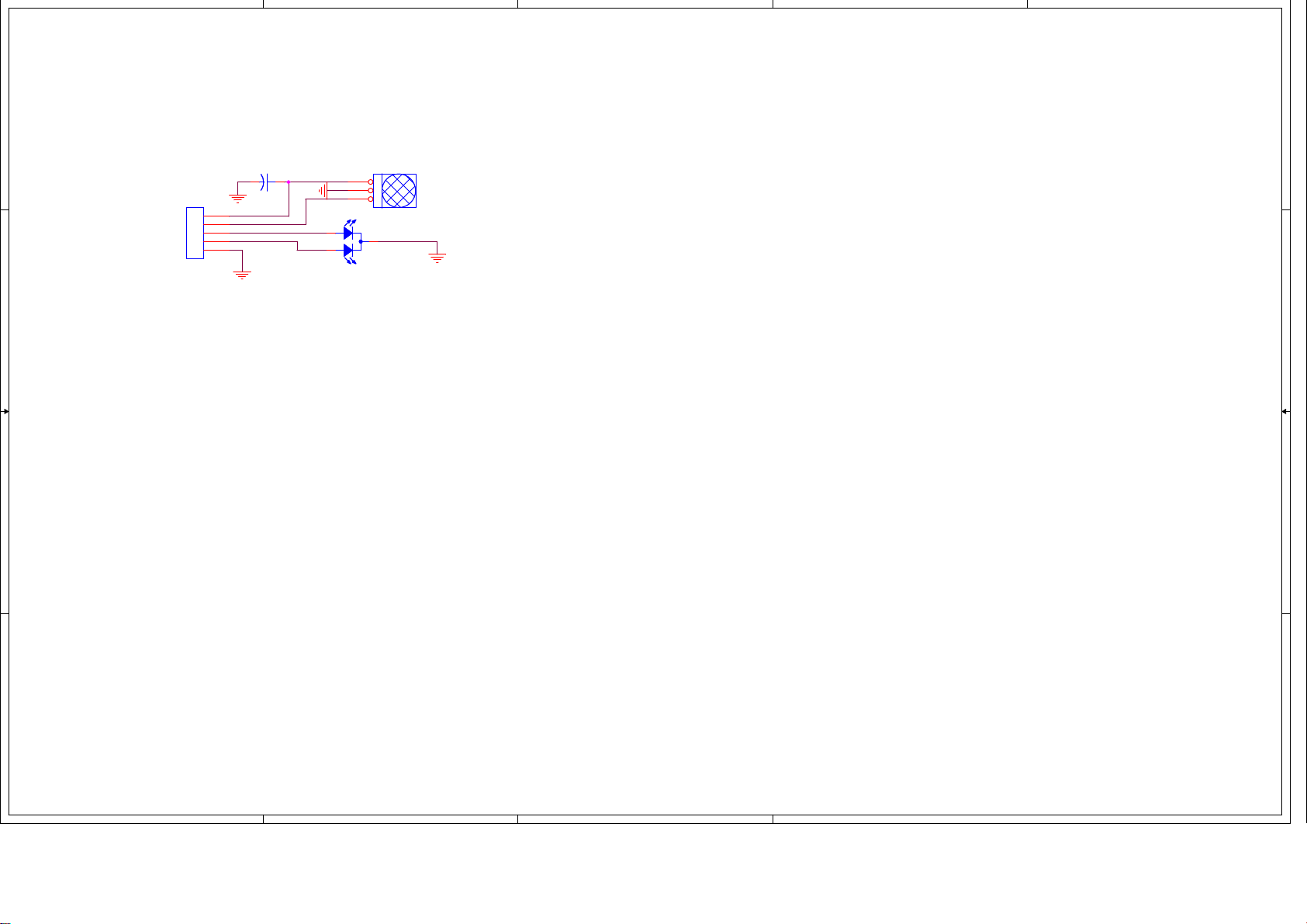
5
D D
4
3
2
1
The IR board circuit diagram
C1 22uF/16V
C1 22uF/16V
+
+
5P_2.0MM
5P_2.0MM
CON1
CON1
C C
IR_5V
5
IR
4
LED_RED
3
LED_BLUE
2
1
IC1 IRIC1 IR
3
2
1
LED1
LED1
RED/BULE LED
RED/BULE LED
B B
A
5
4
3
2
70
Page 72
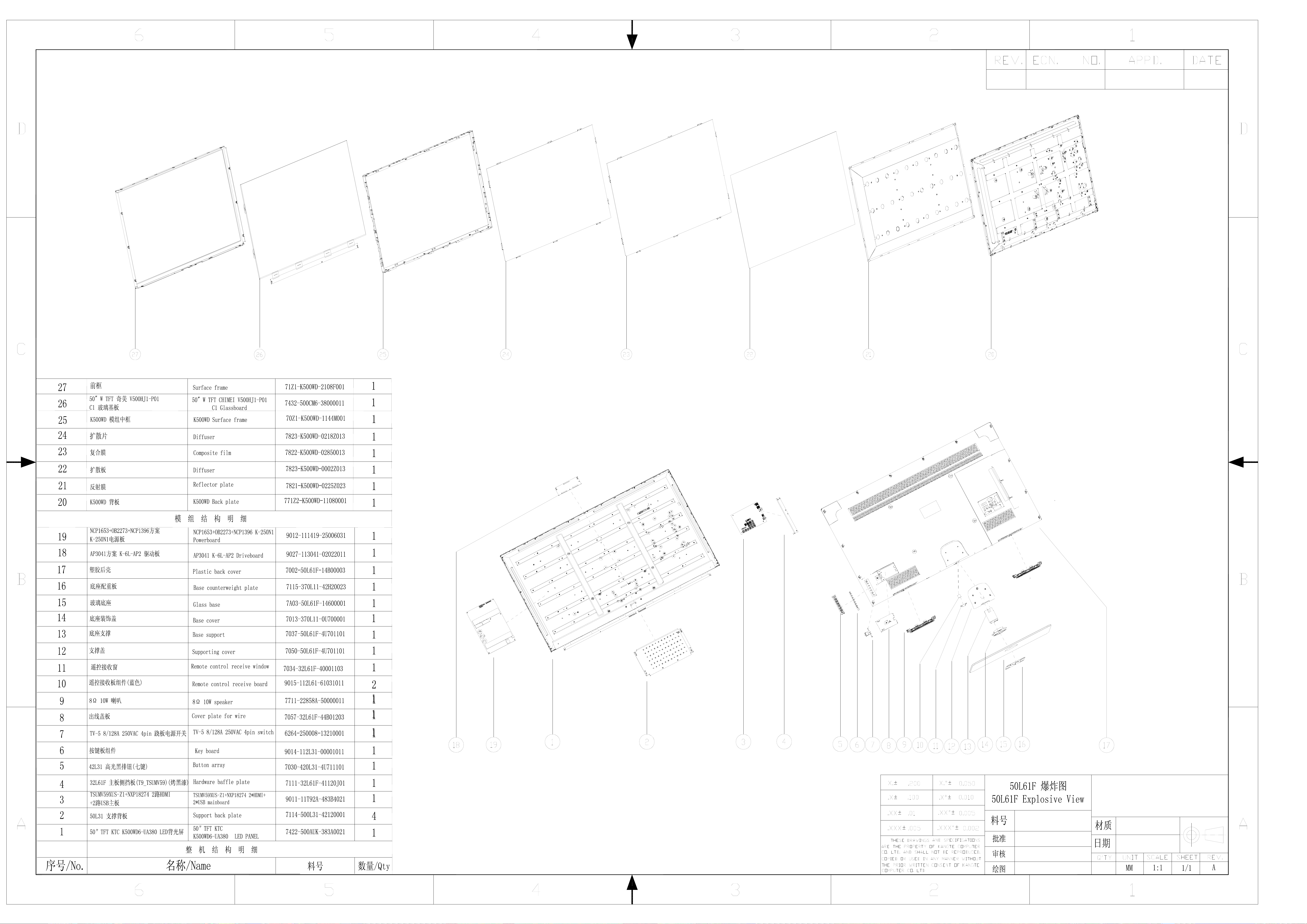
Mechanical Overview
71
Page 73
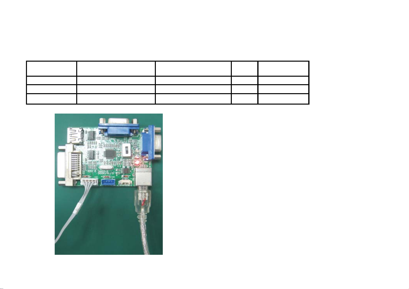
service training material list
Old P/N P/N Description Qty Unit price
502-0081-00001 USB burn tool 1 42.3
512-0113-USB15 5102-Z00USB-1R5M0021 USB Using reflection line 1 0.95
603-4502-05111G 6149-4500C4-05111201 connecting wire 1 0.25
502-0081-00001
603-4502-05111G
($)
512-0113-USB15
72
Page 74
SPARE PARTS LIST
Customer model:50PFL3108/98
Factory model:50L61F-H-CN
Chassis:T9 board TV 12V TSUMV59XUS+NXP18274 main board
Module/Panel Specification:50″TFT KTC K500WD6-UA380 LED PANEL
No Spare parts number Spare Parts Name in English Spare Parts Name in Chinese Qty Price($)
1
6110-150022-06211701 Power Cord
电源线
2
6149-510063-51781203 LVDS Connection Wire LVDS
线
3
6149-750015-13111201 Connection Wire for power board
主板到电源板线
1
1
1
Not
reflected in
the
Mechanical
Overview
Not
reflected in
the
Mechanical
Overview
Not
reflected in
the
Mechanical
Overview
4
5
6
7
8
9
10
6149-720035-14112303 Connection Wire For key board
9011-11T92A-483B6231 Main Board
9012-111419-25007011 Power Board
9015-112L61-61031021 Remote control receive board
9014-112L31-00001011 Keyboard
7002-50L61F-14V00003 Back Cover
7A03-50L61F-14600001 Base
主板到按键板线
主板
电源板
遥控接收板
按键板
后壳
底座
73
Not
reflected in
the
Mechanical
1
13
119
110
16
117
115
Overview
Page 75
11
12
13
14
15
16
17
18
7311-50L61F-128FLP11 User manual
7422-500AUK-383A0031-
7601-31A062-0144FL P1 Remote control
7711-22858A-50000011 Speaker
7211-50L61F-102FLP11 Carton
7201-50L61F-40211301 Cushion
7030-420L31-4U7111 01 Menu button
7057-32L61F-44J01103 Power switch
LED Panel LED
说明书
屏
遥控器
喇叭
纸箱
保丽龙
排钮
电源开关
Not
reflected in
the
Mechanical
1
11
1
29
1
1
15
17
Overview
Not
reflected in
the
Mechanical
Overview
Not
reflected in
the
Mechanical
Overview
Not
reflected in
the
Mechanical
Overview
74
Page 76
key components list
物料编号(Part number) 描述(中、英文)Description 用量Qty 单位Unit
6110-150022-06211701 1.5m power cord
1.5m 电源线
6149-110334-08112301 1100/600mm 8pin,5pin,4pin three-terminal wire
1100/600mm 8pin,5pin,4pin 三端子线材
6149-170056-03301111 170mm 2pin wire
170mm 2pin 线材
6149-300045-02101201 300mm 2Pin speaker wire
300mm 2Pin 喇叭线
6149-510063-51781203 510mm 51pin,40pin LVDS two-terminal wire
510mm 51pin,40pin LVDS 双端子线材
6149-720035-14112303 720|550mm 14Pin,8Pin,3Pin Three-terminal wire
720|550mm 14Pin,8Pin,3Pin 三端子线材
6149-750015-13111201 750mm 13pin,12pin Two terminal wire
750mm 13pin,12pin 二端子线材
6149-900045-03101101 900mm 3Pin speaker wire
900mm 3Pin 喇叭线
6251-2502R5-12230011 250V AC power socket
250V AC电源插座
7002-50L61F-14V00003 Plastic back cover
塑胶后壳
7030-420L31-4U711101 Button array
排扭
7034-50L61F-446FLP13 Remote control receive window
遥控接收窗
7037-50L61F-4U701101 Base support
底座支撑
7050-50L61F-4U701101 Supporting cover
支撑盖
7057-32L61F-44J01103 Cover plate for wire
出线盖板
7097-420L31-44J11103 Power socket stand
电源插座盖
70E8-000000-44401101 (Φ14*10) insulation sleeve
(Φ14*10) 绝缘套
7111-32L61F-41120J01 Hardware baffle plate
五金挡板
7114-500L31-42120001 Support back plate
支撑背板
7115-50L61F-42120001 Base counterweight plate
底座配重板
7201-50L61F-40211301 Styrofoam
保利龙
7211-50L61F-102FLP11 Carton
整机包装箱
7231-080050-00012211 Flat pockets
平口袋
7231-125850-00011111 Flat pockets
平口袋
7231-550320-00013211 Flat pockets
1.00
1.00
1.00
1.00
1.00
1.00
1.00
1.00
1.00
1.00
1.00
1.00
1.00
1.00
1.00
1.00
1.00
1.00
1.00
1.00
1.00
1.00
1.00
1.00
1.00
PCS
PCS
PCS
PCS
PCS
PCS
PCS
PCS
PCS
PCS
PCS
PCS
PCS
PCS
PCS
PCS
PCS
PCS
PCS
PCS
PCS
PCS
PCS
PCS
PCS
75
Page 77
平口袋
7233-290211-00014211 Zip-lock bag
骨袋
7311-50L61F-128FLP11 Instruction
说明书
7314-50L61F-128FLP11 Instruction
说明书
7371-50L61F-02FLP211 Rear nameplate
后铭牌
7372-32L61F-22010231 Interface adhesive film
接口贴膜
7372-32L61F-72020263 Interface adhesive film
接口贴膜
7372-32L61F-Z2000221 Interface adhesive film
接口贴膜
7373-000000-10000011 Paster
贴纸
7373-000000-20000081 Paster
贴纸
7374-032006-0101FLP1 Logo
精雕铝牌
7422-500AUK-383A0031-F 50″TFT KTC K500WD6-UA380 LED PANEL
50″TFT KTC K500WD6-UA380 LED背光屏
7601-31A062-0144FLP1 Remote control
遥控器
7711-22858A-50000011 8Ω 10W speaker
8Ω 10W 喇叭
7911-211R50-00000031 1.5V Battery
1.5V 电池
7912-313010-01501011 Black pad/adhesive tape
黑色胶垫/胶布
7912-513190-0250R513 Black pad/adhesive tape
黑色胶垫/胶布
7912-513190-0250R523 Black pad/adhesive tape
黑色胶垫/胶布
7912-C22030-0150R113 Black pad/adhesive tape
黑色胶垫/胶布
7A03-50L61F-14600001 Glass base
玻璃底座
7B11-0302F0-00102111 Φ3×2.5×6mm Screw
Φ3×2.5×6mm 螺钉
7B11-030616-00105111 Φ3×6mm Screw
Φ3×6mm 螺钉
7B11-030696-00101111 Φ3×6mm screw
Φ3×6mm 螺钉
7B11-0306A4-00101111 Φ3×6mm Screw
Φ3×6mm 螺钉
7B11-0306A6-00105111 Ф3×6mm Screw
Ф3×6mm 螺钉
7B11-0306D4-30102111 Φ3×6mm Screw
Φ3×6mm 螺钉
7B11-0307C2-50102111 M3×7mm Screw
M3×7mm 螺钉
1.00
1.00
1.00
1.00
1.00
1.00
1.00
1.00
1.00
1.00
1.00
1.00
2.00
2.00
4.00
2.00
1.00
1.00
1.00
4.00
2.00
1.00
2.00
17.00
2.00
12.00
PCS
PCS
PCS
PCS
PCS
PCS
PCS
PCS
PCS
PCS
PCS
PCS
PCS
PCS
PCS
PCS
PCS
PCS
PCS
PCS
PCS
PCS
PCS
PCS
PCS
PCS
76
Page 78
7B11-031013-00105111 Ф3×10mm Screw
Ф3×10mm 螺钉
7B11-0310D3-30101111 Ф3×10mm Screw
Ф3×10mm 螺钉
7B11-0406D6-20101111 Φ4×6mm Screw
Φ4×6mm 螺钉
7B11-041082-30105113 Φ4×10mm Screw
Φ4×10mm 螺钉
7B11-0415D3-30101111 Φ4×15mm Screw
Φ4×15mm 螺钉
7B11-041696-20105111 Ф4×16mm Screw
Ф4×16mm 螺钉
9011-11T92A-483B6231 TSUMV59XUS(Dobly,No Rmvb)+NXP18274 2*HDMI+2*USB mainboard
TSUMV59XUS(带杜比,不带Rmvb)+NXP18274 2路HDMI+2路USB主板
9012-111419-25007011 NCP1653+OB2273+NCP1396 K-250N1 Powerboard
NCP1653+OB2273+NCP1396方案 K-250N1电源板
9014-112L31-00001011 Key board
按键板组件
9015-112L61-61031021 Remote control receive board
遥控接收板组件(蓝色)
9027-113041-02022011 AP3041 K-6L-AP2 Driveboard
AP3041方案 K-6L-AP2 驱动板
7.00
2.00
4.00
4.00
4.00
4.00
1.00
1.00
1.00
1.00
1.00
PCS
PCS
PCS
PCS
PCS
PCS
PCS
PCS
PCS
PCS
PCS
77
 Loading...