

Page 1

Field install guide
Philips Advance 503441
This installation guide is only valid for the following Philips EvoKit models:
EvoKit 2x4 P 36L xxW 835 2 0-10 7 G2
2x2 P 23L 830 1 Mk10
2x4 P 32L 835 2 0-10
Emergency LED driver for EvoKit G2
36L 840 2 STEP
42L 5 Mk10
52L
20140604
Page 2
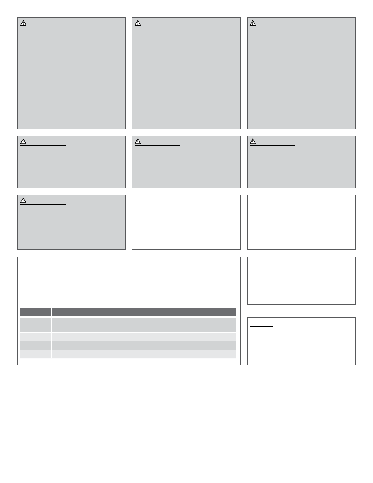
WAR N ING
FAILURE TO FOLLOW THESE
INSTRUCTIONS AND WARNINGS MAY
RESULT IN SERIOUS INJURY OR
SIGNIFICANT PROPERTY DAMAGE.
For your protection, carefully read
these warnings and instructions in their
entirety before installing or maintaining
this equipment. These instructions do
not attempt to cover all installation and
maintenance situations. If you do not
understand these instructions or if additional
information is required, contact your
local Philips representative. Retain these
instructions for maintenance reference.
WAR N ING
RISK OF FIRE OR ELECTRIC SHOCK
The Emergency LED driver must be installed
and maintained by a professional electrician
in accordance with the applicable federal,
state and local laws, regulations and electrical
codes, and the installation instructions
provided in this document. This professional
should be familiar with the construction and
operation of this product and any hazards
involved. If not qualified, do not attempt
installation. Contact a qualified electrician.
WAR N ING
RISK OF FIRE, ELECTRIC SHOCK OR
PERSONAL INJURY
Do not install in a damaged fixture.
Before installation, turn power off.
WAR N ING
RISK OF FIRE OR ELECTRIC SHOCK
To prevent wiring damage or abrasion, do
not expose wiring to edges of sheet metal or
other sharp objects.
WAR N ING
RISK OF FIRE OR ELECTRIC SHOCK
Luminaire wiring and electrical parts may be
damaged when drilling for installation of LED
retrofit kit. Check for enclosed wiring and
components.
WAR N ING
RISK OF PERSONAL INJURY
This equipment may have sharp edges.
Wear gloves to prevent cuts or abrasions
when removing from carton, handling and
maintaining this equipment.
Caution
This kit is designed for permanent
installation in ordinary (Non-Hazardous)
locations in accordance with the National
Electrical Code and all applicable local codes.
Do not use in areas of limited ventilation or
in high ambient enclosures.
Notice
Do not use abrasive materials, glass cleaners or other solvents on cover plate or lens. To clean
the faceplate, use a mild soap solution.
Do not expose the product to substances and /or materials containing sulphur, chlorine or
other halogen compounds and to chemicals mentioned in below table.
Category Chemical Name
Solvents Toluene, xylene, benzene, chloromethane, chloroform, ethyl acetate, butyl
acetate, acetone, MEK, MIBK
Acid HCl, H
Alkali KOH, NaOH, LiOH, Ca(OH)
Oil Diesel oil, petroleum, hydro carbons
2SO4
, HNO
3
2
WAR N ING
RISK OF PERSONAL INJURY
Ensure all warning and cautionary markings
given in the Philips Advance 503441
installation instructions are heeded.
Caution
Do not make or alter any open holes in an
enclosure of wiring or electrical components
during kit installation except if specifically
mentioned in these installation guide.
Notice
Ensure an un-switched hot circuit is available
to the fixture. This is required for proper
emergency fixture operation.
Notice
Handle components with care. Do not drop,
slide or scratch any of the components to
prevent visual damage to the product, loss of
functionality or difficulties during installation.
220140604
Page 3
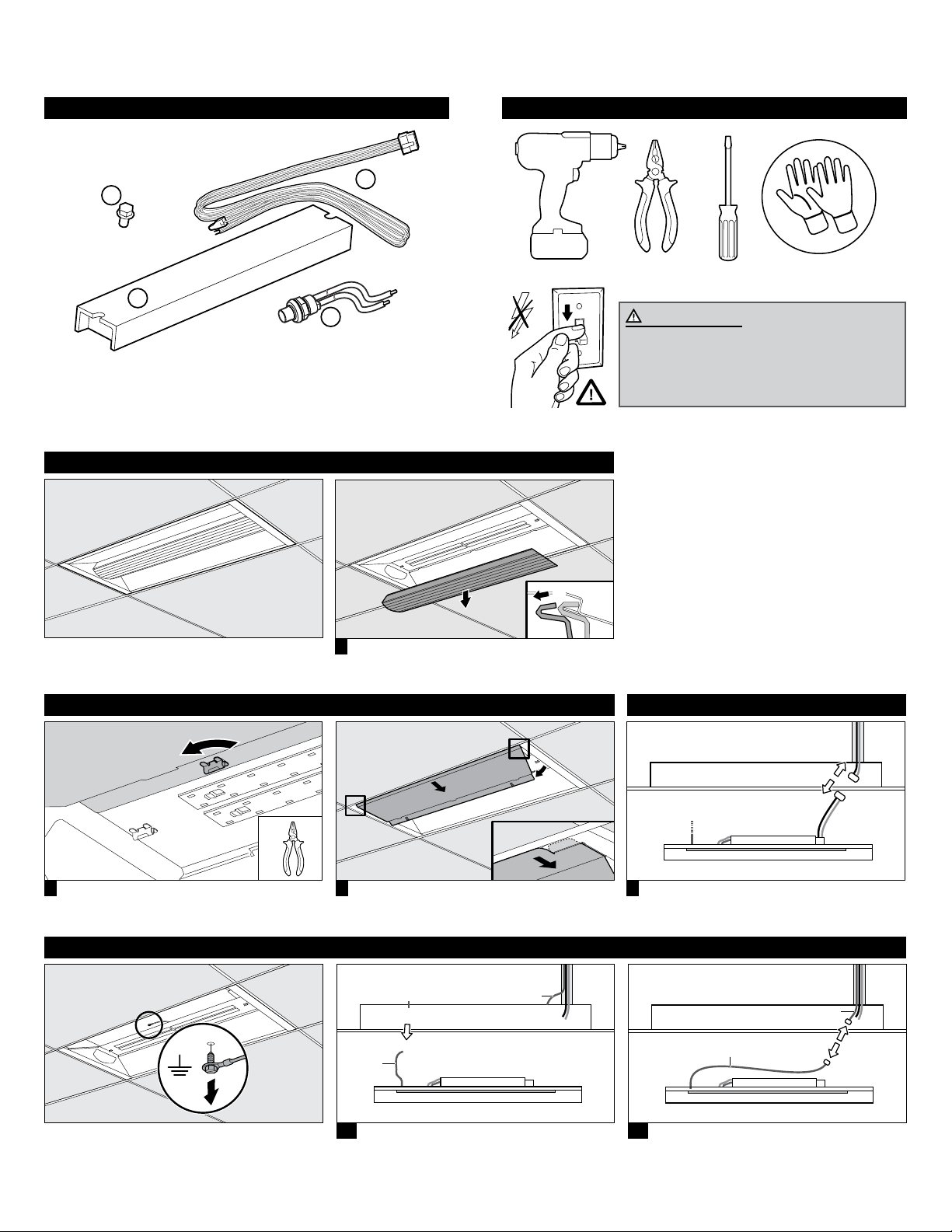
Field install Philips Advance 503441 Emergency LED driver
Set contains
2x
W
X
W Screw (2x)
X Emergency LED driver
Remove Diuser
Z
Y
Y Test switch
Z Wiring harnass
Tools required
WAR N ING
RISK OF FIRE, ELECTRIC SHOCK
OR PERSONAL INJURY
Before installation, turn power off.
2
1 Remove Diffuser by pressing one side of the
Diffuser.
1
Remove Closing Panel Mains disconnection
o
90
2
3 Lower the Closing Panel and slide it out. 2 Turn each fastener 90 degrees.
1
2
4 Disconnect mains.
Ground disconnection (Situation 1 - 2)
ground
ground
ground
5a Situation 1 Grounding:
Unscrew grounding cable.
ground
5b Situation 2 Grounding:
Disconnect the ground lead from conduit.
320140604
Page 4
red/white
Remove LED Panel
ATTENTION
ESD SENSITIVE
o
90
DO NOT
TOUCH LED
Notice
Do not touch the LEDs with hands or
1
2
2
tooling! Touching LEDs can lead to failure of
the product.
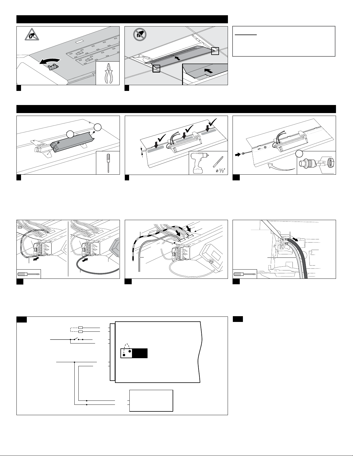
6 Turn each fastener 90 degrees.
7 Lower LED panel and slide it out.
Installation Philips Advance 503441 Emergency LED driver (X)
2x
W
X
15 mm
8 Secure 503441(X) to the back side of LED Panel
using t wo screws (W ).
9 Drill 1/2” hole in the LED Panel for installation of
LED/test switch on indicated area.
yellow /
black
red/white
max.
blue/white
Y
violet
brown
10 Install the test switch (Y) by feeding the violet
and brown wires through this 1/2” hole and hand
tighten the plastic nut included with the test
switch/LED combo.
Add connect from test switch to wiring harnass
(Z) (violet - violet, brown - brown).
black
503441
blue
11 Disconnect the red/white single wire from the
E
voKit driver. Replace it with the blue output
wire from the 503441 (Z). Place a wire nut over
the original red/white wire for proper isolation.
14a
CONVERTER
CONNECTOR
HOT
COMMON WHITE
WALL SWITCH
RED
RED
WHT/RED
BLACK
WHT/BLK
yellow
12 Connect the yellow output wire from the
03441 to the EvoKit red/white wire connection
5
block and the yellow/black output wire from the
503441 (Z) to the EvoKit blue/white wire
connection block.
JUMPER
WIRE
Emergency
LED
Driver
LOAD
SELECT
BLACK
WHITE
AC DRIVER
white
13 Disconnect black wire and insert white/black
wire (Z) in the EvoKit driver.
14a Connect WHT/RED, BLACK and WHITE (2x)
wires (Z) as p
Connect the 503441red to red as indicated in
schematic (Z).
er the 503441 wiring diagram.
420140604
Page 5
14b
CONVERTER
CONNECTOR
HOT
VIOLET
BROWN
COMMON WHITE
RED
RED
BLACK
VIOLET (+)
BROWN (-)
WHT/RED
WHT/BLK
BLUE
YEL/BLK
YELLOW
JUMPER
WIRE
LOAD
SELECT
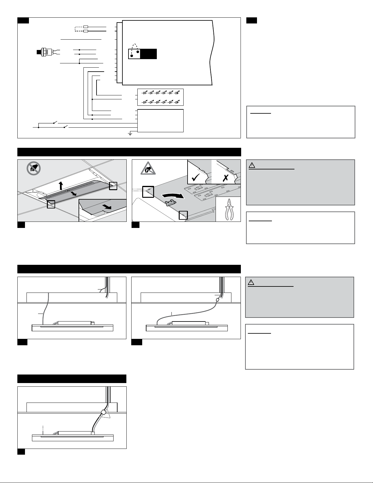
14b Emergency LED driver wiring in combination
with STEP version.
Emergency
LED
Driver
AC DRIVER (-)
AC DRIVER (+)
HOT
Installation LED Panel
DO NOT
TOUCH LED
2
1
1
15 Install LED panel in between trof fer and T-grid,
making sure the tabs at each corner of the LED
panel slide into the respective slots on the side
panel.
Ground connection (Situation 1 - 2)
LED (+)
LED (-)
WHITE
ESD SENSITIVE
LED LOAD
AC DRIVER
Live 1
Live 2
ATTENTION
90
o
16 Push LED panel upward into position so that the
tabs sits above the side panels (this may require
a push up on the tabs while pushing outward
on the side panels). Fixate panels and establish
ground by turning each fastener 90 degrees.
Notice
For the EvoKit, do not connect the jumper
wire / load select (yellow/red) on 503441.
WAR N ING
RISK OF PERSONAL INJURY
While installing the LED panel and Closing
Panel, make sure the electrical wiring is not
clamped between panels.
Notice
Do not touch the LEDs with hands or
tooling! Touching LEDs can lead to failure of
the product.
ground
ground
17a Situation 1 Grounding:
Screw grounding cable from Led Panel to
original troffer if host fixture ground connection
is made trough host f ixture.
Mains connection
mains
18 Connect mains and hide connected wires behind
LED Panel.
ground
ground
17b Situation 2 Grounding:
Connect to the incoming ground lead from
conduit.
WAR N ING
RISK OF PERSONAL INJURY
Proper grounding of EvoKit metal parts is
required to ensure personal safety.
Notice
Make new electrical connections to mains
by employing applicable connectors in
accordance with the applicable federal, state
and local laws, regulations and electrical
codes.
520140604
Page 6
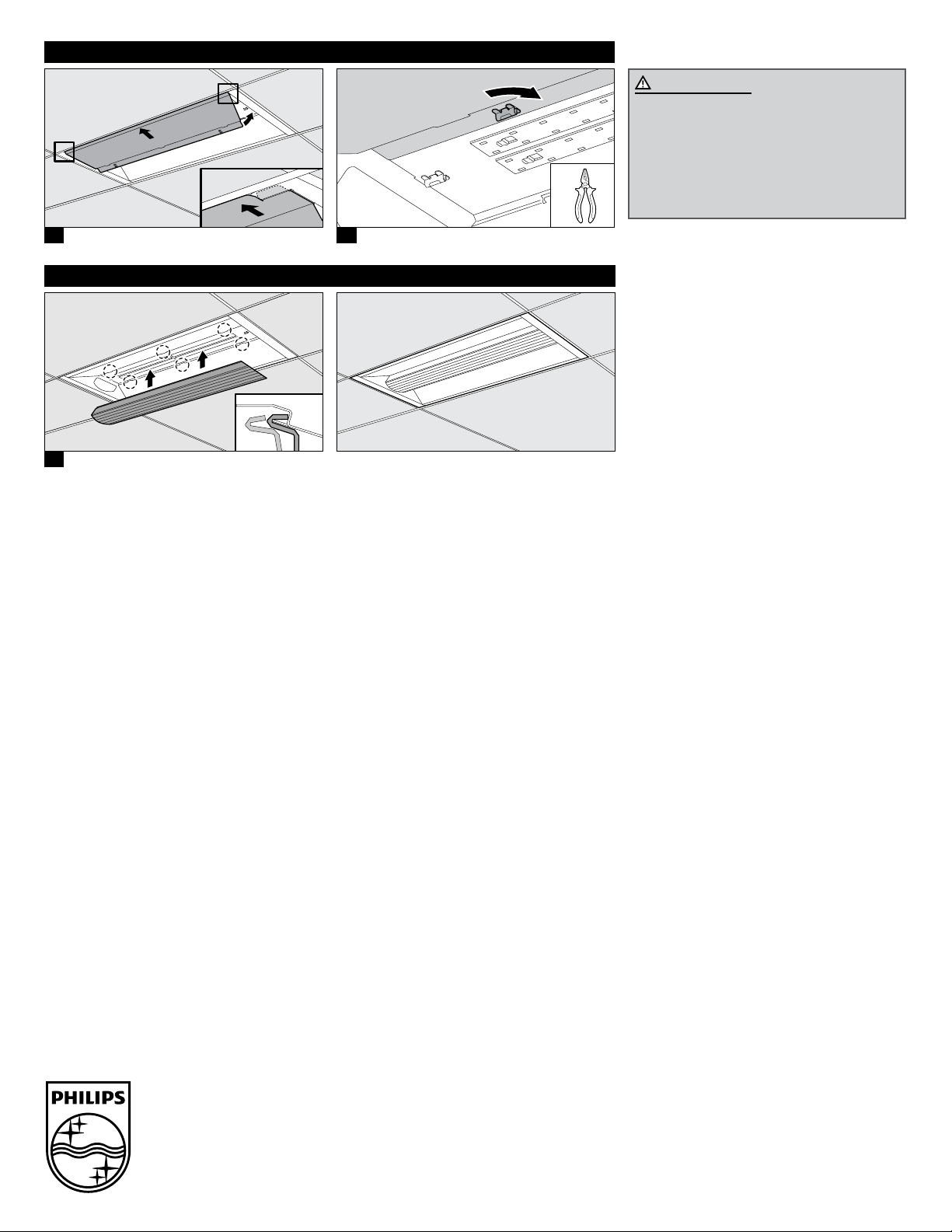
Installation Closing Panel
2
1
1
19 Install Closing Panel in-between troffer and
T-g r id.
Installation Diuser
21 Slide Dif fuser under the tabs on one side from
either Panel and press diffuser over the tabs on
opposite panel.
o
90
20 Fixate panels and establish ground by turning
each fastener 90 degrees.
WAR N ING
RISK OF FIRE OR ELECTRIC SHOCK
While installing the LED panel and Closing
Panel, make sure the electrical wiring is not
clamped between panels.
© 2014 Philips Lighting Company.
A Division of Philips Electronics North
America Corporation.
All rights reserved.
Printed in USA 9
www.philips.com
20140604
/14
Philips Lighting Company
200 Franklin Square Drive
Somerset, NJ 08873
1-800-555-0050
Philips Lighting
281 Hilmont Road
Markham, Ontario
Canada, L6C 253
1-800-555-0050
A Division of Philips Electronics Ltd.
620140604
 Loading...