

Page 1
For OS Version 1.04 and Up
Page 2

Philips Strand Lighting Offices
The material in this manual is for information purposes only and is subject to change without notice. Philips Strand
Lighting assumes no responsibility for any errors or omissions which may appear in this manual. For comments and
suggestions regarding corrections and/or updates to this manual, please contact your nearest Philips Strand Lighting
office.
El contenido de este manual es solamente para información y está sujeto a cambios sin previo aviso. Philips Strand
Lighting no asume responsabilidad por errores o omisiones que puedan aparecer. Cualquier comentario, sugerencia
o corrección con respecto a este manual, favor de dirijirlo a la oficina de Philips Strand Lighting más cercana.
Der Inhalt dieses Handbuches ist nur für Informationszwecke gedacht, Aenderungen sind vorbehalten. Philips
Strand Lighting uebernimmt keine Verantwortung für Fehler oder Irrtuemer, die in diesem Handbuch auftreten. Für
Bemerkungen und Verbesserungsvorschlaege oder Vorschlaege in Bezug auf Korrekturen und/oder
Aktualisierungen in diesem Handbuch, moechten wir Sie bitten, Kontakt mit der naechsten Philips Strand LightingNiederlassung aufzunehmen.
Le matériel décrit dans ce manuel est pour information seulement et est sujet à changements sans préavis. La
compagnie Philips Strand Lighting n'assume aucune responsibilité sur toute erreur ou ommission inscrite dans ce
manuel. Pour tous commentaires ou suggestions concernant des corrections et/ou les mises à jour de ce manuel,
veuillez s'il vous plait contacter le bureau de Philips Strand Lighting le plus proche.
Note: Information contained in this document may not be duplicated in full or in part by any person without prior written
approval of Philips Strand Lighting. Its sole purpose is to provide the user with conceptual information on the equipment
mentioned. The use of this document for all other purposes is specifically prohibited.
Document Number: STR-65354 A
Version as of: 15 June 2015
500ML Lighting Control Console QuickStart Guide
©2014 - 2015 Philips Group. All rights reserved.
Philips Strand Lighting - Dallas
10911 Petal Street
Dallas, TX 75238
Tel: +1 214-647-7880
Fax: +1 214-647-8030
Philips Strand Lighting - Auckland
19-21 Kawana Street
Northcote, Auckland 0627
New Zealand
Tel: +64 9 481 0100
Fax: +64 9 481 0101
Philips Strand Lighting - Asia
Unit C, 14/F, Roxy Industrial Centre
No. 41-49 Kwai Cheong Road
Kwai Chung, N.T. , Hong Kong
Tel: +852 2796 9786
Fax: +852 2798 6545
Philips Strand Lighting - Europe
Rondweg zuid 85
Winterswijk 7102 JD
The Netherlands
Tel: +31 (0) 543-542516
Website:
www.strandlighting.com
Page 3
1
500ML Lighting Control Console
QuickStart Guide
IMPORTANT INFORMATION
Warnings and Notices
Additional Resources for DMX512
For more information on installing DMX512 control systems, the following publication is available for purchase
from the United States Institute for Theatre Technology (USITT), "Recommended Practice for DMX512: A Guide
for Users and Installers, 2nd edition" (ISBN: 9780955703522). USITT Contact Information:
USITT
315 South Crouse Avenue, Suite 200
Syracuse, NY 13210-1844
Phone: 1.800.938.7488 or 1.315.463.6463
www.usitt.org
Philips Strand Lighting Limited Two-Year Warranty
Philips Strand Lighting offers a two-year limited warranty of its luminaires against defects in materials or
workmanship from the date of delivery. A copy of Philips Strand Lighting two-year limited warranty containing
specific terms and conditions can be obtained by contacting your local Philips Strand Lighting office.
Open Source Software
The Philips Strand Lighting 500ML Lighting Control Console contains Open Source Software code. Applicable
license texts for this software and copies of the software can be found on the accompanying USB key marked,
"OSS".
When using electrical equipment, basic safety precautions should always be followed including the following:
a. READ AND FOLLOW ALL SAFETY INSTRUCTIONS.
b. Do not use outdoors.
c. Do not mount near gas or electric heaters.
d. Equipment should be mounted in locations and at heights where it will not readily be subjected to
tampering by unauthorized personnel.
e. The use of accessory equipment not recommended by the manufacturer may cause an unsafe
condition.
f. Do not use this equipment for other than intended use.
g. Refer service to qualified personnel.
SAVE THESE INSTRUCTIONS.
WARNING: You must have access to a main circuit breaker or other power disconnect device
before installing any wiring. Be sure that power is disconnected by removing fuses or turning the
main circuit breaker off before installation. Installing the device with power on may expose you to
dangerous voltages and damage the device. A qualified electrician must perform this installati on.
WARNING: Refer to National Electrical Code® and local codes for cable specifications. Failure to
use proper cable can result in damage to equipment or danger to personnel.
WARNING: This equipment is intended for installation in accordance with the National Electric
Code® and local regulations. It is also intended for installation in indoor applications only. Before
any electrical work is performed, disconnect power at the circuit breaker or remove the fuse to avoid
shock or damage to the control. It is recommended that a qualified electrician perform this
installation.
Page 4

QuickStart Guide 500ML Lighting Control Console
2 TABLE OF CONTENTS
TABLE OF CONTENTS
Philips Strand Lighting Offices ............................. ........................................ ......................................... Inside Front Cover
IMPORTANT INFORMATION
Warnings and Notices........................ ...................................... ..................................... ...................................................... 1
Additional Resources for DMX512.................................................................................................................................... 1
Philips Strand Lighting Limited Two-Year Warranty........................................................................................................ 1
Open Source Software ......................................... ..................................... .......................................................................... 1
TABLE OF CONTENTS
PREFACE
About this Guide.................................................................................................................................................. ....................... 4
Text Conventions.................................................................................................. .............................................................. 4
About the 500ML Lighting Control Console ............................................................................................................................. 4
Included Items............................................................................................................................................................................. 4
CONSOLE OVERVIEW
Control Features.......................................................................................................................................................................... 5
Masters (Faders) ................................................................................................................................................................. 5
8-Inch TFT Touchscreen .................................................................................................................................................... 6
Command / Programming Keys .................................................. ...................................... ................................................. 6
Encoders.............................................................................................................................................................................. 6
Multifunction Wheel.................................................................... ....................................................................................... 6
USB 2.0 Ports - Faceplate................................. ...................................... .. .......................................................................... 6
Rear Panel - External Connections ............................................................................................................................................. 7
USB 2.0 Ports - Rear Panel................................................................................................................................................. 7
Network Port....................................................................................................................................................................... 7
DVI Port.............................................................................................................................................................................. 7
BASICS
The Fixture Library Concept ...................................................................................................................................................... 8
System Library.................................................................................................................................................................... 8
User Library........................................................................................................................................................................ 8
Show Library .................................................................. .................................................................................................... 8
Screens........................................................................................................................................................................................ 8
Opening Screens and Dialogs............................................................................................................................................. 9
Command Line Syntax ....................................................................................................................................................... 9
External Monitor................................ ...................................... ..................................... .................................................... 10
OPERATION
To Begin Using the Console..................................................................................................................................................... 11
Unpack Console and Accessories..................................................................................................................................... 11
Connect Console to Any Accessories and Power............................................................................................................. 11
Boot the Console..................................................................................... .......................................................................... 11
Working with Shows............................................................................ ..................................................................................... 12
To Create or Load a Show ........................................................................................................................................................ 12
Creating a New Show ....................................................................................................................................................... 12
Loading an Existing Show................................................................................................................................................ 13
Importing Shows from a USB Key................................................................................................................................... 13
Saving Show Files ............................................................................................................................................................ 15
Exporting a Show to USB Key....................................................................................................
..................................... 15
Closing a Show................................................................................................................................................................. 17
Programming
Fixture Setup............................................................................................................................................................................. 18
Adding Fixtures to a Show ......................................................................................................................... ...................... 18
Patching Fixtures ................................................................ ...................................... ........................................................ 20
Working with Fixtures ............................ ...................................... ...................................... ...................................................... 21
Selecting Fixtures ........................................................................................ ..................................................................... 21
Selection Order ...................................... .......................................................................... ................................................. 21
Selecting Fixtures Using Keypad / Command Line ...................... ........................................ ........................................... 21
Selecting / Deselecting Fixtures Using Fixture Pool Window .................................................................. ....................... 22
Selecting Fixtures Using a Previously Recorded Group ........... ........................................ ............................................... 22
Fixture Sub-Selection ....................................................................................................................................................... 22
Selecting Fixture X out of Y................................ ..................................... ........................................................................ 23
Assigning Names to Fixtures............................................................................................................................................ 23
Working with Groups.......... ...................................... ...................................... .......................................................................... 24
Page 5

3
500ML Lighting Control Console
QuickStart Guide
About Groups......................................................................................................................................... .......................... . 24
Creating a Group............................................................................................................................................................... 24
Updating Groups............................................................................................................................................................... 24
Selecting and Deselecting Groups.................................................................................................................................... 25
Working with Values............... ..................................... ............................................................................................................. 25
What is the Programmer? ............ ......................................................................... ............................................................ 25
Fixture Attribute Values ................................................................................................................................................... 26
Emptying the Programmers "Content" ............................................................................................................................. 26
Assigning Values to Fixture Attributes ............................................................................................................................ 27
Altering Intensity (Dimmer Values) Using Multifunction Wheel.................. ........................................ .......................... 27
Altering Intensity (Dimmer Values) Using Keypad......................................................................................................... 27
Altering Parameters Using Encoders................. ...................................... ......................................................................... 28
Altering Color Values Using Swatch Book...................................................................................................................... 29
Filter Gels by Manufacturer.... ...................................... .................................................................................................... 29
Filter Gels by Search Function .............................................................. ........................................................................... 29
Altering Color Values Using Color Picker............. ........................................ .................................................................. 30
Fanning (Spreading) Values Across Fixtures ................................................................................................................... 30
Presets....................................................................................................................................................................................... 30
Working with Presets........................................................................................................................................................ 30
Storing a Preset................................................................................................................................................................. 31
Updating Preset Contents................. ................................................................................................................................. 31
Recalling a Preset as a Reference ..................................................................................................................................... 32
Recalling a Preset as a Hard Value......................................................................................................................... .......... 32
Cuelists........................................................................................................................................................................ .............. 32
What is a Cuelist? ............................................................................................................................................................. 32
Storing Cues in a Cuelist .................................................................................................................................................. 32
Storing a Cuelist to a Master............................................................................................................................................. 33
Storing Cues in Cuelists Using Cuelist Pool Window...................................................................................................... 34
Cuelist View (Cue Sheet) Window ...................................... ...................................... ....................................................... 34
Changing Cue Names and Timings .................................................................................................................................. 35
Edit Cuelist Window............................................................................................................
............................................. 35
Working with Masters................................... ...................................... ...................................................................................... 36
Master Basics.................................................................................................................................................................... 36
Assigning a Grandmaster................................. ................................................................................................................. 36
Assigning Fixtures to Masters (Creating an Inhibitive Master) ....................................................................................... 37
Assigning Groups to Masters (Creating an Inhibitive Groupmaster)............................................................................... 37
Assigning Cuelists to Masters........................................................................................................................................... 37
Assigning a Speedmaster............. ...................................... ...................................... ......................................................... 38
Assigning a Fademaster................................................ ...................................... .............................................................. 38
Configuring Fader and Button Functions .................................................................... ..................................................... 38
Working with Fader Pages.......................................................................................... .. ............................................................ 39
Changing Fader Pages ..................... ...................................... .. ...................................... ... ................................................ 40
Template Page................................................................................................................................................................... 40
ArtNET and Shownet Output Setup .......................... ...................................... ......................................................................... 40
DMX Output Setup............................. ..................................... .................................................................... ..................... 40
ArtNet Setup ..................................................................................................................................................................... 41
ShowNet Setup ......................................................... ...................................... .................................................................. 41
MAINTENANCE
Importing and Exporting Fixture Libraries............................................................................................................................... 42
Exporting Fixture Libraries .............................................................................................................................................. 42
Importing Fixture Libraries .............................................................................................................................................. 44
Updating Console Software............... ....................................................................................................................................... 46
Updating Console Software via USB Key... ..................................... ...................................... .......................................... 46
Updating Console Software via Internet Connection....................................................................................................... 49
Calibrating Touchscreens.......................................................................................................................................................... 51
Calibrating Internal Console Touchscreen ....................................................................................................................... 51
Calibrating External Console Touchscreen ...................................................................................................................... 52
HOTKEYS
General Hotkeys ....................................................................................................................................................................... 53
Programmer Hotkeys................................................................................................................................................................ 53
Output Screen Hotkeys ............................................................................................................................................................. 53
Library Editor Hotkeys...... ...................................... ...................................... ........................................................................... 53
External Keyboard Hotkeys...................................................................................................................................................... 53
Page 6
QuickStart Guide 500ML Lighting Control Console
4 PREFACE
PREFACE
1. About this Guide
The document provides experienced users with the necessary information to get up and running very quickly.
Refer to the on-line user manual for complete information regarding all console operations. The manual can be
downloaded at www.strandlighting.com.
Text Conventions
The following styles and meanings are used throughout this guide:
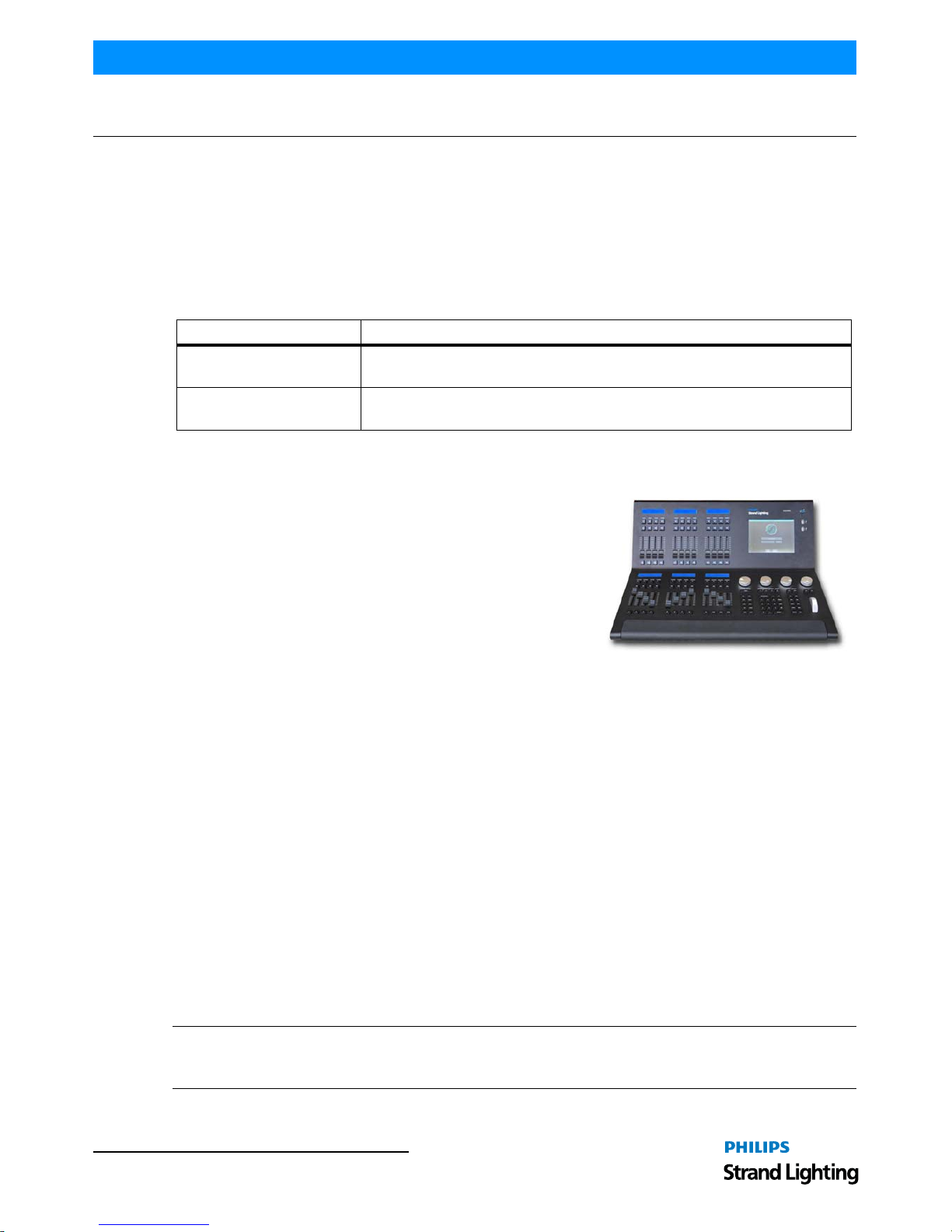
2. About the 500ML Lighting Control Console
Building on our range of lighting control consoles, the new 500ML
console from Philips Strand Lighting is designed to operate dimmers,
LED fixtures and moving lights. The 500ML console is ideal for any
event of any size – large or small.
The 8-inch TFT color touchscreen allows for fast set up. Backlit
command buttons aide in the ease of use making the 500ML console
and ideal control platform solution. If required, the unit has one
external DVI port to add a touch monitor to give even more control.
In addition, the 500ML console provides you with 24 faders. Each
may be used as a Master, Sub Master, or Playback. Equipped with
backlit Play, Pause/Reverse, and Bump buttons they allow cue stacks to be triggered as required for those busking
“moments”.
Using industry standard methods of control, the user interface is quick to understand, allowing the operation to appeal
both to the casual and professional operator alike. With a robust construction, the 500ML console provides you with
a smart way to create and play back great lighting for all your important events.
3. Included Items
Each 500ML Lighting Control Console includes the following items:
• Lighting control console
• Console dust cover
• Integrated universal voltage power supply (100 - 240VAC)
• USB key drive
•LED desk lamp
• 500ML Lighting Control C onsole QuickStart Guide (this document)
When unpacking the 500ML Lighting Control Console, be sure that you have all included items. If you are missing
any included item (as described above), please contact your Authorized Strand Lighting Dealer for assistance.
Note: Monitors, cables and other accessories are not included and are sold separately. For available accessories,
please contact you local Authorized Strand Lighting Dealer. A list of Authorized Dealers is located on the St rand
Lighting web site at www.strandlighting.com.
Style Meaning
[Button] Front panel (faceplate) hard buttons or keys. Example: Press [Button] to operate
or select.
Button LCD display menu softkeys. These are buttons that appear on the LCD display
touchscreen. Example: Press Button to operate or select.
Page 7
Control Features 5
500ML Lighting Control Console
QuickStart Guide
CONSOLE OVERVIEW
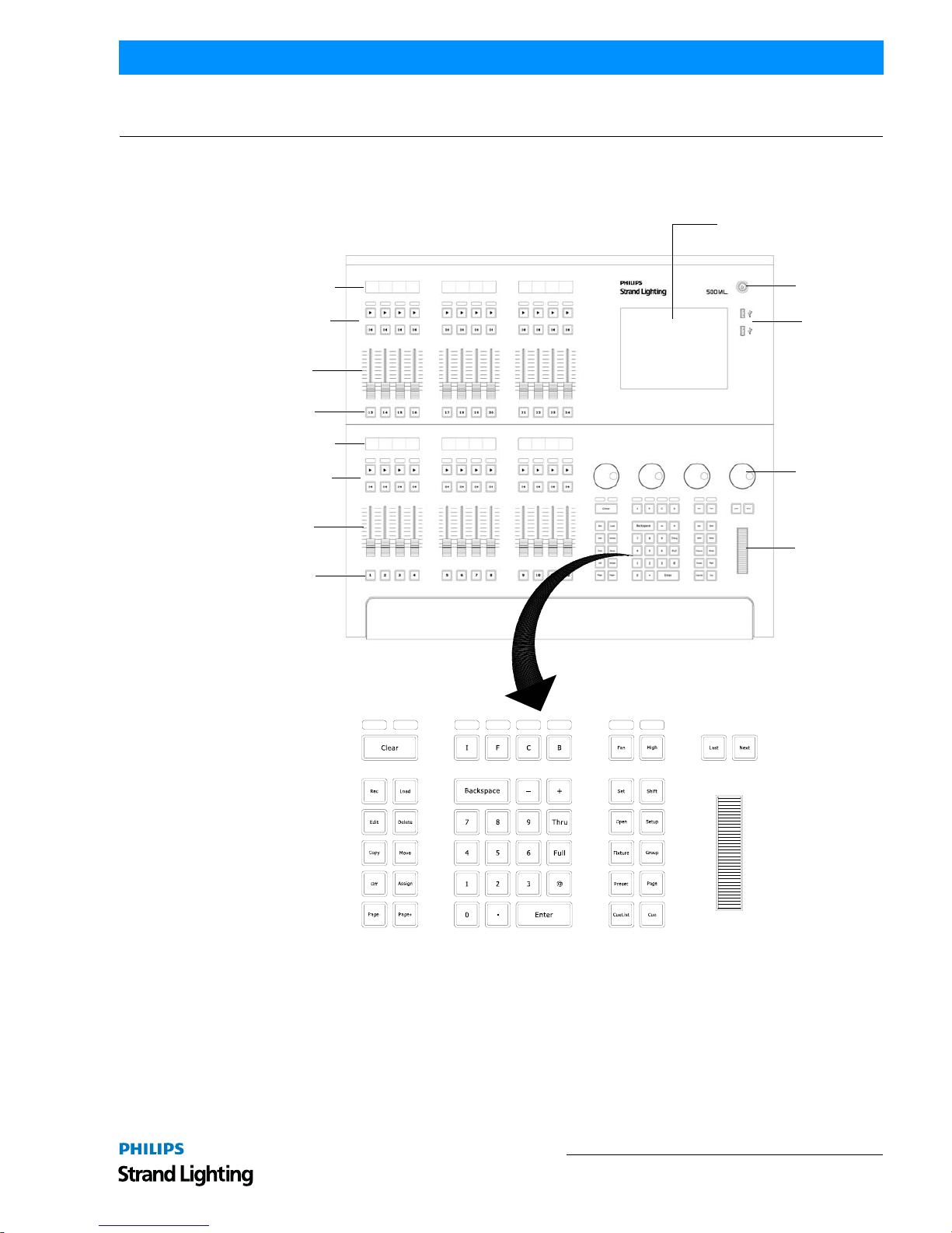
1. Control Features
Figure 1 is a quick overview of the 500ML Lighting Control Console controls.
Figure 1: 500ML Lighting Control Console Control Features
Masters (Faders)
The 500ML Lighting Control Console consists of multiple master controls, each consisting of a fader and flash, go,
pause/back buttons. Masters are grouped into blocks of four, whereas each group has a LCD screen to display the
current fader’s state.
8-Inch Color TFT Display
On / Off Button
USB 2.0 Ports
Encoders
Multifunction
Wheel
Backlit Command / Programming Keys
Bump Buttons
Faders
Fader Play / Pause /
Reverse Buttons
Status Displays
Bump Buttons
Faders
Fader Play / Pause /
Reverse Buttons
Status Displays
Page 8

QuickStart Guide 500ML Lighting Control Console
6 CONSOLE OVERVIEW
8-Inch TFT Touchscreen
The 8-inch TFT touchscreen is one of the key elements used for user interaction with the console. It provides an easyto-use and understand graphical user interface.
Command / Programming Keys
The 500ML Lighting Control Console command and programming keys correspond with the touchscreen interface.
Such keys like [Open] is used to open windows, the [Setup] button and - most important - the [Set] key, which is
used to directly alter data in many windows.
Note: Refer to "Text Conventions" on page 4 for additional information.
Example: To open up a "Fixture Pool" - window, push and hold the [Open] key and press the [Fixture] key at the
same time. Most keys that alter memories (for example. [Rec], [Edit], [Delete]) also open up a pool window if you
keep pressing the button at the same time you are striking a key like [Preset] or [Cuelist].
Encoders
The 500ML Lighting Control Console is supplied with four encoders. These encoders rotate in either direction to
quickly set desired values for different attributes during programming.
Multifunction Wheel
The console features a Multifunctional wheel which provides control of the intensity (dimming) level of the selected
fixtures and options to Scroll in Screens and can be used to increment or decrement values shown in Keypad Dialogs.
USB 2.0 Ports - Faceplate
The USB 2.0 ports on the 500ML Lighting Control Console allow users to load and save show files to a USB key
(supplied with unit). Users can also connect personal devices for charging. Additionally, the USB ports are
compatible with standard USB hubs.
Page 9
Rear Panel - External Connections 7
500ML Lighting Control Console
QuickStart Guide
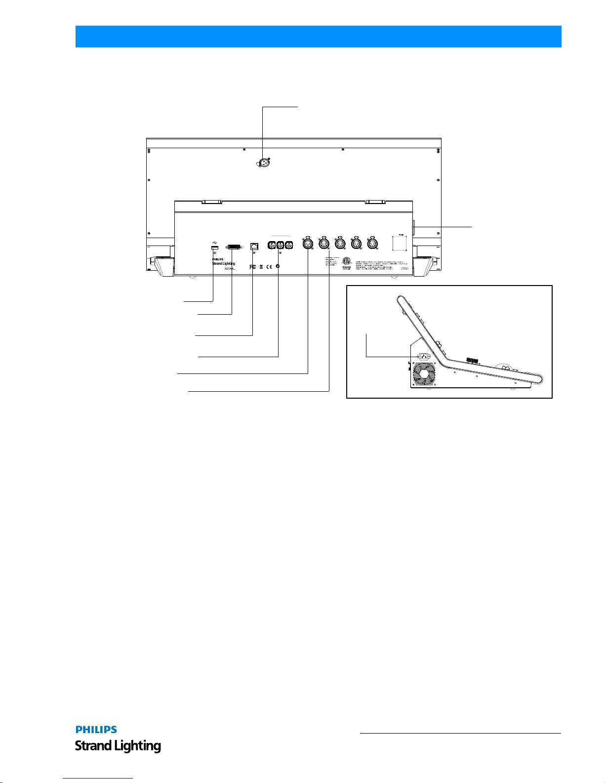
2. Rear Panel - External Connections
Figure 1 is a quick overview of the 500ML Lighting Control Console rear panel connections.
Figure 2: Rear Panel Connections
USB 2.0 Ports - Rear Panel
The USB 2.0 ports on the 500ML Lighting Control Console allow users to load and save show files to a USB key
(supplied with unit). Users can also connect personal devices for charging. Additionally, the USB ports are
compatible with standard USB hubs.
Network Port
The network port is driven by a 10/100/1000M Ethernet controller with automat ic crossover detecti on, removing the
need for cross-over cables should you wish to directly connect a Network Node to the console. The console outputs
ArtNet and Shownet.
DVI Port
The DVI Port is a DVI-D Single Link port and supports resolutions of up to 1920 x 1200; the console will
automatically detect the display resolution as well as refresh rate and will automatically enable the external screen.
DVI to HDMI adapters may be used to convert the signal to HDMI, however compatibilit y of the adapter, display,
and console should be checked prior to the show.
DeskLamp
DC 5Voperatio n
1=Shield/GN D
2=Negativ e
3=Positive
1=Ground
2=Data3=Data+
4,5=NC
1=Shield
2=Hot
3=Cold
USB
DVI
NETWORK
MIDI
IN OU T THR U
SMPTE DMX-512A
(Univers e1)
DMX-512A
(Univers e2)
DMX-512A
(Univers e3)
DMX-512A
(Univers e4)
ACPOWER
INPUT
PowerInput:100-240V~50/60Hz,0.8A Max.
PowerConsumption:80WMax.
QRCod e
500ML
This devic e complie s wit hPar t 15o fth eFC C Rules .
Operatio nis subjec t to the followin g two conditions :
1)thi sdevic e ma yno tcaus e harmfu l interference .
and 2) this devic e must accep t any interferenc e
received ,includin ginterferenc e tha tma ycaus e
undesire doperation .
Z899
For safet y instructio nan dmountin g option srefe r to user manua l
Pou rinstructio n de securit e et option s demontag eréfére rau manue l utilisateu r
Serial Number :
USB 2.0 Port
DVI Monitor Port
(monitor sold separately)
Network / ArtNET
MIDI In/Out/Thru
SMPTE In
DMX Out (x2)
Desk Lamp Connection (3-Pin XLR, 5VDC)
AC Input
AC Input (see detail)
Page 10
QuickStart Guide 500ML Lighting Control Console
8 BASICS
BASICS
1. The Fixture Library Concept
The consoles Fixture Library is divided into three parts: A System Library, a User Library and the Show Library.
Fixture Types may easily transferred between Libraries. If a fixture type is modified within the Show Library and
those changes should be available for later show files, it makes sense to transfer the fixture from the Show Library to
the User Library.
System Library
The System Library gets replaced with every Software Update. It contains around 6700 Fixtures and is maintained by
Strand Lighting. It is not editable by the user.
User Library
The User Library is fully editable by the user and is not replaced or deleted during software updates. It is stored on the
flash-disk of the console and its fixture types are available to all existing or new shows.
Show Library
The show library resides within the Showfile. Bef ore a fixture can be patched, it needs to be added to the Show
Library. The Show Library is stored within the Showfile and hence will be exported with the Showfile if a backup to
a USB Key is made. Fixtures within the Show Library are not available to other Shows. To make the Fixture T ypes in
the Show Library available to other shows, they need to be transferred to the User Library first.
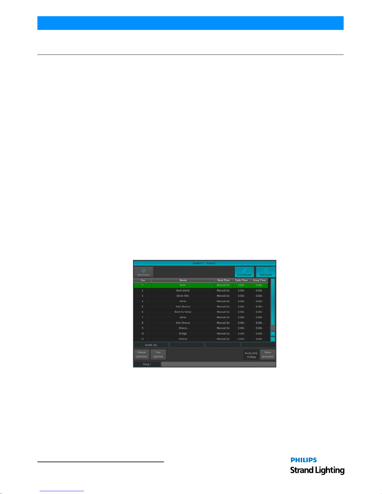
2. Screens
The console shows context sensitive screens for each step of the show creation. This way it only shows functionality
you need for a specific task. As an example, the "Cuelist View" Window (Figure 3) will only show information that is
necessary to understand and read your cuelist, whereas the "Programmer Window" (Figure 4 on page 9) will only
show information needed for value entry.
Figure 3: Cuelist View
Page 11
Screens 9
500ML Lighting Control Console
QuickStart Guide
Figure 4: Programmer Window
Opening Screens and Dialogs
The 500ML console provides easy and logical ways to open the context sensitive screens. As an example, pressing
[SETUP] will show the Setup Screen, which is used for general configuration of the console, such as adding Fixtures
to the Show or setting the IP Address of the Network Interface.
All of the Pool Windows containing Fixtures, Groups, Presets or Cuelists as well as the Fader Page Directory may be
opened by issuing a long press on the [Open] key, followed by the key of the Pool Window you would like to open:
• [OPEN] + [FIXTURE] will open the Fixture Pool Window
• [OPEN] + [GROUP] will open the Gro up Pool Window
• [OPEN] + [PRESET] will open the All Preset Pool Window
• [OPEN] + [I] will open the All Preset Pool Window
• [OPEN] + [F] will open the "Intensity" Preset Pool Window
• [OPEN] + [C] will open the Color Preset Pool Window
• [OPEN] + [B] will open the Beam Preset Pool Window
• [OPEN] + [CUELIST] will open the Cuelist Pool Window
• [OPEN] + [PAGE] will open the Fader Page Directory Window
Pressing the [OPEN] key provides you with the Open Toolbar, which may also used to open the different Pool
Windows. Additionally the Open Too lbar may be used to open the Output Window, indi cating the currently output
values.
Figure 5: Open Toolbar
In addition to that, the Command keys found on the Keypad like [RECORD], [LOAD], [EDIT], [DELETE], [COPY],
[MOVE], [OFF] and [ASSIGN] will, in a similar fashion to the [OPEN] button open up Pool Windows as well if they
are pressed while striking any of the Object keys, whilst keeping the initial comm and in the command line. This is
very useful to quickly navigate around the console during programming. As an example: Holding [RECORD] while
pressing the [GROUP] button opens up the Group Pool and keeps the Record Keyword in the command line,
allowing to directly record the Group.
Command Line Syntax
In general the Command Line Syntax needs to be entered in "Action - Source - Target" form. When no Action is
specified, the source Item will be selected. See Table 1, “Command Line Syntax,” on page 10 for more information.
Page 12
QuickStart Guide 500ML Lighting Control Console
10 BASICS
Table 1: Command Line Syntax
Commands interacting with a visual object (such as a Pool Item or a Faders Pause/Back Button) will be executed
automatically once they are syntactically correct. However, commands that do not interact with visual elements need
to be executed by pressing the [ENTER] key.
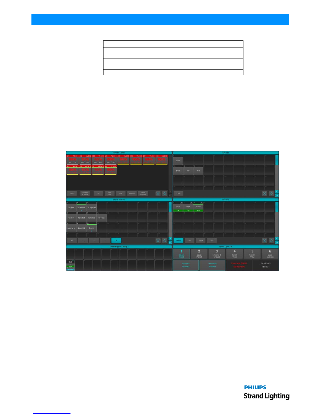
External Monitor
If an external monitor (sold separately) is connected, the monitor provides enhanced overview over your show file. It
consists of 6 different views that show Fixture, Group, Preset and Cuelist Pools, as well as fader labels. Pool Items
may either be selected or deselected by using a standard USB Mouse or a touchscreen. Fader labels also provide you
with a quick overview of assigned Masters. Additionally, the current date and time and incoming Timecode is shown
and the Timecode input may be enabled or disabled.
Figure 6: External Monitor Screen
Action Source Target
[RECORD] [PRESET] [5]
[PRESET] [5]
[COPY] [PRESET] [5] [PRESET] [8]
[MOVE] [PRESET] [5] [PRESET] [8]
[ASSIGN] [CUELIST] [2] [GO] or [PAUSE / BACK]
Page 13
To Begin Using the Console 11
500ML Lighting Control Console
QuickStart Guide
OPERATION
1. To Begin Using the Console
Unpack Console and Accessories
Before you can use the console, unpack it and its accessories from the shipping carton. For a complete list of included
items, refer to "Included Items" on page 4.
Connect Console to Any Accessories and Power
Note: Before connecting any accessories to the 500ML Lighting Control Console, the console must be located on a
sturdy and flat surface in a dry, dust free environment.
Connect all optional accessories such as USB keyboard, mouse, touchscreen, etc. to the console.
Connect DMX cables to the console’s DMX output ports.
If you are using ArtNet for data output, also connect the network cable to the consoles network port.
Use the supplied AC power cable to connect the console to a grounded, AC power source. The console operates on an
AC voltage of 100 to 240VAC.
Refer to Figure 2 on page 7 for console connections.
Boot the Console
After making all the necessary connections to the DMX control and/or ArtNET networks, external peripherals, etc.
the console is ready for use.
• To begin using the console, press the power button on the right hand side next to the touchscreen (refer to Figure 1
on page 5).
• The console will now start to boot. Additionally, the boot menu offers some test and maintenance utilities. The
500ML Lighting Control Console will perform a system check during boot up. Once the system is ready to use, the
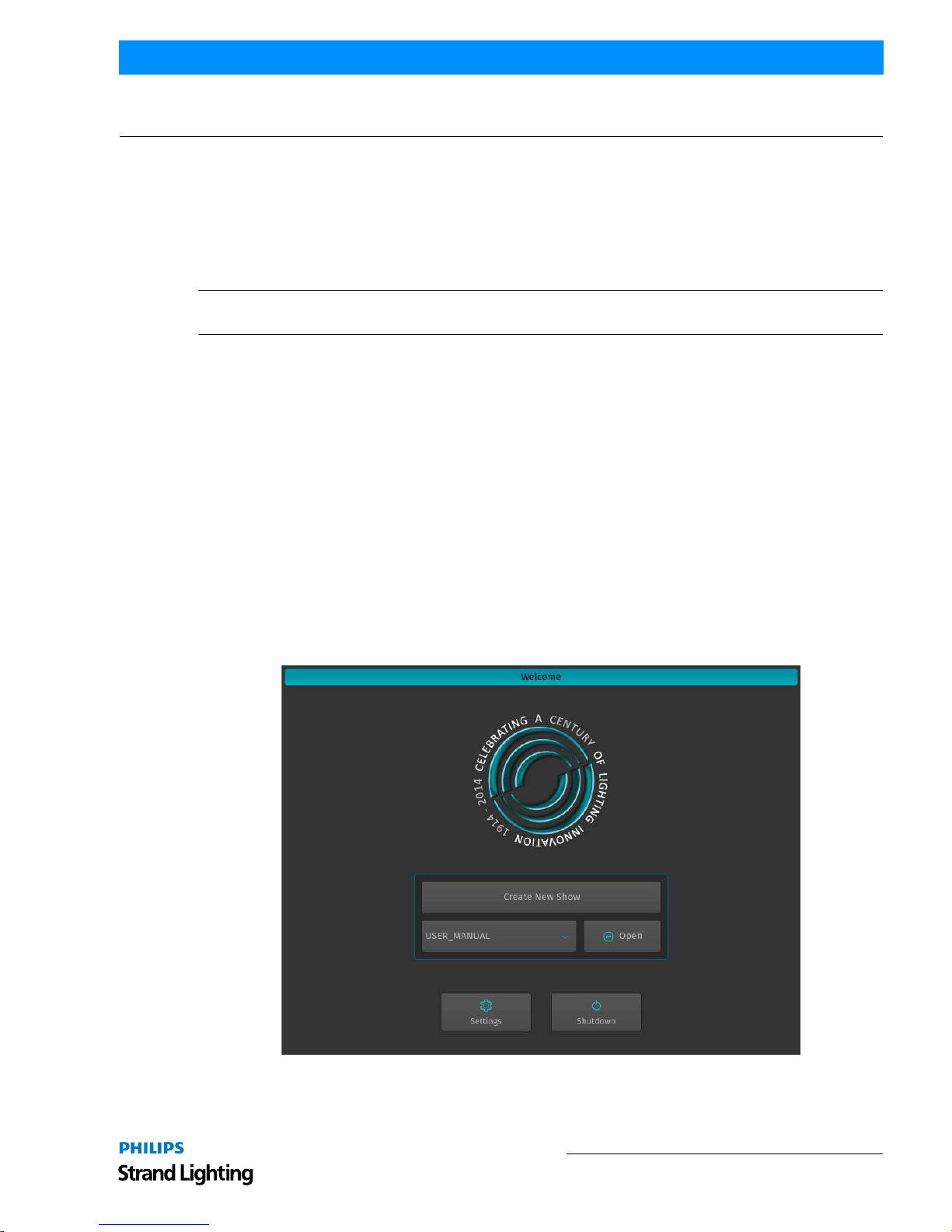
Welcome screen will appear (Figure 7).
Figure 7: Welcome Screen
Once the Welcome Screen appears, you may either start creating a new show file or load an existing one.
Page 14
QuickStart Guide 500ML Lighting Control Console
12 OPERATION
2. Working with Shows
Show files contain all of your show related settings like fixture schedule and patching, input settings, groups, presets,
cues, master assignments, etc. Multiple shows may reside on the console and the amount of shows is only limited by
hard disk memory. However it is advised to regularly backup old shows to a USB key and delete them off the
consoles memory.
3. To Create or Load a Show
When the Welcome screen appears, you are given two options:
• Create a New Show or,
• Load an Existing Sh ow (via a saved showfile*)
Note: *Showfiles contain all of your show related settings like fixture schedule and patching, input settings, groups,
presets, cues, master assignments, etc.
Creating a New Show
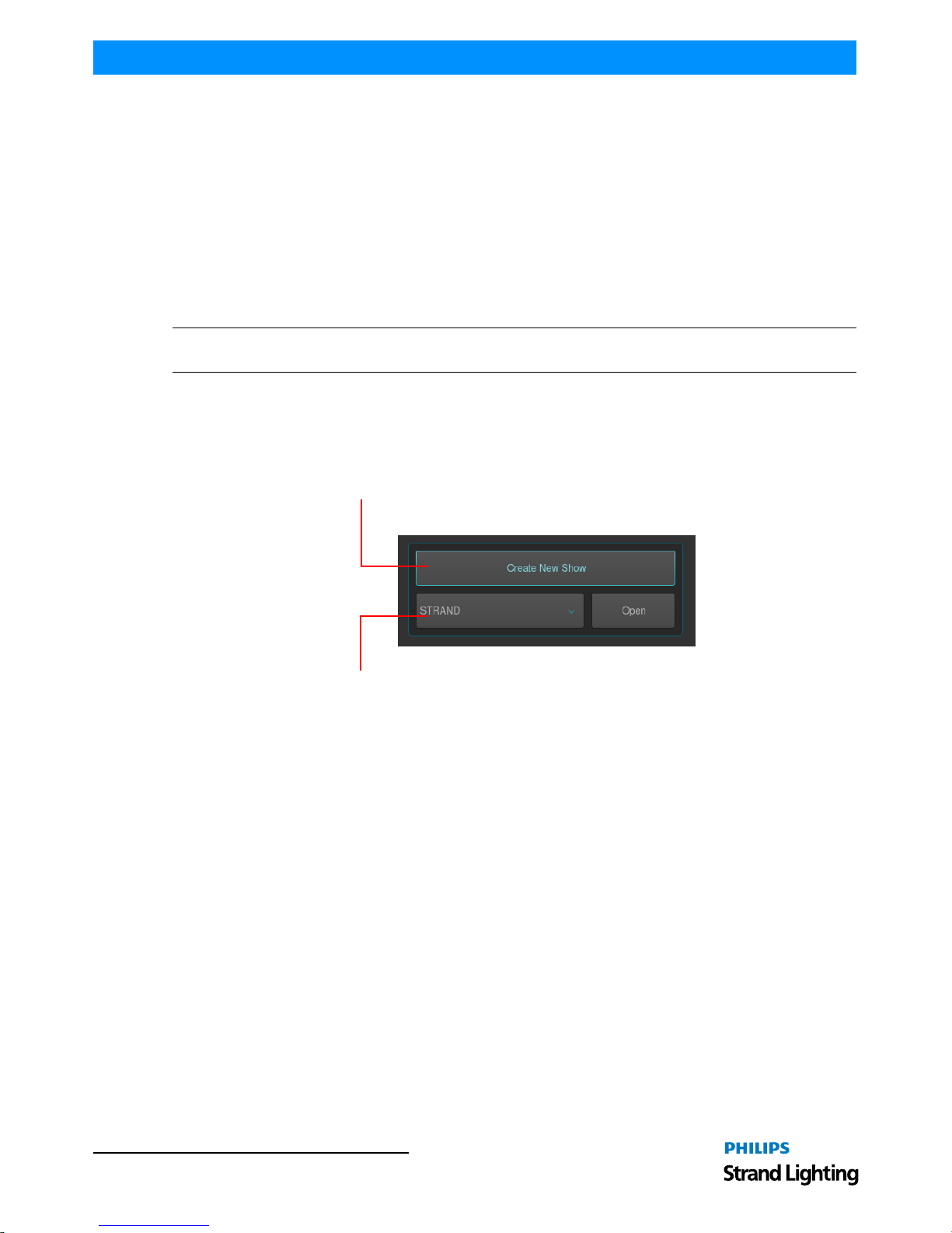
On the console’s 8-inch TFT touchscreen display, hit the Create New Show button on the Welcome Screen (refer
to Figure 8).
Figure 8: Create New Show Option
This will open up a virtual keyboard on the console screen, as illustrated in Figure 9 o n page 13, to enter the name of
the show to be created.
You may also enter values by using an external USB keyboard (by others, sold separately) anytim e the keyboard
dialog is shown. As soon as you hit the Enter button a show file with a name given is created.
Press to create a new show
Dropdown menu to load an existing show
Page 15

To Create or Load a Show 13
500ML Lighting Control Console
QuickStart Guide
Figure 9: Touchscreen Keyboard & Showfile Name Field
Loading an Existing Show
To be able to open a show, you first need to close any open shows. Do this by pressing [SETUP] and hitting the Close
Show button on the Setup Toolbar. As soon as all shows are closed, the console will return to the Welcome Screen as
shown in Figure 8 on page 12.
After selecting the show file name from the drop down menu (refer to Figure 8 on page 12) a, hit the Open button
the console’s 8-inch TFT touchscreen display.
Note: Shows stored on a USB Key need to be imported into the console memory before they can be opened.
Importing Shows from a USB Key
From the W elcome Screen hit the Settings button as shown in Figure 7 on page 11. Or, you can open the Setup Dialog
by selecting the [SETUP] key on the front panel instead.
Once the Setup Menu is shown, switch to the USB tab and hit the Show Import button as illustrated in Figure 10.
Figure 10: Setup Menu - USB Tab - Show Import
Showfile Name Field
Page 16
QuickStart Guide 500ML Lighting Control Console
14 OPERATION
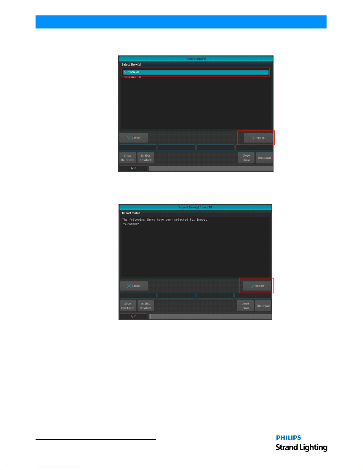
A list of shows will appear. Select the show or shows you would like to import and hit the Import button on the
touchscreen display.
Figure 11: Select Show to Import
A confirmation screen will appear with a brief summary of the show or shows to be imp orted as displayed i n Figure
12. Click on Import button to start the process of loading the show(s).
Figure 12: Import Show(s) from USB - Import Status of Selected Shows
Page 17
To Create or Load a Show 15
500ML Lighting Control Console
QuickStart Guide
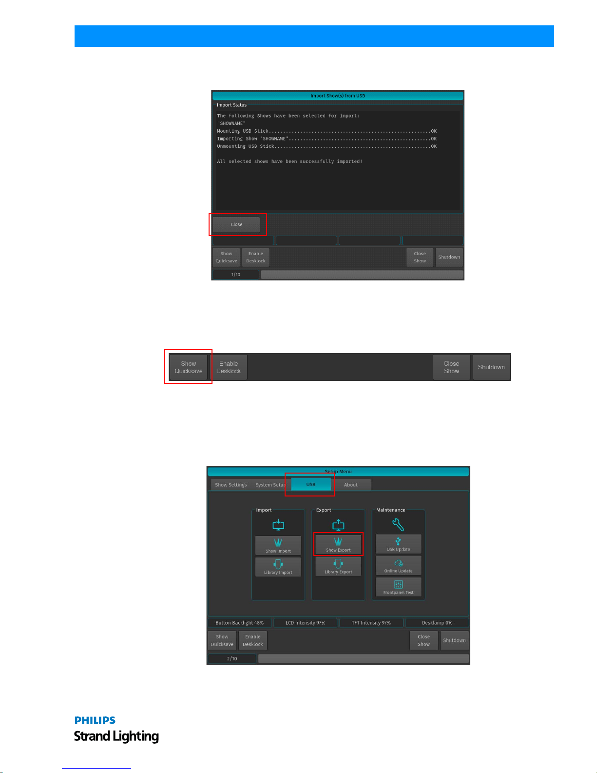
After the loading process begins, the Import Status box will now display the import process. After the process
finished, click on the Close button.
Figure 13: Import Show(s) from USB - Import Status of Selected Shows - Completed
Saving Show Files
We recommend to save your show frequently to insure information is not lost in case of a power loss, interruption,
etc. You may do this by pressing [SETUP] and hitting th e Show Quicksave button on the Setup Too lbar.
Figure 14: Setup Toolbar - Show Quicksave
Exporting a Show to USB Key
At the Welcome Screen, hit the Settings button. Should you already be running a show, open the Setup Dialog by
pressing the [SETUP] key on the front panel instead.
Once the Setup Menu is shown, switch to the USB tab and hit the Export Show button as illustrated in Figure 15.
Figure 15: Setup Menu - USB Tab - Show Export
Page 18

QuickStart Guide 500ML Lighting Control Console
16 OPERATION
The next screen will display a list of shows in the console’s memory. Select the show or shows you would like to
export (copy) to the USB key. Then, hit the Export button on the touchscreen display to export them to the USB key.
Figure 16: Select Show(s) to Export Screen - Exporting Shows to USB Key
A confirmation screen will appear confirming your selection(s) to be exported as shown in Figure 17. Click the
Export button to export the show(s) to the USB Key. The Export Status field will now display the export process.
Figure 17: Export Show(s) to USB Screen - Confirmation Scr een
Page 19

To Create or Load a Show 17
500ML Lighting Control Console
QuickStart Guide
When the process finished successfully, click on the Close button as indicated in Figure 18.
Figure 18: Export Show(s) to USB Screen - Export Completed
Closing a Show
To load a show (as described in "Loading an Existing Show" on page 13), you must close any open shows. Do this by
pressing [SETUP] and then pressing the Close Show button on the Setup Toolbar (Figure 19).
Figure 19: Setup Toolbar - Closing a Show
Note: If there are no shows loaded, the 500ML Lighting Control Console will not output DMX.
Page 20

QuickStart Guide 500ML Lighting Control Console
18 Programming
PROGRAMMING
1. Fixture Setup
Adding Fixtures to a Show
In order to add and patch fixtures, please press the [Setup] key on the consoles front panel. A menu will appear on the
touchscreen display, presenting you several options. Choose Add Fixtures in the Setup Menu screen (Figure 20).
Figure 20: Setup Menu
The Select Fixture from Show Library screen (Figure 21) will appear allowing you to pick t he fixture type from the
show library.
• If the show library does not yet contain the fixture of the choice, click on Add Library to add fixtures from the System or User Library to the Show.
• If the list already contains the desired fixture type, select it and click on Next, which will skip the nex t two steps.
Figure 21: Select Fixture from Show Library Screen
Page 21

Fixture Setup 19
500ML Lighting Control Console
QuickStart Guide
A library selection screen will appear (Figure 22) allowing you to select where to select and import fixtures.
• If you would like to add a predefined Fix ture Type, select on Factory Library.
• If you would like to add a User created or User modified fixture, select User Library. Click on Next when done.
Figure 22: Select Library Screen - Library Choices to Add Fixtures
After clicking Next for the Factory Library selection, a fixture selection screen as shown in FIG will appear allowing
you to select a predefined fixture.
• You may search for fixtures using the search field shown in the top part of the screen. In order to complete the
examples shown in this guide, search for "vari 3000" and select the Philips V ari-Lite VL3000 Spot from the list. To
clear your search, click the Reset Filter button. After selection, click on the Next button.
• Alternatively, you may select the fixture by using the Manufacturer, Type and Mode fields.
Figure 23: Select Library - Fixture Search and Selection Screen
After selecting a fixture for your show, a new screen (Figure 24 on page 20) will appear confirming your fixture
selection. In this screen, you will be required to enter the following information:
• Fixture Count - The number of this type of fixture being added to the show.
Search Field
Page 22

QuickStart Guide 500ML Lighting Control Console
20 Programming
• Set User Numbers - Starting DMX Address for the fixtures.
• Default Fixture Settings - You can select Invert Pan, Invert Tilt or React to Master (react to Grandmaster).
In this example 12 fixtures will be added, with User Number starting at 501. After setting these parameters, click
Next.
Figure 24: Enter Fixture Count Screen
Patching Fixtures
As shown in Figure 25, this window is used to patch (assign) fixtures to the DMX Universes. There are three different
patch options available to choose from:
• No Patch - The fixtures will be added but not patched.
• Manual Patch - The fixtures will be added and patched to the address and universe user specified
• Auto Patch - The fixtures will be patched at the next free address of the selected universe automatically.
For this exercise, choose "Manual Patch", select Universe 1 and set the start address to 1 and click on Finish.
Figure 25: Patch new Fixtures Screen
Fixture Selected
Number of Fixtures Being Added
Fixture Starting
Address
Fixture Settings
Selection
Starting DMX Address Field
Page 23

Working with Fixtures 21
500ML Lighting Control Console
QuickStart Guide
2. Working with Fixtures
Selecting Fixtures
Before you can start altering any values or programming, you need to select the fixtures you would like to work with.
There are four different ways to select your fixtures.
Selection Order
The order in which you select fixtures determines how sub-selection and fanning are applied to th em. For example,
applying a fanned value or an odd sub-selection to them af ter selecting fixtures 501 thru 505 will appear different
than if you selected fixtures 501 + 503 + 502 + 505 + 504.
The selection order matters during programming and is recorded as part of groups, bu t is not recorded in presets or
cues.
Note: Because the 500ML console records the selection order as part of groups, you can select the group and use the
Next and Back keys to sub-select each fixture in a particular order. By controlling the selection order when you
record the group, you can work through a series of fixtures in the order they are physically positioned in the rig,
instead of in numerical order. If used in a controlled manner, this can be a very powerful way to generate very nice
effects as well.
Selecting Fixtures Using Keypad / Command Line
Figure 26: 500ML Console - Command / Programming Keys
To select fixtures using the command/programming keys, simply do so by typing their user numbers as assigned in
"Adding Fixtures to a Show" on page 18. You may use the [THRU], [+] and [-] keys to further extend your selection
to include some or all fixtures.
Figure 27: Command Line Interface - Fixture Selection
Fixture selection examples:
• [501] [THRU] [ENTER] will select all fixtures following fixture 501 until a different fixture type starts, or a gap in
the numbering scheme is detected.
• [501] [+] [502] [ENTER] will select fixtures 501 and 502.
• [501] [THRU] [510] [ENTER] will select all fixtures from fixture 501 to 510.
• [501] [THRU] [510] [-] [503] [ENTER] will select all fixtures from fixture 501 to 510 except 503.
Note: You do not need to press the [Fixture] key prior to the fixture numbers, as the console assumes you will select
a fixture when entering numbers. To deselect all fixtures, just type [0] [ENTER] on the keypad.
Page 24

QuickStart Guide 500ML Lighting Control Console
22 Programming
The keypad does also have special functions for extended fixture sub-selection which can be applied on your current
selection. Refer to "Fixture Sub-Selection" for more information.
Selecting / Deselecting Fixtures Using Fixture Pool Window
Press and hold the [OPEN] key and press the [FIXTURE] button. The Fixture Pool window will open up (Figure 28).
You may now select or deselect fixtures by sim ply clicking on them.
Figure 28: Fixture Pool Window
Selecting Fixtures Using a Previously Recorded Group
Press and hold the [OPEN] key and press the [GROUP] button. The Group Pool window will open up. In this
window, you can select and deselect fixture groups by clicking on them. You may also select a Group from within the
Group Pool shown on the external monitor.
You can also select a Group using the Command Line Interface: [GROUP] [1] [ENTER].
Note: "Working with Groups" on page 24 for more information about working with Group Pools.
Fixture Sub-Selection
Fixture Sub-Selection provides additional fixture selection features based on your current fixture selection set. This
means that all sub-selection functions are applied to your current fixture selection. If you do not have fixtures
selected, the Fixture Sub-Selection will be applied to all fixtures instead. If you select any of the sub-selection
functions, the console will remember the full selection th at you made using the keypad and apply all functions to
Fixture Sub-Selection memory.
Most sub-selection functions are easily accessed by using the Selection Toolbar (Figure 29). To open the Selection
Toolbar, click on the first button that reads Fixture Select ion from within the Main Toolbar. Clicking on Close will
close the Selection Toolbar. However, some sub selection functions are accessed directly by hard keys on the console
or the keypad.
Figure 29: Main Toolbar to Selection Toolbar
Main Toolbar
Selection Toolbar
Page 25

Working with Fixtures 23
500ML Lighting Control Console
QuickStart Guide
Selecting Fixture X out of Y
The console offers a built in modulo sub-selection function that allows the selection of every Xth fixture out of Y.
The syntax is uses [.] [.] for the "out of" portion of the command.
In the following example, we are going to select every first fixture out of every three fixtures:
1) To select fixtures 501 to 512:
2) Type [1][.] [.] [3] [ENTER] on the keypad.
3) To select every second fixture out of three, type [2][.] [.] [3] [ENTER]
4) To select every third fixture out of three, type [3][.] [.] [3] [ENTER]
Please note you may also combine the modulo function with more advanced functions:
1) Select fixtures 501 to 512
2) Type [1] [+] [2] [.] [.] [3] [ENTER] on the keypad translates into "Select each first and second fixture out of
three".
Or:
1) Select fixtures 501 to 512
2) Typing [1] [THRU] [3] [+] [5] [.] [.] [5] [ENTER] on the keypad translates into "Select each first through
third and fifth fixture out of five fixtures".
Assigning Names to Fixtures
You may decide be tween different ways should you wish to rename your fixtures to make them more identifiable
within the Fixture Pool, programmer and fixture configuration dialogs:
• Simultaneously press the [FIXTURE] and [ASSIGN] keys. The Fixture Pool win dow will open.
• The command line wil l still read Assign.
• Press the [ASSIGN] key again. The command line will read Name.
• Select the fixture you wish to rename from within the Fixture Pool Window (see "Selecting / Deselecting Fixtures
Using Fixture Pool Window" on page 22).
• Enter Fixture Name window with keyboard will appear as shown in Figure 30.
Figure 30: Entering / Changing a Fixture Name
Fixture Name Field
Page 26

QuickStart Guide 500ML Lighting Control Console
24 Programming
3. Working with Groups
About Groups
Groups are meant as a programming aid and are a quick way to access specific groups of fixtures. As opposed to the
theatrical term "Group" they do not store any values. They only store information about fixture selection and
selection order.
Creating a Group
To record your first group, start out by selecting fixtures 501 through 512 by using the Keypad (refer to ""Selecting
Fixtures" on page 21 for more information).
Once fixtures are selected to be a Group, press and hold the [REC] button and then press the [GROUP] button. The
Groups pool window (Figure 31) will appear. Select any empty slot (an empty box with a number in the corner) to
store a new Fixture Group.
Note: You may also hit the [REC] key only, and select an empty Group Item in the External Monitors Group Pool
Window.
Figure 31: Groups (Pool) Window
Note: You may label any item by pressing [ASSIGN] keypad button twice. The command line will read "Label".
Now select the Item you would like to label and type in the name.
Updating Groups
To update a group, you must first select the fixtures you would like to remove or add to a group. See "Selecting
Fixtures" on page 21 for more information.
Press and hold the [REC] key and then press the [GROUP] button. The Groups pool window (Figure 31) will appear.
Select the Group you would like to update.
Page 27

Working with Values 25
500ML Lighting Control Console
QuickStart Guide
If you did not select an option from the Record Toolbar, a dialog window will open (Figure 32) asking you what you
wish to do. Select the desired action by click the appropriate button on the screen.
Figure 32: Merge or Replace Group Inquiry Window
Selecting and Deselecting Groups
Press and hold the [OPEN] key and then press the [GROUP] button. The Groups pool window (Figure 31 on page 24)
will open. You can select an d deselect fixture groups by clicking on them. You may also select a Group on the
external monitor (if connected). To learn how to create a Fixture Group, see "Creating a Group" on page 24.
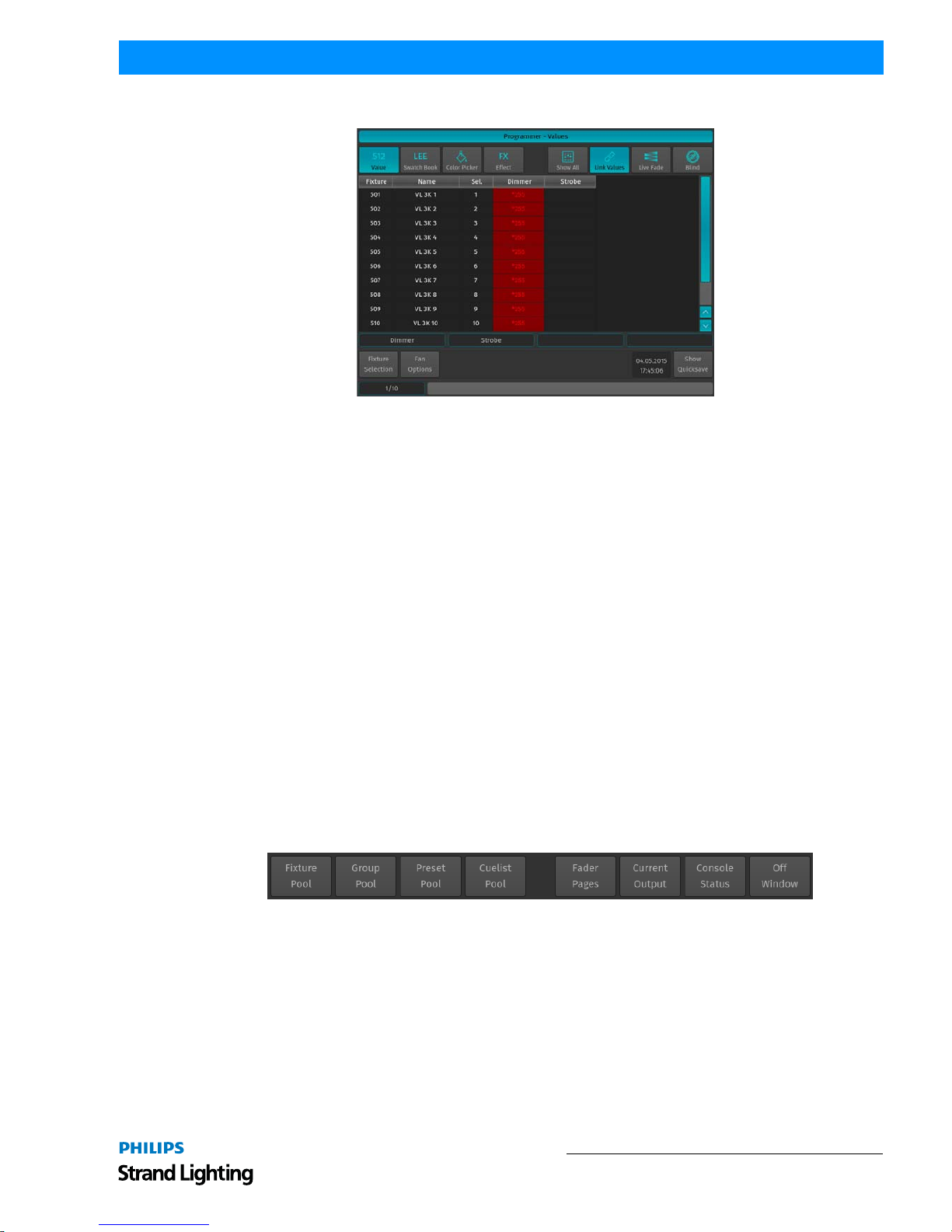
4. Working with Values
The console follows the popular "Programmer" concept. This section will explain the concept in detail.
Figure 33: Programmer - Values Screen
What is the Programmer?
The "Programmer" is the place where all of the programming happens. As soon as you modify a fixture’s attribute
values by using any of the input methods for values, it will be displayed in the programmer.
The programmer always takes precedence over cuelists, this way you can, at any point in a show, modify the look on
stage. For a more in-depth look on how priorities are managed in the console, have a look at "Error! Reference source
not found.".
Page 28

QuickStart Guide 500ML Lighting Control Console
26 Programming
Fixture Attribute Values
Without Values
Figure 34 shows how the programmer appears when fixtures are selected without values assigned in the programmer.
They are still outputting values set by cuelists or their default values set in the library.
Figure 34: Programmer Without Values
With Values
Figure 34 illustrates how the programmer appears when fixtures are selected with values assigned in the programmer.
The programmer takes precedence over cuelist output for the attributes with values in the programmer. However,
these values would not be recorded.
Figure 35: Programmer With Values
Modified (Touched) Values
Figure 34 shows how the programmer appears when attribute values are modified (touched) in the programmer. The
programmer takes precedence over cuelist output for all attributes with values in the programmer. As soon as values
are "touched" (indicated by red background color of the corresponding cell) they can be recorded.
Figure 36: Programmer with Modified (Touched) Values
Emptying the Programmers "Content"
In order for all playbacks to re-gain control over the fixture attributes contained in the programmer, the programmer
needs to be cleared out. This happens in three steps with each press of the [CLEAR] key.
The first press of the [CLEAR] key will un-touch all values, however they are still in t he programmer overrid ing the
playback. The second press of the [CLEAR] button will remove all values from the programmer and playback values
will be output again. The third and last press will unselect all fixtures that were selected.
Note: In case you accidentally cleared your programmer content, press [SHIFT] and [CLEAR] simultaneously to
revert to the previous values.
Page 29

Working with Values 27
500ML Lighting Control Console
QuickStart Guide
The LEDs above the [CLEAR] and the [I], [F], [C] and [B] buttons indicate the current state of the values:
Figure 37: Clear and IFCB Buttons
Assigning Values to Fixture Attributes
500ML Lighting Control Console segregates common fixture parameters into four groups:
• [I] - Intensity Paramet e r (Di mmer, strobe, duration, etc.)
• [F] - Focus Parameters (Pan / Tilt position)
• [C] - Color Paramet ers
• [B] - Beam Parameters (Gobos, Zoom, Focus, etc)
Note: Remember, the programmer takes precedence over the underlying playback. Press the [CLEAR] key three
times to empty the programmer contents.
Altering Intensity (Dimmer Values) Using Multifunction Wheel
The Multifunction (dimmer) wheel on the right hand side of the console faceplate (as indicated in Figure 1 on page 5)
can be used to increment up or decrement down the dimmer values of the selected fixtures.
Altering Intensity (Dimmer Values) Using Keypad
Numerical dimmer values (levels) may be applied directly to selected fixtures using the command line interface by
typing [@] followed by either [FULL] or the intensity value (in percent) followed the [ENTER] key.
Keypad Syntax
Table 2: Keypad Value Syntax Entry
Keypad Entry Meaning
[@] [FULL] Will set the selected fixtures to 100%
[@] [@] Will set the selected fixtures to 100%
[@] [.] [VALUE] Will set the selected fixtures Intensity DMX Value to [VALUE]
[VALUE A] [THRU] [VALUE B]
Will fan the Intensity for selected fixtures from [VALUE A] to [VALUE B]
For Example: [0] [THRU] [100] with 3 selected fixtures will set fixture 1 to 0%, fixture 2 to 50%
and fixture 3 to 100%.
[VALUE A] [THRU] [THRU] [VALUE B]
Will fan the Intensity for selected fixtures from [VALUE A] to [VALUE B] and back to [VALUE A].
For Example: [0] [THRU] [THRU] [100] with 5 selected fixtures will set fixture 1 and 5 to 0%,
fixture 2 and 4 to 50% and fixture 3 to 100%.
LED Color State
Green Fixtures are selected (Only applies to [CLEAR] key)
Yellow There are values in the programmer and the corresponding attribute group
Red
There are modified (touched) values in the programmer and the
corresponding attribute group that may be recorded
Page 30

QuickStart Guide 500ML Lighting Control Console
28 Programming
Altering Parameters Using Encoders
To change fixture parameters, select either a fixture or group of fixtures (see "Selecting Fixtures" on page 21). Select
the parameter group of the parameter to be changed - [I], [F], [C], or [B]. Repeatedly press the [I], [F], [C], or [B]
button until the toolbar indicates the desired parameters. Alternatively, just click on one of the buttons shown in the
toolbar. Using encoders (as indicated in Figure 1 on page 5), change the parameters as desired. Make sure the
Programmer Window is set to Value mode as shown in Figure 38.
Figure 38: Programmer - Values Window
Example:
• To change the pan and tilt parameters for Fixture Group 1, select Fixture Group 1.
• Press the [F] (focus parameter) key. The Programmer window will appear and the encoder labels will now read the
selected features of pan and tilt.
• To cycle through the available feature groups (i.e., from Position to Pan/Tilt speed), simply press the feature button
again or press the appropriate button on the IFCB Toolbar.
Note: To quickly toggle through values in 25% steps, just press on the Encoder knob, or touch the Encoder label on
the screen. To alter the attribute values in a finer manner, hold the [SHIFT] key pressed while turning the Encoders.
Page 31

Working with Values 29
500ML Lighting Control Console
QuickStart Guide
Altering Color Values Using Swatch Book
Another option to set colors is via the internal color swatch book. To open up the Swatch Book, press the Swatch
Book button found in the programmer window. Remember, to open the programmer just press either of the Attribute
Keys [I], [F], [C] or [B]. Once the Swatch book window (Figure 39) opens, simply select the color you desire.
Figure 39: Programmer - Swatch Book
Filter Gels by Manufacturer
Within the Programmer - Swatch Book window, use the filter drop down menu to display filter gels by manufacturer.
Figure 40: Swatch Book - Filters by Manufacturers Drop Down Menu
Filter Gels by Search Function
Another option to look for colors is the integrated text search field. Just type what you are searching for into the
search field. If you do not have a USB Keyboard attached, click on the keyboard butt on to open up the on-screen
keyboard.
Figure 41: Swatch Book - Filters by Search Function
Note: You can combine full text searches with the manufacturer drop dow n menu. For example, entering "Amber"
into the search field and setting the manufacturer filter to LEE will only show amber gels (with amber in their
description) manufactured by LEE.
Page 32

QuickStart Guide 500ML Lighting Control Console
30 Programming
Altering Color Values Using Color Picker
To open up the color picker , press the Color Picker button found in the programmer window as indicated in Figure 42.
The center triangle sets the Saturation and brightness, whereas the outer circle sets the colors Hue. As opposed to
other consoles, the 500ML does not store HSB color information in Cues, hence cues will cross fade in RGB or CMY
color space.
Figure 42: Programmer - Color Picker
Fanning (Spreading) Values Across Fixtures
Fanning is a very useful function used to spread values across a range of fixtures. A quick way to
fan intensity values is described in "Altering Intensity (Dimmer Values) Using Keypad" on page
27. The fanning engine of the 500ML console does not stop there.
Fanning of values may be applied to any fixture attribute, and to effect offsets, size, speed, and
duty cycle. The default Fan Settings should have most situations covered, but they may be
changed using the Fan Options toolbar.
To activate fanning of attributes, press the [FAN] key on the consoles faceplate. The LED above
the [FAN] button will light up to indicate the fan functions status. The fan function will remain
active until you press the button again. However, if you keep holding the [FAN] button for a longer amount of time,
the Fan Function will only be turned on while maintaining a button press.
Bear in mind that the fixture selection order is important when fanning. For more information please see "Selection
Order".
Note: Take care when choosing the initial base value for the fan, as the attribute values can neither go below 0%, nor
higher than 100%. Make sure there is enough of the value range left for the value to fan.
5. Presets
Working with Presets
Presets aid to simplify the programming process by allowing user-defined 'elements' to be created and then used as a
toolkit to build your cues. Once you created a Preset, such as a couple of moving lights pointing at a particular
position on stage, you may recall those settings at any point, and record them into cues.
The biggest advantage of using Presets is that they are only stored into cues as a reference, rather than the parameter
values that the Preset contains. If you later decide to change the Preset, all cues that have b een recorded using this
Preset are also changed. This is especially useful if, in example, the position of a set-piece on stage is moved , and
moving lights have been programmed to light it. The preset can be updated once to accommodate the change, rather
than reprogramming the change in every cue lighting the set-piece.
Page 33

Presets 31
500ML Lighting Control Console
QuickStart Guide
This is a very powerful feature that allows you to make global changes to the show very simply and qui ckly, rather
than having to re-program every cue individually.
Presets allow intensity, focus (position attributes), color, and beam parameters to be recorded to be easily accessible
during programming and live operation.
• Presets are stored in Preset pools, which are divided into Sub Pools: All , In tensit y, Focus, Color & Beam.
• Each Pool type will filter attributes stored into the presets by its equivalent type.
• An All Preset Pool will store all attributes, whereas a Color Preset Pool will only store color attributes.
Presets are only applicable to fixtures that had values set while storing the preset, but may be recalled by some of the
fixtures only.
For example, you have recorded a pr eset containing only Pan and T ilt for Fixtur es 501 thr ough 510. This pr eset is not
applicable to Fixtures 511 and 512. However this preset may also be recalled by fixture 501 and 504 only.
For more information on recalling presets, please see section "Recalling a Preset as a Reference" on page 32.
If you wish to use a Preset as a programming tool, where later changes to the Preset will not cause cues to be updated,
please read section "Recalling a Preset as a Hard Value" on page 32.
Storing a Preset
Once you created a look you would like to store as a preset, press and hold the [R EC] key and simultaneously press
the [PRESET] key. The Preset Pool (Figure 43) window will open. Select the Preset Pool type using the Preset Pools
toolbar and select any empty pool item to store the preset - i.e., Preset 1.
You may select different record options from the Record toolbar after pressing the [REC] button.
Figure 43: Preset Pool Window - All Presets
Note: Y ou may label any item by pressing [ASSIGN] button twice. The command line will read "Label". Now select
the Item you would like to label and type in the name.
Updating Preset Contents
Sometimes it is necessary to update the contents of a Preset.
Touch the attributes you would like to merge or remove in or from a previously stored preset. Press and hold the
[REC] key and simultaneously press the [PRESET] key. The Preset Pool window will open. Select the Preset Pool
type using the Preset Pool toolbar and select the preset you would like to remove values from within the pool window
- i.e., Preset 1.
Page 34

QuickStart Guide 500ML Lighting Control Console
32 Programming
A window will appear asking you what to do. Select the appropriate option.
Figure 44: Merge or Replace Preset Window - Options
Recalling a Preset as a Reference
If you select presets this way, they will be recorded into cues as a reference, rather than the value.
Press and hold the [OPEN] key and press the [PRESET] button. The Preset Pool window (Figure 43 on page 31) will
open. Select the appropriate Preset Pool type using the Preset Pool toolbar. From here, you can select and deselect
presets by clicking on them.
Alternatively, you may select any Preset using the external monitor's Preset Pool.
Recalling a Preset as a Hard Value
If you select presets this way, they will be recorded into cues as a 'hard' value, rather than being referenced by the cue.
Press and hold the [OPEN] key and press the [PRESET] button. The Preset Pool window (Figure 43 on page 31) will
open. Now, hold down the [SHIFT] key while selecting and deselecting presets by clicking on them to load their
values into the programmer.
Alternatively, you may select any preset using the external monitor's Preset Pool. However, the [SHIFT] Key acts as
a modifier and will cause the preset to be loaded as values, rather than the preset reference.
6. Cuelists
What is a Cuelist?
A cuelist consists of multiple cues, whereas each cue stores the attribute values or preset references for each touched
attribute of fixtures that had touched values. Each cue has its own next time (the time after which the next cue wil l
automatically be triggered) and fade / snap time.
Each cuelist has its own settings that define the behavior of the Cuelist, i.e. the trigger mode (A uto for Next Times,
Timecode, Master Speed, etc) or if a cuelist is tracking or not.
Storing Cues in a Cuelist
Remember, only values that are touched and active will be recorded. This state is indicated by the background color
of the value in the programmer. See "Fixture Attribute Values" on page 26 for more information.
Note: Sometimes it might be desirable to modify or touch all attributes for selected fixtures prior to recording a cue.
This may be used to create a "Blocking" cue. To do so, press [SHIFT] and [LOAD] at the same time.
Page 35

Cuelists 33
500ML Lighting Control Console
QuickStart Guide
Storing a Cuelist to a Master
After setting up a look, press the [Rec] key followed by the either a master’s Play [] or Pause / Back Key [❚ ❚]. If
you store a cuelist that way, it will be stored in the next available slot in the Cuelist Pool and will be automatically
assigned to a master.
Note: While the Record Toolbar is shown the encoders may be used to set the Next, Fade and Snap Time prior to
recording the cue.
Figure 45: Master / Fader
Note: You may label any item by pressing the [ASSIGN] button twice. The command line will read "Label". Now
select the item you would like to label and type in the name.
To store another cue into the same Cuelist, simply press the [REC] key again, followed by the Cuelist you would like
to add the cue to. If the Cuelist only contains one cue, a window (Figure 46) will pop up asking you what to do.
Select, Append As New Cue.
Figure 46: Create or Merge Cue? - Options Window
Master/Fader
Pause / Back
Play
Page 36

QuickStart Guide 500ML Lighting Control Console
34 Programming
Storing Cues in Cuelists Using Cuelist Pool Window
Once you created a look and wish to store it as a cue, press and hold the [REC] key and simultaneously press the
[CUELIST] key. The Cuelist Pool window (Figure 47) will open. Select a cuelist to store the cue.
Figure 47: Cuelists Pool Window
Alternatively, with an external monitor attached, you may directly record to a cuelist in a cuelist pool on the external
monitor by pressing [REC] followed by the desired cuelist in a Cuelist Pool window.
Cuelist View (Cue Sheet) Window
To change cuelist timing or cue names, you need to do so in a Cuelist window. Cuelist View (Figure 48) may also be
used as a Cue Sheet, indicating the current, previous, and next cues.
Figure 48: Cuelist View (Cue Sheet) Window
Press and hold the [OPEN] key and press the [CUELIST] key. The Cuelist Pool window will open up. Now press and
release the [OPEN] key again - the Command Line Interface will now read Open. Select a cuelist from within the
Cuelist Pool Window.
To open the cuelist window for a Cuelist that is assigned to a Master, press [OPEN] followed by the Play [] or
Pause / Back Key [❚ ❚] on a Master.
Page 37

Cuelists 35
500ML Lighting Control Console
QuickStart Guide
Cuelist View Window - Top Row Buttons
Figure 49: Cuelist View Window - Top Row Buttons
As shown in Figure 49, the buttons shown are:
• Edit Cuelist - used to open the Edit Cuelist Window of the selected cuelist in the cuelist view.
• Link Selected - links the cuelist shown in the cuelist view to the selected cuelist.
• Auto Scroll - automatically scrolls the windows contents if the current cue is advancing the end of the active dis-
play area.
Cuelist View Window - Background Colors Meanings
The Cuelist View uses background colors to emphasize the state of a Cue:
Changing Cue Names and Timings
To change Cue Names and Timings, you first need to open up a Cuelist Window as descri bed previously. As soon as
the Cuelist View (Figure 48) for the appropriate cuelist has been opened up, select the cell with the value you would
like to change. Press the [SET] key and enter the desired timing value.
• Cue - This column indicates the Cue number, which may not be changed.
• Name - This is the Name of the Cue, which may be modified to provide a brief description of the Cue.
• Next Time - This is the time that needs to pass until the next cue will be started.
• Fade Time - This is the duration of the crossfade that happens when fading into this cue. It also defines the Out-
fade time from the previous Cue.
• Snap Time - This is the time after all parameters that are set to be a "Snap-Channel" (in the fixture library) will
snap to their new value.
Note: A Next Time of 0 (zero) sets the cuelist to wait for a "Manual Go" command if the Run Mode is set to Auto,
Timecode, or if a Master Speed Fader controls cuelist timings.
Edit Cuelist Window
To open the Edit Cuelist Window as shown on Figure 50 on page 36, type [EDIT] [CUELIST], followed by the ID of
the cuelist you would like to edit the options of - i.e., [1]. Finish the command by pressing [ENTER].
Background Color State
Grey This is the cue that will be run when the cuelist is activated.
Green This is the current cue and this cue is active and running.
Red This is the current cue, but the cuelist is paused.
Magenta This is the next cue that will be run when the cuelist is in "Learn Timing" state.
Yellow This Cue is currently in outfading state because the cuelist has been switched off .
Page 38

QuickStart Guide 500ML Lighting Control Console
36 Programming
Alternatively, you may use the Cuelist Pool window to select the cuelist by pressing the [CUELIST] key while
holding down the [EDIT] key. Select the cuelist you would like to edit or just press [EDIT] and select the appropriate
cuelist on the external monitor.
Figure 50: Edit Cuelist Window Example
The Edit Cuelist window consists of two different tabs - Basic and Timing Setup. The Basic tab contains all cuelist
configuration options. The Timing Setup tab contains cue timing options.
Note: All options in the Edit Cuelist window will be applied directly without pressing the OK Button.
Saving Options as Default
Specified options may be saved as default for new cuelists by pressing the Save Default button.
Loading Options from Default
Cuelist options may be loaded from the default state by clicking the Load Default button.
Show Cuelist Button
The Show Cuelist button may be used to open up the Cuelist View window for this cuelist.
7. Working with Masters
Master Basics
Masters work like remote controls - you may assign different objects to masters and configure them independently in
terms of button and fader configuration. These assignments are stored for each master and are not linked to the object
the master is connected to. That means you may assign the same single cuelist to multiple masters and configure each
master differently.
Assigning a Grandmaster
The Grandmaster provides an overall inhibitive fader for all fixture Intensities.
Page 39

Working with Masters 37
500ML Lighting Control Console
QuickStart Guide
To assign a fader to act as the Grandmaster, press the [ASSIGN] key, followed by the [GO], or [PAUSE/BACK] key
of the fader that should act as the Grandmaster. The Assign Master Fader window (Figure 51) will open, asking you
what to assign to this master . Select Grandmaster.
Figure 51: Assign Master Fader Window - Grandmaster
Assigning Fixtures to Masters (Creating an Inhibitive Master)
Fixture Dimmer Masters are compared HTP, so the highest master will take precedence.
Hit the [FIXTURE] key while striking the [ASSIGN] key. The Fixture Pool w indow will be shown. Now select the
fixture from within the pool window followed by the [GO], or [PAUSE/BACK] key of the fader that should act as the
Dimmer Master.
Assigning Groups to Masters (Creating an Inhibitive Groupmaster)
Group and Dimmer Masters are compared HTP, so the highest master will take precedence.
Press and hold the [GROUP] key and press the [ASSIGN] key. The Group Pool window will be shown. Now select
the group from within the pool window followed by the [GO], or [PAUSE/BACK] key of the fader that should act as
the Dimmer Master.
Assigning Cuelists to Masters
To assign a cuelist (in the Cuelist Pool) to a master, press and hold the [OPEN] key and press the [CUELIST] key on
the keypad. The Cuelist Pool window will open (Figure 47 on page 34). Now press the [ASSIG N] key, tap on the
Cuelist you would like to assign to the master followed by the either a master's Play [] or Pause / Back Key [❚ ❚].
Page 40

QuickStart Guide 500ML Lighting Control Console
38 Programming
Assigning a Speedmaster
Press the [ASSIGN] key, followed by the [GO], or [PAUSE/BACK] key of the fader that should act as the
Speedmaster. A window will open, asking you what to assign to this master. Select one of the three different
Speedmasters.
Figure 52: Assign Master Fader Window - Speedmasters
Assigning a Fademaster
Press the [ASSIGN] key, followed by the [GO], or [PAUSE/BACK] key of the fader that should act as the
Fademaster. A window will open, asking you what to assign to this master. Select one of the three different
Fademasters.
Figure 53: Assign Master Fader Window - Fademasters
Configuring Fader and Button Functions
Each fader and button function may be customized on a per master basis in order to provide maximum flexibility
when it comes to operating a show.
To edit a masters Go, Pause / Back and fader function, press [EDIT] followed by the [GO], or [PAUSE/BACK] key of
the master you would like to customize. A window allowing you to adjust each function will be shown.
Page 41

Working with Fader Pages 39
500ML Lighting Control Console
QuickStart Guide
Many Fader and Button options allow for customization by using drop down boxes as shown in Figure 54. These
drop down menus allow users to specify individual options like the flash value or multiplicati ons of timings (for
Speedmasters).
Figure 54: Edit Fader Functions Window
8. Working with Fader Pages
Fader Pages store all assignments of cuelists, fixture and group masters, to enable them to be quickly be recalled at a
later time. Fader Pages do not store levels of the faders and cuelist states.
To open up the Fader Page Directory window as illustrated in Figure 55, press and hold the [OPEN] key on the
keypad while striking the [PAGE] key.
Figure 55: Fader Page Directory Window
Page 42

QuickStart Guide 500ML Lighting Control Console
40 Programming
Changing Fader Pages
Fader Pages may be changed at any time by pressing the [NEXT PAGE], or [LAST PAGE] buttons on the front panel
of the console or from within the Fader Page Directory window by selecting the page you would like to change to and
pressing the Goto Page button as indicated in Figure 56.
Figure 56: Fader Page Directory - Goto Page Button
Template Page
Assignments on the Template Page will show on all other pages. This is especially helpful if you want to have the
same assignment on every page for some cuelists or group masters. Key or audience lighting is a good use case for
this function.
To be able to set your page to the template for setup purposes, please open up the Cuelist Directory window and select
Template Page from the list of pages and press the Goto Page button.
9. ArtNET and Shownet Output Setup
DMX Output Setup
To set up DMX output over Ethernet, open the Setup Menu by pressing the [SETUP] key, go to Show Settings tab and
select DMX Output from the Input / Output settings.
All DMX Output settings are stored inside the Showfile.
Figure 57: Setup Menu - DMX Output Setting
Page 43

ArtNET and Shownet Output Setup 41
500ML Lighting Control Console
QuickStart Guide
ArtNet Setup
To enable ArtNet Output, tick the Enable ArtNet checkbox as shown in Figure 58. T o configure each Universe, select
it from the List and press the [SET] key. A new screen allowing to enable or disable the ArtNet Output, as well as to
configure the ArtNet Universe for this Universe will be shown.
Figure 58: DMX Output Con figuration Window - Enable ArtNet
ShowNet Setup
To enable ShowNet Output, tick the Enable ShowNet checkbox. To configure each Universe, select it from the list
and press the [SET] key. A new screen allowing to enable or disable ShowNet Output, as well as to set the start Slot
for this universe will be shown.
Figure 59: DMX Output Configuration Window - Enable ShowNet
Page 44

QuickStart Guide 500ML Lighting Control Console
42 MAINTENANCE
MAINTENANCE
1. Importing and Exporting Fixture Libraries
Exporting Fixture Libraries
Connect USB key to console. From the Welcome Screen hit the Settings button as illustrated in Figure 60. Should a
show be open and running, open the Setup Dialog by striking the [SETUP] key on the console’s front panel instead.
Once the Setup Menu is shown, switch to the USB tab and hit the Library Export button.
Figure 60: Setup Menu - Library Export
You will now be presented wit h a list of libraries as shown in Figure 61. Select the Library Type you would like to
copy to the USB key and hit the Next button on the touchscreen display.
Figure 61: Select Library Window
Page 45

Importing and Exporting Fixture Libraries 43
500ML Lighting Control Console
QuickStart Guide
The Export Library window (Figure 62) will appear to allow you to specify which or all Libraries to be exported.
After making your selection, click on Export button to copy the selected Libraries onto the USB Key.
Figure 62: Export Library Window
A confirmation window will be shown with a brief summary of the Library o r Libraries that will be exported. Click
on Export to copy the Library file onto the USB Key. The Export Status box will now display the export progress.
Figure 63: Export Library Window - Export Status
Page 46

QuickStart Guide 500ML Lighting Control Console
44 MAINTENANCE
When the process has successfully finished, click on the Close button.
Importing Fixture Libraries
Connect USB key to console with the library fixture file loaded. From t he Welcome Screen hit the Settings button as
illustrated in Figure 64. Should a show be open and running, open the Setup Dialog by striking th e [SETUP] key on
the console’s front panel instead.
Once the Setup Menu is shown, switch to the USB tab and hit the Library Import button.
Figure 64: Setup Menu - Library Import
Page 47

Importing and Exporting Fixture Libraries 45
500ML Lighting Control Console
QuickStart Guide
You will now be presented with a screen (Figure 65) allowing t o specify how the library should be imported . After
setting the desired options, hit the Import button on the touchscreen display.y.
Figure 65: Import Fixture Library Window
A screen asking for confirmation will be shown with a brief summary of the Library or Libraries to be imported.
Click on Import button as indicated in Figure 65 to start the process that imports the selected Libraries to the console.
The Import Status box will now display the import process.
Figure 66: Import Library Window - Import Status
Page 48

QuickStart Guide 500ML Lighting Control Console
46 MAINTENANCE
After the process finished, click on the Close button.
Figure 67: Import Fixture Library Window - Import Completed
2. Updating Console Software
Updating Console Software via USB Key
CAUTION: Before updating the console software, make sure you have made backups of all important show and
library files!
In order to update the software on the console, make sure you have downloaded the appropriate software from the
Strand Lighting website. Copy the downloaded file (with the file extension .swu) to the "\strandml\software_update"
folder on the USB key supplied with the console.
Figure 68: 500ML Console USB Key Folder Structure
Page 49

Updating Console Software 47
500ML Lighting Control Console
QuickStart Guide
Connect the USB key into one of the console’s USB Ports (refer to Figure 1 on page 5 or Figure 2 on page 7) and
navigate to the Setup Menu by pressing [SETUP] and selecting the USB Tab. Click on USB Update in the
Maintenance section.
Figure 69: Setup Menu Window - Updating Console Software via USB
Note: You must reboot / restart the console in order for the new software to take effect.
WARNING! During the update process, DO NOT disconnect power OR switch off the console. This may render the
console un-bootable! Allow the process to finish completely.
The console’s screen will present you with a list (if applicable) of available software updates found on your USB Key.
Select the appropriate file and click on Select.
Figure 70: Select Software Update Window - Software Selection Example
Page 50

QuickStart Guide 500ML Lighting Control Console
48 MAINTENANCE
A wizard will lead you through a few steps as shown in Figure 71 and Figure 72.
Figure 71: Software Update Window - Software Update Confirmation
Figure 72: Software Update Window - Perform Update Confirmation
Page 51

Updating Console Software 49
500ML Lighting Control Console
QuickStart Guide
Once the process is completed, you will be prompted to reboot the console. Click th e Reboot Now! bu tton as shown
in Figure 73.
Figure 73: Software Update Window - Reboot Now
Updating Console Software via Internet Connection
CAUTION: Before updating the console software, make sure you have made backups of all important show and
library files!
In order to update the software on the console using an Internet connection, make sure the console network interface
is properly configured and that the console has Internet access.
Navigate to the Setup Menu by pressing [SETUP] and select the USB tab. Click on Online Update in the
Maintenance section.
Figure 74: Setup Menu Window - Updating Console Software via Internet
Page 52

QuickStart Guide 500ML Lighting Control Console
50 MAINTENANCE
The Console will present you with a list of available software updates found on the Internet. Select the appropriate
file and click on Download as shown in Figure 75.
Figure 75: Select Software Update Window - Downloading Online Software
Note: You must reboot / restart the console in order for the new software to take effect.
WARNING! During the update process, DO NOT disconnect power OR switch off the console. This may render the
console un-bootable! Allow the process to finish completely.
A wizard will lead you through a few steps to load the new software as shown in Figure 76 and Figure 77 on page 51.
Figure 76: Software Update Window - Prepare Update
Page 53

Calibrating Touchscreens 51
500ML Lighting Control Console
QuickStart Guide
Figure 77: Software Update Window - Preform Update
Once the process is completed, you will be prompted to reboot the console. Click th e Reboot Now! bu tton as shown
in Figure 78.
Figure 78: Software Update Window - Reboot Now
3. Calibrating Touchscreens
Calibrating Internal Console Touchscreen
Sometimes it may be necessary to recalibrate the internal touchscreen.
To do this, as illustrated in Figure 79 on page 52, access the Setup Menu by pressing [SETUP] and select the System
Setup tab. Click on Calibrate Internal.
Note: You may also use a USB mouse (not supplied, by others) attached to the console.
Page 54

QuickStart Guide 500ML Lighting Control Console
52 MAINTENANCE
Figure 79: Setup Menu Window - Calibrate Internal Touchscreen
Calibrating External Console Touchscreen
If an external touchscreen was purchased and is connected to the console, it may be necessary - from time to time - to
recalibrate the external touchscreen.
To do this, as illustrated in Figure 80, access the Setup Menu by pressing [SETUP] and select the System Setup tab.
Click on Calibrate External.
Note: You may also use a USB mouse (not supplied, by others) attached to the console.
Figure 80: Setup Menu Window - Calibrate External Touchscreen
Page 55

General Hotkeys 53
500ML Lighting Control Console
QuickStart Guide
HOTKEYS
1. General Hotkeys
[SHIFT] + [OFF] = Release all Cuelists, clear Programmer and reset all Fader values back to 100%
[OFF] + [CUELIST] = Release all Cuelists
[SHIFT] + Preset PoolItem = Copy Preset contents for all selected fixtures to programmer instead of linking to preset
Pressing the [BACKSPACE] Butt on for longer will clear the complete command line.
Whenever there is a keypad dialog shown on the touch screen display, the face-plate keypad may be used to enter
values. Most of the times you can also use the [+] or [-] key to increase or decrease the current value. This is
especially useful, if you would like to adjust a timecode-time framewise.
2. Programmer Hotkeys
[SHIFT] + [LOAD] = For all selected fixtures load the current output values to programmer.
[SHIFT] + [CLEAR] = Will revert back to the last programmer state (Unclear Programmer)
[SHIFT] + [LAST] = Will deselect all fixtures
[SHIFT] + [NEXT] = Will select all fixtures (of the current selection set, if applicable)
[LAST] + [NEXT] = Will select all fixtures (of the current selection set, if applicable)
[SHIFT] Will show fine values in programmer and allows for fine adjustment of parameters using the encoders.
Holding down the [FAN] Button automatically switches off the fan function as soon as the button is released.
Holding down the [CLEAR] hard key for longer will fully clear command line and programmer.
Pressing the [BACKSPACE] Butt on for longer will clear the complete command line.
3. Output Screen Hotkeys
[SHIFT] Button shows fine values in output screen.
4. Library Editor Hotkeys
[SHIFT] Button shows fine values for default/highlight/blackout values
5. External Keyboard Hotkeys
F9 = Make screen shot of internal monitor (needs USB Stick to be connected to desk)
F10 = Make screen shot of external monitor (needs USB Stick to be connected to desk)
Page 56

 Loading...