

Philips 50 User manual

Series 50 Fetal Monitors
Series 50 A Antepartum Fetal Monitor (M1351A)
Series 50 IP-2 Intrapartum Fetal Monitor (M1353A)
Series 50 IX/XM/XMO Intrapartum Fetal/Maternal Monitor
(M1350 A/B/C)
Digital Interface Protocol Specifications
Programmer’s Guide
Part Number M1350-9074S
Published in Germany March 2002

Notice
Philips makes no warranty of any kind with regard to this material, including, but not
limited to, the implied warranties of merchantability and fitness for a particular purpos e.
Philips shall not be lia bl e for errors contained he rein or for incidental or consequential
damages in connection with the furnishing, performance or use of this material.
This document contains proprietary information that is protected by copyright. All rights
are reserved. No part of this document may be photocopied, reproduced or translated to
another language without prior written consent of Philips.
The information contained in this document is subject to change without notice.
Philips assumes no responsibility for the u se or reliability of its software on equipment that
is not furnished by Philips.
WARNING! Failure on the part of the responsible individual hospital or institutio n employing the
use of this equipment to implement a satisfactory maintenance schedule may cause
undue equipment failure and possible health hazards.


Contents
1. Hardware Configuration
About This Guide. . . . . . . . . . . . . . . . . . . . . . . . . . . . . . . . . . . . . . . . . . . . . . . . . . . . . . . . . . . . . . . . . . . . . . . . . . 1
Introduction . . . . . . . . . . . . . . . . . . . . . . . . . . . . . . . . . . . . . . . . . . . . . . . . . . . . . . . . . . . . . . . . . . . . . . . . . . . . . . 1
Hardware Configuration . . . . . . . . . . . . . . . . . . . . . . . . . . . . . . . . . . . . . . . . . . . . . . . . . . . . . . . . . . . . . . . . . . . . 2
Interface Connections . . . . . . . . . . . . . . . . . . . . . . . . . . . . . . . . . . . . . . . . . . . . . . . . . . . . . . . . . . . . . . . . . . . . . . 3
RS232 Interface . . . . . . . . . . . . . . . . . . . . . . . . . . . . . . . . . . . . . . . . . . . . . . . . . . . . . . . . . . . . . . . . . . . . . . . 3
RS422 Interface . . . . . . . . . . . . . . . . . . . . . . . . . . . . . . . . . . . . . . . . . . . . . . . . . . . . . . . . . . . . . . . . . . . . . . . 5
Communication Summary. . . . . . . . . . . . . . . . . . . . . . . . . . . . . . . . . . . . . . . . . . . . . . . . . . . . . . . . . . . . . . . . . . . 6
2. Fetal Monitor Connection
Introduction . . . . . . . . . . . . . . . . . . . . . . . . . . . . . . . . . . . . . . . . . . . . . . . . . . . . . . . . . . . . . . . . . . . . . . . . . . . . . . 7
The Data Link Layer . . . . . . . . . . . . . . . . . . . . . . . . . . . . . . . . . . . . . . . . . . . . . . . . . . . . . . . . . . . . . . . . . . . . . . . 7
Special Function Characters . . . . . . . . . . . . . . . . . . . . . . . . . . . . . . . . . . . . . . . . . . . . . . . . . . . . . . . . . . . . . . 8
The Application Layer. . . . . . . . . . . . . . . . . . . . . . . . . . . . . . . . . . . . . . . . . . . . . . . . . . . . . . . . . . . . . . . . . . . . . . 8
3. Data Block Overview
Introduction . . . . . . . . . . . . . . . . . . . . . . . . . . . . . . . . . . . . . . . . . . . . . . . . . . . . . . . . . . . . . . . . . . . . . . . . . . . . . . 9
Data Block Overview. . . . . . . . . . . . . . . . . . . . . . . . . . . . . . . . . . . . . . . . . . . . . . . . . . . . . . . . . . . . . . . . . . . . . . . 9
Data Blocks . . . . . . . . . . . . . . . . . . . . . . . . . . . . . . . . . . . . . . . . . . . . . . . . . . . . . . . . . . . . . . . . . . . . . . . . . . . . . 10
Request Data Block ‘?’. . . . . . . . . . . . . . . . . . . . . . . . . . . . . . . . . . . . . . . . . . . . . . . . . . . . . . . . . . . . . . . . . 10
CTG Data Block ‘C’. . . . . . . . . . . . . . . . . . . . . . . . . . . . . . . . . . . . . . . . . . . . . . . . . . . . . . . . . . . . . . . . . . . 10
Protocol Revision Change Request ‘V’ . . . . . . . . . . . . . . . . . . . . . . . . . . . . . . . . . . . . . . . . . . . . . . . . . . . . 17
Go In Auto Send Mode ‘G’ . . . . . . . . . . . . . . . . . . . . . . . . . . . . . . . . . . . . . . . . . . . . . . . . . . . . . . . . . . . . . 18
Halt Automatic CTG Transmission ‘H’ . . . . . . . . . . . . . . . . . . . . . . . . . . . . . . . . . . . . . . . . . . . . . . . . . . . . 18
Event Message ‘MM’ . . . . . . . . . . . . . . . . . . . . . . . . . . . . . . . . . . . . . . . . . . . . . . . . . . . . . . . . . . . . . . . . . . 19
Note ‘N’ . . . . . . . . . . . . . . . . . . . . . . . . . . . . . . . . . . . . . . . . . . . . . . . . . . . . . . . . . . . . . . . . . . . . . . . . . . . . 19
Failures ‘F’ . . . . . . . . . . . . . . . . . . . . . . . . . . . . . . . . . . . . . . . . . . . . . . . . . . . . . . . . . . . . . . . . . . . . . . . . . . 20
ID-Code ‘I’ . . . . . . . . . . . . . . . . . . . . . . . . . . . . . . . . . . . . . . . . . . . . . . . . . . . . . . . . . . . . . . . . . . . . . . . . . . 21
Maternal (NIBP) ‘P’ . . . . . . . . . . . . . . . . . . . . . . . . . . . . . . . . . . . . . . . . . . . . . . . . . . . . . . . . . . . . . . . . . . . 21
Maternal Temperature ‘T’ . . . . . . . . . . . . . . . . . . . . . . . . . . . . . . . . . . . . . . . . . . . . . . . . . . . . . . . . . . . . . . 22
Maternal Oxygen Saturation ‘S’. . . . . . . . . . . . . . . . . . . . . . . . . . . . . . . . . . . . . . . . . . . . . . . . . . . . . . . . . . 22
Troubleshooting. . . . . . . . . . . . . . . . . . . . . . . . . . . . . . . . . . . . . . . . . . . . . . . . . . . . . . . . . . . . . . . . . . . . . . . . . . 23
Time Synchronization. . . . . . . . . . . . . . . . . . . . . . . . . . . . . . . . . . . . . . . . . . . . . . . . . . . . . . . . . . . . . . . . . . 23
4. The CRC Mechanism
Introduction . . . . . . . . . . . . . . . . . . . . . . . . . . . . . . . . . . . . . . . . . . . . . . . . . . . . . . . . . . . . . . . . . . . . . . . . . . . . . 25
Using a checksum to detect errors. . . . . . . . . . . . . . . . . . . . . . . . . . . . . . . . . . . . . . . . . . . . . . . . . . . . . . . . . . . . 25
5. Programming Example
Digital data exchange example . . . . . . . . . . . . . . . . . . . . . . . . . . . . . . . . . . . . . . . . . . . . . . . . . . . . . . . . . . . . . . 29
A. Glossary . . . . . . . . . . . . . . . . . . . . . . . . . . . . . . . . . . . . . . . . . . . . . . . . . . . . . . . . . . . . . . . . . . 1
Contents-i

Contents-ii

About This Guide
This Programmer’s Guide de scribes data exch ange between a Series 50 f etal monitor and an
obstetrical information management system, such as OB TraceVue, or a PC. It is written
“by a programmer for programmers” - in other words, in technical language.
The User’s Guide and the Installation and Service Guide for OB TraceVue and the fetal
monitors provide general information on fetal monitoring. For a brief explanation of some
of the medical terms used in this Guide, see the Glossary on page A - 1.
This chapter explains what hardware you need for digital information transmission between
the fetal monitor and the host system.
Introduction
Using the digital interface allows you to access the following digital information from the
fetal monitor:
1
Hardware Configuration
n
Fetal Heart Rate (FHR 1 and FHR 2 if monitoring twins)
n
Maternal Heart Rate
n
Fetal Movement Profile
n
Fetal SpO2 using M1350C (or M1351A/53A and M1350A/B if a Nellcor OxiFirst
Fetal Oxygen Saturation Monitor (N-400) is connected)
n
Toco/IUP Value
n
Noninvasive Blood Pressure
n
Heart Rate Modes
n
Toco/IUP Modes
n
Maternal Blood Pressure
n
Maternal SpO
n
Maternal Temperature
n
Event Marks
n
Nursing Notes from the Barcode Reader.
2
It also allows you to send nursing notes from the host system (for example OB TraceVue)
to the fetal monitor.
Hardware Configuration 1

Hardware Configuration
Hardware Configuration
The hardware configuration you will need for data exchange between a Series 50 fetal
monitor and a PC is shown in Table 1-1:
Table 1-1
Fetal Monitor Side Cable PC/System
M1350A/B/C Fetal Monitor
Optional System Interface Board
(Option #J10, #1 2)
M1351A/M1353A Fetal Monitor
Optional System Interface Board
(Option #J10, #1 3, #14)
1. M1350 A/B/C Fetal Monitor must have firmware M1350-6801G or upwards (e.g. M1350-6801H) for
digital communication and Rev C or later to measure FSpO
2. All M1351A/M1353A Fetal Monitors have the necessary firmware for the digital communication
built in.
1
2
Use prefabricated cable
M1380-61612 (R S232)
(or see wiring diagram
in this document)
Use prefabricated cable
M1380-61613 (R S232)
(or see wiring diagram
in this document)
.
2
Host System, for
example OB
Vue,
or RS422 interfa ce
board (see the Installation and Service
Guide for the fetal
monitor for details on
the interface boards)
Trace-
with an RS232
2 Hardware Configuration
Interface Connections
Interface Connections
You can connect a Series 50 fetal monitor to a PC or to an obstetrical information
management syste m such as OB TraceVue directly using an RS232 cable. Older models
may communicate indirectly via the RS422 interface on the fetal monitor. Both connections
are described in the following.
RS232 Interface
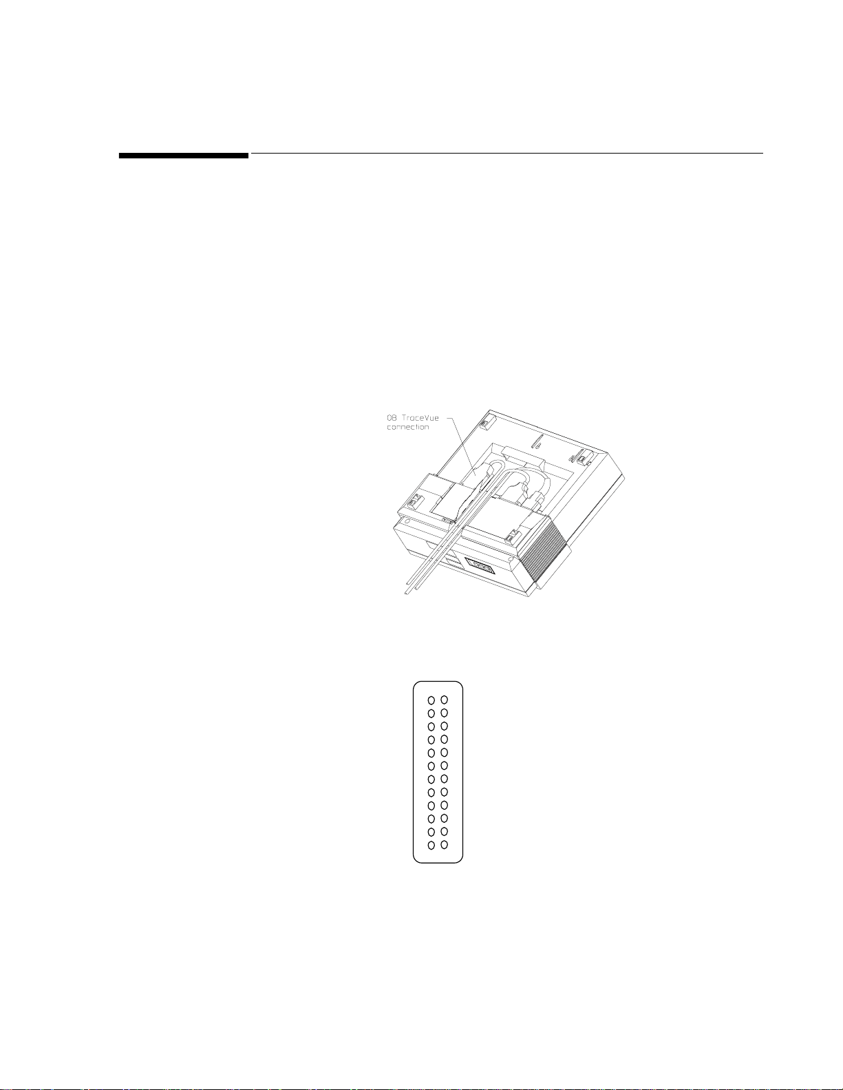
M1351A/M1353A The M1351A and M1353A fetal monitors can be connected directly to the OB TraceVue
or other host system or PC using an RS232 connector cable. The link requires a 24 pin to 9
pin adapter cable (you can use the preconfigured adapter cable, M1380-61613). This cable
connects to the fetal monitor with a 24 pin connector (do not use the 9 pin connector!).
Figure 1-1 M1351A/M1353A showing connecting cable to OB TraceVue
The pin allocation for the RS232 connecting cable is shown below:
13
1
14
2
15
3
16
4
17
5
18
6
19
7
Pin 8 RXD Input
Pin 9 TXD Output
20
8
21
9
22
10
23
11
24
12
Pin 24 Signal Ground
Figure 1-2 RS232 Cable Pin Allocation for the M1351A/M1353A to
Host System Connection
Hardware Configuration 3
Interface Connections
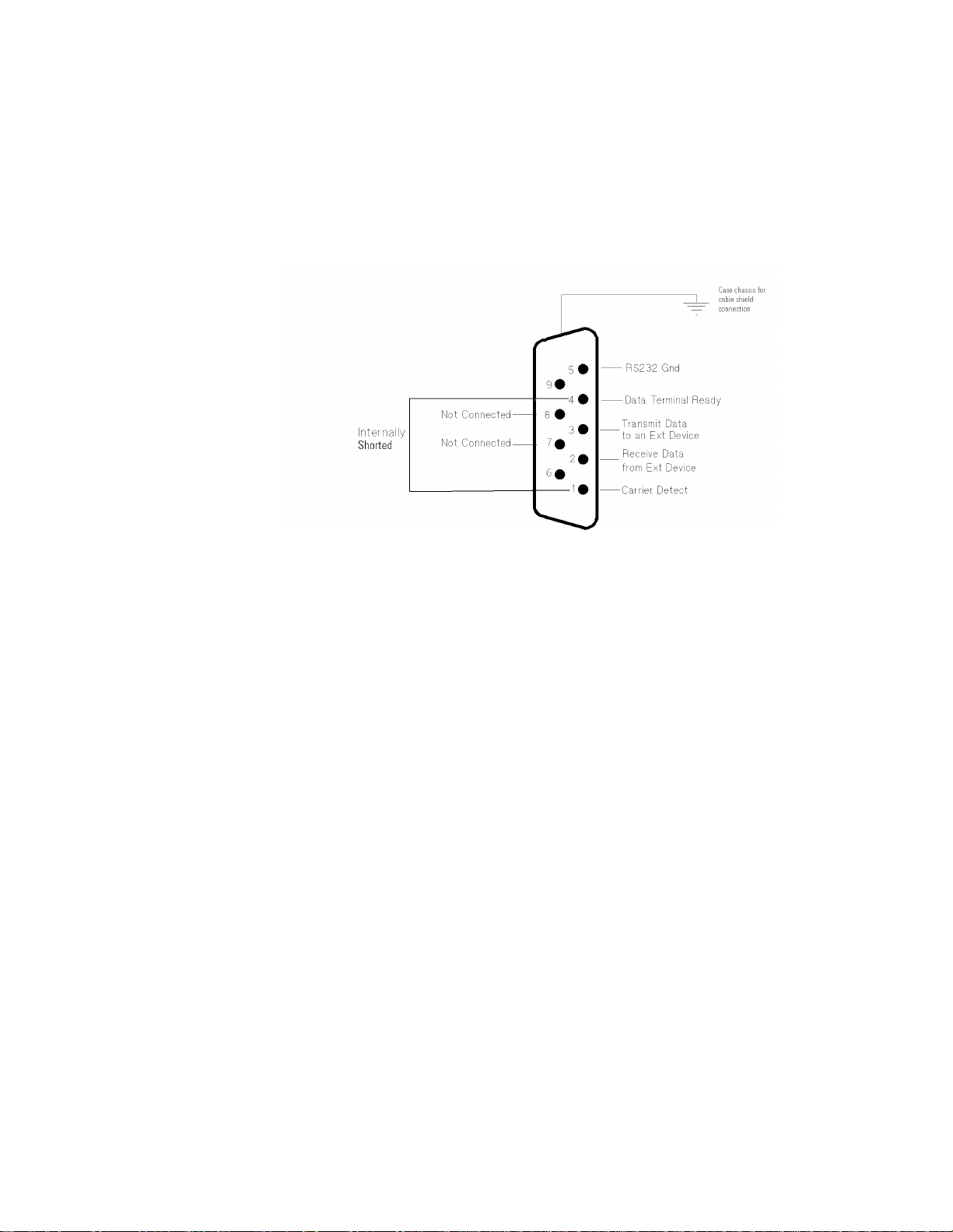
M1350 A/B/C The RS232 link between th e Series 50 A/B /C f etal/m aternal monitors
(M1350 A/B/C) and the PC or host system, for examp le OB TraceVue, uses a 9 pin t o 9 pin
connection. There is a preconfigured cable available (M
1380-61612). On the fetal monitor
side it connects to the Tele/Sys IF port (see Figure 1-5). Figure 1-3 shows the pin allocati on
for the connection.
Figure 1-3 M1350 A/B/C RS232 System Connector Pin Allocation
4 Hardware Configuration
RS422 Interface
Interface Connections
M1351A/M1353A
and M1350 A/B/C
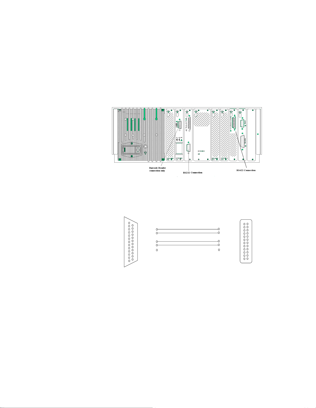
The Series 50 fetal monitors can be connected to a host system using the RS42 2 interface. If
you are connecting the M1350A or M1351A/M1353A to a host system or PC you will need
option #J12.
Figure 1-4 shows the location of the RS422 connection on the M1350 A/B/C fetal monitor.
Figure 1-4 M1350 A/B/C Interface Connections
The pin allocation for the RS422 interface signals is shown in Figure 1-5.
Computer
1
2
3
4
5
6
7
8
9
10
11
12
13
14
15
16
17
18
19
20
21
22
23
24
25
IN+ pin 18
IN- pin 3
OUT+ pin 10
OUT- pin 9
Pin 7
RS422
NOT CONNECTED
Pin 3 OUT+
Pin 15 OUT-
Pin17 IN+
Pin 18 IN-
Pin 12 GND
Shield
Fetal Monitor
13
1
14
2
15
3
16
4
17
5
18
6
19
7
20
8
21
9
22
10
23
11
24
12
Figure 1-5 PC to M1350 A/B/C RS422 Cable Connection
Hardware Configuration 5

Communication Summary
Communication Summary
The following is a summary of the protocol settings and parameters:
n
The communication is based on a serial connection, for example RS232 or RS422,
without handshake signals (uses only TxD/RxD).
n
The baudrate is 1200 Baud.
n
Data is sent using 1 start bit, 8 data bits, and 1 stop bit. No parity is used.
n
Data is sent within blocks. These blocks have a CRC-16 code appended to detect
transmission errors.
n
If a data block cannot be received correctly (as detected by the CRC-16 code), it will
not be retransmitted and must be ignored by the receiver.
n
When a word value is transmitted, the most significant byte (MSB ) is always sent first.
n
Unknown data blocks are ignored, thus introducing new data blocks in the future does
not disturb the receiver.
n
The maximum response time of the fetal monitor to a request depends on:
n
For ID-Code, CTG-Package:
Transfer time of request
+ 250 msec (max.)
+ rest time of an already started block
+ transfer time of the data-package
n
For other packages:
Transfer time of request
+ 500 msec (max.)
+ rest time of an already started block
+ transfer time of the data-package
Note Some functionality may not be implemented in a specific device (monitor or system). This is
independent of the protocol revision.
6 Hardware Configuration

Introduction
The Fetal Monitor connection is defined on three Data Protocol layers:
n
The Physical Layer.
n
The Data Link Layer.
n
The Application Layer.
This chapter describes the data link and application layers of the connection between the
fetal monitor and the host system. The physical layer is described in Chapter 1.
The Data Link Layer
The data link layer is responsible for the correct transmission of data blocks. It ensures the
data that is accepted at the receiver is correct. However it does not tell the transmitter that
the data is received correctly.
2
Fet al Monitor Connection
In order to achieve 8 bit data transparent trans mission, it is necessary to d efine a data linkage
escape character (DLE). This DLE character announces that the following byte is a special
block control character. If <DLE> occurs in the data stream, it will be replaced by a
<DLE><DLE> sequence to change the control character meaning to a normal character
value. Nevertheless, avoid having the <DLE> character sequence as a typical value in
frequently used data, because that increases the load on the connection.
A data block that is to be sent to the communication partner is surrounded by a block-start
and a block-end. The start block is defined as <DLE><STX> and the end block is
<DLE><ETX>. Following the block, a 2 byte CCITT CRC-16 code is sent to verify the
total block. For a description of the CRC mechanism see Chapter 4.
It is explicitly allowed that data is sent after <DLE><ETX> and before <DLE><STX> and
that data is discarded by the protocol.
The following rules apply to the data blocks:
n
If the CRC cannot be received correctly, the data block is discarded.
n
If a start of block is recognized before an end of block was received, the incomplete
block is discarded and the new block accepted.
Fetal Monitor Connection 7
The Application Layer
<DLE> <STX> ... Block data ... <DLE> <ETX> <CRC> <CRC>
Start of Block Data End of Block CCITT CRC
Table 2-1 Data Block Structure in the data link layer
The second item also means that the transmitter can stop the transmission of a block at
anytime, and start a new block; for example, to send a very urgent failure message.
Problems can occur if a transmitted message is interrupted directly after the <DLE><ETX>
sequence, (that is, within the CRC bytes). These bytes ar e read without in terpreting <DLE>
codes. The sender should, therefore, send two arbitrary bytes that do not contain one of the
special characters described in Table 2-2, for example, two zero-bytes. After thes e two bytes
a new block can be started and will be safely recognized.
It is assumed that data transmission errors are very rare, therefore, blocks that are incorrectly
received are not repeated.
Special Function Characters
The special function characters of the Series 50 Digital System Protocol are coded as listed
in Table 2-2. You should avoid using these character sequences in other functions.
Table 2-2 Special Function Characters
Character Hex Code Description
<DLE>
<STX>
<ETX>
The Application Layer
The application layer describes the data formats as they should be interpreted by the
applications that communicate with each other. The data is embedded in the structure
described in The Data Link Layer on page 2-7. Generally, a data block has the structure
shown in the following table:
10h
02h
03h
Data linkage escape
Start of text
End of text
Table 2-3 General Data Block Structure
Data Block Type Data...
8 Fetal Monitor Connection
char 0... 511 Byte

Data Block Overview
Introduction
This chapter provides an overview of t he indivi d ual dat a bl ocks. It also gives you a detai led
description of each block and tells you how to initiate transmission.
Data Block Overview
T able 3-1 indicates whether a data block can be transmitted from the host system to the fetal
monitor or from the fetal monitor to the host system. (Note: in this table FM=fetal monitor.)
Table 3-1 Data Block Overview (alphabetically sorted)
3
Type Function
C CTG Data Block * * * Be careful in auto
F Failures * * *
G Go (enter auto) * * * Start auto-send CTG
H Halt * * * Stop auto-send mode
I ID-code * * * Also sent by FM on
M Message block * * * Event messages, eg .
N Note * * * * Async., both
P NIBP (Blood Pressure) * * * Maternal external BP
SSpO
(oxygen sat.) * * * Maternal oxyge n
2
Used in direction
FM->Host Host->FM A.01.01 A.02.00
Available with
revision
Comments
mode!
data
power on
alarm ack. marker
directions
saturation
T Temperature * * * Maternal temperature
V Change protocol version * * Async. request
? Request data * * * Request an y of the
messages listed above
Rev. A.02.00 is required for FSpO
(M1350C only). See page 17 for more details.
2
Data Block Overview 9
 Loading...