

Philips 42PFL6158K/12, 42PFL7108K/12, 42PFL6158S/12, 40PFL8008S/60, 42PFL6188K/12 Service Manual
...
Colour Television Chassis
QFU1.2E
LA
Contents Page
1. Revision List 2
2. Technical Specs, Diversity, and Connections 2
3. Precautions, Notes, and Abbreviation List 7
4. Mechanical Instructions 11
5. Service Modes, Error Codes, and Fault Finding 20
6. Alignments 40
7. Circuit Descriptions 45
8. IC Data Sheets 47
9. Block Diagrams 49
10. Circuit Diagrams and PWB Layouts Drawing PWB
310431366124 SSB
59
99-100
310431366185 SSB 101
141-142
310431366186 SSB 143
183-184
C 310431366652 Amplifier panel 185
272217190763, 272217190764, 272217190766
Keyboard Control Module 187
282206502664, 282206502665, 820400159661

Revision List
EN 2 QFU1.2E LA1.
1. Revision List
Manual xxxx xxx xxxx.0
• First release.
Manual xxxx xxx xxxx.1
• Chapter 2: Table 2-1
updated (added CTNs).
• Chapter 4: added additional Ambilight unit handling info;
see section 4.3.2
.
Manual xxxx xxx xxxx.2
• Chapter 2: Table 2-1
updated (added CTNs).
Manual xxxx xxx xxxx.3
• Chapter 2: Table 2-1
updated (added CTNs).
• Chapter 6: added white tone values; see section 6.3.1
.
Manual xxxx xxx xxxx.4
• Chapter 2: Table 2-1
updated (added CTNs).
• Chapter 4: updated and added cable wiring (added CTNs).
• Chapter 6: added white tone values (added CTNs).
• Chapter 9: added wiring diagrams (added CTNs).
• Chapter 10: added schematics (AL).
• Chapter 11: added styling sheets (added CTNs).
2. Technical Specs, Diversity, and Connections
Index of this chapter:
2.1
Technical Specifications
2.2 Directions for Use
2.3 Connections
2.4 Chassis Overview
Notes:
• Figures can deviate due to the different set executions.
• Specifications are indicative (subject to change).
2.1 Technical Specifications
For on-line product support please use the CTN links in Table
2-1. Here is product information available, as well as getting
started, user manuals, frequently asked questions and
software & drivers.
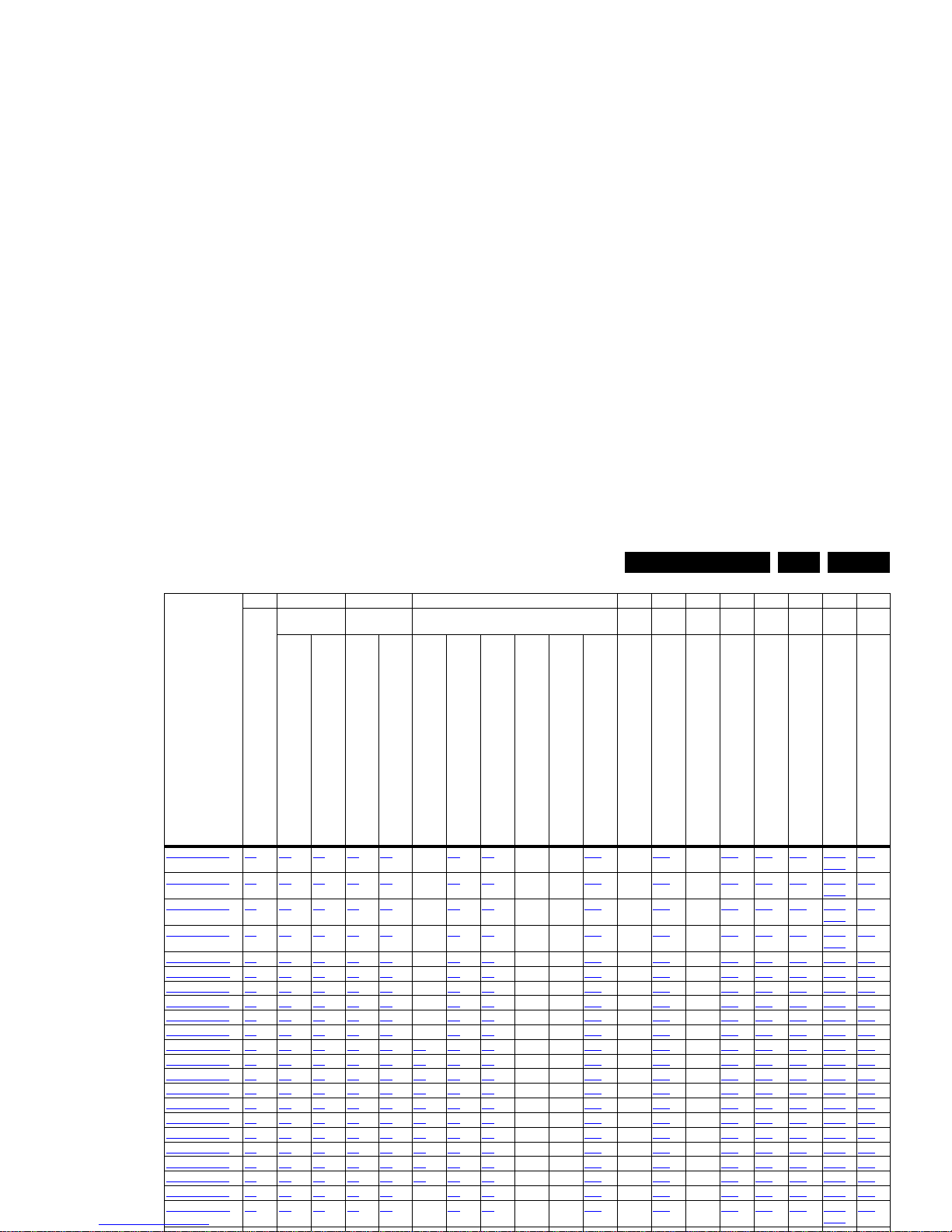
Table 2-1 Described Model Numbers and Diversity
2 4 7 9 10 11
Mechanics Descr. Block Diagrams
Schem
atics Styling
Technical Specs, Diversity, and Connections
EN 3QFU1.2E LA 2.
42PFL7108K/12 2.3 4-4 4.3 7.2 7.3 - 9.9 9.9 - - 9.10 - 10.2 - 10.5 10.7 10.9 10.11
10.12
11.2
42PFL7108S/12 2.3 4-4 4.3 7.2 7.3 - 9.9 9.9 - - 9.10 - 10.2 - 10.5 10.7 10.9 10.11
10.12
11.2
42PFL7108S/60 2.3 4-4 4.3 7.2 7.3 - 9.9 9.9 - - 9.10 - 10.2 - 10.5 10.7 10.9 10.11
10.12
11.2
42PFL7108T/12 2.3 4-4 4.3 7.2 7.3 - 9.9 9.9 - - 9.10 - 10.2 - 10.5 10.7 10.9 10.11
10.12
11.2
46PDL8908S/12 2.3 4-7 4.3 7.2 7.3 - 9.9 9.9 - - 9.10 - 10.1 - 10.5 10.8 10.9 10.12 11.4
46PDL8908S/60 2.3 4-7 4.3 7.2 7.3 - 9.9 9.9 - - 9.10 - 10.1 - 10.5 10.8 10.9 10.12 11.4
46PFL8008K/12 2.3 4-5 4.3 7.2 7.3 - 9.9 9.9 - - 9.10 - 10.1 - 10.5 10.7 10.9 10.15 11.3
46PFL8008S/12 2.3 4-5 4.3 7.2 7.3 - 9.9 9.9 - - 9.10 - 10.1 - 10.5 10.7 10.9 10.15 11.3
46PFL8008S/60 2.3 4-5 4.3 7.2 7.3 - 9.9 9.9 - - 9.10 - 10.1 - 10.5 10.7 10.9 10.15 11.3
46PFL8008S/98 2.3 4-5 4.3 7.2 7.3 - 9.9 9.9 - - 9.10 - 10.1 - 10.5 10.7 10.9 10.15 11.3
47PFL6008H/12 2.3 4-3 4.3 7.2 7.3 9.2 9.9 9.9 - - 9.10 - 10.2 - 10.5 10.7 10.9 10.15 11.1
47PFL6008K/12 2.3 4-3 4.3 7.2 7.3 9.2 9.9 9.9 - - 9.10 - 10.2 - 10.5 10.7 10.9 10.15 11.1
47PFL6008S/12 2.3 4-3 4.3 7.2 7.3 9.2 9.9 9.9 - - 9.10 - 10.2 - 10.5 10.7 10.9 10.15 11.1
47PFL6008S/60 2.3 4-3 4.3 7.2 7.3 9.2 9.9 9.9 - - 9.10 - 10.2 - 10.5 10.7 10.9 10.15 11.1
47PFL6158K/12 2.3 4-3 4.3 7.2 7.3 9.2 9.9 9.9 - - 9.10 - 10.2 - 10.5 10.7 10.9 10.15 11.1
47PFL6158S/12 2.3 4-3 4.3 7.2 7.3 9.2 9.9 9.9 - - 9.10 - 10.2 - 10.5 10.7 10.9 10.15 11.1
47PFL6188K/12 2.3 4-3 4.3 7.2 7.3 9.2 9.9 9.9 - - 9.10 - 10.2 - 10.5 10.7 10.9 10.15 11.1
47PFL6188S/12 2.3 4-3 4.3 7.2 7.3 9.2 9.9 9.9 - - 9.10 - 10.2 - 10.5 10.7 10.9 10.15 11.1
47PFL6198K/12 2.3 4-3 4.3 7.2 7.3 9.2 9.9 9.9 - - 9.10 - 10.2 - 10.5 10.7 10.9 10.15 11.1
47PFL6678K/12 2.3 4-3 4.3 7.2 7.3 9.2 9.9 9.9 - - 9.10 - 10.2 - 10.5 10.7 10.9 10.15 11.1
47PFL6678S/12 2.3 4-3 4.3 7.2 7.3 - 9.9 9.9 - - 9.10 - 10.2 - 10.5 10.7 10.9 10.15 11.1
47PFL7008H/12 2.3 4-4 4.3 7.2 7.3 - 9.9 9.9 - - 9.10 - 10.2 - 10.5 10.7 10.9 10.12
10.13
11.2
CTN
24 7 9 10 11
Connection Overview
Mechanics Descr. Block Diagrams
Schem
atics Styling
Wire Dressing
Assembly Removal
Power Supply
General Power Architecture
Wiring Diagram
Video
Audio
Control & Clock
I2C
Supply lines
Power Supply
SSB
Amplifier control module
(Keyboard Control Module)
(Wireless LAN USB, Light Sensor, IR/LED Module)
(Sensor Module)
(AmbiLight)
Sheet

Technical Specs, Diversity, and Connections
EN 4 QFU1.2E LA2.
55PFL6188S/12 2.3 4-3 4.3 7.2 7.3 9.3 9.9 9.9 - - 9.10 - 10.2 - 10.5 10.8 10.9 10.16 11.5
55PFL6198K/12 2.3 4-3 4.3 7.2 7.3 9.3 9.9 9.9 - - 9.10 - 10.2 - 10.5 10.8 10.9 10.16 11.5
55PFL6678K/12 2.3 4-3 4.3 7.2 7.3 9.3 9.9 9.9 - - 9.10 - 10.2 - 10.5 10.8 10.9 10.16 11.5
55PFL6678S/12 2.3 4-3 4.3 7.2 7.3 9.3 9.9 9.9 - - 9.10 - 10.2 - 10.5 10.8 10.9 10.16 11.5
55PFL7008H/12 2.3 4-8 4.3 7.2 7.3 9.4 9.9 9.9 - - 9.10 - 10.2 - 10.5 10.8 10.9 10.13
10.10
10.11
11.6
55PFL7008K/12 2.3 4-8 4.3 7.2 7.3 9.4 9.9 9.9 - - 9.10 - 10.2 - 10.5 10.8 10.9 10.13
10.10
10.11
11.6
55PFL7008S/12 2.3 4-8 4.3 7.2 7.3 9.4 9.9 9.9 - - 9.10 - 10.2 - 10.5 10.8 10.9 10.13
10.10
10.11
11.6
55PFL7008S/60 2.3 4-8 4.3 7.2 7.3 9.4 9.9 9.9 - - 9.10 - 10.2 - 10.5 10.8 10.9 10.13
10.10
10.11
11.6
55PFL7108H/12 2.3 4-8 4.3 7.2 7.3 9.4 9.9 9.9 - - 9.10 - 10.2 - 10.5 10.8 10.9 10.13
10.10
10.11
11.6
55PFL7108K/12 2.3 4-8 4.3 7.2 7.3 9.4 9.9 9.9 - - 9.10 - 10.2 - 10.5 10.8 10.9 10.13
10.10
10.11
11.6
55PFL7108S/12 2.3 4-8 4.3 7.2 7.3 9.4 9.9 9.9 - - 9.10 - 10.2 - 10.5 10.8 10.9 10.13
10.10
10.11
11.6
55PFL7108S/60 2.3 4-8 4.3 7.2 7.3 9.4 9.9 9.9 - - 9.10 - 10.2 - 10.5 10.8 10.9 10.13
10.10
10.11
11.6
55PFL8008K/12 2.3 4-9 4.3 7.2 7.3 - 9.9 9.9 - - 9.10 - 10.2 - 10.5 10.8 10.9 10.15 11.7
CTN
2 4 7 9 10 11
Connection Overview
Mechanics Descr. Bl o ck Diagrams
Schem
atics Styling
Wire Dressing
Assembly Removal
Power Supply
General Power Architecture
Wiring Diagram
Video
Audio
Control & Clock
I2C
Supply lines
Power Supply
SSB
Amplifier control module
(Keyboard Control Module)
(Wireless LAN USB, Light Sensor, IR/LED Module)
(Sensor Module)
(AmbiLight)
Sheet
Technical Specs, Diversity, and Connections
EN 5QFU1.2E LA 2.
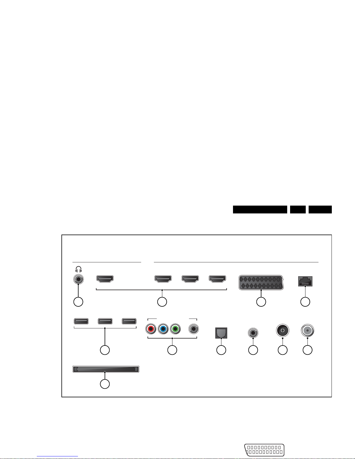
2.3 Connections
Figure 2-1 Connection overview
Note: The following connector colour abbreviations are used
(acc. to DIN/IEC 757): Bk= Black, Bu= Blue, Gn= Green, Gy=
Grey, Rd= Red, Wh= White, Ye= Yellow.
2.3.1 Connections
20 - Ground Gnd H
3 - Video RGB - In, CVBS - In/Out, Audio - In/Out
Connections
Side Rear
HDMI 4
USB USB USB
COMMON INTERFACE
HDMI 1
ARCARC ARC ARC
HDMI 2 HDMI 3 SCART
NETWORK
AUDIO OUT
ANTENNA
AUDIO IN
L / ROPTICAL
Y Pb Pr - L R
SATELLITE
19370_062_130201.eps
130404
10
5 76 8
321 4
9
11
(optional)
20
2

Technical Specs, Diversity, and Connections
EN 6 QFU1.2E LA2.
4 - RJ45: Ethernet
Figure 2-4 Ethernet connector
1 -TD+ Transmit signal k
2 -TD- Transmit signal k
3 -RD+ Receive signal j
4 -CT Centre Tap: DC level fixation
5 -CT Centre Tap: DC level fixation
6 -RD- Receive signal j
7 -GND Gnd H
8 -GND Gnd H
5 - USB2.0
Figure 2-5 USB (type A)
1-+5V k
2 -Data (-) jk
3 -Data (+) jk
4 -Ground Gnd H
6 - Cinch: Video YPbPr - In, Audio - In
Gn - Video Y 1 V
PP
/ 75 ohm jq
Bu -Video Pb 0.7 V
PP
/ 75 ohm jq
Rd -Video Pr 0.7 V
PP
/ 75 ohm jq
Rd -Audio - R 0.5 V
RMS
/ 10 kohm jq
Wh -Audio - L 0.5 V
RMS
/ 10 kohm jq
7 - Cinch: S/PDIF - Out
Bk -Coaxial 0.4 - 0.6V
PP
/ 75 ohm kq
8 - Cinch: Audio - In (VGA/DVI)
Rd -Audio R 0.5 V
RMS
/ 10 kohm jq
Wh -Audio L 0.5 V
RMS
/ 10 kohm jq
9 - Aerial - In
- -IEC-type (EU) Coax, 75 ohm D
10 - Common Interface
68p- See Figure 10-1-35
B06I, CI conditional access jk
11 - SAT - In (optional)
- -F-type Coax, 75 ohm D
2.4 Chassis Overview
Refer to chapter 9. Block Diagrams for PWB/CBA locations.
10000_025_090121.eps
120320
1 2 3 4
10000_022_090121.eps
090121

Precautions, Notes, and Abbreviation List
EN 7QFU1.2E LA 3.
3. Precautions, Notes, and Abbreviation List
Index of this chapter:
3.1
Safety Instructions
3.2 Warnings
3.3 Notes
3.4 Abbreviation List
3.1 Safety Instructions
Safety regulations require the following during a repair:
• Connect the set to the Mains/AC Power via an isolation
transformer (> 800 VA).
• Replace safety components, indicated by the symbol h,
only by components identical to the original ones. Any
other component substitution (other than original type) may
increase risk of fire or electrical shock hazard.
Safety regulations require that after a repair, the set must be
returned in its original condition. Pay in particular attention to
the following points:
• Route the wire trees correctly and fix them with the
mounted cable clamps.
• Check the insulation of the Mains/AC Power lead for
external damage.
• Check the strain relief of the Mains/AC Power cord for
proper function.
• Check the electrical DC resistance between the Mains/AC
Power plug and the secondary side (only for sets that have
a Mains/AC Power isolated power supply):
1. Unplug the Mains/AC Power cord and connect a wire
between the two pins of the Mains/AC Power plug.
2. Set the Mains/AC Power switch to the “on” position
(keep the Mains/AC Power cord unplugged!).
3. Measure the resistance value between the pins of the
Mains/AC Power plug and the metal shielding of the
tuner or the aerial connection on the set. The reading
should be between 4.5 M and 12 M.
4. Switch “off” the set, and remove the wire between the
two pins of the Mains/AC Power plug.
• Check the cabinet for defects, to prevent touching of any
inner parts by the customer.
3.2 Warnings
3.3.2 Schematic Notes
• All resistor values are in ohms, and the value multiplier is
often used to indicate the decimal point location (e.g. 2K2
indicates 2.2 k).
• Resistor values with no multiplier may be indicated with
either an “E” or an “R” (e.g. 220E or 220R indicates 220 ).
• All capacitor values are given in micro-farads (10
-6
),
nano-farads (n 10
-9
), or pico-farads (p 10
-12
).
• Capacitor values may also use the value multiplier as the
decimal point indication (e.g. 2p2 indicates 2.2 pF).
• An “asterisk” (*) indicates component usage varies. Refer
to the diversity tables for the correct values.
• The correct component values are listed on the Philips
Spare Parts Web Portal.
3.3.3 Spare Parts
For the latest spare part overview, consult your Philips Spare
Part web portal.
3.3.4 BGA (Ball Grid Array) ICs
Introduction
For more information on how to handle BGA devices, visit this
URL: http://www.atyourservice-magazine.com
. Select
“Magazine”, then go to “Repair downloads”. Here you will find
Information on how to deal with BGA-ICs.
BGA Temperature Profiles
For BGA-ICs, you must use the correct temperature-profile.
Where applicable and available, this profile is added to the IC
Data Sheet information section in this manual.
3.3.5 Lead-free Soldering
Due to lead-free technology some rules have to be respected
by the workshop during a repair:
• Use only lead-free soldering tin. If lead-free solder paste is
required, please contact the manufacturer of your soldering

Precautions, Notes, and Abbreviation List
EN 8 QFU1.2E LA3.
result in sets which have the same CTN (Commercial Type
Number; e.g. 28PW9515/12) but which have a different B.O.M.
number.
By looking at the third digit of the serial number, one can
identify which B.O.M. is used for the TV set he is working with.
If the third digit of the serial number contains the number “1”
(example: AG1B033500001), then the TV set has been
manufactured according to B.O.M. number 1. If the third digit is
a “2” (example: AG2B0335000001), then the set has been
produced according to B.O.M. no. 2. This is important for
ordering the correct spare parts!
For the third digit, the numbers 1...9 and the characters A...Z
can be used, so in total: 9 plus 26= 35 different B.O.M.s can be
indicated by the third digit of the serial number.
Identification: The bottom line of a type plate gives a 14-digit
serial number. Digits 1 and 2 refer to the production centre (e.g.
SN is Lysomice, RJ is Kobierzyce), digit 3 refers to the B.O.M.
code, digit 4 refers to the Service version change code, digits 5
and 6 refer to the production year, and digits 7 and 8 refer to
production week (in example below it is 2010 week 10 / 2010
week 17). The 6 last digits contain the serial number.
6 = play 16 : 9 format, 12 = play 4 : 3
format
AARA Automatic Aspect Ratio Adaptation:
algorithm that adapts aspect ratio to
remove horizontal black bars; keeps
the original aspect ratio
ACI Automatic Channel Installation:
algorithm that installs TV channels
directly from a cable network by
means of a predefined TXT page
ADC Analogue to Digital Converter
AFC Automatic Frequency Control: control
signal used to tune to the correct
frequency
AGC Automatic Gain Control: algorithm that
controls the video input of the feature
box
AM Amplitude Modulation
AP Asia Pacific
AR Aspect Ratio: 4 by 3 or 16 by 9
ASF Auto Screen Fit: algorithm that adapts
aspect ratio to remove horizontal black
bars without discarding video
information
ATSC Advanced Television Systems
Committee, the digital TV standard in
the USA
ATV See Auto TV
Auto TV A hardware and software control
system that measures picture content,
and adapts image parameters in a
dynamic way
AV External Audio Video
AVC Audio Video Controller
AVIP Audio Video Input Processor
B/G Monochrome TV system. Sound
carrier distance is 5.5 MHz
BDS Business Display Solutions (iTV)
BLR Board-Level Repair
BTSC Broadcast Television Standard
Committee. Multiplex FM stereo sound
system, originating from the USA and
used e.g. in LATAM and AP-NTSC
countries

Precautions, Notes, and Abbreviation List
EN 9QFU1.2E LA 3.
DNR Digital Noise Reduction: noise
reduction feature of the set
DRAM Dynamic RAM
DRM Digital Rights Management
DSP Digital Signal Processing
DST Dealer Service Tool: special remote
control designed for service
technicians
DTCP Digital Transmission Content
Protection; A protocol for protecting
digital audio/video content that is
traversing a high speed serial bus,
such as IEEE-1394
DVB-C Digital Video Broadcast - Cable
DVB-T Digital Video Broadcast - Terrestrial
DVD Digital Versatile Disc
DVI(-d) Digital Visual Interface (d= digital only)
E-DDC Enhanced Display Data Channel
(VESA standard for communication
channel and display). Using E-DDC,
the video source can read the EDID
information form the display.
EDID Extended Display Identification Data
(VESA standard)
EEPROM Electrically Erasable and
Programmable Read Only Memory
EMI Electro Magnetic Interference
EPG Electronic Program Guide
EPLD Erasable Programmable Logic Device
EU Europe
EXT EXTernal (source), entering the set by
SCART or by cinches (jacks)
FDS Full Dual Screen (same as FDW)
FDW Full Dual Window (same as FDS)
FLASH FLASH memory
FM Field Memory or Frequency
Modulation
FPGA Field-Programmable Gate Array
FTV Flat TeleVision
Gb/s Giga bits per second
G-TXT Green TeleteXT
H H_sync to the module
HD High Definition
HDD Hard Disk Drive
The SDI signal is self-synchronizing,
uses 8 bit or 10 bit data words, and has
a maximum data rate of 270 Mbit/s,
with a minimum bandwidth of 135
MHz.
iTV Institutional TeleVision; TV sets for
hotels, hospitals etc.
LS Last Status; The settings last chosen
by the customer and read and stored
in RAM or in the NVM. They are called
at start-up of the set to configure it
according to the customer's
preferences
LATAM Latin America
LCD Liquid Crystal Display
LED Light Emitting Diode
L/L' Monochrome TV system. Sound
carrier distance is 6.5 MHz. L' is Band
I, L is all bands except for Band I
LPL LG.Philips LCD (supplier)
LS Loudspeaker
LVDS Low Voltage Differential Signalling
Mbps Mega bits per second
M/N Monochrome TV system. Sound
carrier distance is 4.5 MHz
MHEG Part of a set of international standards
related to the presentation of
multimedia information, standardised
by the Multimedia and Hypermedia
Experts Group. It is commonly used as
a language to describe interactive
television services
MIPS Microprocessor without Interlocked
Pipeline-Stages; A RISC-based
microprocessor
MOP Matrix Output Processor
MOSFET Metal Oxide Silicon Field Effect
Transistor, switching device
MPEG Motion Pictures Experts Group
MPIF Multi Platform InterFace
MUTE MUTE Line
MTV Mainstream TV: TV-mode with
Consumer TV features enabled (iTV)
NC Not Connected

Precautions, Notes, and Abbreviation List
EN 10 QFU1.2E LA3.
PDP Plasma Display Panel
PFC Power Factor Corrector (or Pre-
conditioner)
PIP Picture In Picture
PLL Phase Locked Loop. Used for e.g.
FST tuning systems. The customer
can give directly the desired frequency
POD Point Of Deployment: a removable
CAM module, implementing the CA
system for a host (e.g. a TV-set)
POR Power On Reset, signal to reset the uP
PSDL Power Supply for Direct view LED
backlight with 2D-dimming
PSL Power Supply with integrated LED
drivers
PSLS Power Supply with integrated LED
drivers with added Scanning
functionality
PTC Positive Temperature Coefficient,
non-linear resistor
PWB Printed Wiring Board (same as “PCB”)
PWM Pulse Width Modulation
QRC Quasi Resonant Converter
QTNR Quality Temporal Noise Reduction
QVCP Quality Video Composition Processor
RAM Random Access Memory
RGB Red, Green, and Blue. The primary
color signals for TV. By mixing levels
of R, G, and B, all colors (Y/C) are
reproduced.
RC Remote Control
RC5 / RC6 Signal protocol from the remote
control receiver
RESET RESET signal
ROM Read Only Memory
RSDS Reduced Swing Differential Signalling
data interface
R-TXT Red TeleteXT
SAM Service Alignment Mode
S/C Short Circuit
SCART Syndicat des Constructeurs
d'Appareils Radiorécepteurs et
Téléviseurs
SCL Serial Clock I
2
C
SWAN Spatial temporal Weighted Averaging
Noise reduction
SXGA 1280 × 1024
TFT T hin Film Transistor
THD Total Harmonic Distortion
TMDS Transmission Minimized Differential
Signalling
TS Transport Stream
TXT TeleteXT
TXT-DW Dual Window with TeleteXT
UI User Interface
uP Microprocessor
UXGA 1600 × 1200 (4:3)
V V-sync to the module
VESA Video Electronics Standards
Association
VGA 640 × 480 (4:3)
VL Variable Level out: processed audio
output toward external amplifier
VSB Vestigial Side Band; modulation
method
WYSIWYR What You See Is What You Record:
record selection that follows main
picture and sound
WXGA 1280 × 768 (15:9)
XTAL Quartz crystal
XGA 1024 × 768 (4:3)
Y Luminance signal
Y/C Luminance (Y) and Chrominance (C)
signal
YPbPr Component video. Luminance and
scaled color difference signals (B-Y
and R-Y)
YUV Component video

Mechanical Instructions
EN 11QFU1.2E LA 4.
4. Mechanical Instructions
Index of this chapter:
4.1
Cable Dressing-
4.2 Service Positions
4.3 Assy/Panel Removal
4.4 Set Re-assembly
Notes:
• Figures below can deviate slightly from the actual situation,
due to the different set executions.
4.1 Cable Dressing-
Figure 4-1 Cable dressing 40" 8000 series

Mechanical Instructions
EN 12 QFU1.2E LA4.
Figure 4-3 Cable dressing 42" - 47" - 55" - 60" 6000 series
19210_104_120516.eps
120516
Not available

Mechanical Instructions
EN 13QFU1.2E LA 4.
Figure 4-5 Cable dressing 46" 8000 series

Mechanical Instructions
EN 14 QFU1.2E LA4.
Figure 4-7 Cable dressing 46" - 55" 8000 Design series
19210_104_120516.eps
120516
Not available

Mechanical Instructions
EN 15QFU1.2E LA 4.
Figure 4-9 Cable dressing 55" 8000 series

Mechanical Instructions
EN 16 QFU1.2E LA4.
Figure 4-11 Cable dressing 60" 8000 series
19374_027_140110.eps
140110

Mechanical Instructions
EN 17QFU1.2E LA 4.
Figure 4-13 Cable dressing 65" 9000 series - Back cover
19374_029_140110.eps
140110

Mechanical Instructions
EN 18 QFU1.2E LA4.
Figure 4-15 Cable dressing 84" 9000 series - Back cover
4.2 Service Positions
For easy servicing of a TV set, the set should be put face down
on a soft flat surface, foam buffers or other specific workshop
tools. Ensure that a stable situation is created to perform
measurements and alignments. When using foam bars take
care that these always support the cabinet and never only the
display.
Caution: Failure to follow these guidelines can seriously
damage the display!
Ensure that ESD safe measures are taken.
4.3 Assy/Panel Removal
19374_031_140110.eps
140110
Mechanical Instructions
EN 19QFU1.2E LA 4.
Figure 4-17 Rear cover removal Ambilight models -2-
4.3.2 Ambilight units in Rear Cover
The Ambilight units are affixed in the rear cover and will selfdestruct upon removal.
Attention: it is of the utmost importance to remove all remains
of any adhesive that might be left on the inside of the rear
cover.
The new units come with double-sided adhesive tape. Ensure
a correct mounting to avoid uneven light emission of the units.
4.3.3 SSB
Refer to Figure 4-18
and Figure 4-19 for details.
Some SSBs have a dedicated LVDS connector, requiring
pressing two catches as indicated in the figure, before
removing the LVDS cable.
Figure 4-19 SSB LVDS connector catches (optional) -2-
4.4 Set Re-assembly
To re-assemble the whole set, execute all processes in reverse
order.
Notes:
• While re-assembling, make sure that all cables are placed
and connected in their original position.
• Pay special attention not to damage the EMC foams in the
set. Ensure that EMC foams are mounted correctly.
19370_081_130208.eps
130208
33
19222_001_120626.eps
120626
Click!
LVDS flat foil
Click!
Service Modes, Error Codes, and Fault Finding
EN 20 QFU1.2E LA5.
5. Service Modes, Error Codes, and Fault Finding
Index of this chapter:
5.1
Test Points
5.2 Service Modes
5.3 Start-up
5.4 Service Tools
5.5 Error Codes
5.6 The Blinking LED Procedure
5.7 Protections
5.8 Fault Finding and Repair Tips
5.9 Software Upgrading
5.1 Test Points
As most signals are digital, it will be difficult to measure
waveforms with a standard oscilloscope. However, several key
ICs are capable of generating test patterns, which can be
controlled via ComPair. In this way it is possible to determine
which part is defective.
Perform measurements under the following conditions:
• Service Default Mode.
• Video: Colour bar signal.
• Audio: 3 kHz left, 1 kHz right.
5.2 Service Modes
Service Default mode (SDM) and Service Alignment Mode
(SAM) offers several features for the service technician, while
the Customer Service Mode (CSM) is used for communication
between the call centre and the customer.
Note: For the new model range, a new remote control (RC) is
used with some renamed buttons. This has an impact on the
activation of the Service modes. For instance the old “MENU”
button is now called “HOME” (or is indicated by a “house” icon).
5.2.1 Service Default Mode (SDM)
Purpose
• To create a pre-defined setting, to get the same
measurement results as given in this manual.
• To override SW protections detected by the standby
processor and make the TV start up to the step just before
• Digital SDM: use the RC-transmitter and key in the code
“062593”, directly followed by the “MENU” (or "HOME")
button.
Note: It is possible that, together with the SDM, the main
menu will appear. To switch it “off”, push the “MENU” (or
"HOME") button again.
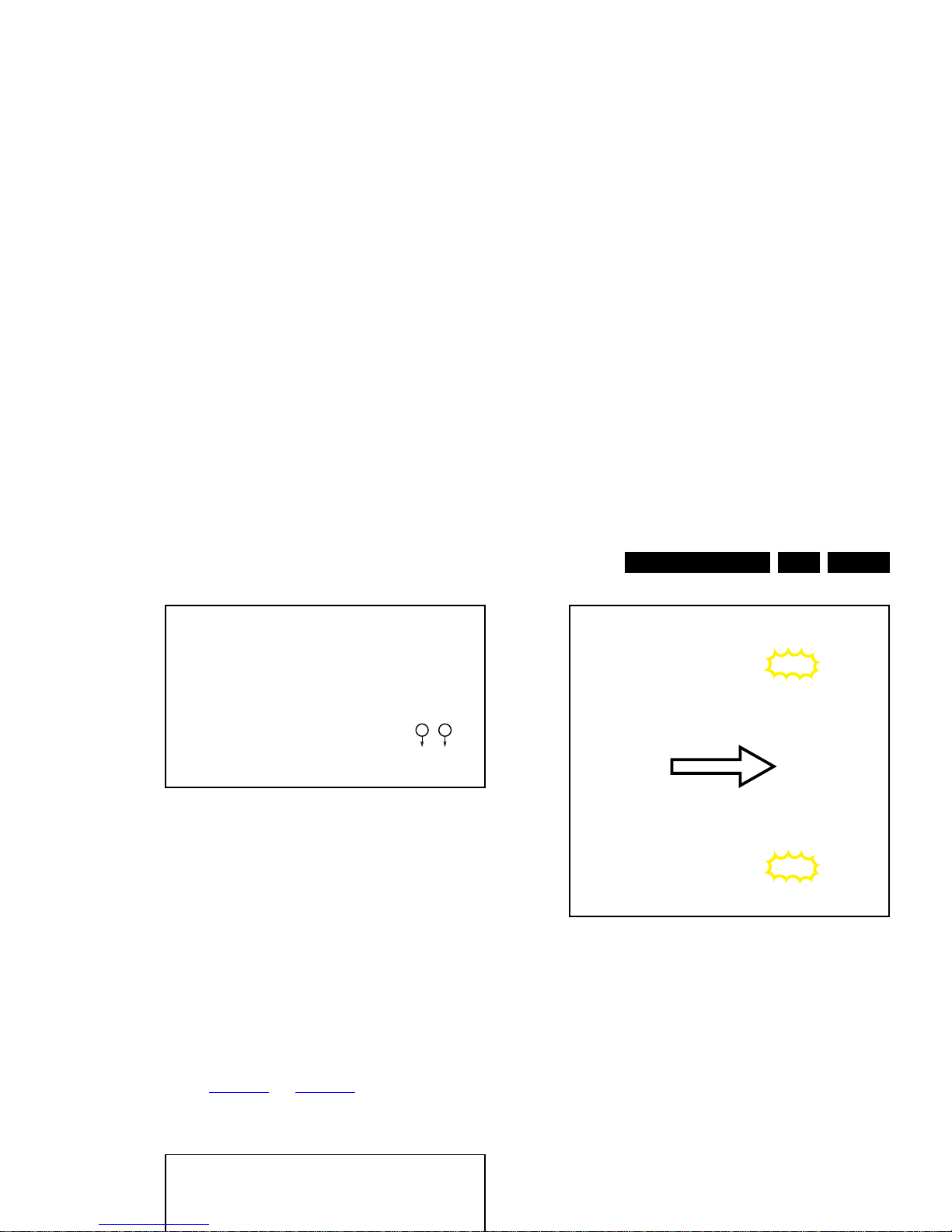
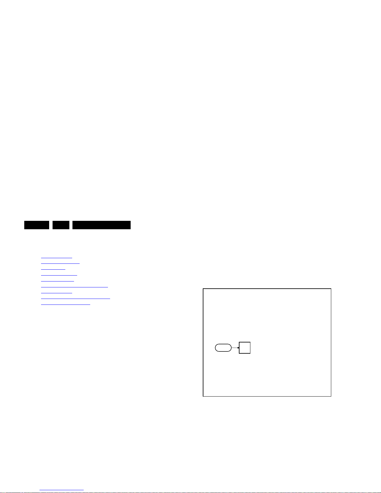
Figure 5-1 Service mode pad
After activating this mode, “SDM” will appear in the upper right
corner of the screen (when a picture is available).
How to Exit SDM
Use one of the following methods:
• Switch the set to STANDBY via the RC-transmitter.
• Via a standard customer RC-transmitter: key in “00”sequence.
5.2.2 Service Alignment Mode (SAM)
19370_061_130201.eps
130507
SDM

Service Modes, Error Codes, and Fault Finding
EN 21QFU1.2E LA 5.
be re-written to NVM. The update can be done via the
NVM editor available in SAM.
• Operation hours. Displays the accumulated total of
operation hours (not the standby hours). Every time the TV
is switched “on/off”, 0.5 hours is added to this number.
• Errors (followed by maximum 10 errors). The most recent
error is displayed at the upper left (for an error explanation
see section “5.5
Error Codes”).
• Reset Error Buffer. When “cursor right” (or “OK” button)
pressed here, followed by the “OK” button, the error buffer
is reset.
• Alignments. This will activate the “ALIGNMENTS” submenu. See Chapter 6.
Alignments.
• Options numbers. Extra features for Service. For more
info regarding option codes, see chapter 6.
Alignments.
Note that if the option code numbers are changed, these
have to be confirmed with pressing the “OK” button before
the options are stored, otherwise changes will be lost.
• Initialise NVM. The moment the processor recognizes a
corrupted NVM, the “initialise NVM” line will be highlighted.
Now, two things can be done (dependent of the service
instructions at that moment):
– Save the content of the NVM via ComPair for
development analysis, before initializing. This will give
the service department an extra possibility for
diagnosis (e.g. when Development asks for this).
– Initialise the NVM.
Note: When the NVM is corrupted, or replaced, there is a high
possibility that no picture appears because the display code is
not correct. So, before initializing the NVM via the SAM, a
picture is necessary and therefore the correct display option
has to be entered. Refer to Chapter 6.
Alignments for details.
To adapt this option, it’s advised to use ComPair (the correct
values for the options can be found in Chapter 6.
Alignments)
or a method via a standard RC (described below).
Changing the display option via a standard RC: Key in the
code “062598” directly followed by the “MENU” (or "HOME")
button and “XXX” (where XXX is the 3 digit decimal display
code as mentioned on the sticker in the set). Make sure to key
in all three digits, also the leading zero’s. If the above action is
successful, the front LED will go out as an indication that the
RC sequence was correct. After the display option is changed
• Test settings. For development purposes only.
• RF4CE pairing tables. Clear paired remote control. Repairing (coldboot of platform possibly needed) can be done
by pressing the red/blue hot keys simultaneously for a few
seconds.(be sure the distance between the remote control
and TV set RF4CE receiver is less then 30cm). Message
like “Pairing successful”, confirms the match-make.
• Development 1 file versions. Not useful for Service
purposes, this information is mainly used by the
development department.
• Development 2 file versions. Not useful for Service
purposes, this information is mainly used by the
development department.
• Upload to USB. To upload several settings from the TV to
an USB stick, which is connected to the SSB. The items are
“Personal settings”, “Option codes”, “Alignments”,
“Identification data” (includes the set type and prod code +
all 12NC like SSB, display, boards), “History list”. The “All”
item supports the upload of all several items at once.
A directory “repair\” will be created in the root of the
USB stick.
To upload the settings, select each item separately, press
“cursor right” (or the “OK” button), confirm with “OK” and
wait until the message “Done” appears. In case the
download to the USB stick was not successful, “Failure” will
be displayed. In this case, check if the USB stick is
connected properly and if the directory “repair” is present in
the root of the USB stick. Now the settings are stored onto
the USB stick and can be used to download into another TV
or other SSB. Uploading is of course only possible if the
software is running and preferably a picture is available.
This method is created to be able to save the customer’s
TV settings and to store them into another SSB.
Important remark : to upload the “channel list”, select
“Home” => “Setup” => “TV settings” => “General settings”
=> “Channel list copy” => “Copy to USB”.The procedure is
also described in the (electronic) user manual.
• Download from USB. To download several settings from
the USB stick to the TV, same way of working needs to be
followed as described in “Upload to USB”. The “All” item
supports to download all several items at once.
Important remark : to download the “channel list”, select
“Home” => “Setup” => “TV settings” => “General settings”
=> “Channel list copy” => “Copy to TV”. The procedure is

Service Modes, Error Codes, and Fault Finding
EN 22 QFU1.2E LA5.
5.2.3 Customer Service Mode (CSM)
Purpose
When a customer is having problems with his TV-set, he can
call his dealer or the Customer Helpdesk. The service
technician can then ask the customer to activate the CSM, in
order to identify the status of the set. Now, the service
technician can judge the severity of the complaint. In many
cases, he can advise the customer how to solve the problem,
or he can decide if it is necessary to visit the customer.
The CSM is a read only mode, therefore modifications in this
mode are not possible.
Provided CSM is activated, every menu from CSM can be used
as check for the back end chain video.So for all CSM content
displayed, it could be determined that the back end video chain
is working.
When CSM is activated and there is a USB stick connected to
the TV set, the software will dump the CSM content to the USB
stick.The file (CSM_model number_serial number.xml) will be
saved in the root of the USB stick. This info can be handy if no
information is displayed.
Additional in CSM mode (with USB stick connected), pressing
“OK” will create an extended CSM dump file on the USB stick.
This file (Extended_CSM_model number_serial number.xml)
contains:
• The normal CSM dump information,
• All items (from SAM “load to USB”, but in readable format),
• Operating hours,
• Error codes,
• SW/HW event logs.
To have fast feedback from the field, a flashdump can be
requested by development. When in CSM, push the “red”
button and key in serial digits ‘2679’ (same keys to form the
word ‘COPY’ with a cellphone). A file “Dump_model
number_serial number.bin” will be written on the connected
USB device. This can take 1/2 minute, depending on the
quantity of data that needs to be dumped.
Attention: for every dump which imply data tranfers to USB,
• Production code. Displays the production code (the serial
number) of the TV. Note that if an NVM is replaced or is
initialized after corruption, the production code content has
to be re-written to NVM. The update can be done via the
NVM editor available in SAM.
• Installed date. Indicates the date of the first installation of
the TV. This date is acquired by time extraction.
• Options 1. Displays the option codes numbers of option
group 1 as set in SAM (Service Alignment Mode).
• Options 2. Displays the option codes numbers of option
group 2 as set in SAM (Service Alignment Mode).
• 12NC SSB. Gives an identification of the SSB as stored in
NVM. Note that if an NVM is replaced or is initialized after
corruption, this identification number has to be re-written to
NVM. The update can be done via the NVM editor available
in SAM. This identification number is the 12nc number of
the SSB.
• 12NC display. Shows the 12NC of the display. Note that if
an NVM is replaced or is initialized after corruption, this
identification number has to be re-written to NVM. The
update can be done via the NVM editor available in SAM.
• 12NC supply. Shows the 12NC of the power supply. Note
that if an NVM is replaced or is initialized after corruption,
this identification number has to be re-written to NVM. The
update can be done via the NVM editor available in SAM.
• 12NC sensor board. Shows the 12NC of the sensor
board.
Software versions
• Current main software. Displays the build-in main
software version. In case of field problems related to
software, upgrade can be done. As this software is
consumer upgradeable, it will also be published on the
Internet.
Example: QF2xx-1.2.3.4
• Standby software. Displays the build-in standby
processor software version. Upgrading this software will be
possible via USB (see section 5.9
Software Upgrading).
Example: STDBY_77.3.11.16
• e-UM version. Displays the electronic user manual SWversion (12NC version number). Most significant number
here is the last digit.
• Strings database version. Reflects the latest embedded
Service Modes, Error Codes, and Fault Finding
EN 23QFU1.2E LA 5.
How to Exit CSM
Press “MENU” (or "HOME") / “Back” key on the RC-transmitter.
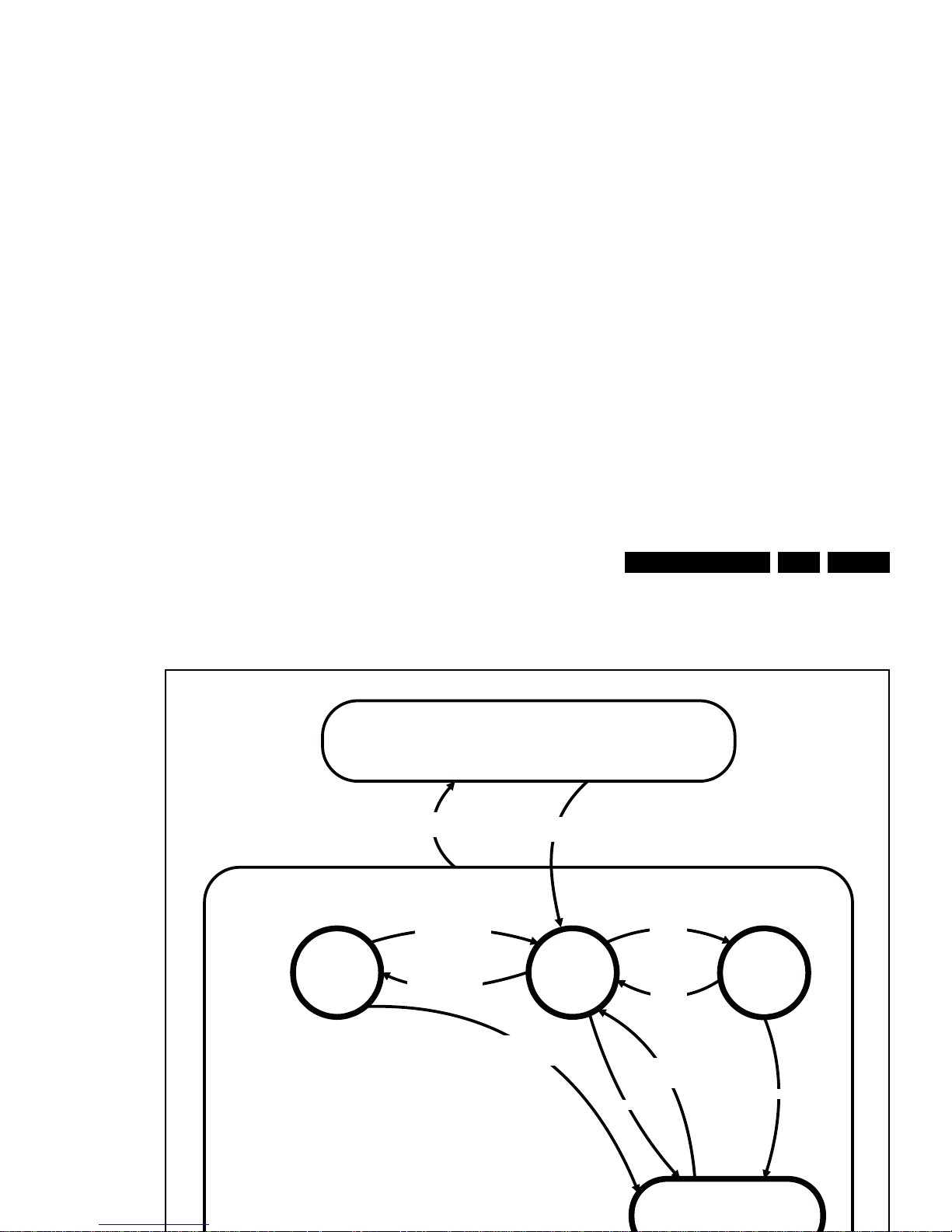
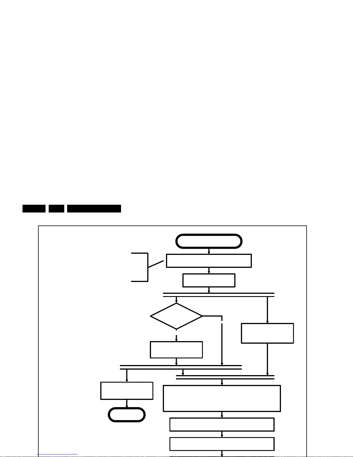
5.3 Start-up
As described, the start-up diagrams below, documents which
supplies are present at any certain moment.
Active
Off
Semi
St by
St by
Mains
on
Mains
off
GoToProtection
-WakeUp requested
-Acquisition needed
- stby requested and
no data Acquisition
required
St by
requested
WakeUp
requested
Protection
WakeUp
requested
(SDM)
GoToProtection
GoToProtection
(triggered during startup
by standby µP)
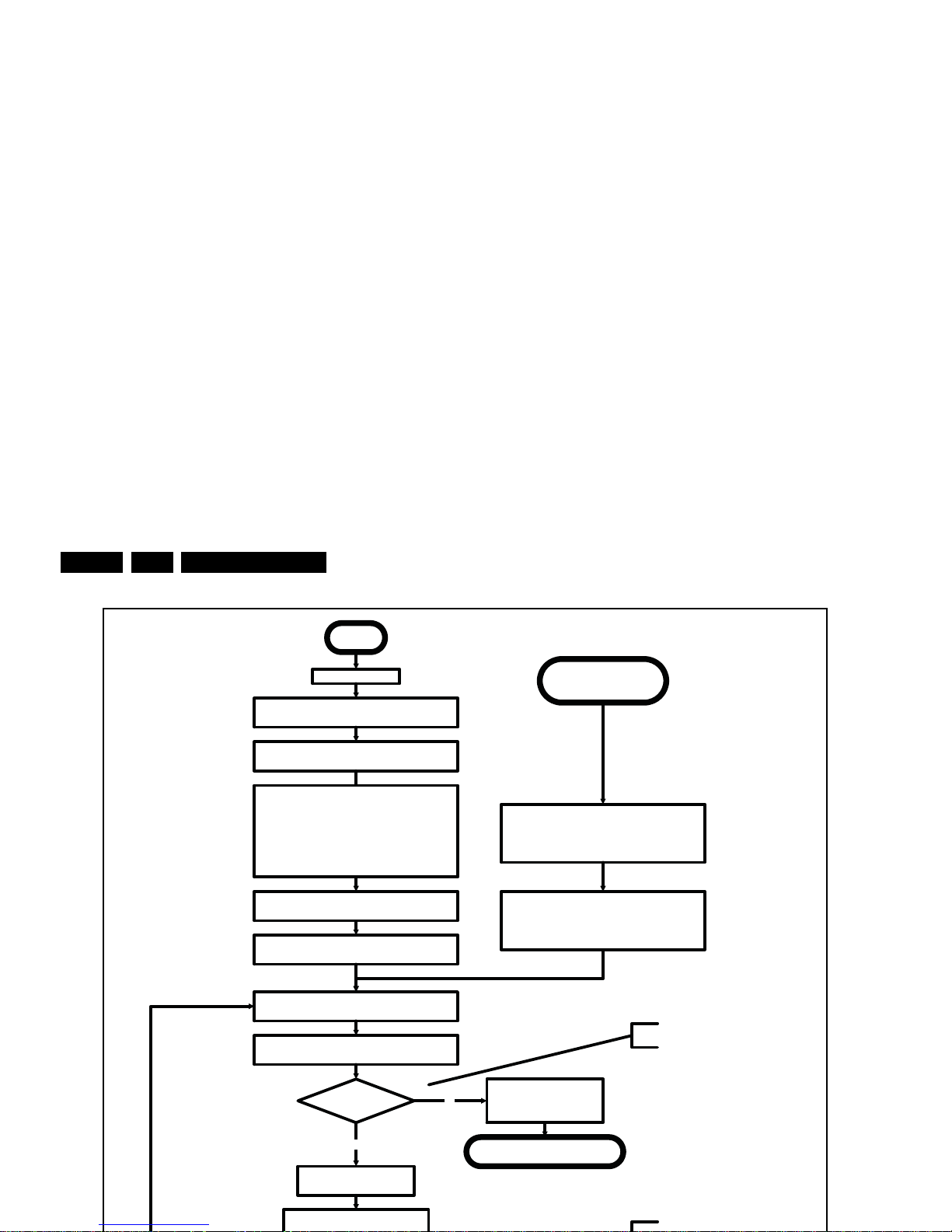
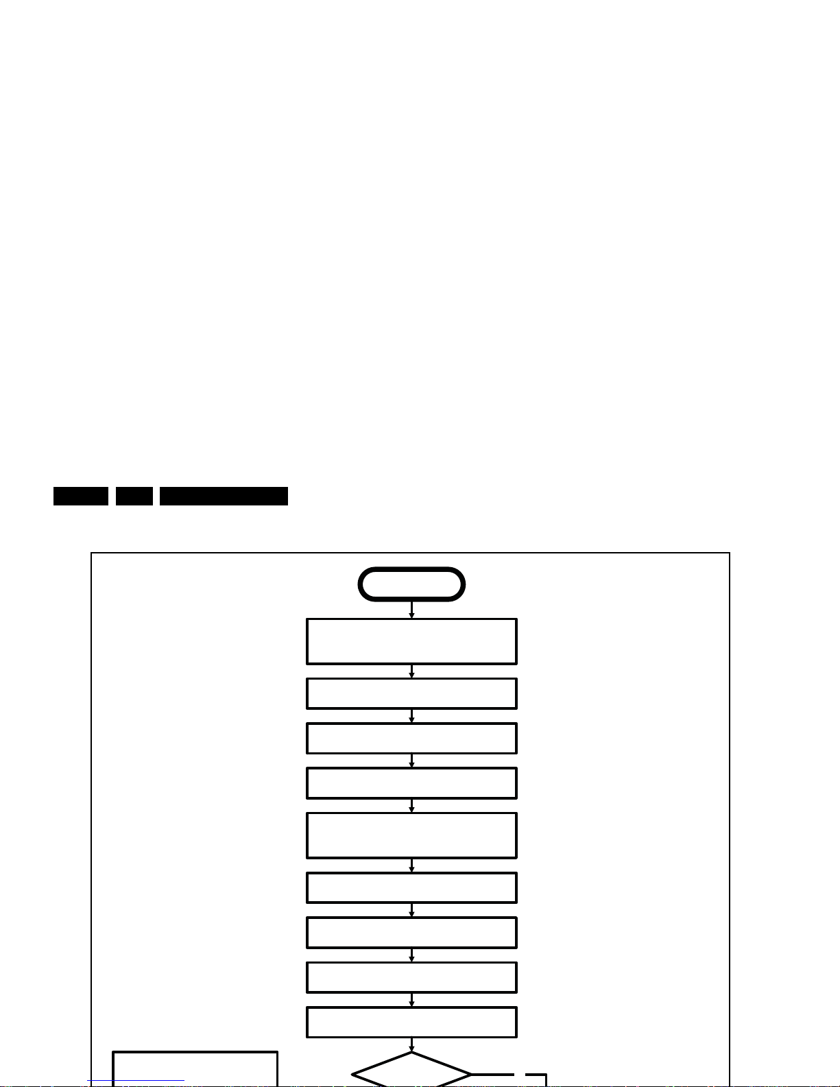
Service Modes, Error Codes, and Fault Finding
EN 24 QFU1.2E LA5.
Off
Standby Supply starts running.
All standby supply voltages become available.
st-by µP resets, resulting in a high impedant output
stage of the I/O ports.
Stand by or
Protection
AC~ Mains is applied
start keyboard scanning, RC detection.
Wake up reasons are off.
If the protection state was left by short circuiting the
SDM pins, detection of a protection condition during
startup shall stall the startup. Protection conditions
occuring in a playing set shall be ignored. The
protection mode shall not be entered.
12V platform is turned on, automatically enabling the
low voltage DCDC converter outputs
Enable the supply detect io n algorithm
Switch ON Platform supply by switching High the
STANDBYn line.
Initialise I/O pins of th e st-by µP
- Keep AVC syste m in reset (internal signal)
- Switch RESET-FUSION-OUTn LOW
- Switch RESET-HDMI-MUXn LOW
- Switch RESET-ETHERNETn LOW
- Switch AUDIO-MUTEn LOW
- Switch SPLASH-ON LOW
- Switch LCD-PWR-ONn High
No
Detect2 high received
within 2 seconds?
12V error:
Layer1: 3
Layer2: 16
Enter protection
Yes
Wait 300ms
All display related I/O lines should be
Switch ENABLE-WOLAN high to power Ethernet PHY
and Wifi dongle
Switch ENABLE-WOLANn high to power Ethernet
PHY and internal Wifi dongle if Networked Standby
was Off in the Standby mode.
Startup shall continue from the
moment a valid detection is received.
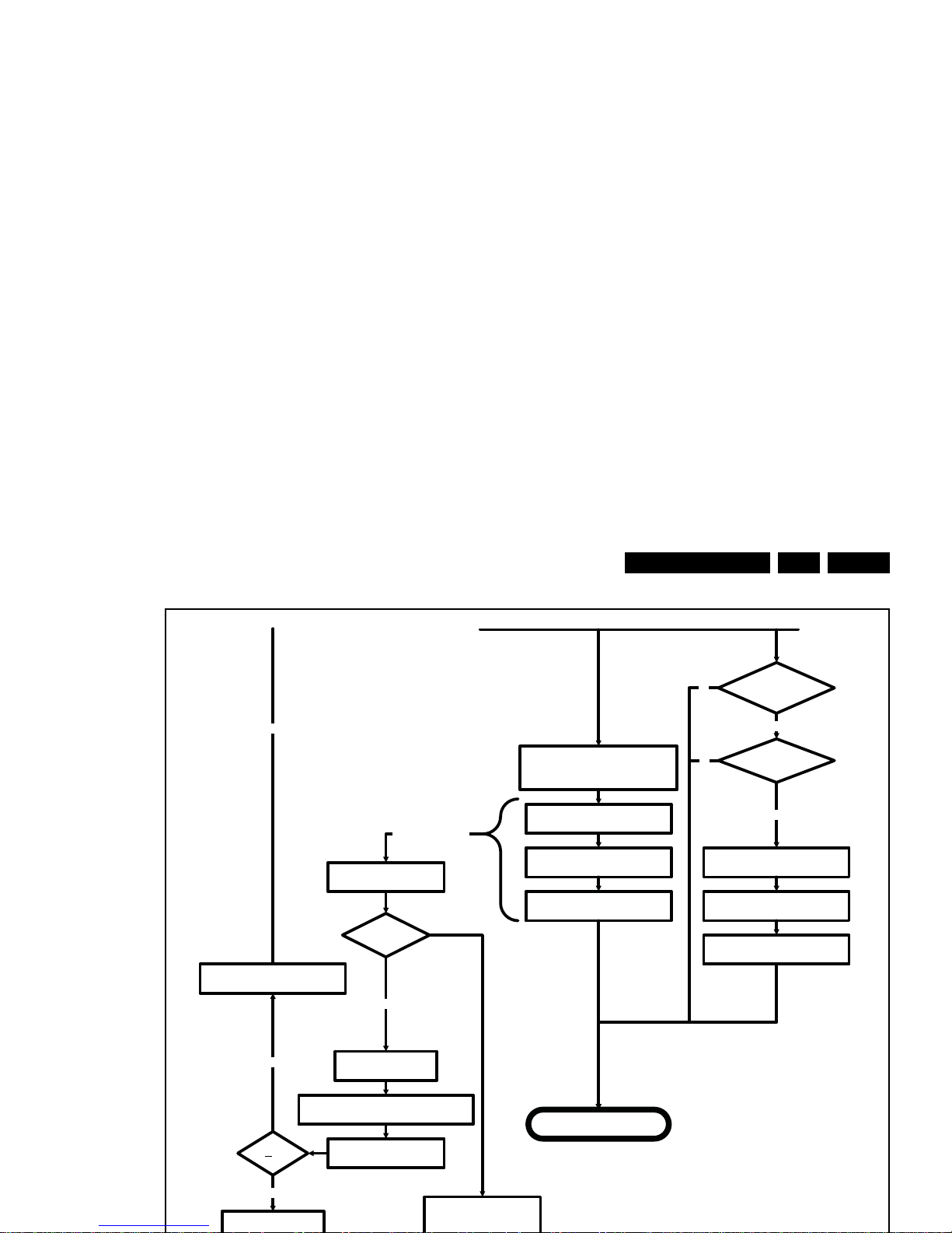
Service Modes, Error Codes, and Fault Finding
EN 25QFU1.2E LA 5.
Yes
Semi-Standby
3-th try?NoSwitch Standby I/ O l ine LOW
Switch AVC in reset
Wake up reason
coldboot to Active mode?
Startup screen cfg file
present?
yes
No
No
yes
AUDIO-MUTEn is switched by MIPS code
later on in the startup process w hen audio
needs to be released
Switch RESET-FUSION-OUTn, RESET-
HDMI-MUXn , RESET-ETHE RNETn Low
Boot is failing
Reset-lines are switched
MIPS boots
Standby µP monitors
boot process and will
init a restart if Boot
process hampers
TV application starts
Set was
started with
SDM pin?
Yes
Ignore boot failure:
Stall the startup process.
Blink Layer2 error 53.
No
Wait 4 seconds before restarting
No
Blink error code
MIPS sends out startup screen
MIPS starts up the display.
Startup screen visible
Service Modes, Error Codes, and Fault Finding
EN 26 QFU1.2E LA5.
Semi Standby
Initialize audio and video
processing IC's and functions
according needed use case.
Assert RGB video blanking
and audio mute
Wait until previous on-state is left more than2
secondsago. (to prevent LCD display problems)
The assumption here is that a fast toggle (<2s) can
only happen during ON->SEMI ->ON. In these states,
the AVC is still active and can provide the 2s delay. A
transition ON->SEMI->STB Y->SEMI->ON cannot be
made in less than 2s, because the standby state will
be maintained for at least 4s.
unblank the video
Wait until valid and stable audio and video, corresponding to the
requested output is delivered
AND
the backlight has been switched on for at least the time which is
indicated in the display file as preheat time
Release audio mute
No
Start POWER-OK line
detection algorithm as defined
in the CHS service.
return
Display already on?
(cold boot with splash
screen)
Yes
Startup display
(see separate tab)
Service Modes, Error Codes, and Fault Finding
EN 27QFU1.2E LA 5.
Semi Standby
Active
Mute all sound outputsaccording
information in the FMS AUDIO
Mute all video outputs switch off Ambilight (see CHS ambilight)
Wait 100ms
Wait until Ambilight has faded out:
Output power Observer should be zero
Switch off POK line detection
algorithm (see CHS service)
Shut down the display
(see separate sheet)
Switch Off LCD backlight
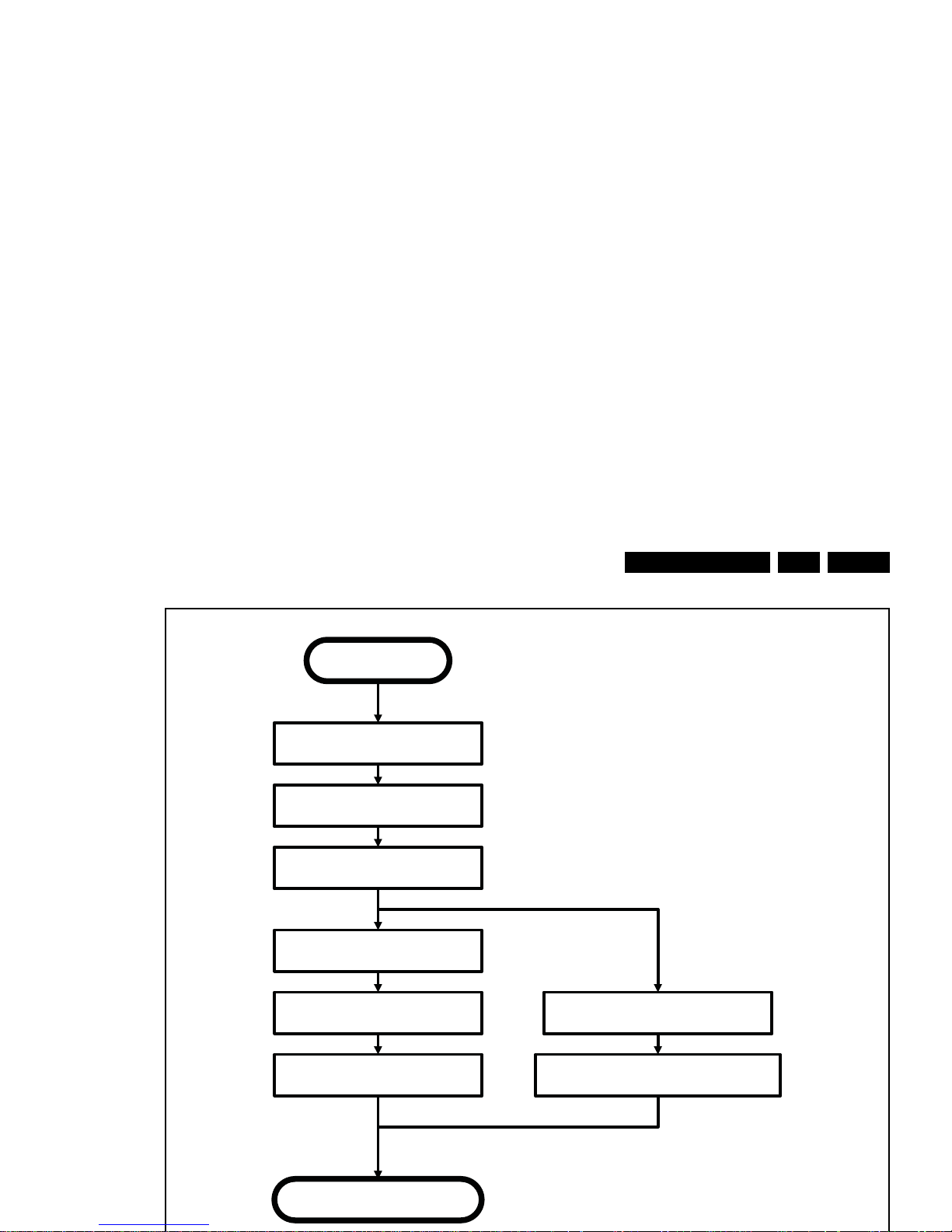
Service Modes, Error Codes, and Fault Finding
EN 28 QFU1.2E LA5.
transfer Wake up reasons to the Stand by µP.
Semi Stand by
Disable all supply related protections and switch off
the DC/DC converters (ENABLE-3V3n)
No
Switch OFF all supplies by switching HIGH the
Standby I/O line
Switch AVC system in reset state
Switch reset-USB, Reset-Ethernet and Reset-DVBs
LOW
Important remarks:
release reset audio 10 sec after entering
Wait 10ms
Delay transition until ramping down of ambient light is
finished. *)
If ambientlight functionality was used in semi-standby
(lampadaire mode), switch off ambient light (see CHS
ambilight)
*) If this is not performed and the set is
switched to standby when the switch off of
the ambilights is still ongoing, the lights will
switch off abruptly when the supply is cut.
Switch RESET-FUSION-OUTn, RESET-HDMI-MUXn ,
RESET-ETHERNETn Low
Networked Standby
required?
transfer specific Firmware and Wake up reasons to the
Wifi dongle to allow networked standby

Service Modes, Error Codes, and Fault Finding
EN 29QFU1.2E LA 5.
5.4 Service Tools
5.4.1 ComPair
The ComPair Tool is no longer supported.
5.5 Error Codes
5.5.1 Introduction
The error code buffer contains all detected errors since the last
time the buffer was erased. The buffer is written from left to
right, new errors are logged at the left side, and all other errors
shift one position to the right.
When an error occurs, it is added to the list of errors, provided
the list is not full. When an error occurs and the error buffer is
full, then the new error is not added, and the error buffer stays
intact (history is maintained).
To prevent that an occasional error stays in the list forever, the
error is removed from the list after more than 50 hrs. of
operation.
When multiple errors occur (errors occurred within a short time
span), there is a high probability that there is some relation
between them.
• If no errors are there, the LED should not blink at all in
CSM or SDM. No spacer must be displayed as well.
• There is a simple blinking LED procedure for board
level repair (home repair) so called LAYER 1 errors
next to the existing errors which are LAYER 2 errors (see
Table 5-2
).
– LAYER 1 errors are one digit errors.
– LAYER 2 errors are 2 digit errors.
• In protection mode.
– From consumer mode: LAYER 1.
– From SDM mode: LAYER 2.
• Fatal errors, if I2C bus is blocked and the set reboots,
CSM and SAM are not selectable.
– From consumer mode: LAYER 1.
– From SDM mode: LAYER 2.
• In CSM mode.
– When entering CSM: error(s) LAYER 1 will be
displayed via blinking LED.(attention: any new remote
• On screen via the SAM (only when a picture is visible).
E.g.:
– 00 00 00 00 00: No errors detected
– 23 00 00 00 00: Error code 23 is the last and only
detected error.
– 37 23 00 00 00: Error code 23 was first detected and
error code 37 is the last detected error.
– Note that no protection errors can be logged in the
error buffer.
• Via the blinking LED procedure. See section 5.5.3
How to
Clear the Error Buffer.
•Via ComPair.
5.5.3 How to Clear the Error Buffer
Use one of the following methods:
• By activation of the “RESET ERROR BUFFER” command
in the SAM menu.
• If the content of the error buffer has not changed for 50+
hours, it resets automatically.
5.5.4 Error Buffer
In case of non-intermittent faults, clear the error buffer before
starting to repair (before clearing the buffer, write down the
content, as this history can give significant information). This to
ensure that old error codes are no longer present.
If possible, check the entire contents of the error buffer. In
some situations, an error code is only the result of another error
code and not the actual cause.(e.g. a fault in the protection
detection circuitry can also lead to a protection)
There are several mechanisms of error detection:
• Via error bits in the status registers of ICs.
• Via polling on I/O pins going to the standby processor.
• Via sensing of analog values on the standby processor or
the Mips.
• Via a “not acknowledge” of an I
2
C communication.
Take notice that some errors need several minutes before they
start blinking or before they will be logged. So in case of
problems wait 2 minutes from start-up onwards, and then
check if the front LED is blinking or if an error is logged.
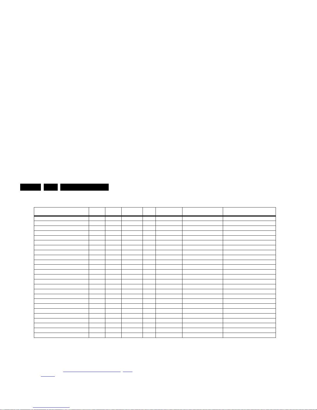
Service Modes, Error Codes, and Fault Finding
EN 30 QFU1.2E LA5.
Table 5-2 Error code overview
Extra Info
• Rebooting. When a TV is constantly rebooting due to
internal problems, most of the time no errors will be logged
or blinked. This rebooting can be recognized via a ComPair
interface and Hyperterminal (for Hyperterminal settings,
see section “5.8
Fault Finding and Repair Tips, 5.8.6
Logging). It’s shown that the loggings which are generated
by the main software keep continuing.
• Error 13 (I
2
C bus M3, SSB + SRF bus blocked). Current
situation: when this error occurs, the TV can reboot due to
the blocked bus. The best way for further diagnosis here, is
to check the logging output.
• Error 14 (I
2
C bus M2, BE bus blocked). Current situation:
LAYER 2 error = 28 will be logged and displayed via the
blinking LED procedure if SDM is switched on.
• Error 31 (Lnb controller). When there is no I
2
C
communication towards this device, LAYER 2 error = 31
will be logged and displayed via the blinking LED
procedure if SDM is activated.
• Error 34 (Tuner). When there is no I
2
C communication
towards the tuner during start-up, LAYER 2 error = 34 will
be logged and displayed via the blinking LED procedure
when SDM is switched on.
• Error 35 (main NVM). When there is no I
2
C
communication towards the main NVM during start-up,
LAYER 2 error = 35 will be displayed via the blinking LED
Description Layer 1 Layer 2
Monitored
by
Error/
Prot
Error Buffer/
Blinking LED Device Defective Board
I
2
CM3 (SSB + SRF bus) 2 13 MIPS E BL / EB SSB SSB
I2CM2 (BE bus) 2 14 MIPS E BL / EB SSB SSB
I
2
CM1(FE bus) 2 18 MIPS E BL / EB SSB SSB
PNX (Fusion) doesn’t boot 2 15 Stby µP P BL Fusion SSB
12V 3 16 Stby µP P BL / Supply
HDMI mux 2 23 MIPS E EB SII9287 SSB
I2C switch 2 24 MIPS E EB PCA9540 SSB
Channel dec DVB-T2 2 27 MIPS E EB CXD2834 SSB
Channel dec DVB-S2 2 28 MIPS E EB SI2169 SSB
Lnb controller 2 31 MIPS E EB LNBH25 SSB
Hybrid Tuner 2 34 MIPS E EB SUT-RE214Z SSB
Main NVM 2 35 MIPS E EB M24C64 SSB
Tuner DVB-S2 2 36 MIPS E EB STV611X SSB
Class-D 2 37 MIPS E EB TAS 5731 PHP SSB
µProcessor PQ 2 38 MIPS E EB LPC1114 SSB
IO Expander 2 41 MIPS E EB PCA9554 SSB
T° sensor SSB/set 2 42 MIPS E EB LM75 T° sensor/SSB
Light sensor 6 43 MIPS E EB TSL2571 Set
µP touch control 6 44 MI PS E EB / Set
RF4CE 6 46 MIPS E EB / Set
MIPS doesn’t boot (SW cause) 2 53 Stby µP P BL FUSION SSB
NT72314 9 61 MIPS E EB NT72314/ QFHD
NT68361 9 62 MIPS E EB NT68361/ QFHD
NT72314 not alive 9 63 MIPS E EB NT72314/ QFHD
NT68361 not alive 9 64 MIPS E EB NT68361/ QFHD
 Loading...