

Page 1
Colour Television Chassis
43PUT5801/56
49PUT5801/56
55PUT5801/56
Contents
Product Specification Sheet (Page1-10)
User Manuel Part(Page11-18)
Troubleshooting Procedure(Page19-24)
Factory Mode Adjustment (Page25-26)
Software Upgrades(After Service)(Page27-36)
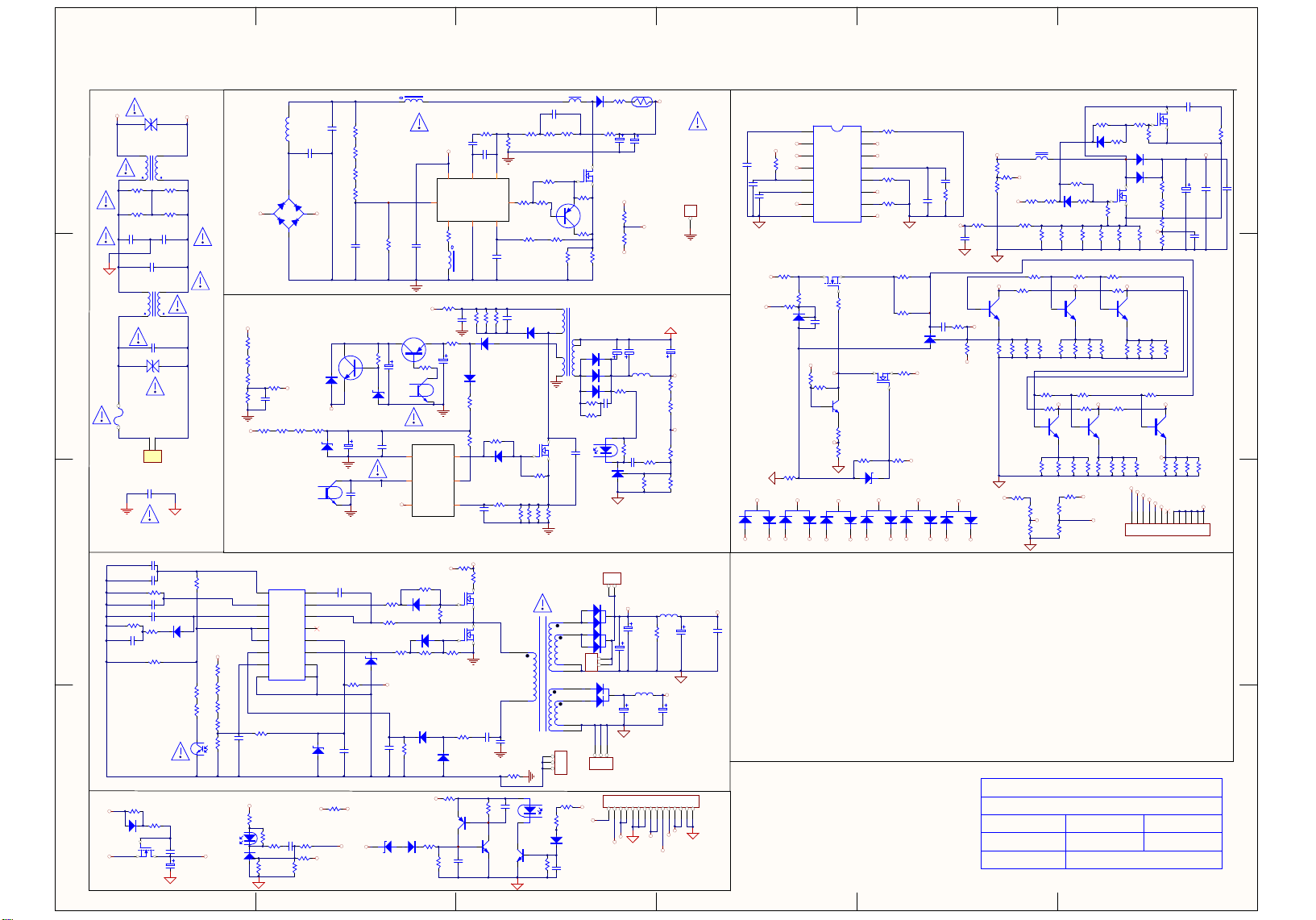
Power Board Circuit Diagram (Page37)
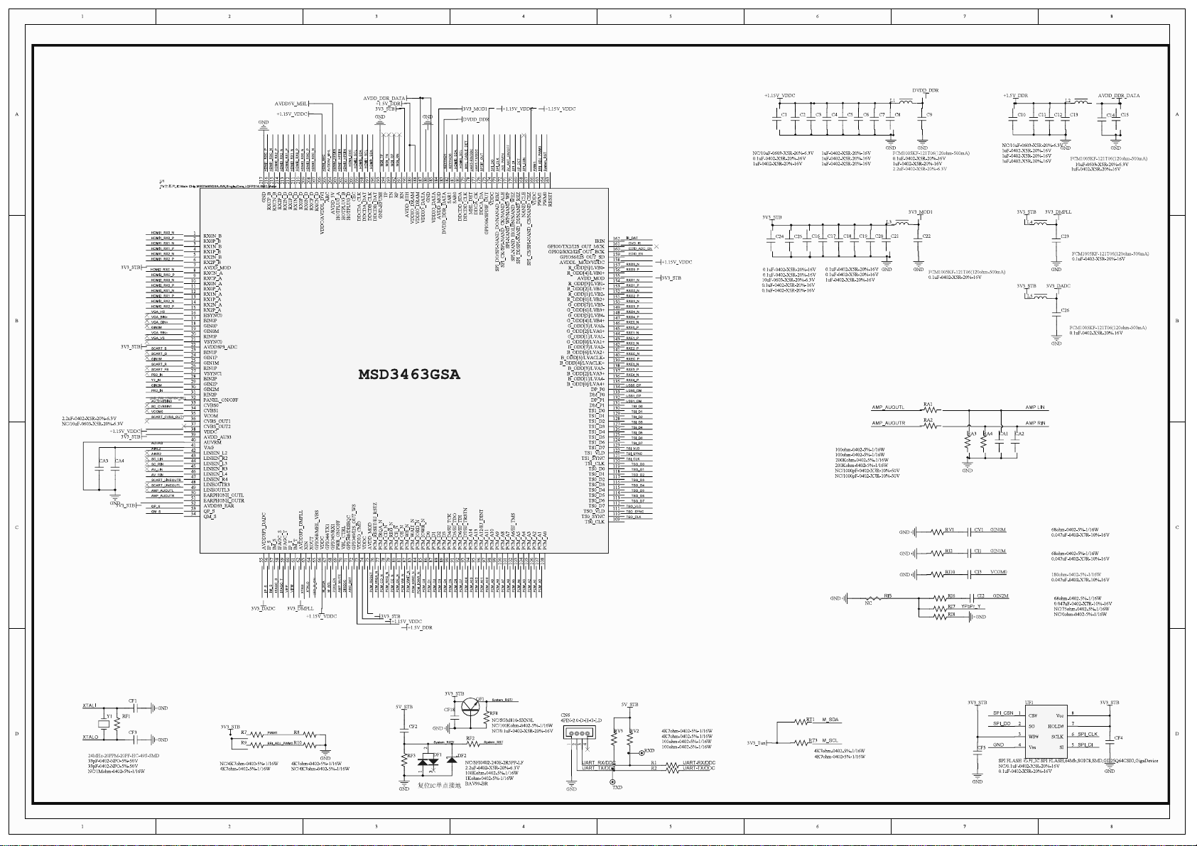
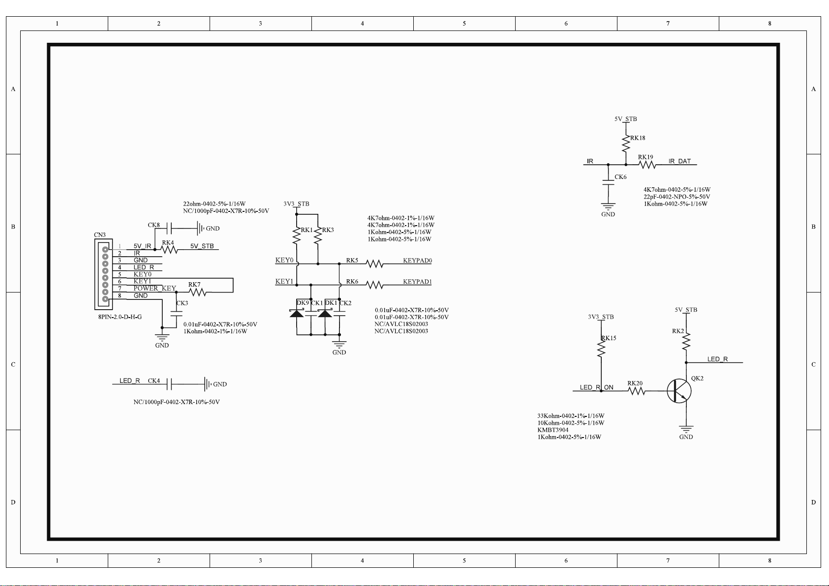
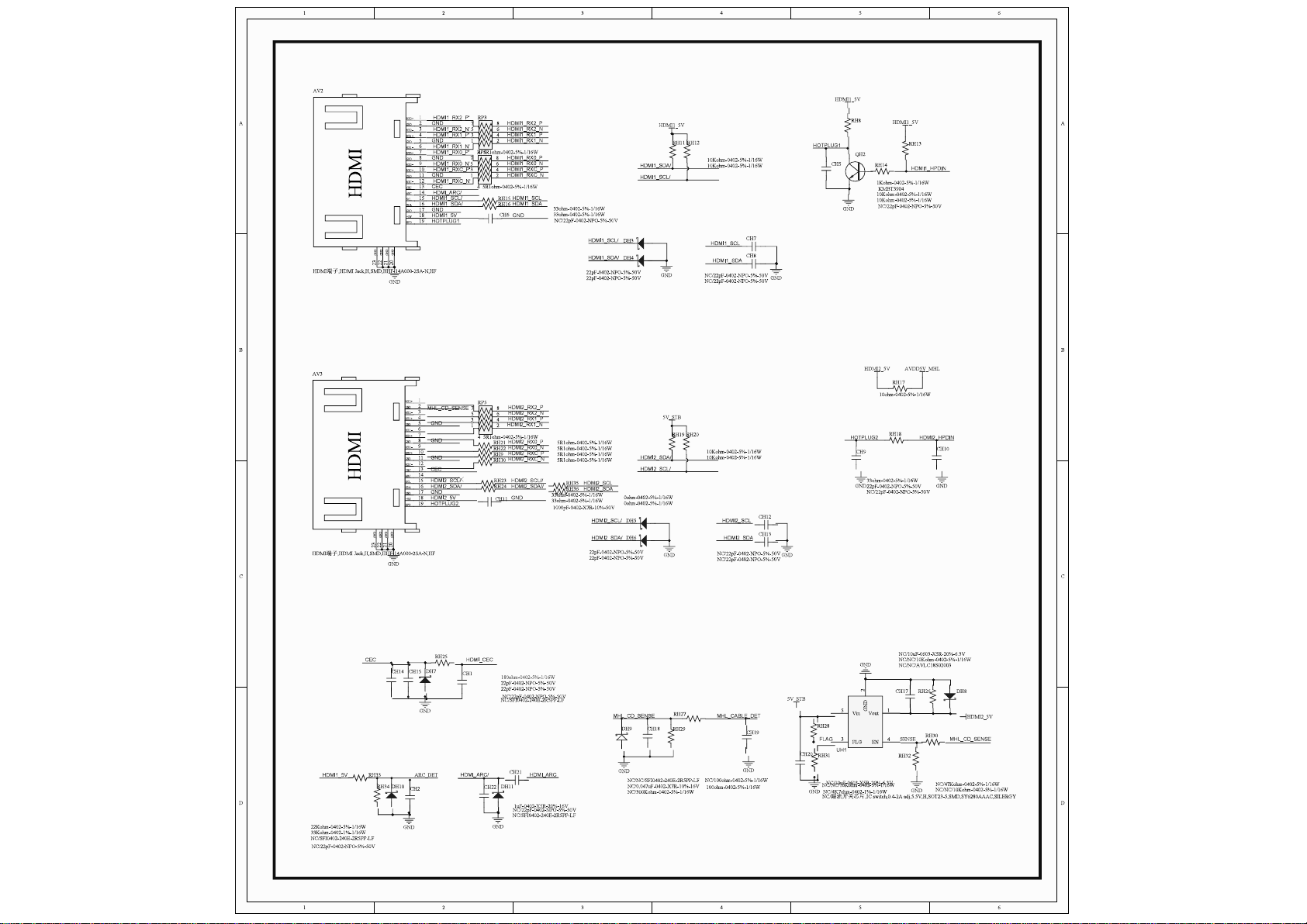
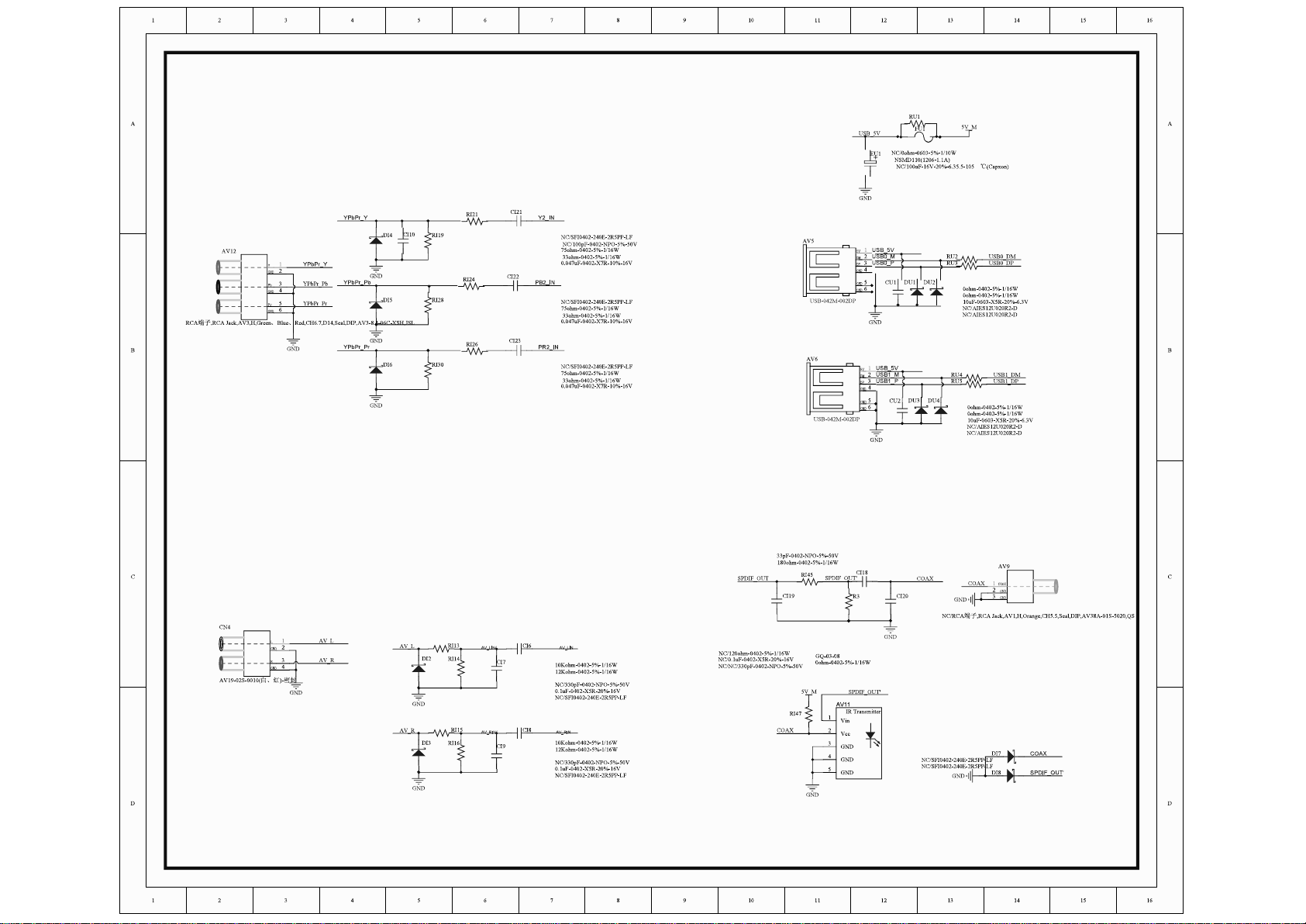
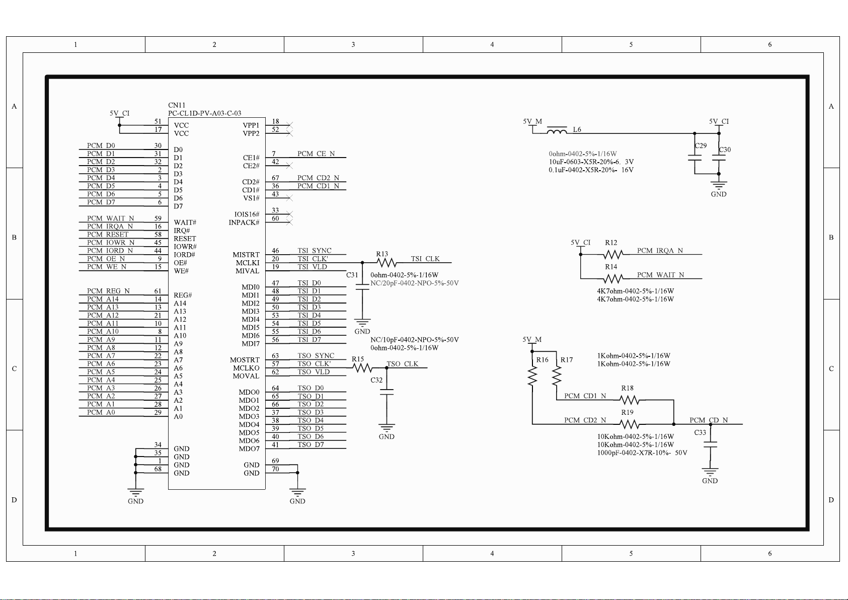
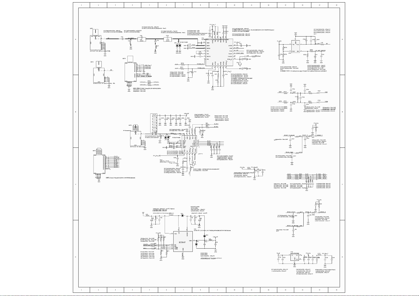
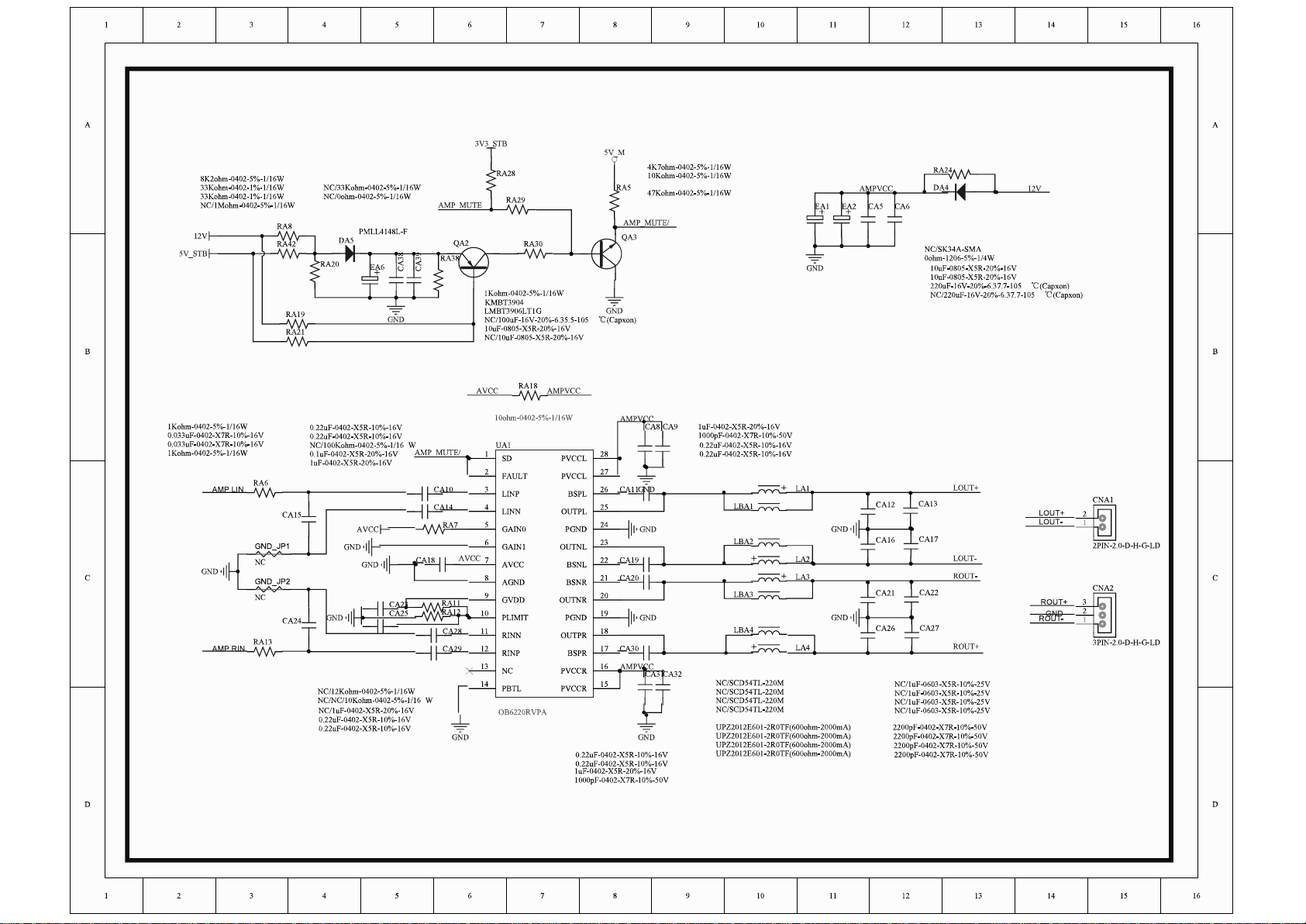
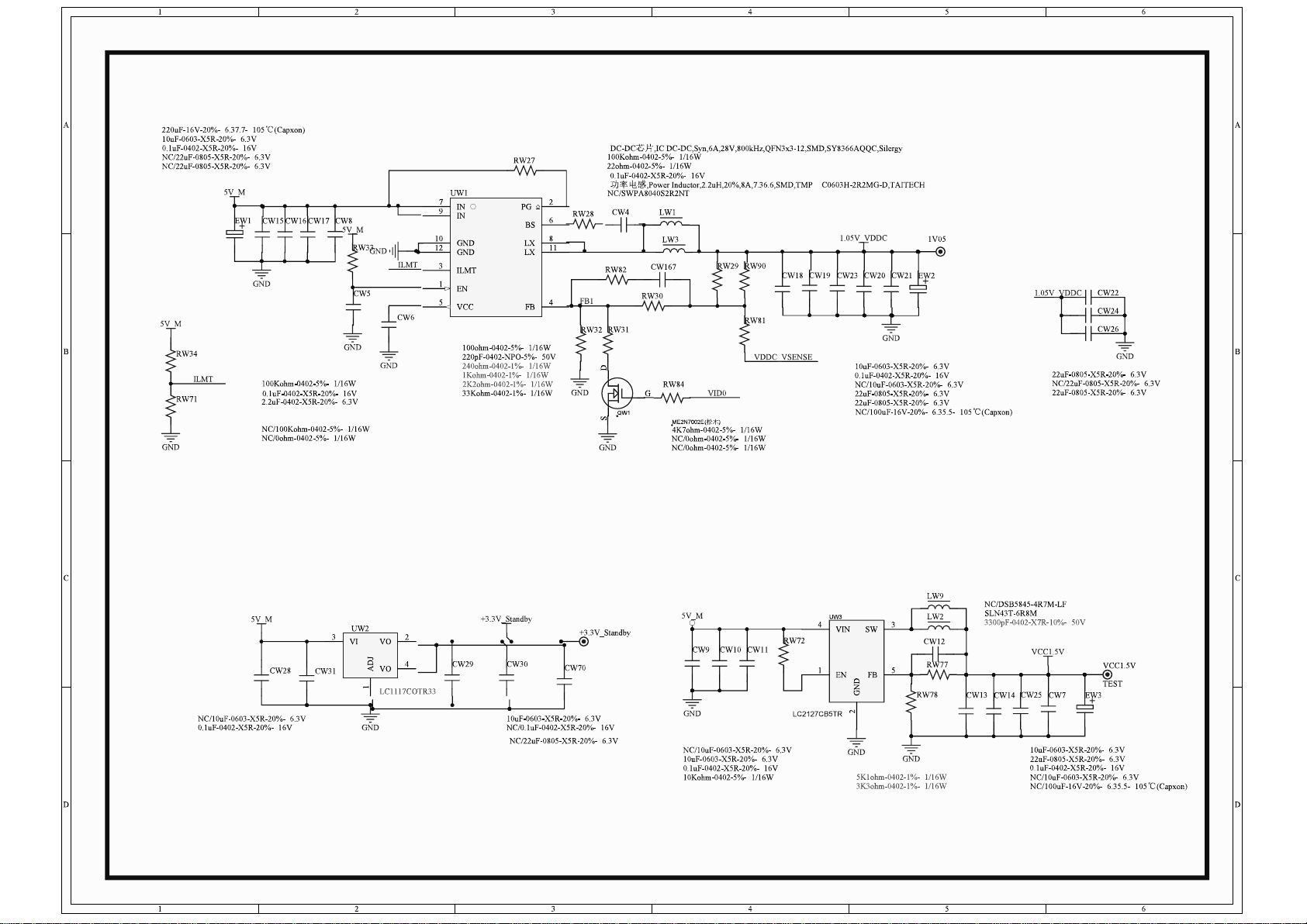
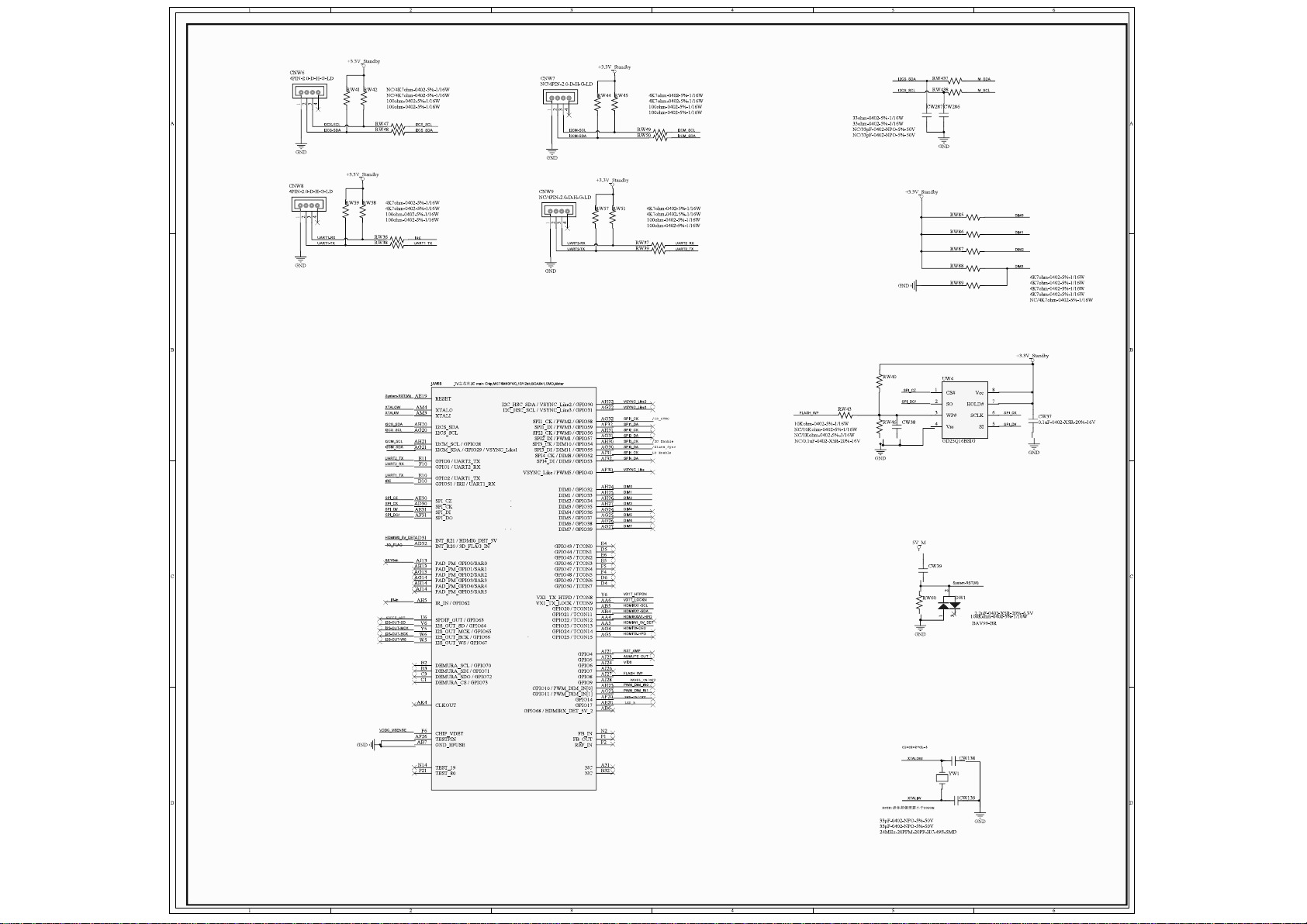
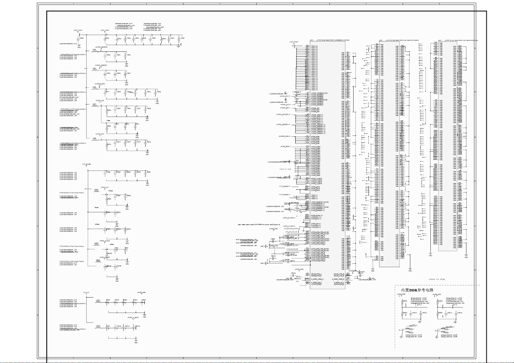
Main Board Circuit Diagram (Page38-51)
Page
Page 2
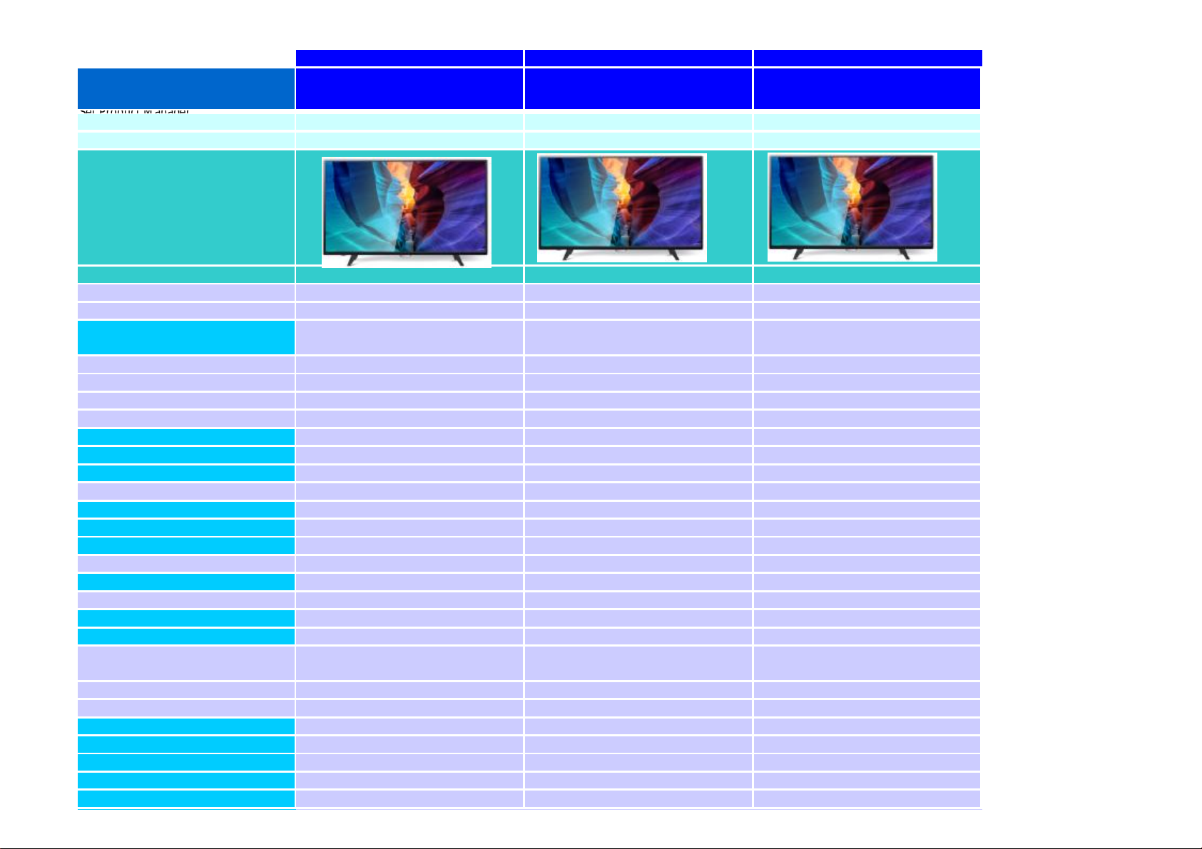
Product Specification Sheet
43" UHD DTV(43L91U-DVB) 49" UHD DTV(49L91U-DVB) 55" UHD DTV(55L91U-DVB)
Series name 43PUT5801 49PUT5801 55PUT5801
Platform/Chipset T.MS3463S.U701 DVB-T2 T.MS3463S.U701 DVB-T2 T.MS3463S.U701 DVB-T2
Processor type (CPU) / GPU
Picture/Display
RC 7601-32E232-0244FLP1 7601-32E232-0244FLP1 7601-32E232-0244FLP1
Backlight Type (Panel Supplier) DLED DLED DLED
Diagonal Screen Size 42.51” 48.5" 54.64"
Perfect Motion Rate
Picture Performance Index
Panel Frequency (Native) 60HZ 60HZ 60HZ
Chasis Frequency 60HZ 60HZ 60HZ
Backlight Dimming PWM PWM PWM
Scanning Segments (amount) 48.25--863.25MHZ 48.25--863.25MHZ 48.25--863.25MHZ
Panel Resolution 3840*2160 3840*2160 3840*2160
Aspect ratio 16:09 16:09 16:09
Brightness (Home Vivid Mode) cd/m²
Panel contrast ratio 1200:1 1200:1 1200:1
Viewing Angle - H (L+R)
Viewing Angle - V
Response Time (ms)
Analog + PWM dimming YES YES YES
2D/3D Logic (2D/3D Active/3D Passive)
Color Gamut NTSC 65% NTSC 65% NTSC 66%
PQ engine Digital Crystal Clear Digital Crystal Clear Digital Crystal Clear
PQ Resolution N/A N/A N/A
Directional Super Resolution (on 2D &
3D)
Improved 3D Super Resolution N/A N/A N/A
ISF Color Management N/A N/A N/A
Digital Natural Motion (2D/3D)
Perfect Natural Motion (2D/3D)
2D to 3D Conversion N/A N/A N/A
3D Depth adjustment (Auto/Offset) N/A N/A N/A
Auto 3D Detection N/A N/A N/A
Min:220cd/m2 ,Typ:260cd/m2(LCM) Min:280cd/m2;Typ:330cd/m2(LCM) Min:300cd/m2;Typ:350cd/m2(LCM)
2D 2D 2D
500 PPI 500 PPI 500 PPI
176° 176° 176°
176° 176° 176°
8ms 6ms 9ms
N/A N/A N/A
N/A N/A N/A
N/A N/A N/A
1
Page 3
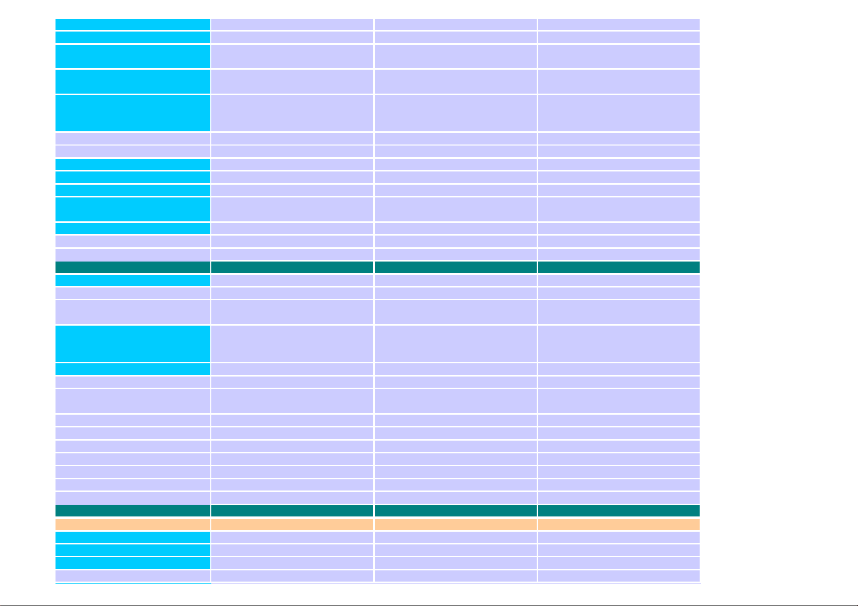
Micro Dimming Demo N/A N/A N/A
Micro Dimming mode N/A N/A N/A
Dual View (2 Player Full Screen
Gaming/Video) 双屏
Supported Display Resolution (Computer
Inputs)
Supported Display Resolution (Video
Inputs)
Brightness (Shop Vivid mode: 10% boost)
Pixel Plus Link (I/II/III)
Active Control
Local Contrast
"UHD Display" - logo (Industry)
"UHD Receiver" - logo (Industry) -
pending std
HDMI 2.0 4:4:4 @ 60p
10-bit color support
DAPQ
Ambilight
Ambilight Version N/A N/A N/A
Pixels N/A N/A N/A
Ambilight Performance (nit, no of colors,
halo length)
Ambilight Features (Wall colour
adaptive, Lounge Light Mode, Ambilight
Motion, Gaming Mode)
Ambilight for 3D N/A N/A N/A
Ambilight for all TV Events N/A N/A N/A
Ambilight Open Source via
JointSpaceApp
Wall Distance Adaptive (Stand vs Mount) N/A N/A N/A
Motion Adaptive N/A N/A N/A
Built-in AL + Hue N/A N/A N/A
TV as Lamp(s) in Hue ecosystem N/A N/A N/A
In screen demo in mobile shop app N/A N/A N/A
Ambi Wakeup (ref HTV) N/A N/A N/A
Ambimusic N/A N/A N/A
Sound (TV)
Sound (Internal)
Output Power (10% THD) RMS 16W 16W 16W
Speaker configuration 8W+8W 8W+8W 8W+8W
Speaker system 2.0 2.0 2.0
Speaker type built-in(normal) built-in(normal) built-in(normal)
576p,720p,1080i,1080p,2160p(24/25/30/5
N/A N/A N/A
N/A N/A N/A
480i, 480p,576i,
576p,720p,1080i,1080p,2160p(24/25/30/5
0/60Hz)
YES(1% boost) YES(1% boost) YES(1% boost)
N/A N/A N/A
N/A N/A N/A
N/A N/A N/A
N/A N/A N/A
N/A N/A N/A
N/A N/A N/A
N/A N/A N/A
N/A N/A N/A
N/A N/A N/A
N/A N/A N/A
N/A N/A N/A
480i, 480p,576i,
0/60Hz)
480i, 480p,576i,
576p,720p,1080i,1080p,2160p(24/25/30/5
0/60Hz)
2
Page 4
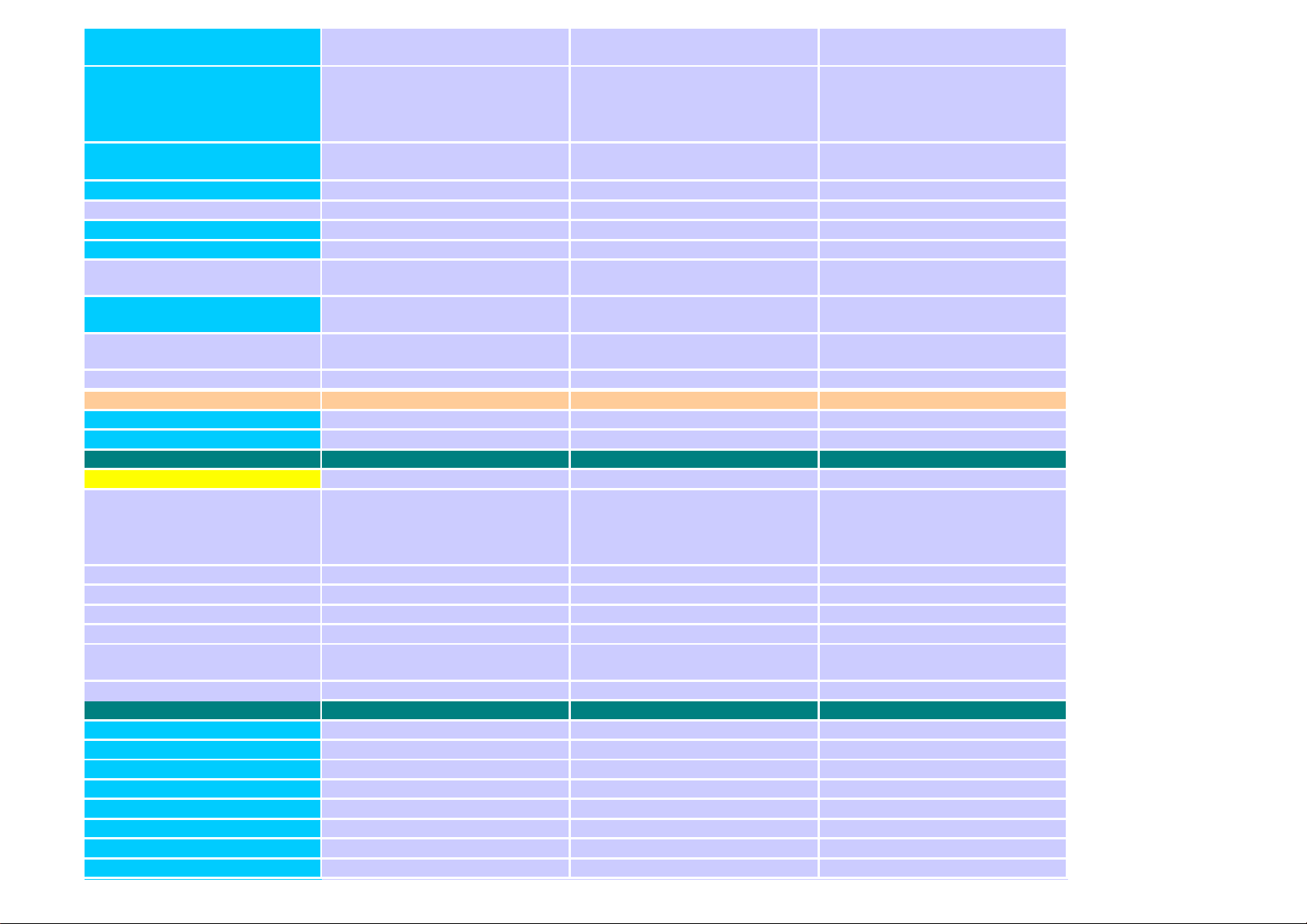
Auto Volume Levelier / Auto Volume
Levelier +
Sound Claim (Incredible
Surround/Cinema Surround/Clear
Sound/AmbiwOOx/3D Movie/Incredible
Surround 3D)
Bass (Bass control/DBE/Ultra Bass/Ultra
Bass II)
Wireless Sound Interface N/A N/A N/A
Dolby Digital DecoderType
DTS Studio Sound
DTS 2.0+ Digital out
Acoustic Compensation Filters 主板滤
波补偿
Dynamic Treble Enhancement 动态
高音增强
Programmable Bass And Treble Curve
(可编程的低音和高音曲线)用户
Visible Sound
Sound (External)
External Sound device type N/A N/A N/A
Output Power (10% THD) RMS N/A N/A N/A
Design Specs
Stand type (Swivel/non Swivel) Metal Wing Metal Wing Metal Wing
I/O port to be clearly indicated (列接
口)
Local Keyboard 按键板 YES YES YES
Philips wordmark 商标logo PHILIPS PHILIPS PHILIPS
Leading Edge 装饰件 #7 #7 #7
Vesa Wall Mount Compatible 壁挂孔 YES YES YES
Compatible Wall Mount 壁挂孔规
格
POS label
Connectivity (I/O)
HDMI Number *4 *4 *4
HDMI 1.4a HDMI-3&HDMI-4(Side-out) HDMI-3&HDMI-4(Side-out) HDMI-3&HDMI-4(Side-out)
HDMI 2.0 HDMI-1(Side-out)&HDMI-2(Under-out) HDMI-1(Side-out)&HDMI-2(Under-out) HDMI-1(Side-out)&HDMI-2(Under-out)
HDMI/DVI YES YES YES
HDMI ARC HDMI-3 HDMI-3 HDMI-3
EasyLink (HDMI-CEC) YES YES YES
Scart (EU) Connections N/A N/A N/A
YPbPr/CVI (EU/Latam) Connections *1 *1 *1
/HDMI*4/YPBPR*1/CVBS*1/Audio L+R
YES YES YES
N/A N/A N/A
N/A N/A N/A
YES YES YES
N/A N/A N/A
N/A N/A N/A
N/A N/A N/A
N/A N/A N/A
N/A N/A N/A
N/A N/A N/A
TV*1/USB*2
/HDMI*4/YPBPR*1/CVBS*1/Audio L+R
in*1/
Optical-OUT*1
200mm×300mm 200mm×300mm 200mm×300mm
TV*1/USB*2
in*1/
Optical-OUT*1
TV*1/USB*2
/HDMI*4/YPBPR*1/CVBS*1/Audio L+R
in*1/
Optical-OUT*1
3
Page 5
CVBS (EU/Latam) Connections *1 *1 *1
Audio L/R in *1 *1 *1
CI+ slots NO NO NO
Antenna *1 *1 *1
Satellite (for K&S only) N/A N/A N/A
USB USB2.0*2 USB2.0*2 USB2.0*2
USB Harddisk Format (Power) FAT FAT FAT
VGA NO NO NO
VGA/DVI Audio Input share Audio L/R in share Audio L/R in share Audio L/R in
Digital audio out (SPDIF) *1 Optical *1 Optical *1 Optical
Headphone NONE NONE NONE
Ethernet-LAN RJ-45 N/A N/A N/A
Service Connector NONE NONE NONE
Wireless connections N/A N/A N/A
Wi-Fi Band Concurrent N/A N/A N/A
WoWLAN N/A N/A N/A
WoLAN N/A N/A N/A
Bluetooth for subwoofer/RC (do not
claim commercially)
Multichannel over BT N/A N/A N/A
HDCP v2.2 (on HDMI 2.0 port) N/A N/A N/A
MHL (HDMI+power+return channel) HDMI-4 HDMI-4 HDMI-4
Wi-fi Miracast Certified (HDCP 2.2
supported)
GoogleCast Receiver N/A N/A N/A
Tablet Screen Mirroring (Wi-Fi Miracast) N/A N/A N/A
TAD AppFTA channels (free app) N/A N/A N/A
TAD Server, FTA channel N/A N/A N/A
Indep. Watching (TV&PVR), FTA&CI+ N/A N/A N/A
SAT>IP Client, FTA N/A N/A N/A
HEVC @ FHD 60Hz YES YES YES
HEVC @ UHD 60Hz N/A N/A N/A
H264 @ UHD N/A N/A N/A
VP9 @ UHD N/A N/A N/A
UI & Interaction
Ux (Basic: without Dashboard,
Advanced: with Dashboard)
Animations 动画 N/A N/A N/A
Drag and drop 拖动 N/A N/A N/A
Remote Control Version (state if include
Keyboard/Pointer)
Sensor.accelerometer & sensor
gyroscope
N/A N/A N/A
N/A N/A N/A
Basic Basic Basic
N/A N/A N/A
N/A N/A N/A
4
Page 6
Easy access to eDFU (Blue key) 电子说
明书
Text Entry (Basic : Text Entry via HID
and/or On-screen Keyboard)
Multi-view 多屏显示 N/A N/A N/A
Multi-task 多任务 N/A N/A N/A
Screen Format Adjustments 比例列表 4:3,16:9 4:3,16:9 4:3,16:9
Dual Screen (TV and TeleText) 图文 N/A N/A N/A
Teletext YES YES YES
e-Sticker N/A N/A N/A
Priority Channel List N/A N/A N/A
Channel Cloning via USB N/A N/A N/A
Logo Editor (Channel Editor) N/A N/A N/A
Channel Matrix with EPG data N/A N/A N/A
Channel Scanning (Australia/NZ) N/A N/A N/A
Time Zone (Australia/NZ) N/A N/A N/A
PC Sorting N/A N/A N/A
Intelligent Source List N/A N/A N/A
On-screen Remote (via HDMI) N/A N/A N/A
Cold boot to broadcast N/A N/A N/A
Cold boot to online dashboard N/A N/A N/A
Warm boot to broadcast N/A N/A N/A
Warm boot to online dashboard N/A N/A N/A
Zapping OSD with EPG data N/A N/A N/A
Electronic Program Guide (IP &
Broadcast)
8 Days Electronic Program Guide YES YES YES
Live Setting Assistant (include PQ level)
设置助手直播
Signal Strength Indication 信号强
度指示
Pause TV/USB recording (PVR) 刻录 YES YES YES
Two simultaneous recordings in stdby N/A N/A N/A
UI Languages
Memory Profile (DRAM) 8MB 256MB 256MB
Menu Layout Update 菜单更新
换UI
Wizards (Ease of Installation) 安装
工具(类似螺丝刀)
Single Sign On (google a/c only) N/A N/A N/A
Personalized Dashboard(定制化UI) N/A N/A N/A
Face recognition 面部识别 N/A N/A N/A
Shopmode 2015 N/A N/A N/A
English, Malaysia, Indonesian, Thai,
N/A N/A N/A
Basic Basic Basic
N/A N/A N/A
N/A N/A N/A
YES YES YES
English, Malaysia, Indonesian, Thai,
Vietnamese,Chinese
N/A N/A N/A
N/A N/A N/A
Vietnamese,Chinese
English, Malaysia, Indonesian, Thai,
Vietnamese,Chinese
5
Page 7
CloudTV app content in search and
ad
Dashboard (on TV)
Firmware Upgradeable 软件升级 YES YES YES
Multimedia Applications
Video Playback Formats MPEG-2/MPEG-4 /H.264/HEVC MPEG-2/MPEG-4 /H.264/HEVC MPEG-2/MPEG-4 /H.264/HEVC
Subtitles Formats Support SRT、ASS SRT、ASS SRT、ASS
Music Playback Formats
Picture Playback Formats JPEG、BMP、PNG JPEG、BMP、PNG JPEG、BMP、PNG
Smart TV N/A N/A N/A
Software Platform
Android Home Page
Android OS
UI Resolution
Google Voice Search
Google Hangouts
Remote Control
Gesture
Pre-installed Google Apps (Google
Search, Google Hangouts, Google Play
Movies, Google Play Music, Youtube)
Basic Performance Profile
Google Play
Memory size to install apps N/A N/A N/A
Extendable USB storage for App
Smart TV Experience
DLNA 1.5 - DMR, DMP
DLNA 1.5 - DMS
MultiRoom Client, FTA+Scrambled Non-
Copy Protected & CI+
MultiRoom Server, FTA+Scrambled Non-
Copy Protected & CI+
PVR Auto Recording (IP-EPG)
API - access control N/A N/A N/A
xTV Support
Rich User Interaction
Smart Home N/A N/A N/A
4k photo support in Android apps N/A N/A N/A
4k photo support in Picture apps N/A N/A N/A
4k photo support in USB/DLNA N/A N/A N/A
UHD content playback from all sources
(USB,DLNA,web)
NextFlix UHD
Youtube UHD
Downlo
MPEG-1,MPEG-2(Layer I/II),MP3,
N/A N/A N/A
MPEG-1,MPEG-2(Layer I/II),MP3,
AAC-LC, HE-AAC
N/A N/A N/A
N/A N/A N/A
N/A N/A N/A
N/A N/A N/A
N/A N/A N/A
N/A N/A N/A
N/A N/A N/A
N/A N/A N/A
N/A N/A N/A
N/A N/A N/A
N/A N/A N/A
N/A N/A N/A
N/A N/A N/A
N/A N/A N/A
N/A N/A N/A
N/A N/A N/A
N/A N/A N/A
N/A N/A N/A
N/A N/A N/A
N/A N/A N/A
N/A N/A N/A
N/A N/A N/A
N/A N/A N/A
AAC-LC, HE-AAC
MPEG-1,MPEG-2(Layer I/II),MP3,
AAC-LC, HE-AAC
Page 8
Google Play UHD N/A N/A N/A
Smart TV with Broadcast PIP; single
video
SMART TV offline content (cached) N/A N/A N/A
MPEG-DASH (CENC & CFF) N/A N/A N/A
HLS
Wake up from APP N/A N/A N/A
Preinstalled Apps
Netflix *
YouTube Leanback (HTML5) *
Spotify *
BBC iPlayer *
Skype
Skype Cowatch (mix audio)
Cloud Explorer
Cloud TV
Smart TV Services N/A N/A N/A
Social Apps N/A N/A N/A
Game Dashboard in Google launcher
OpenGL Games
Playstation Now App
OnLive App
STA 3.0 & 4.0 Clients
STA shared App store
Camera & Mic API
TV as an app (Verimatrix, etc)
Companion Apps
Philips TV Remote App N/A N/A N/A
Sharing in Remote App
Ambilight TV App
Ambilight+Hue App
User Manual App
Channel Editor - PC Client App
Mobile app for in-shop (cover
MRA/Demo Me/Shop RC functions)
Proximity based shop app activation
(BTLE/NFC/QR tbc)
MyRemote App (Old TV Remote App)
Ambilight Lounge App
N/A N/A N/A
N/A N/A N/A
N/A N/A N/A
N/A N/A N/A
N/A N/A N/A
N/A N/A N/A
N/A N/A N/A
N/A N/A N/A
N/A N/A N/A
N/A N/A N/A
N/A N/A N/A
N/A N/A N/A
N/A N/A N/A
N/A N/A N/A
N/A N/A N/A
N/A N/A N/A
N/A N/A N/A
N/A N/A N/A
N/A N/A N/A
N/A N/A N/A
N/A N/A N/A
N/A N/A N/A
N/A N/A N/A
N/A N/A N/A
N/A N/A N/A
N/A N/A N/A
N/A N/A N/A
N/A N/A N/A
N/A N/A N/A
Broadcast/Certification
DVB-T/C N/A N/A N/A
DVB-S/S2 N/A N/A N/A
DVB-T/T2 YES YES YES
7
Page 9
DVB-C2 N/A N/A N/A
SBTVD-T (Brazil) N/A N/A N/A
SATVD-T (Argentina) N/A N/A N/A
Analog (LATAM/APMEA) PAL SECAM NTSC PAL SECAM NTSC PAL SECAM NTSC
Nicam (APMEA) N/A N/A N/A
Enhanced SSU N/A N/A N/A
Italy HD Book 2.1.1 (GOLD) N/A N/A N/A
HD-Book Italy 3.0 (HEVC@FHD) N/A N/A N/A
UK D Book 7a N/A N/A N/A
Freeview SD (UK) N/A N/A N/A
Freeview HD (UK) N/A N/A N/A
MHEG 5(只有HbbTV有) N/A N/A N/A
TiVuON (IT) N/A N/A N/A
TNT HD (FR) N/A N/A N/A
Argentina Ginga - NCL N/A N/A N/A
Brazil Ginga (A/B) N/A N/A N/A
Video Playback N/A N/A N/A
Dual Cam (CI+) N/A N/A N/A
Dual Tuner N/A N/A N/A
CI+ 1.4 Multistream CAM N/A N/A N/A
CI+ 1.3 CAM N/A N/A N/A
HBBTV 1.5 N/A N/A N/A
HBBTV 2.0 N/A N/A N/A
MHP N/A N/A N/A
Ziggo Interactief N/A N/A N/A
3D DVB Phase 1 N/A N/A N/A
3D signaling bits in broadcast N/A N/A N/A
Background update installation N/A N/A N/A
Marlin/ Play ready N/A N/A N/A
Sustainability/Power
PVC / BFR Free 无卤 N/A N/A N/A
Mercury Free 无汞 N/A N/A N/A
Cabinet Resin 面框材质 SGCC ABS ABS
Eco-Flower Certified N/A N/A N/A
ECO Mode N/A N/A N/A
Mains Power AC 100-240V 50/60Hz AC 100-240V 50/60Hz AC 100-240V 50/60Hz
Standby Power <0.5W <0.5W <0.5W
Quick Startup N/A N/A N/A
Network Standby mode (max 6W) N/A N/A N/A
Off Mode Power <0.5W <0.5W <0.5W
Auto Switch-Off Timer 休眠时间 YES YES YES
Green packaging (Non-EPS) 绿色包
装
Light Sensor 光感应器 N/A N/A N/A
YES YES YES
8
Page 10
Picture Mute (For Radio) 单独听 N/A N/A N/A
EU Energy Label (A++/A+/A/B) -
Requirement
non-EU Energy Label - Standby Label
(A/B/C)
Blauer Engel (Germany) N/A N/A N/A
Accessory
By-packed accessories
Active Glasses (509) N/A N/A N/A
Active Glasses (529) N/A N/A N/A
Passive Glasses (PTA417) N/A N/A N/A
Dual Gaming Glasses N/A N/A N/A
Woofer (e.g. SWB50) with Soundbeam N/A N/A N/A
Sound Bar N/A N/A N/A
Detachable speaker base 可拆卸喇叭 N/A N/A N/A
Wireless audio adaptor N/A N/A N/A
Wi-Fi Adapter (PTA01/00/PTA127/55) N/A N/A N/A
Skype Camera (PTA317) N/A N/A N/A
Table Stand 底座 YES YES YES
Accessory Bag YES YES YES
Mains Cord (EU/UK/Brazil/APMEA) 电源
线
Remote Control + 2x Philips Batteries YES YES YES
Printed QSG YES YES YES
Printed DFU (APMEA) YES YES YES
Safety Legal Leaflet (EU) - 3D Health
Advise and Ukraine requirement(安规
小册子)
Philips Warranty Leaflet 保修卡 N/A N/A N/A
Optional accessories
Active Glasses (PTA509/529) N/A N/A N/A
Passive Glasses (PTA419) N/A N/A N/A
Dual Gaming Glasses (PTA436) N/A N/A N/A
Wi-Fi Adapter (PTA01/00/PTA127/55) N/A N/A N/A
Skype Camera (PTA317) N/A N/A N/A
Table Top Stand N/A N/A N/A
Speaker stand N/A N/A N/A
Others N/A N/A N/A
Certification
Dolby Digital/Dolby Digital Plus/Dolby
Pulse
DTS 2.0+ Digital out
DTS Premium Sound
DivX
N/A N/A N/A
N/A N/A N/A
YES YES YES
N/A N/A N/A
9
Page 11
WMA
Wi-Fi
DLNA Certified (DMR/DMP/DMS)
SKYPE
HDMI
MHL
Dimensions
(WxHxD)
Unit with stand
Unit without stand
Carton
Wall-mount
Weight
Product without Stand
Product with Stand
Product in Packaging
970*614*219mm 1102*696*258mm 1243*776*258mm
970*564*74mm 1102*639*81mm 1243*720*81mm
1085*667*150mm 1210*744*175mm 1355*824*175mm
200*300 mm 200*300 mm 200×300 mm
8.3 kg 9.5 kg 12.5kg
8.5kg 10 kg 14kg
10.5kg 13.5 kg 17kg
10
Page 12
11
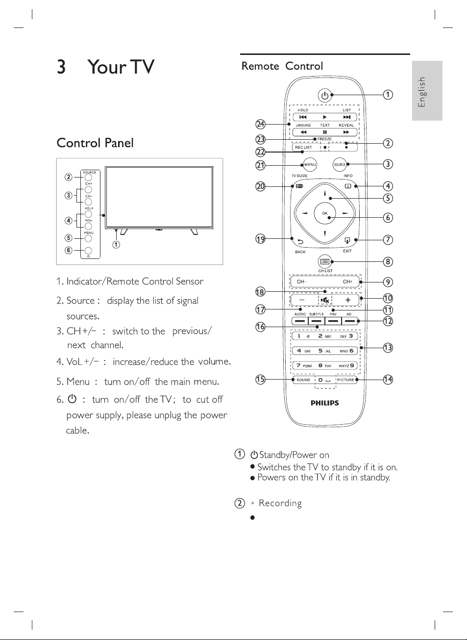
Steps of Recording:
1. Connect the U SB disk to the TV
set to sto re recorded conte nts;
Page 13
2. Select the digital program to be
recorded. Press the Record button
(red dot) on the remote control;
you will see a recording toolbar
indicating that the program is being
recorded at the lower par t of the
screen;
3. Select the Stop button on the
recording toolbar with the remote
control; the prompt "Do you wish
to stop recording?" will pop up.
Select "Yes" to exit from the cur rent
recording or "No" to continue
recording;
4. After the recording is finished, the
recorded contents will be
automatically saved to the USB.
Press REC LIST button on the
remote control to quer y the list of
recorded progr ams.
5. Under the REC LIST interface,
press the "Up" or "Down" button on
the remote control to select a
recorded progr am in the list, and
press the "OK" button to play it.
Steps of S chedule a Recordi ng:
1. Press the "TV G UIDE" butt on
on the rem ote control to disp lay
programs to be playe d on
diffe rent TV chann els and during
diffe rent time per iods on the
cur rent today a nd in the next 7
days;
2. Press the "Up" or "Down" button
on the rem ote control to sele ct a
channe l and then press the "R ight"
button on the remote c ontrol to
enter th e selection inter face for
programs to be playe d during
diffe rent time per iods;
3. Press the red button (Rec ord
button) on the remot e control
continuously to star t recordi ng;
diffe rent functi on icon prompts
will be sh own.
R = Record ing (record once)
D = Daily (record during a
cer tain time per iod ever yd ay)
W = Week ly (re cord during a
cer tain time per iod of a
cer tain day ever y week)
A = Auto recordin g (record
automa tically ac cording
to sched ule change of
programs)
4. Press the "RE C LIST" on the
remote c ontrol. After an
interf ace is shown, press the
"Left /R ight" butt on to display
the prog r ams to be recorded
dur ing differ ent time periods
in the Sch edule List and the
prompt s for different record ing
catego r ies.
Note:
The USB of FAT32 format must be used.
The USB of NTFS format does not
suppor t recording. . The duration of each
recording should be no longer than
6 hours.
12
Page 14
13
Page 15
14
Page 16
15
Page 17
16
Page 18
open.sourc e@t pvi sio n.c om
17
Page 19
18
Page 20
Document:After-salesMaintenanceServiceManualNo.:T7**
Version:
3.0Effectivef rom:March15th,2010
Pageof14KTC
KTC
KTC
KTC
1
After-salesMaintenanceServiceManual
Date:March
2010
Troubleshooting
Troubleshooting
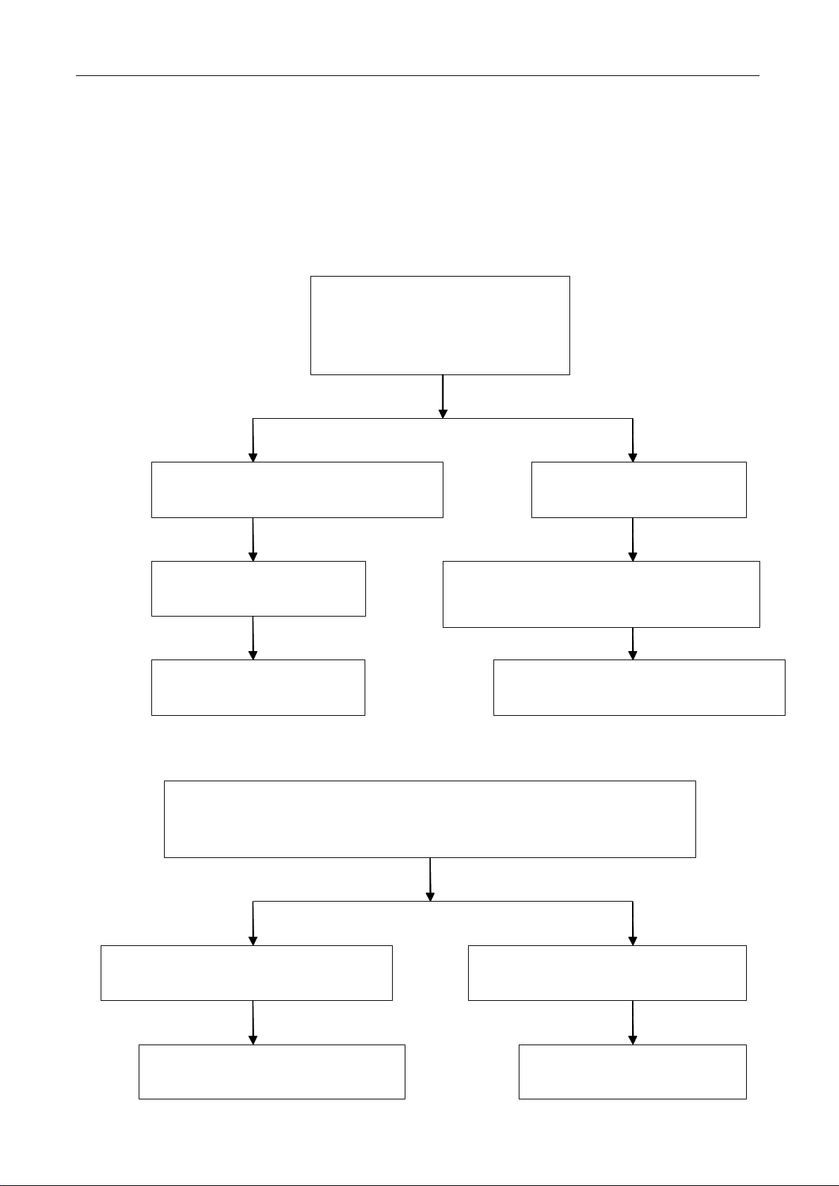
TroubleshootingProcedure
Troubleshooting
4.
1.
No
1.
1.
1.No
power
No
power
Nopower
power
YESNO
Procedure
Procedure
Procedure
Check220Vpowersupplyvoltage
andthecontactofpowersocket
CheckAC(220V)voltageandthe
contactofCN101socket.
Check+5Vand+12Voutputfrom
embeddedpowersupplyforabnormity
YESNO
Check+5Vand+12Von
mainboardforabnormity
YES
Checkforopen-loopoffuse,
orreplacemainboard
2.
Without
2.
Without
2.
2.Without
Withoutlight
light
light
light
Whentheindicatorisonbutthereisnodisplay,checkremotecontrolfor
power-off,minimumbrightness,contrastratio,checkhigh-voltageswitchboard
controlledbymainboardforabnormity
Replacepowercordorpower
socket
Abnormaloutputvoltage+5Vand+12Vfrom
embeddedpowersupply,replaceembedded
powersupplywiththesamemodel
NO
Checkmainboardofpowersupplyfor
looseness,open-loopandpoorcontact
YES
Checkthefuseonhigh-voltageboardfor
thesupplyof12V
YES
Replacehigh-voltageswitchboardCheckfuse
19
Checkeachtriodeofcontrolpartfor
abnormityorreplacemainboard
NO
NO
Page 21
3.
Protection
3.
Protection
3.
3.Protection
Protectionor
after
after
after
afterthe
or
without
or
without
orwithout
withoutlight
the
emergence
the
emergence
theemergence
emergenceof
light
(refers
light
(refers
light(refers
(refersto
of
image)
of
image)
ofimage)
image)
Theimagedisappearedimmediatelyafterthe
emergence;checktheplugofhigh-voltageswitchboard
forstrikingsparksandpoorcontact
to
the
to
tothe
disappearance
the
disappearance
thedisappearance
disappearanceof
of
image
of
image
ofimage
imageseveral
several
several
severalseconds
YES NO
seconds
seconds
seconds
Noproblemsidentified,replacehigh-voltage
board;ifthefaultremains,checkthecontact
lineofbacklightofLCDforanydamage,and
replaceLCDboard.
4.
White
4.
White
4.
4.White
Whitepanel
panel
panel
panel
Whitepanelreferstothebacklightworks
withoutvisiblesignalandjustshowwhite
screen.Checkthevoltageofsocketforflat
cableconnectingthemainboardtoscreen
forabnormality
Ifthereissparkstriking,
replacehigh-voltageboard
YESNO
Checktheinterfacebetweenmainboard
andconnectlineforanylooseness,
shedding,ifnoabnormityexisted,
replaceLCDscreen
20
Checkthepowersupplychipof
controlscreenorreplacemain
board
Page 22
5.
White
5.
White
5.
5.White
Whitescreen
no
no
no
nosignal
screen
screen
screenafter
signal
signal
signalinput,
YESNO
after
power
after
power
afterpower
power-
input,
input,
input,the
Checkwhetherthereischangeofvoltageatthehighvoltage
boardcontrolledbymainboardwhenpower-onandpower-off
the
the
thescreen
-
off
-
off
-off
off(work
screen
screen
screenshows
shows
shows
showsa
(work
(work
(worknormally
normally
normally
normallywhen
a
white
a
white
awhite
whitescreen)
screen)
screen)
screen)
when
power
when
power
whenpower
poweron,
on,
on,
on,but
but
when
but
when
butwhen
whenpower
power
power
power-
-
-
-off
off
or
off
or
offor
or
Checkwhetherthevoltagechangeofthecontrolpinson
thepluginterfaceofhighvoltageboardisnormalwhen
power-onandpower-off
Thecircuit
relatedto
highvoltage
boardispoor
6.
TV
6.
6.
6.TV
without
TV
without
TVwithout
withoutchannel
Checkwhetherthelines
betweenmainboardandhigh
voltageboardisinopen-loop
orpoorcontact
channel
channel
channelor
or
with
color
or
with
orwith
withcolor
CheckTVantennaplugforloosenessand
poorcontact
cast
color
cast
colorcast
cast
Checkwhetherthevoltageofthepinonmain
controllingtheworkingvoltageofhighvoltageboardis
normalwhenpower-onandpower-off
YES YESNO NO
Checkrelevantcircuitsof
highvoltageboard
controlledbymainboard
Replacepoormain
chipsorrecopy
software
chip
Ifwithcolorcast,checkthesettingof
colorsystemundermenu;andchange
ofcolorsystemtoseewhetheritis
normal(Usuallysettoautomatic)
NO
Checktheantennaanditssignal
source,ifnoproblemsexist,replace
tunerorcontrolchipswiththesame
model
YES
Replaceantennaplug
21
Page 23
7.
Poor
7.
Poor
7.
7.Poor
Poorsound
sound
sound
sound
Poorsoundreferstowithoutsoundorwithnoise;check
whethertheselectionofsoundsystemisproper
YES
Switchtootheraudioinput,checkwhetherDVD
inputandPCmainboardinputhassound
NO
Nosoundforotherinputs;checkthesound
amplifierandthesharedcontrolcircuitThereissoundforotherinputs,
8.
No
VGA
8.
8.
8.No
No
VGA
NoVGA
VGAinput
input
input
inputsignal
signal
signal
signal
VGAsignalinputdoesnotrespond,thescreen
prompts“Pleaseinputsignal”,checkwhetherPC
signalsourceandsignallineisnormal.
NO
Nosound;checkwhetherremotecontrolmuteis
selectedandswitchsoundsystem
YES
replaceTVtunerorcontrolchip
CheckVGAsignalinputboardandseewhethertherow
andfieldsyncsignalprotectiondiodeisbrokedown
NO
Replacethemotherboardor
factoryresetisnormalReplacethe5.6VZenerdiode
22
NO YES
ReplacePCorsignalline,check
displayVGAplugforlooseness
YES
onthemotherboard
Page 24
9.
Poor
9.
Poor
9.
9.Poor
Poorembedded
embedded
embedded
embeddedpower
power
power
powersupply
Poweron,checkembeddedpowersupply5VSBinTVfor5Vvoltageoutput
supply
supply
supplyof
of
of
ofTV
TV
TV
TV
YES
Highelectricallevelexistedat
STB(higherthan2.5V)
YESNO
Check+5V,+12V
fornormalinput
NO
Replacepowersupply
Checkpowersupplylineforlooseness,checkindictorfor
workingandpowersupplysocketforlooseness
CheckEC2for380-400V
voltage;ifthereisnot,
replacepowersupply
YES
Fastenlines
andsocket
NO
NO
Replacepower
supply
10.
Common
10.
Common
10.
10.Common
Commonfault
fault
fault
faultof
of
LCD
of
LCD
ofLCD
LCDscreen
screen
screen
screen
10.1Brightlineorbrightbelt(BL):constantlongitudinalortransverseilluminatinglineor
beltduetonon-conformedconnectionbetweenICandglass
10.2Darkline(DL):constantlongitudinalortransverseilluminatinglinedueto
non-conformedconnectionbetweenICandglass.
10.3Whitepanel(WP):onlylighttubeilluminatesowingtonon-conformeddriveplateof
theLCD,withoutanydisplaysignalinthedisplayarea,andthewholescreeniswhite.
10.4Screenbreaking:(overflowofLCD):withdamageorinvisibledamageoftheliquid
crystalglass,irregularblackdefectoccursfromliquidcrystalbodytoglassandpolarizer,
whichcannotbeseenatanyimage.Theoverflowportioncannotformimageanddoesnot
display.
10.5PressingScrape(PS):afterlocaldisplayareaatthefrontofLCDisheavilypressed,
23
Page 25

glassofthepressedportionisnotdamaged,theliquidcrystalbodycannotdisplaynormally,
withspotorblockblackdefect.
10.6Screenmess:irregularcolordisplayarisingfromdamageofdrivingplateinLCD.
24
Page 26
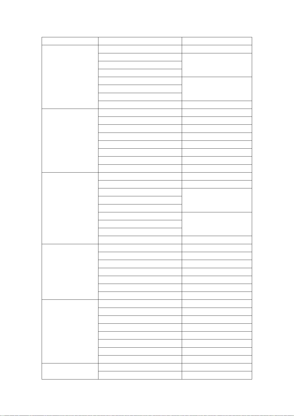
Factory menu entry: Press MENU, and then press 1999
Primary menu Secondary menu Value,remark
MDOE VGA,YPBPR,Selection
R-GAIN
G-GAIN
ADC ADJUST
PICTURE MODE
W/B ADJUST
SSC SETTING
Spectial set 2HOUR OFF 2hours power off enable
VIF Vif 1 Vif set
B-GAIN
R-OFFSET
G-OFFSET
B-OFFSET
AUTO ADC ADC automatically adjust
Input Source Source Selection
MODE Dynamic/Standard/Sotf/User
BRIGHTNESS BRIGHTNESS
CONTRAST CONTRAST
COLOR COLOR
SHARPNESS SHARPNESS
TINT TINT
Copy all No function
inputsource Source Selection
TEMPERATURE Cool, S t andard, Wa rm
R-GAIN
G-GAIN
B-GAIN
R-OFFSET
G-OFFSET
B-OFFSET
Copy all No function
MIU Enable DDR spectrum enable
MIU0 Span Exhibition frequently wide
MIU Step Spread spectrum step
LVDS enable LVDS spectrum enable
LVDS Span Exhibition frequently wide
LVDS Step Spread spectrum step
LVDS swing LVDS swing
WDT Watch dog on/off
White pattern White pattern selection
Restore user default Factory reset
PVR_RECORDALL PVR Record on/off
Power Power mode selection
Mirror Mirror function selection
Ageing mode Ageing mode enable
Vif 2 Vif set
Front-end gain adjustment
Clamp level adjustment
White level adjustment
Black level adjustment
25
Page 27
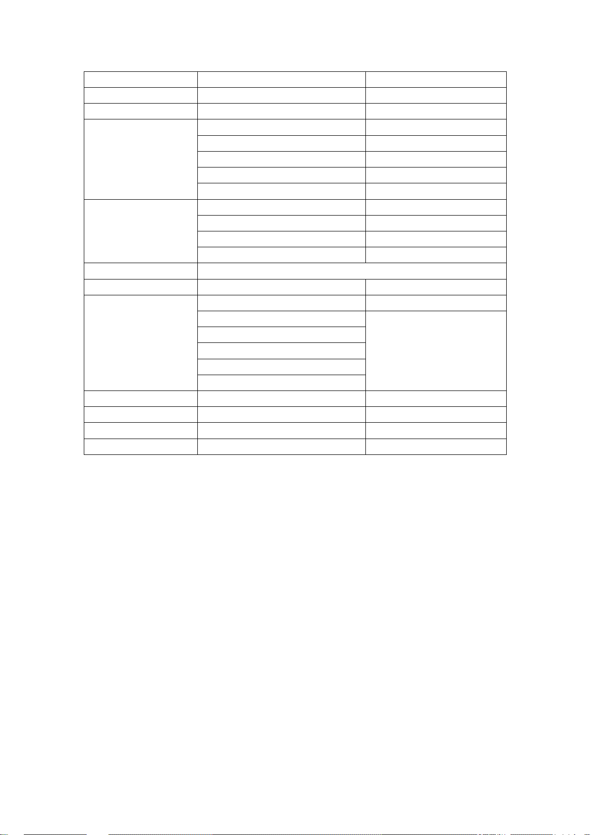
Vif 3 Vif set
Qmap adjsut PQ setting
PEQ PEQsetting
OverScan Overscan_resolution Reselution select
Overscan_hsize Adjust overscan H size
Overscan_hposition Adjust overscan H position
Overscan_vsize Adjust overscan V size
Overscan_vposition Adjust overscal V position
other Test pattern
UART DEBUG DEBUG ON/OFF
HDMI CEC/ARC CEC/ARC ON/OFF
Backlight Adjust backlight
CI+ key usb upgrade CI+ key usb upgrade
SW information SW information
MODE Feature Selection
OSD 0
Non-linear
Channel table1 KTC factory Frequecy table set
CI factory setting No function
Channel table2 KTC factory Frequecy table set
Channel dvbt KTC factory Frequecy table set
OSD 25
OSD 50
OSD 75
OSD 100
Curve adjustment
26
Page 28
MSD3463 software upgrades (After Service)
e
1 Software upgrade tools and materials
、
u AC100~240V power supply and power cord
u USB flash disk(2.0 version,Capacity not more than 4G)
2 Preparatory work before the upgrade
、
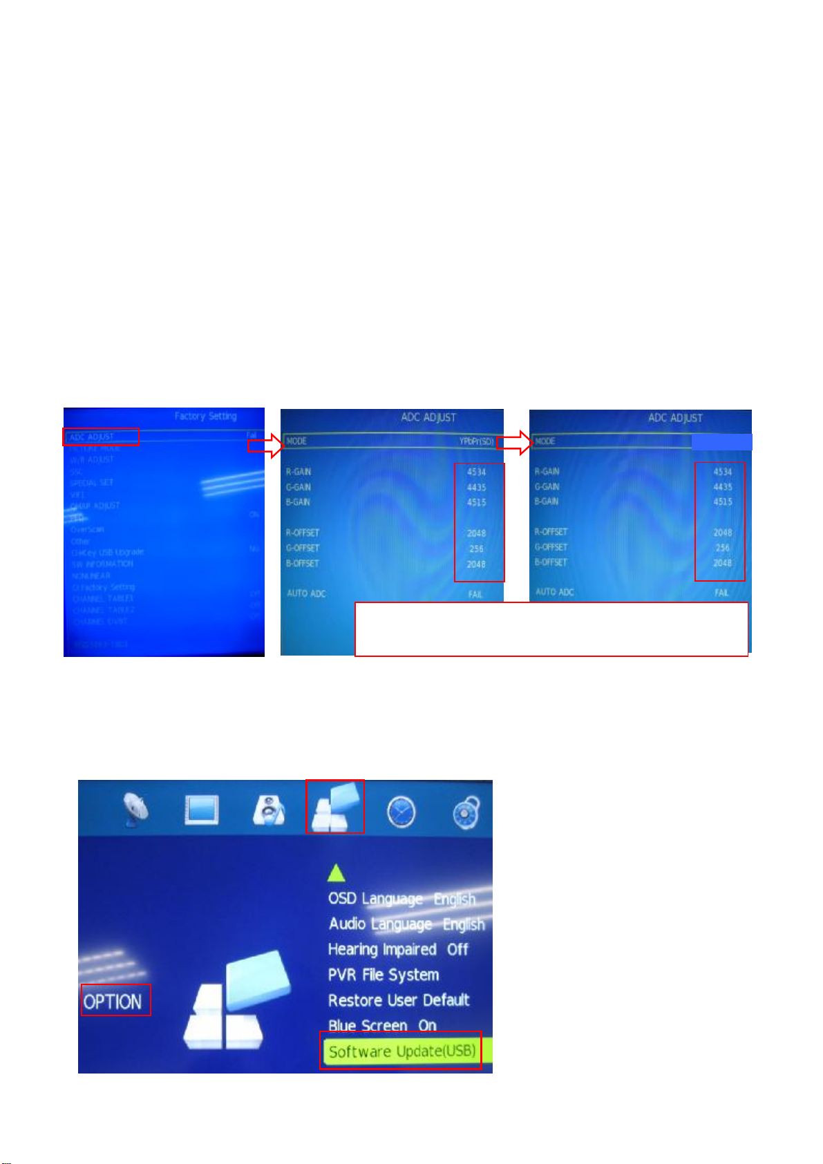
Recorded all the ADC and the white balance data of all the message source in factory menu before
upgrade(FLASH initialization may occur after theupgrade,flushcolor calibration data, then restore the data you
have been recorded):
1. In the condition of YPbPb message source, press the MENU button after appear the main menu, then
2. IntheADC ADJUST item, press OK key to enter the next level menu, move the cursor to the MODE item,
3. Operations and procedure of software upgrading:
3.1. Changed the file name to "MERGE.bin", then stored software in the FAT32 format blank U disk.
3.2. Insert USB flash disk into the USB upgrade port, upgrade the software according to the following the operating
instructions:
press up or down key to get into Software Update(USB), press right key or OK key to enter.
followed by number keys to enter the factory menu, select ADC ADJUST item, press the OK key to
enter the next level menu, move the cursor to the MODE item, press the left / right Moving button and
move the cursor selection in YPbPr (SD)item, record the R-GAIN/G-GAIN/B-GAIN value and
R-OFFSET/G-OFFSET/B-OFFSET value.
1999
press the left / right cursor keys to select YPbPr (HD) item, record R-GAIN/G-GAIN/B-GAIN value and
R-OFFSET/G-OFFSET/B-OFFSET value.
YPbPr(HD)
Record the R/G/B-GAIN and R/B/G-OFFSET value under th
YPbPr(SD) and YPbPr(HD) mode, to be replaced the recorded value
after the machine software upgrade
press MENU key on remote controller , press left or right key switching to OPTION after prompting to the next menu, then
27
Page 29
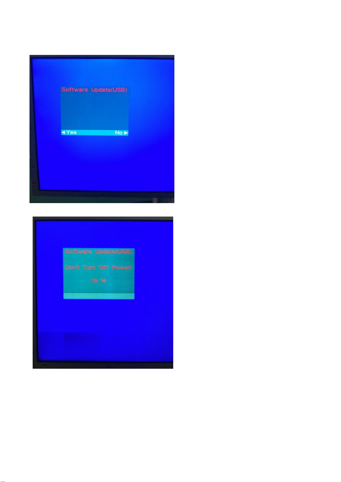
Software update menu will pop up when press confirm key, then select “Yes” to confirm:
The process of software updating:
Method 2:Keep pressing VOL+ key on the machine panel, power on the machine, the standby light flashes quickly after
about 5 seconds, standby light extinguish and turn into lighting after about a minute, means that the upgrade is completed.
3.3. Notice:
①. When the machine Upgrading (U disk light flash), do not remove U disk or switch off the power, otherwise it will
destroy the software and lead can not upgrade.
②. The machine must be power off when inserted or pulled out U disk, to avoid U disk or damage the machine.
4、When cannot upgrade in accordance with the step two, or upgrade failed, can only ISP upgrade, please refer to the
28
Page 30
following instructions.
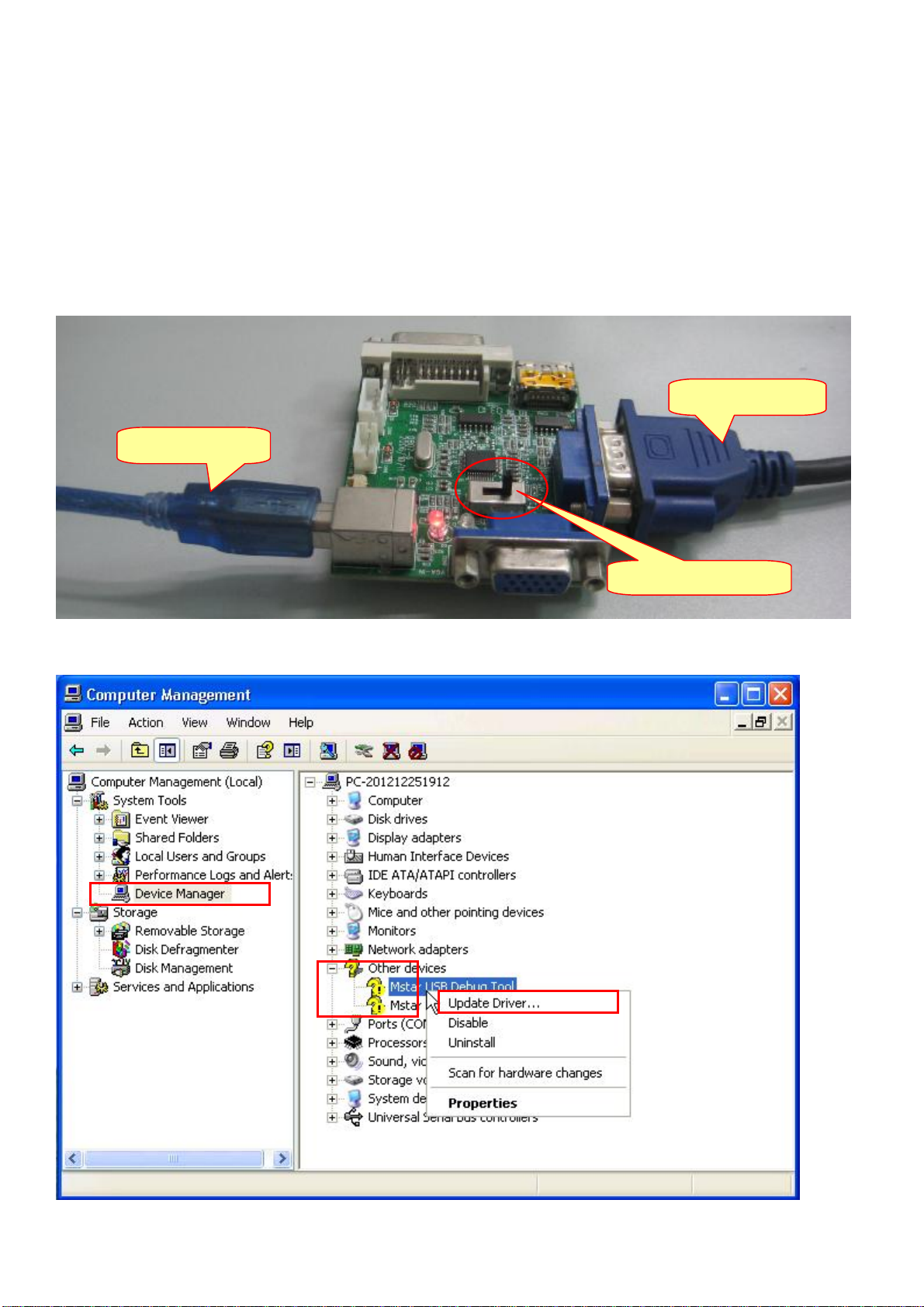
ISP to upgradetools and materials (When mainboard can not use USB interface to upgrade):
* Personal computer (WINDOWS XP system,USB2.0)
*AC100~240V power supply and power cord
*Drivers for ISP burning board ISP
*ISP_Tool_474.exe
*VGA cable
(1). Connect the ISP burning board and TV VGA port with VGA cable.
To computer USB
To VGA interface
Direction of switch
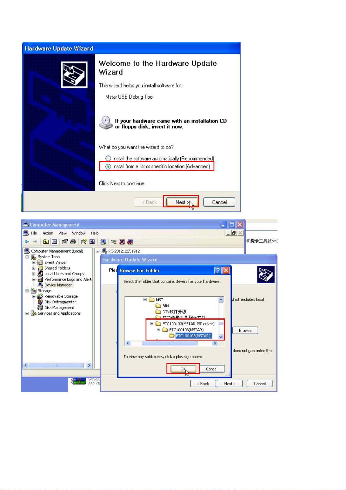
(2). Insert the Mstar USB Tool into the USB port of your PC. The PC can recognize the new device. You can choose to
install it in the list, or choose to install at a specified directory and specify the path to the drive file. See the figure below:
29
Page 31
30
Page 32
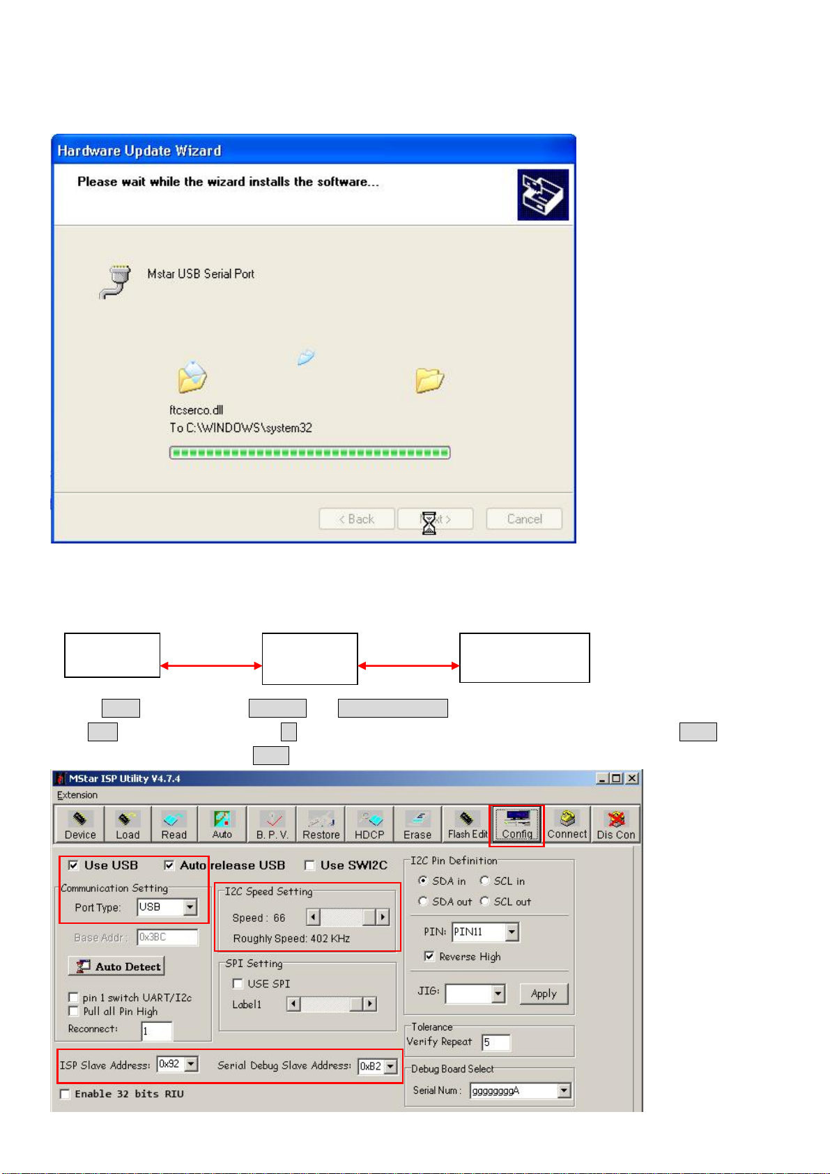
(3) When PC finds the drive file, it will give the prompts as in the figure below during the installation process. Please
click “Continue" to go ahead. The system will go through three drive installation processes, including Mstar USB Debug
Tool A, Mstar USB Debug Tool B, and Mstar USB SerialPort. They will be installed one by one.
Software burning
a.When the drives are installed, connect the Mstar USB Tool board to TV main board in the following way. Then connect
the power cord and run the software ISP-Tool V4.7.4.exe.
Computer
USB cable
ISP burning
board
VGA cable
TV mainboard
VGA interface
b.In the config menu bar, select Use USB and Auto release USB,Port Type under the Communication Setting items
select USB。Set the burning speed of 28 in I2C Speed Setting item, ISP Slave Address item menu select OX92,Serial
Debug Slave Address menu select 0XB2。
31
Page 33
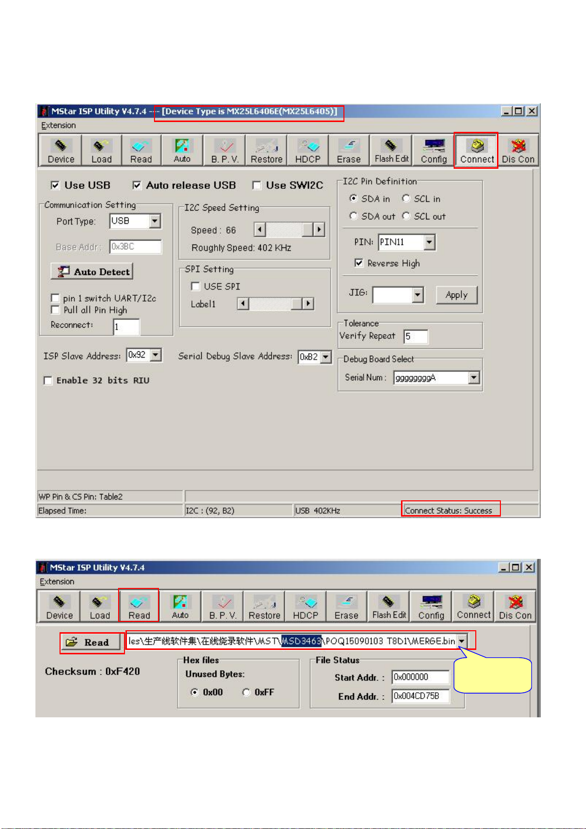
c. Click Connect button, If it prompts "Device Type is ******" means that connect normally; If it prompts "Program File
Not Ready!" means that there is poor connection, please have a check.
d.Click "Read" button, then click "Read" button again to load the current mainboard software.
e.Click "Auto" button, then set it according to the following figure.
The file’s suffix
must be .bin
32
Page 34
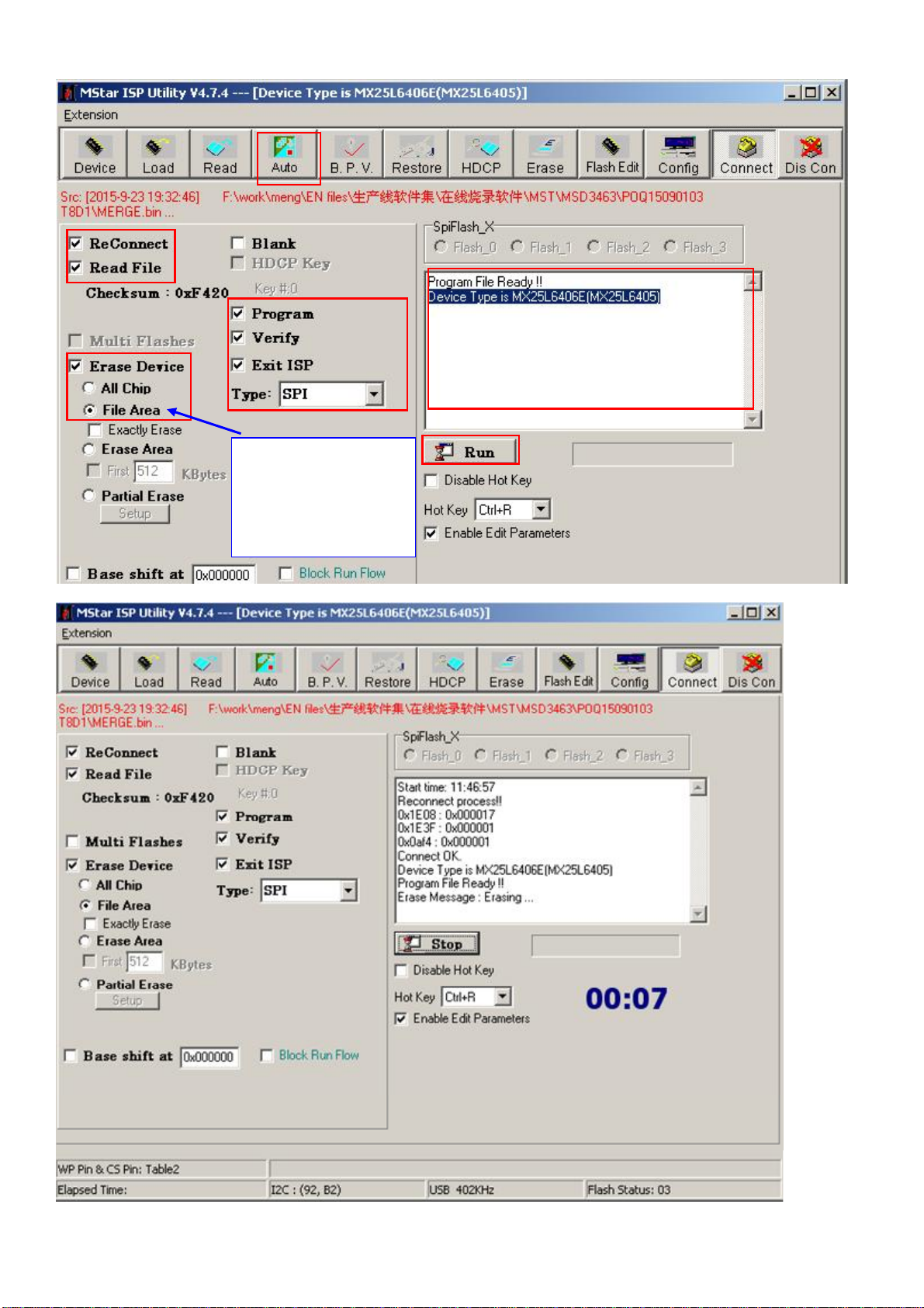
If select All Chip option
carelessly and execute
loading action, it will erase
CI+KEY on mainboard. So
CI+ KEY must reload after
software upgrading.
Status bar
f.Then press "RUN" button to burn software.
When display “PASS” after burning, means that software has burnt successfully.
33
Page 35
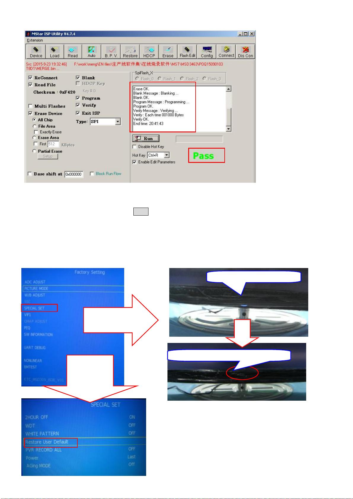
Never plug or unplug the connection lines in the burning process. Please turn the power switch to “Off” when installing
ISP board. Pull out the power cord from the machine and then pull out the burning adapter from the machine, when
burning completed, change the TV and click Run button to burn next machine.
5.When upgrade complete, install the machine back cover, then must be adjusted before leave factory:
(1). Power to the machine, press MENU button on the remote control to popping the main menu, press 8202 number
keys and then will popping the factory menu automatically, move the cursor to the "SPECIAL SET" option, press the
remote control OK key to enter the next level menu, select "Restore User Default" in SPECIAL SET submeun, press OK
key and the machine will black screen and restart after about 8 seconds, complete the reset action.
Panel standby light bright, resetting
Press OK key on remote
control to implement
factory reset
Panel standby light extinguish, reset completed
Press OK key on
remote control to
implement factory
reset
34
Page 36
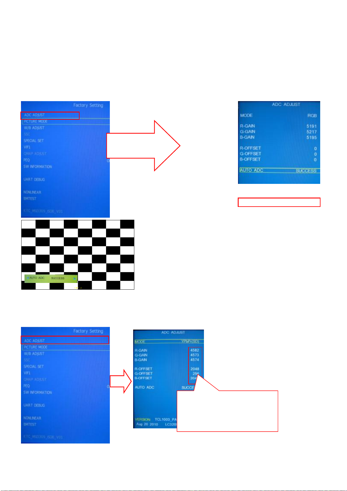
(2). Insert signal cable to the machine, switch to the PC message source.
(3). Run the KTC-LCD test software, switch to the mosaic picture and best resolution. Press MENU key to popup the
main menu, and then press 8202 number keys to enter the factory menu, press the shift douwn key to ADC ADJUST
option to press OK key to enter the next level menu. In the MODE option press left/right cursor keys to select RGB, and
then press shift douwn key to move the cursor to the Auto ADC option, press OK key to enter the next level menu, press
the left/right button to implement ADC action (The screen will flash and Auto ADC function menu prompt SUCCESS
means that debug success, prompt FAIL said that debug failed, try again), press the MENU button to exit factory menu
when debugging completed.
Press OK key on remote
control to implement
factory reset
(4). Under the YPbPb message source, press the MENU button after popping the main menu, then press 8202 number
keys to enter the factory menu, select ADC ADJUST item, press the OK key to enter the next level menu, move the cursor
to the MODE item, press the left/right Moving key mover cursor to select YPbPr(SD)item, change the
R-GAIN/G-GAIN/B-GAIN value and R-OFFSET/G-OFFSET/B-OFFSET value of the machine after the upgrade to the
value before the upgrade.
Change the
R-GAIN/G-GAIN/B-GAIN value and
R-OFFSET/G-OFFSET/B-OFFSET
value to the value before the upgrade
under the YPbPr(SD/HD) mode
(5). In the ADC ADJUST item, press OK key to enter the next level menu, move the cursor to the MODE item, press the
left/right keys tomove cursor select the YPbPr(HD)item, change the R-GAIN/G-GAIN/B-GAIN value and
R-OFFSET/G-OFFSET/B-OFFSET value of the machine after the upgrade to the value before the upgrade.
35
Page 37
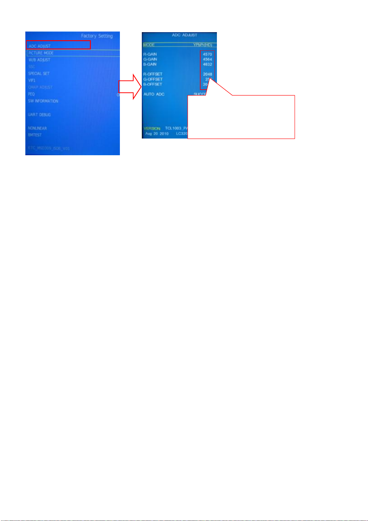
Change the
R-GAIN/G-GAIN/B-GAIN value and
R-OFFSET/G-OFFSET/B-OFFSET
value to the value before the upgrade
under the YPbPr(SD/HD) mode
(6). Complete the ADC ADJUST debugging, press MENU key succession to exit the factory built-in menu to save the
adjusted data, and then restore the original packaging.
36
Page 38
1
2
3
4
5
6
Power Board Circuit Diagram
8A/600V
D201
U201
47R
RJ44
0R
R212
16K
R218
7
240K
C402
222/400V
D403
2.2R*4
T301
U403A
1
2
104/50V
C419
32
R412
6
2
R213
0R
RJ20
0R
EFD45
PC817
750K
R413
RL207
1
R437
Q407
1
R431
L205
C208
104/250V
R214
R215
750K
1M
R210
20R
R216
200R
Q202
2907
R207
300R
T402
2
4
7
6
EFD20
R418
100R
R419
100R
32
Q401
3A/650V
47R
R415
R414
H303
3
2
1
3PIN
RJ5
0R
R432
2K
D411
LL4148
2222
C420
4.7K
104/50V
3
4 5
PQ38 269uH)
R201
1M
R202
1M
R203
1M
RJ1
0R
D406
C409
C407
103/50V
12V
C203
103/50V
R417
Q403
14V
5.1K
D409 15V
R315
R317
C309
R319
105/50V
C408
104/50V
0R
VC_LLC
R205
20K
PC817
RT
10R
L203B
V_BUS
Q402 2SA684
C410
U403B
47UF/50V
U402
1
2
3
OB2273B
R316
D307
LL4148
D306 LL4148
10R
R320
D303
R313
75R
D410
LL4148
4.7K
GND
FB
RI
47R
1N4148
5VSB2
R429
C205
105/50V
R416
R436
1K
4.7K
3
4
3
SENSE
V_BUS2
47R
225/25V
VC_PFC2
8
MU
5
13
RJ11
0R
C421
10UF/450V
RJ9
0R
100UF/50V
GATE
VDD
RJ22
R318
10K 1206
R321
10K
D304
1N4148
R428
2k
C204
VCC
ZCD
R206
62K
C403
R314
L203A
1
1
100R
23
6
5
4
V_BUS
0R
C418
104/50V
C206
474/50V
2
COMP
GND6CS
D402
LL4148
R408
10R
RJ10
0R
RJ21
32
Q301
10T60
10T60
32
Q302
C310
101/1KV
Q405
2907
1
1
R204
10K
R410R409
D415
R434
D401
RM07
R435
C405
101/50V
0R
32
Q406
2222
1
GD
4
R411
300R
R430
INV
4.7K
MP44010
C207
100PF/50V
LL4148
103/1KV
C311
A A
AC+
R1031MR104
R1011MR102
C103
102 Y1
L101
18*10 8mH
B B
F101
T5.0AH 250VAC
C C
2.0M
R303
C305
472/50V
D D
R426
12V
D408
LL4148
5VSB
Q404 3014
V102
241
241
J101
C301
C302
R301
C303
C304
1
C102
0.22uF/275V
2
CY3
471
R302
4.7K
R304
8.2K
1M
R427
240K
1
560V
3
L102
18*10 8mH
1M
1M
C104
102 Y1
3
C101
0.22uF/275V
V101
560V
1
105/25V
105/25V
1M
104/50V
330PF/50V
D301
817C
23
AC-
1N4148
RJ23
0R
R306
4.3K
U301B
C416
224/50V
C417
470uF/16V
R305
4.3K
V_BUS2
5V
R311
51K
3 2
AC+ AC-
AC-
R401
3M
R402
3M
R403
3M
R404
390K
R4051MR4061MR407
AC-
1
2
3
4
5
6
7
R331
8 9
3M
R308
3M
R309
3M
R310
0R
R312
NC
C317
103/50V
+12V
R323
1K
R324
2K
U301A
817C
R327
U303
3.3K
TL431
RJ8
C401
104/50V
U302
Css
Delay
CF
RFmin
STBY
ISEN
LINE
DIS PFC-STOP
HR1000A
R325
1K
R328
L204
100uH
C201
14
B201
8A/600V
D405
0R
LL4148
RT
1M
D404
22V
VBOOT
HVG
OUT
NC
Vcc
LVG
GND
+12V +12VSB
C316
47NF/50V
R326
R329
11K
4.3K
C202
474/450V
224/450V
RJ12
0R
16
15
14
13
12
11
10
VC_PFC1
U401B
PC817
C312
K01
D302
68K
+12V
15V
RJ38
0R
L8050PLT1G
4
3
104/50V
R322
10R
105/50V
36V
4.7UF/50V
D305
18V
C308
2
1
R211
10K
2.2R
R217
R209
0.2R 3W
10
9
8
C404
NC
1
1
10
1
8
1
D308
H302
13
14
D309 20A100V
2
16
1
15
11
12
ADJUST
D310
2PIN
PS_ON
RJ17
0R
RJ18
C209
82uF/450V
32
Q201
20N600
VC_PFC1
RJ2
0R
RJ3
0R
R208
VC_LLC
0.2R 3W
C412
C411
1000uF/16V
1000uF/16V
D413
SR560
D407
SR560
D412
SR560
R420
1K
C414
102/200V
PC817
U401A
1
R421
C415
2
104/50V
U404
TL431
H301
1
2
2PIN
+12VSB
2
680uF/25V
2
680uF/25V
1
2
3
C314
470uF/50V
123
H304
3PIN
15pin
1414131312121111101099887766554433221
15
J301
15
12V
BL-ON
RT201
6A/2.5R
L401
C313
C318
3uH
L301
3uH
C210
82uF/450V
VC_PFC2
NC
1K
R422
R425
43K
C315
5V
5VSB
R330
10K
470uF/50V
V_BUS
L302
PS_ON
1.8uH
C413
470uF/16V
5VSB
RJ6
0R
RJ7
0R
5VSB2
R423
3.3K
R424
3.3K
36V
12V
H201
1
PGND
C319
470uF/25V
1
+12V
RJ30
C501
104/50V
C513
105/50V
C502
GATE2
105/50V
RJ16
5V
0R
R525
V_REF
U502
AZ431
LED1 LED2
D505
3
BAV99
1
2
Vcmp Vcmp
Vsp Vsp
U501
AP3041
1
CT
FLAG
2
OV
R526
1K
Vcmp
3
4
5
6
7
D506
BAV99
2
2.2uF/10V
FAULT
RJ4
R530
UVLO
EN
SS/COMP
VIN
VCC
OUT
GND8FAULT
Q503 2N7002
3 2
1
R527
1K
C511
0R
200K
Q504 2222
R531
33K
FB
R532
20K
LED3
3
1
Vcmp
PWM
D507
BAV99
2
Vsp
FB
SC
CS
RT
OVP
UVL
EN
10K
7.5K
RJ37
0R
3
1
R501
16
15
PWM
14
FB
13
R502
12
11
CS2
R503
10
270K
9
FAULT
R528
R529
Q505
2N7002
1K
R533
R534
D511
6.8V
LED4 LED5
D508
3
BAV99
1
2
Vcmp Vcmp
Vsp Vsp
51K
20K
100R 1206
100R 1206
AZ431L
R535
20K
1
U503
1K
36V
R505
270K
10K
R504
C504
224/50V
C503
473/50V
OVP
Vsp
3
2
C512
D509
BAV99
101/50V
Vcmp
R517
CS2
75R
C509
471/50V
R536
V_REF
1K
R565
3.3k
SENSE
LED6
ADJUST
D510
3
BAV99
1
2
Vsp
L501
200uH
0R
RJ34
UVL
R506
10K
GATE2
LED1 LED2 LED3
RJ43
Q506
2SD669AC1
13R
R537
R561
10K
R507
RJ33
10R
0R
RJ36
0R
R518
R36
RJ29
0R
0R
R538
13R
13R
R539
R540
RJ26
0R
RJ41
NC
RJ31
0R
PWM EN
R562
510K
33R
LED4
13R
R549
D501
LL4148
Q509
2SD669AC1
RJ19
R564
20K
R519
R36
R550
R563
10K
0R
R508
R541
R509
4.7R
RJ28
0R
Q507
2SD669AC1
R542
13R
RJ25
0R
RJ40
0R
R551
13R
10R
R520
R36
13R
13R
BL-ON
R511
D502
LL4148
R543
13R
LED5
Q510
2SD669AC1
33R
R552
R521
RJ42
R36
RJ27
R553
0R
R544
RJ39
13R
10R
R512
R510
10K
33R
4.7R
NC
0R
R522
R36
13R
R554
RJ35
Q502
AOD4286
Q508
2SD669AC1
R555
LED6
J501
13PIN
KTC机密文件,未经书面许可不得扩散
KTC confidential do not spread without the written permission
12V
本文档仅限中国深圳康冠技术有限公司和被呈送方内部使用,未经书面许可请勿扩散到第三方
版权所有@深圳康冠技术有限公司
This Document for Shenzhen KTC Technology Co.Ltd and presented party internal use only
C320
104/50
Do not spread to a third party without the written permission
Cop yright@shenzhen KTC Technology Co.,Ltd
盖章有效,如因电路改良而变动恕不另行通知
KTC ISO90 01、I SO14 001体 系
文件名称:KTC K-PL-LO3(MP44010+HR1000A+OB2273+AP3041)二合一电源原理图
文件编号:T4235 版本:3.0
设计:徐明 审核 批准
发行部门:研发处 生效日期:2014-06-06
37
4
5
LED5
0R
D503
D504
SR5100
R545
13R
13R
R556
LED4
R513
10K
SR5100
OVP
R523
R36
13R
13R
R546
R547
RJ24
0R
LED6
33R
SENSE
LED3
LED2
LED1
页数:1/1
6
Q501
AOD4286
R515
510K
R516
510K
RJ32
0R
R524
20K
33R
R548
Q511
2SD669AC1
13R
R557
C506
NC
R514
NC
LED+
104/250V
C514
C507
C508
100uF/100V
104/250V
C510
NC
13R
13R
33R
R558
R559
R560
LED+
987654321
131211
10
Page 39
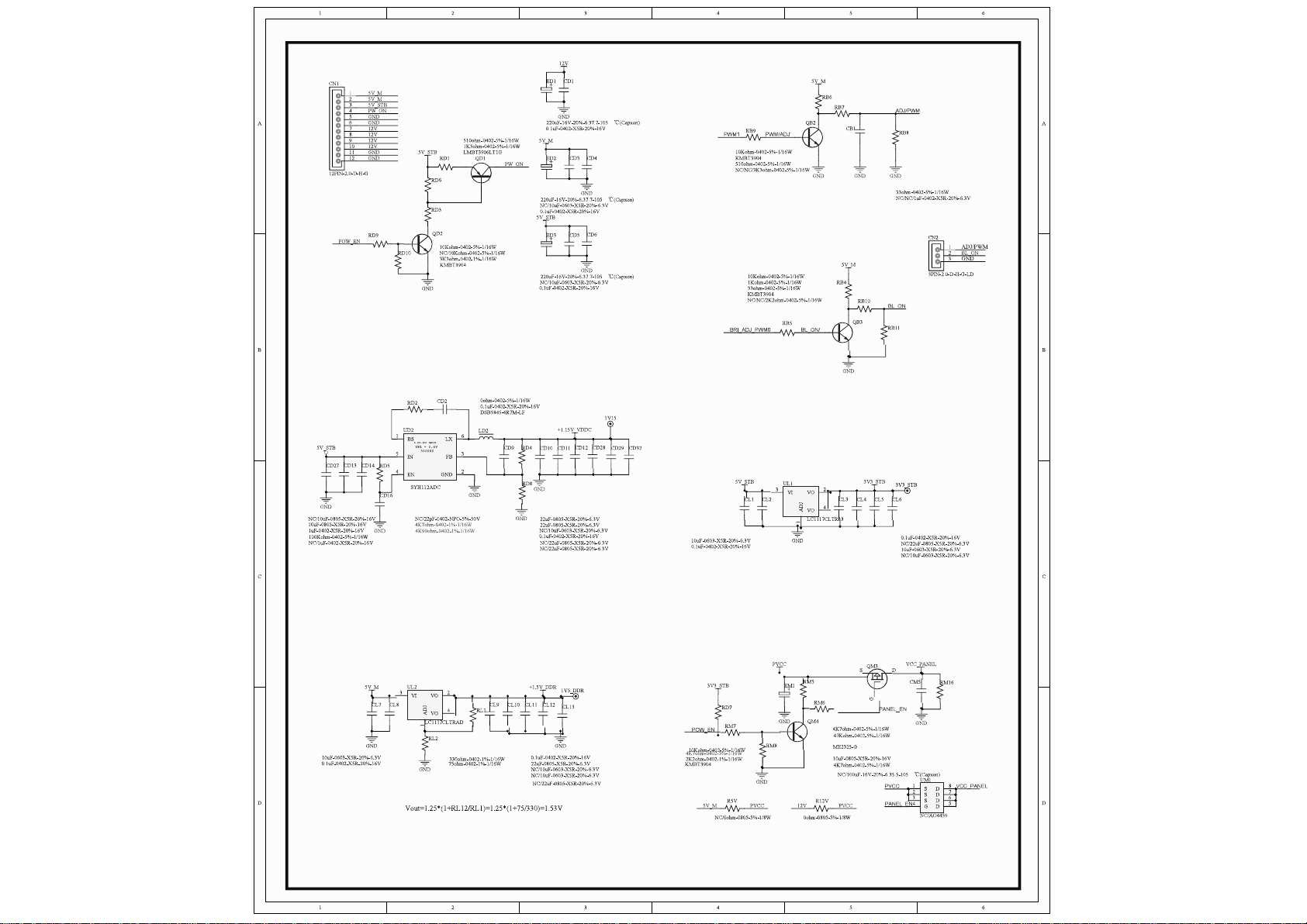
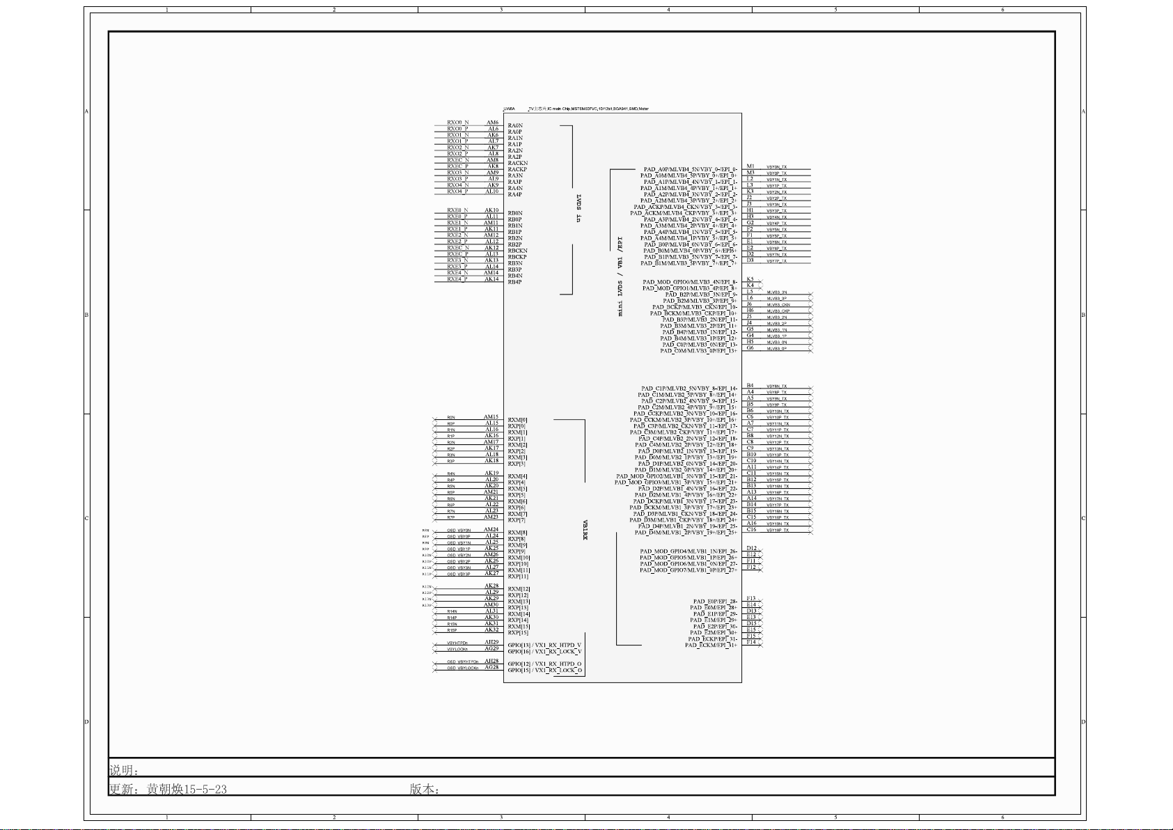
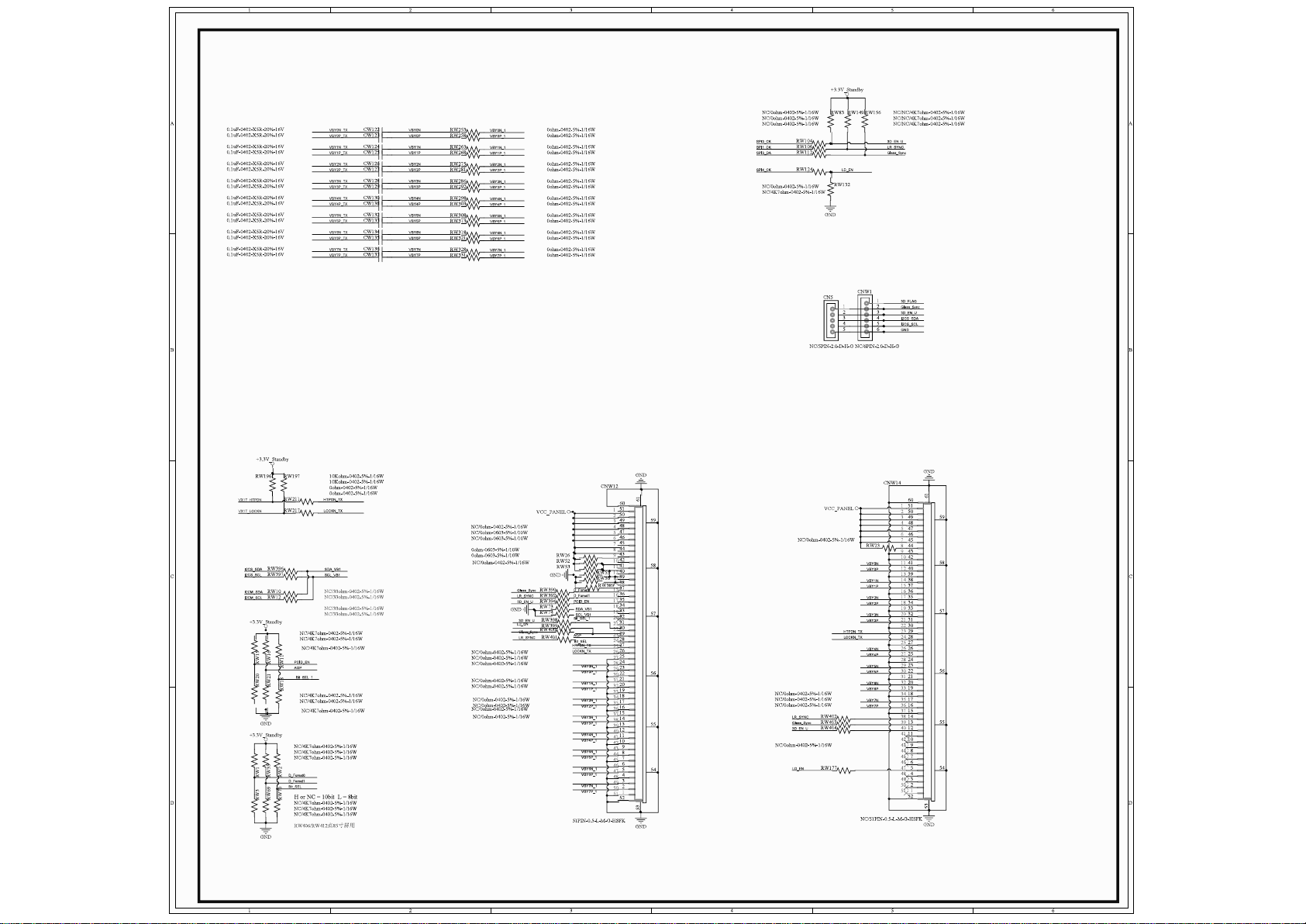
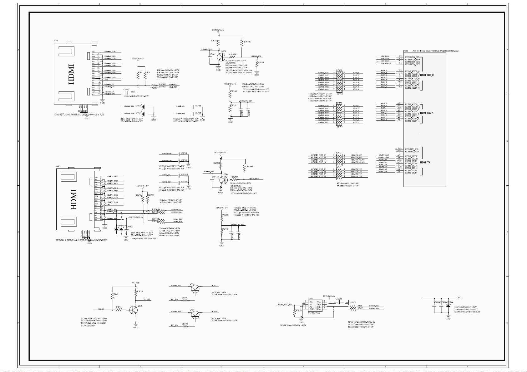
Main Board Circuit Diagram
38
Page 40
39
Page 41
40
Page 42
41
Page 43
42
Page 44
43
Page 45
44
Page 46
45
46
Page 47
Page 48
47
Page 49
484950
Page 50
Page 51
Page 52
51
 Loading...