

Philips 43PUG6102 Schematic
TPM17.9L
Chassis name Platform Model name
43PUG6102/77
43PUG6102/78
50PUG6102/77
TPM17.9L LA MTK5596L
50PUG6102/78
55PUG6102/77
55PUG6102/78
65PUG6412/77
Published by CQZ/SC 1737 Quality Subject to modification 3122 785 20440
© TP Vision Netherlands B.V.
2017
All rights reserved. Specifications are subject to change without notice. Trademarks are the
property of Koninklijke Philips Electronics N.V. or their respective owners.
TP Vision Netherlands B.V. reserves the right to change products at any time without being obliged to adjust
earlier supplies accordingly.
PHILIPS and the PHILIPS’ Shield Emblem are used under license from Koninklijke Philips Electronics N.V.
2017-Sep-15

1.Product inforamtion……….……………………………………………………………………………………3
2.Connections overview……..…..…..………………..…………………………………………………………5
3.Mechanical Instructions………………….…………………………………………………………………….6
Cable dressing (43" 6102 series)………………………………………………………………………………6
Cable dressing (50"/55" 6102 series)…………………………………………………………………………6
Cable dressing (65" 6412 series)………………………………………………………………………………7
Assembly/Panel Removal ………………………………………………………………………………………8
4.Service Modes…………….……………….………………….…………………………………………….….12
5.Software upgrading, Error Code and Panel Code………...……………………………………………..16
6.Circuit Descriptions…..……………………….………………………………………………………………21
7.IC Data Sheet……...……………………………………………………………………………………….…..27
8.Circuit Diagrams……………...……………………………………………………………………………….30
8.1 715G7350 PSU………………………………………………………………………..……………………30
8.2 715G8672 PSU………………………………………………………………………..……………………34
8.3 715G7374 PSU………………………………………………………………………..……………………38
8.4 715G8682 PSU………………………………………………………………………..……………………42
8.5 715G8071 SSB………………………………………………………………………..……………………46
8.6 715G8623 IR/LED Panel………………………………………………..…………………………………68
8.7 715G7088 Keyboard control panel……………………………………………………………………….69
8.8 715G8555 Keyboard control panel……………………………………………………………………….70
9.Styling Sheet……………….…………………….……………………………………………………………..71
6102 series 43"/50"/55"…………………………………………………………………………………….71
6412 series 65"………………………………………………………………………………………………….72
Published by CQZ/SC 1737 Quality Subject to modification 3122 785 20440
© TP Vision Netherlands B.V.
2017
All rights reserved. Specifications are subject to change without notice. Trademarks are the
property of Koninklijke Philips Electronics N.V. or their respective owners.
TP Vision Netherlands B.V. reserves the right to change products at any time without being obliged to adjust
earlier supplies accordingly.
PHILIPS and the PHILIPS’ Shield Emblem are used under license from Koninklijke Philips Electronics N.V.
2017-Sep-15

1. Product information
Product information is subject to change without notice.
For detailed procuct information,please visit
www.philips.com/support
Display
Type
Diagonal screen size
• 43PUG6102: 43 inch (108 cm)
• 50PUG6102: 50 inch (126 cm)
• 55PUG6102: 55 inch (139 cm)
• 65PUx6412: 65 inch (164 cm)
Display resolution
• 3840 x 2160p
Input resolution
Video formats
Resolution — Refresh rate
• 480i - 60 Hz
• 480p - 60 Hz
• 576i - 50 Hz
• 576p - 50 Hz
• 720p - 50 Hz, 60 Hz
• 1080i - 50 Hz, 60 Hz
• 1080p - 24 Hz, 25 Hz, 30 Hz
• 2160p - 24 Hz, 25 Hz, 30 Hz, 50 Hz, 60 Hz
Computer formats
Resolutions (among others)
• 640 x 480 - 60 Hz
• 800 x 600 - 60 Hz
• 1024 x 768 - 60 Hz
• 1280 x 768 - 60 Hz
• 1360 x 765 - 60 Hz
• 1360 x 768 - 60 Hz
• 1280 x 1024 - 60 Hz
• 1920 x 1080 - 60 Hz
• 3840 x 2160 - 60 Hz
• with TV stand:
Width 968.18 mm - Height 628.16 mm - Depth
259.00 mm - Weight ± TBD kg
50PUG6102
• without TV stand:
Width 1129.54 mm - Height 656.45 mm - Depth
83.17 mm - Weight ± 12.80 kg
• with TV stand:
Width 1129.54 mm - Height 717.72 mm - Depth
259.18 mm - Weight ± 13.15 kg
55PUG6102
• without TV stand:
Width 1239.20 mm - Height 714.04 mm - Depth
90.26 mm - Weight ± 15.28 kg
• with TV stand:
Width 1239.20 mm - Height 780.34 mm - Depth
259.06 mm - Weight ± 15.60 kg
65PUx6412
• without TV stand:
Width 1462.3 mm - Height 854.0 mm - Depth
89.3 mm - Weight ± 24.5 kg
• with TV stand:
Width 1462.3 mm - Height 906.7 mm - Depth
271.5 mm - Weight ± 26.2 kg
Connectivity
TV Side
• HDMI 1 in - MHL
• HDMI 2 in
• HDMI 3 in
• USB 1
• USB 2
• 1x Serv.U
• Headphones - Stereo mini-jack 3.5mm
TV Bottom
• CVBS/Y Pb Pr: CVBS/Y Pb Pr, Audio L/R
• HDMI 4 in - ARC
• SPDIF: Digital Audio Out-Optical
• Network LAN - RJ45
• Antenna (75 ohm)
Dimensions and Weights
43PUG6102
• without TV stand:
Width 968.18 mm - Height 562.42 mm - Depth 86.78
mm - Weight ± TBD kg
Reception
• Antenna input: 75 ohm coaxial (F-type)
• TV system: PAL-M, PAL-N, NTSC-M, SATVD-T,
SBTVD-T
• Video playback: NTSC, PAL, SECAM

Sound
• HD Stereo
• Output power (RMS): 20W
• Dolby Audio ™
• DTS 2.0+ Digital out™
Multimedia
Connections
• USB 2.0/USB 3.0
• Ethernet LAN RJ-45
• Wi-Fi 802.11b/g/n (built-in)
Supported USB file systems
• FAT 16, FAT 32, NTFS
Playback formats
• Containers: 3GP, AVCHD, AVI, MPEG-PS, MPEG-TS,
MPEG-4, Matroska (MKV), QuickTime (MOV, M4V,
M4A), Windows Media (ASF/WMV/WMA)
• Video Codecs: MPEG-1, MPEG-2, MPEG-4 Part 2,
MPEG-4 Part 10 AVC (H.264), VC-1, WMV9
• Audio Codecs : AAC, HE-AAC (v1/v2), AMR-NB,
Dolby Digital, Dolby Digital Plus, DTS 2.0 + Digital
Out™, MPEG-1/2/2.5 Layer I/II/III (includes MP3),
WMA (v2 to v9.2), WMA Pro (v9/v10)
• Subtitles:
– Formats: SAMI, SubRip (SRT), SubViewer (SUB),
MicroDVD (TXT), mplayer2 (TXT), TMPlayer (TXT)
• Image Codecs: JPEG
• Limitations:
– Maximum supported total bit rate for a media file is
30Mbps.
– Maximum supported video bit rate for a media file
is 20Mbps.
– MPEG-4 AVC (H.264) is supported up to High
Profile @ L4.1.
– VC-1 is supported up to Advanced Profile @ L3.
Wi-Fi Certified
This TV supports Miracast certified devices.
Supported media server software (DMS)
• You can use any DLNA V1.5 certified media server
software (DMS class).
• You can use the Philips TV Remote app (iOS and
Android) on mobile devices.
Performance may vary, depending on the capabilities
of the mobile device and the software used..
Power
Product specifications are subject to change without
notice. For more specification details of this product,
see www.philips.com/support
Power
• Mains power: AC 110–240 V +/-10%
• Ambient temperature: 5°C to 35°C
• Power saving features: Eco mode, Picture mute(for
radio), Auto turn-off timer, Eco settings menu.
2. Connections Overview
SCALER
SCALER
DDR
Service U
DDR
USB
HDMI HDMI
HDMI
Digtal
Audio
Out
Spdif out
network
TUNER
HDMI
YPBPR
3. Mechanical Instructions
LOUDSPEAKER
/
(
LOUDSPEAKER
SSB
LOUDSPEAKER
/
(
LOUDSPEAKER
SSB
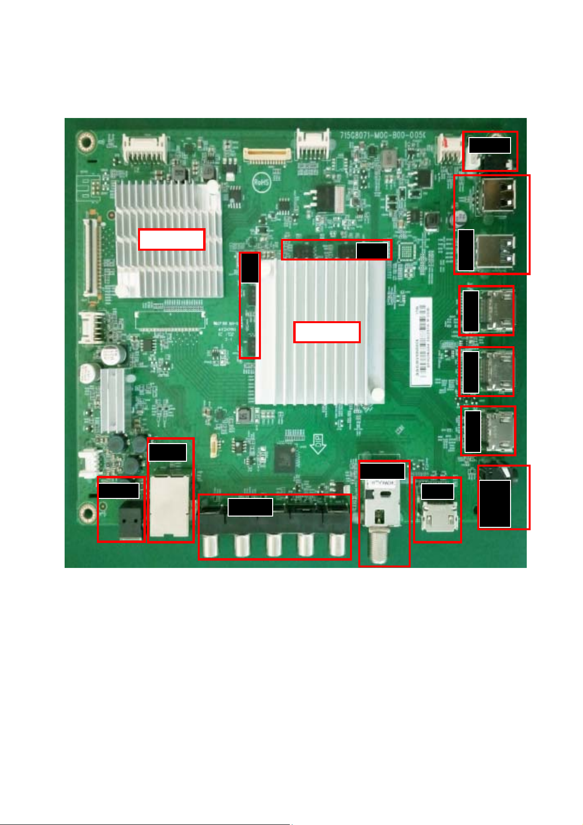
3.1 Cable Dressing
CN9101 CN8601
ECN701
ECN4605
CN4605
MAIN POWER SUPPLY
A
(1054)
ECN417
CN701
CN417
CN401
CN601
B
(1053)
ECN401
KEY BOARD
CONTROL
ECN601
ECN601
ECN401
ECN4605
IR
J
LED
BOARD
1054)
(1184)
Wifi module(Wifi01)
Cable dressing (43" 6102 series)
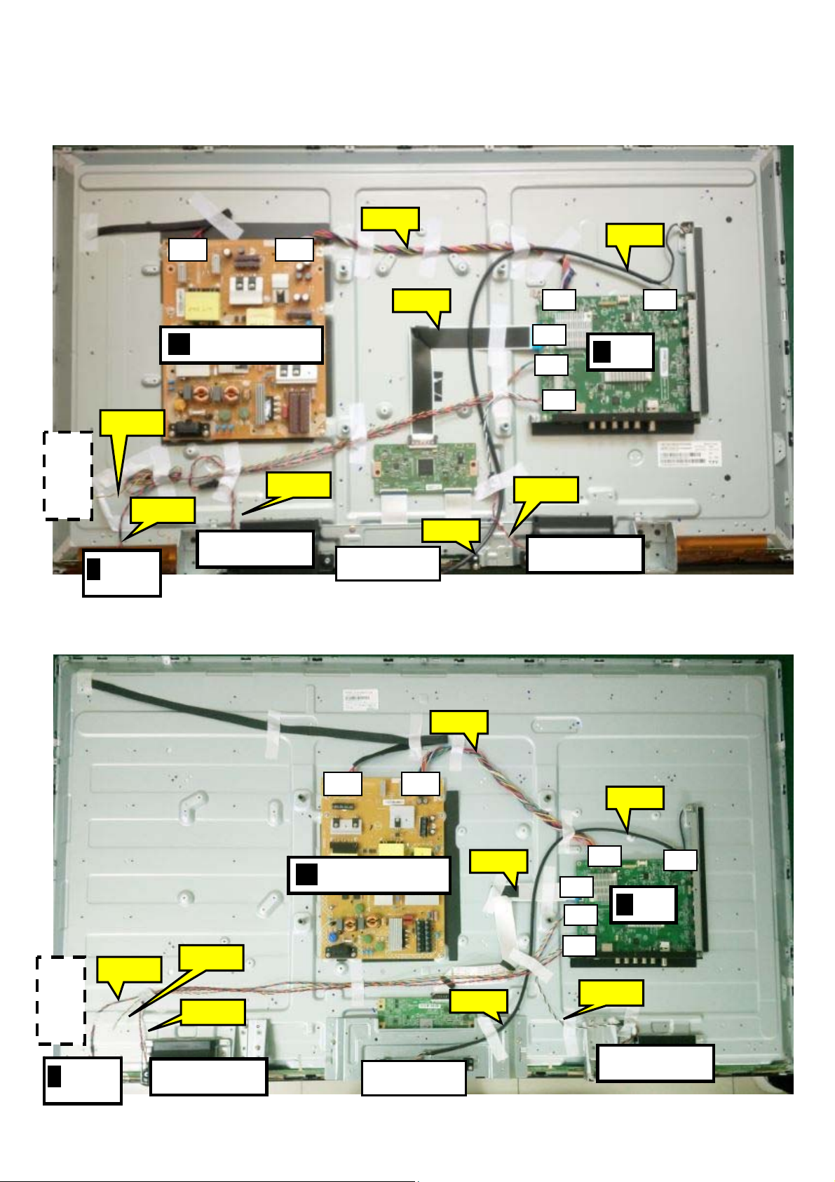
(1184)
KEY BOARD
CONTROL
IR
J
ECN401
LED
BOARD
1054)
ECN401
ECN601
(1184)
ECN701
CN9101CN8601
MAIN POWER SUPPLY
A
(1054)
Wifi module(Wifi01)
Cable dressing (50"/55" 6102 series)
ECN417
ECN4605
CN417
CN401
CN601
ECN4605
CN701
ECN601
(1184)
B
(1053)
CN4605
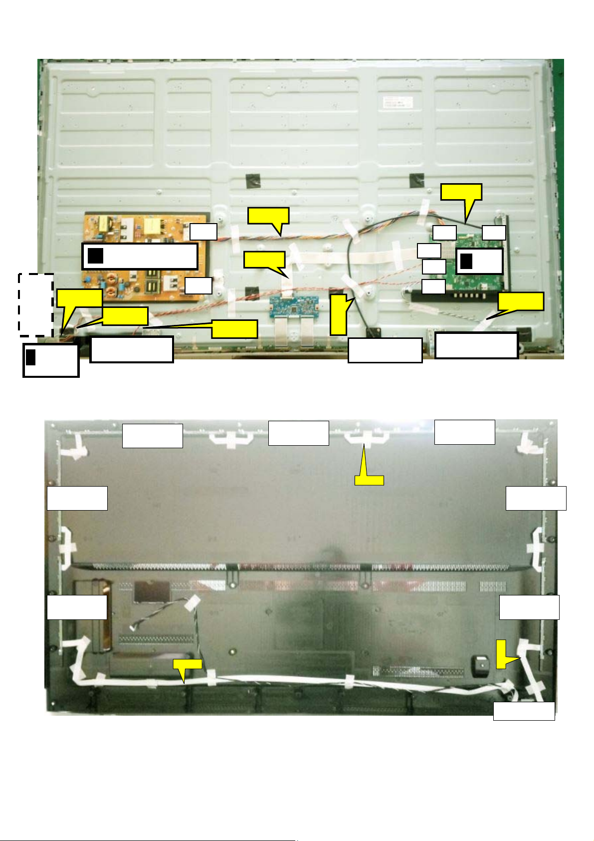
)
LOUDSPEAKER
/
(
LOUDSPEAKER
SSB
CN9102
ECN701
ECN4605
CN701
CN4605
CN417
CN401
CN601
B
(1053)
CONTROL
KEY BOARD
ECN401
MAIN POWER SUPPLY
A
(1054)
CN8601
ECN417
ECN4605
ECN401
ECN601
IR
J
LED
BOARD
1054)
(1184)
Cable dressing (65" 6412 series)
Wifi module(Wifi01)
(1184)
Ambilight (1063)
Ambilight (1061) Ambilight (1061)
Ambilight (1062)
EXA03
Ambilight (1063)
ECN601
Ambilight (1061)
EXA01
Back cover view (65" 6412 series)
Ambilight (1061)
EXA02
Keyboard(1057
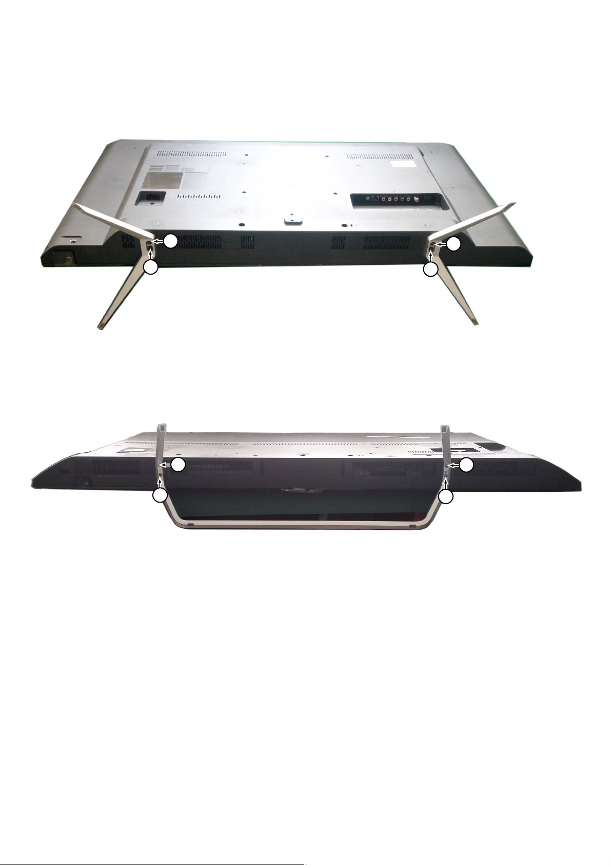
3.2 Assembly/Panel Removal
3.2.1 Stand removal for 6102 serial
1. Remove the fixation screws [1] that secure the stand
2. Take the stand bracket out from the set.
Stand removal for 6412 serial
1. Remove the fixation screws [1] that secure the stand
2. Take the stand bracket out from the set.
1
1
1
1
1
1
1
1
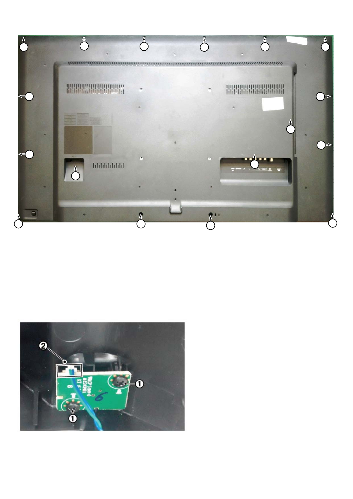
3.2.2 Rear Cover
Warning: Disconnect the mains power cord before removing the rear cover
1. Remove fixation screws [2] and [3] that secure the back cover
2. Gently lift the rear cover from the TV. Make sure that wires and cables are not damaged while lifting the rear cover from the set
2
2
2
3
2
2
2
2 2
2
3
2
3
2
3.2.3 Keyboard Control Unit
1. Remove all the fixation screws from the keyboard control panel [1] and take it out from the Back cover
When defective, replace the whole unit.
2. Release the connector [2] from the SSB Board.
Caution: be careful, the Keyboard is catch on the Back cover, please be careful to avoid damage the fragile connectors!
2
2
2
3.2.4 Small Signal Board (SSB)
Caution: it is mandatory to remount all different screws at their original position during re-assembly. Failure to do so may result in damaging the
SSB.
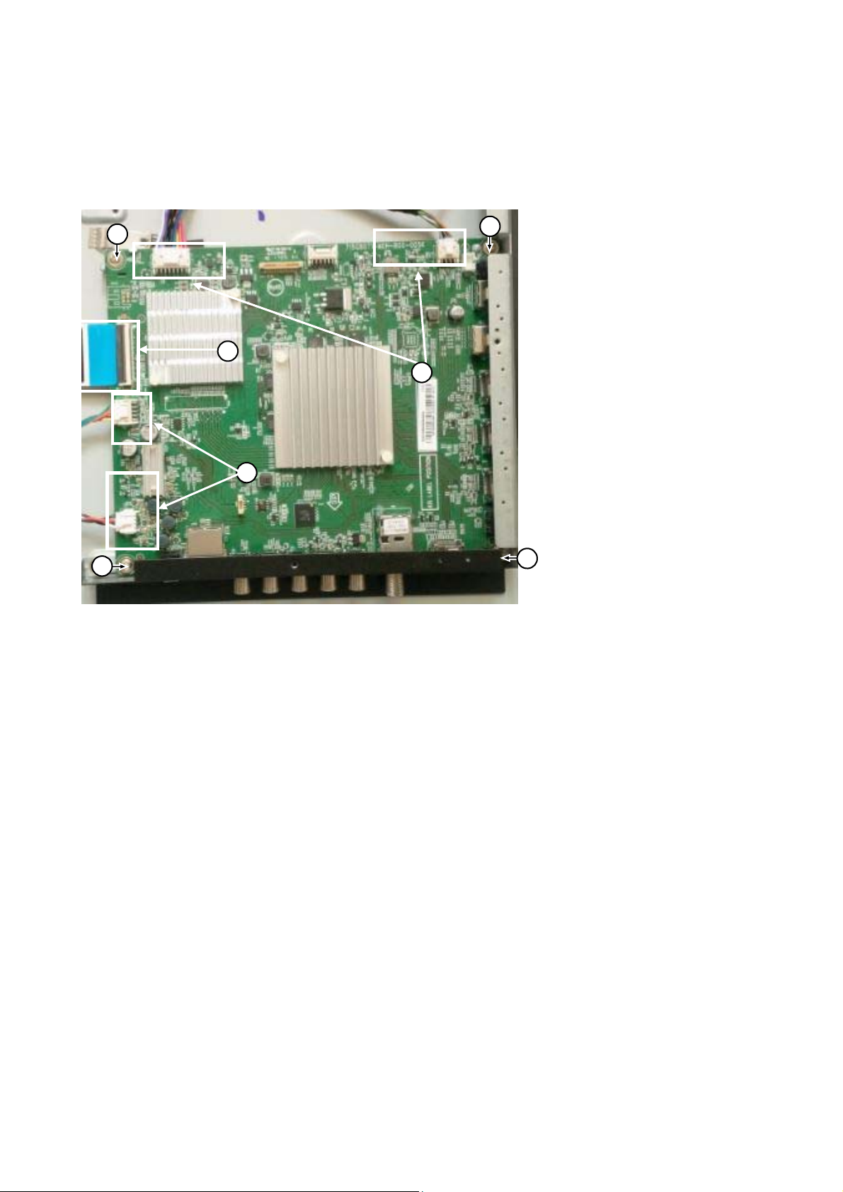
1. Release the clips from the LVDS connector that connect with the SSB[1].
Caution: be careful, as these are very fragile connectors!
1. Unplug all other connectors [2] .
3. Remove all the fixation screws from the SSB [3].
4. The SSB can now be shifted from side connector cover, then lifted and taken out of the I/O bracket.
4. cover, then lifted and taken out of the I/O bracket.
3
3
1
2
2
2
3
3
3.2.5 Power Supply Unit (PSU)
Caution: it is mandatory to remount all different screws at their original position during re-assembly. Failure to do so may result in damaging the
PSU.
1. Gently unplug all connectors from the PSU.
2. Remove all fixation screws from the PSU.
3. The PSU can be taken out of the set now.
3.2.6 IR board Control Unit
1. Unplug the connector from the SSB.
Caution: be careful, as these are very fragile connectors!
3. Remove all the fixation screws [1], [2] and connector [3] from the IR board control unit.
3. Remove the IR lens [4], IR board [5] from the DECO_REAR_COVER.
When defective, replace the whole unit.
3.2.7 Speakers
1. Gently release the tapes that secure the speaker cables.
2. Unplug the speaker connector from the SSB.
3. Take the speakers out.
When defective, replace the both units.

3.2.8 WIFI module
1. Unplug the connector from the SSB..
2. Remove fixation screw that secure the WIFI module,
When defective, replace the whole unit.
3.2.9 LCD Panel
1. Remove the SSB as described earlier.
2. Remove the PSU as described earlier.
3. Remove the keyboard control panel as described earlier.
4. Remove the stand bracket as described earlier.
5. Remove the IR/LED as described earlier.
6. Remove the fixations screws that fix the metal clamps to the front bezel. Take out those clamps.
7. Remove all other metal parts not belonging to the panel.
8. Lift the LCD Panel from the bezel.
When defective, replace the whole unit.

4. Service Modes
4.1 Service Modes
The Service Mode feature is split into following parts:
Service Alignment Mode (SAM).
Factory Mode.
Customer Service Mode (CSM).SAM and the Factory mode offer features, which can be used by the Service engineer to repair/align a TV set.
SAM and the Factory mode offer features, which can be used by the Service engineer to repair/align a TV set. Some features are:
Make alignments (e.g. White Tone), reset the error buffer(SAM and Factory Mode).
Display information (“SAM” indication in upper right corner of screen, error buffer, software version, operating hours,options and option codes,
sub menus).
The CSM is a Service Mode that can be enabled by the consumer. The CSM displays diagnosis information, which the customer can forward to the
dealer or call centre. In CSM mode, “CSM”, is displayed in the top right corner of the screen. The information provided in CSM and the purpose of
CSM is to:
Increase the home repair hit rate.
Decrease the number of nuisance calls.
Solved customers’ problem without home visit.
Note: For the new model range, a new remote control (RC) is used with some renamed buttons. This has an impact on the activation of the Service
modes. For instance the old “MENU” button is now called “HOME” (or is indicated by a “house” icon).
4.2 Service Alignment Mode (SAM)
Purpose
To modify the NVM.
To display/clear the error code buffer.
To perform alignments.
Specifications
Operation hours counter (maximum five digits displayed).
Software version, error codes, and option settings display.
Error buffer clearing.
Option settings.
Software alignments (White Tone).
NVM Editor.
Set screen mode to full screen (all content is visible).
How to Activate SAM
To activate SAM, use one of the following methods:
Press the following key sequence on the remote control transmitter: “062596”, directly followed by the “INFO/OK” button. Do not allow the
display to time out between entries while keying the sequence.
Or via ComPair.
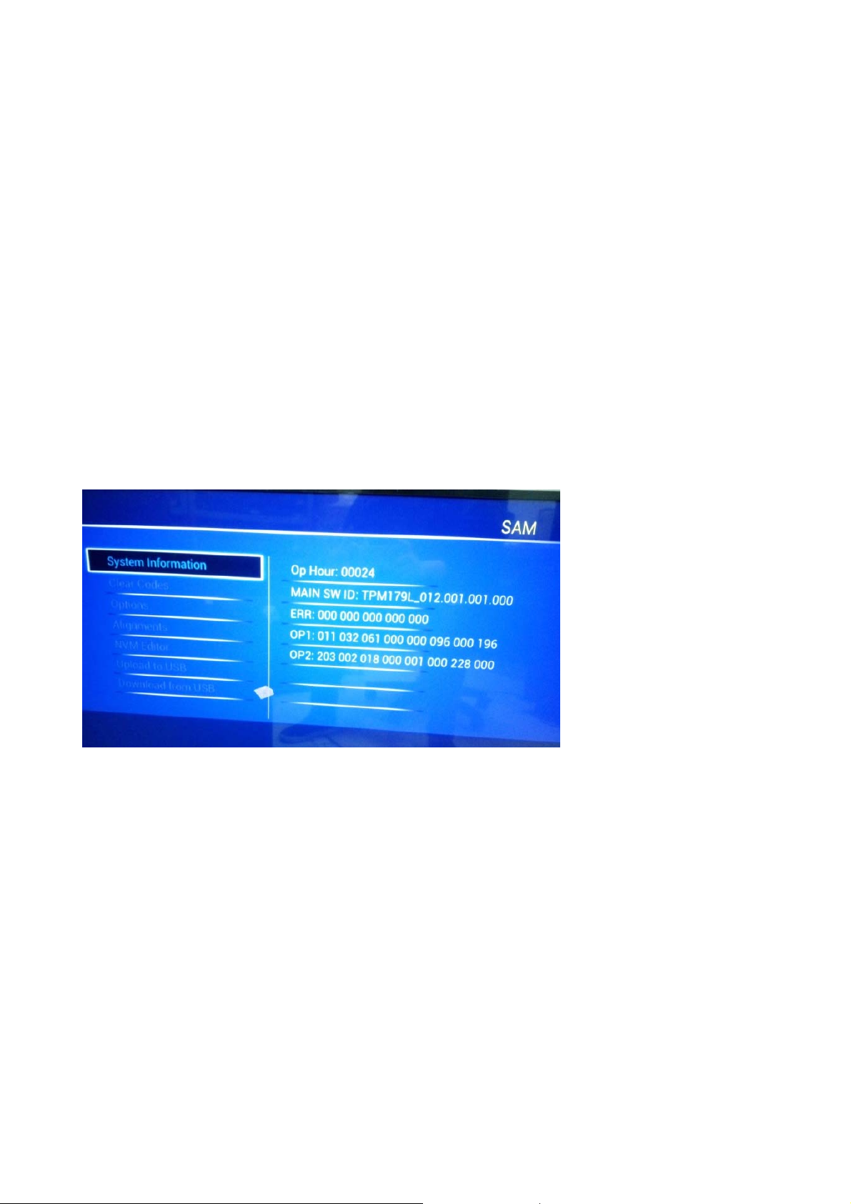
After entering SAM, the following items are displayed,
with “SAM” in the upper right corner of the screen to indicate that the television is in Service Alignment Mode.
How to Navigate
In the SAM menu, select menu items with the UP/DOWN keys on the remote control transmitter. The selected item will be indicated. When not
all menu items fit on the screen, use the UP/DOWN keys to display the next/previous menu items.
With the “LEFT/RIGHT” keys, it is possible to:
– (De) activate the selected menu item.
– (De) activate the selected sub menu.
– Change the value of the selected menu item.
When you press the MENU button once while in top level SAM, the set will switch to the normal user menu (with the SAM mode still active in the
background).
How to Store SAM Settings
To store the settings changed in SAM mode (except the RGB Align settings), leave the top level SAM menu by using the POWER button on the
remote control transmitter or the television set. The mentioned exceptions must be stored separately via the STORE button.
How to Exit SAM
Use one of the following methods:
Switch the set to STANDBY by pressing the mains button on the remote control transmitter or the television set.
Via a standard RC-transmitter, key in “00” sequence.
Note: When the TV is switched “off” by a power interrupt while in SAM, the TV will show up in “normal operation mode” as soon as the power is
supplied again. The error buffer will not be cleared.
SAM mode overview
4.3 Factory mode:
Purpose
To perform extended alignments.
Specifications
Displaying and or changing Panel ID information.
Displaying and or changing Tuner ID information.
Error buffer clearing.
Various software alignment settings.
Testpattern displaying.
Public Broadcasting Service password Reset.
etc.
How to Activate the Factory mode
To activate the Factory mode, use the following method:
Press the following key sequence on the remote control transmitter: from the “menu/home” press “1999”, directly followed by the
“Back/Return” button. Do not allow the display to time out between entries while keying the sequence.

After entering the Factory mode, we can see many items displayed, use the UP/DOWN keys to display the next/previous menu items
Factory mode overview
How to Exit the Factory mode
Use one of the following methods:
Select EXIT_FACTORY from the menu and press the “OK” button.
Note: When the TV is switched “off” by a power interrupt, or normal switch to “stand-by” while in the factory mode, the TV will show up in “normal
operation mode” as soon as the power is supplied again. The error buffer will not be cleared.
4.4 Customer Service Mode (CSM)
Purpose
The Customer Service Mode shows error codes and information on the TVs operation settings.The call centre can instruct the customer (by
telephone) to enter CSM in order to identify the status of the set.This helps the call centre to diagnose problems and failures in the TV set before
making a service call.
The CSM is a read-only mode; therefore, modifications are not possible in this mode.
Specifications
Ignore “Service unfriendly modes”.
Line number for every
line (to make CSM language independent).
Set the screen mode to full
screen (all contents on screen is visible).
After leaving the Customer Service Mode, the original settings are restored.
Possibility to use “CH+” or “CH-” for channel surfing, or enter the specific channel number on the RC.
How to Activate CSM
To activate CSM, press the following key sequence on a standard remote control transmitter: “123654” (do not allow the display to time out
between entries while keying the sequence). After entering the Customer Service Mode, the following items are displayed. use the Right/Left keys
to display the next/previous menu items
Note: Activation of the CSM is only possible if there is no (user) menu on the screen!
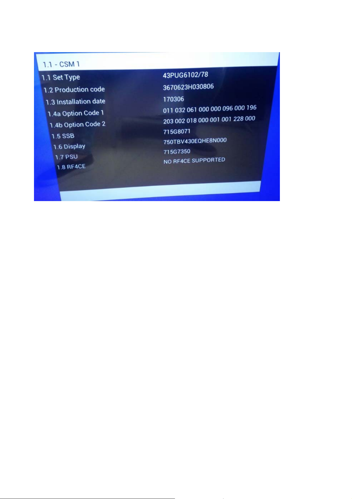
CSM Overview
How to Navigate
By means of the “CURSOR-DOWN/UP” knob (or the scroll wheel) on the RC-transmitter, can be navigated through the menus.
How to Exit CSM
To exit CSM, use one of the following methods.
Press the MENU/HOME button on the remote control transmitter.
Press the POWER button on the remote control transmitter.
Press the POWER button on the television set.
5. Software Upgrading, Error code and Panel Code
5.1 Software Upgrading
5.1.1. The following update is for .pkg file.
1. Rename the file to “upgrade_loader.pkg”
Prepare a USB memory.
2.
3. Copy the software to USB flash disk(root directory).
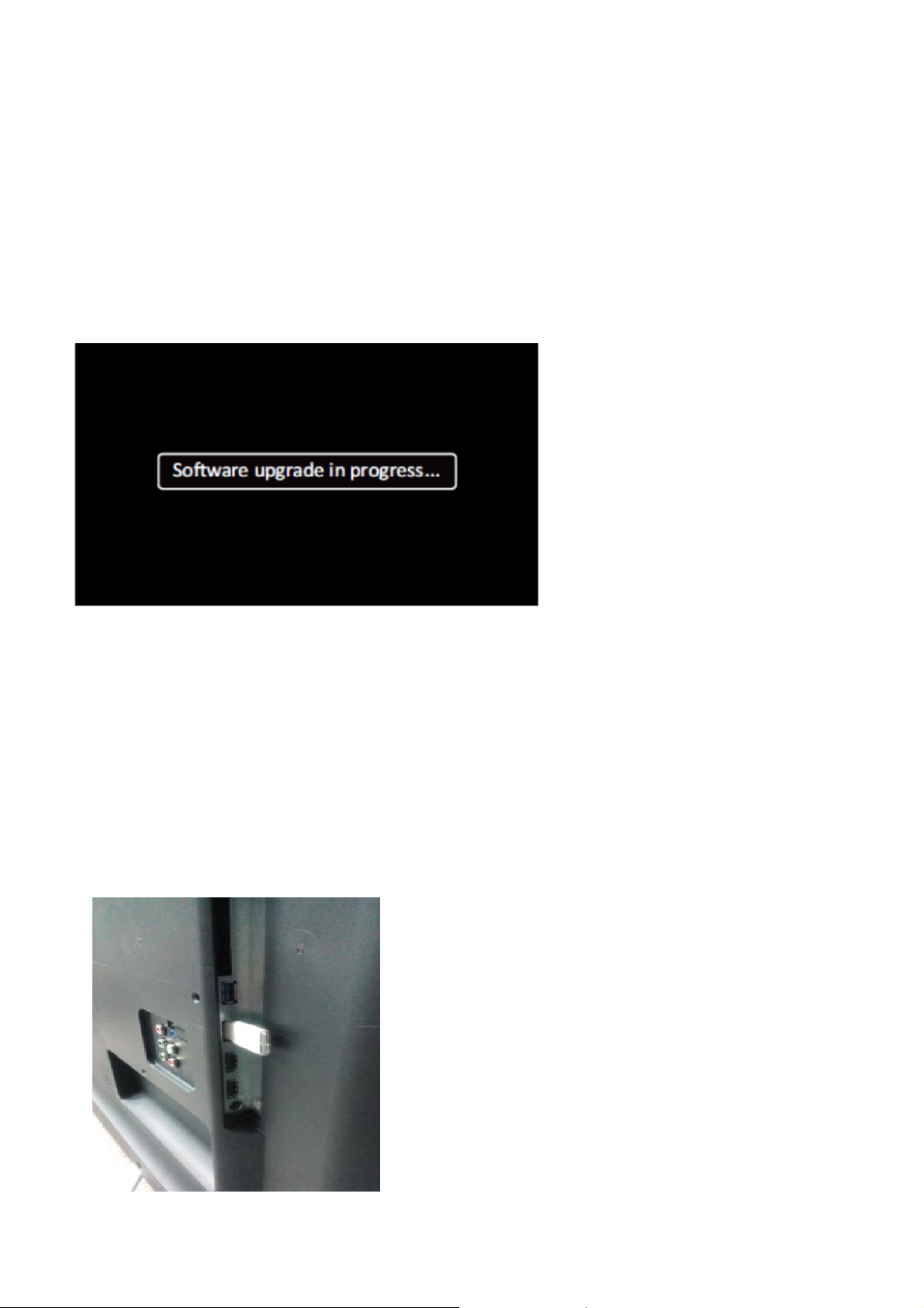
4. Switch off the TV and Insert the USB memory stick that contains the software update files in one of the TV’s USB 2.0 ports.
Note: It contains USB3.0 port, if connect on it, the software may can’t be detected.
5. Switch on the TV. The TV will detect the USB memory s tick automatically. Then a window jumps out as below
6. When the TV software is updated, the TV will turn on again automatically. Remove your USB flash drive.
7. We can enter in CSM or Factory mode to check the current software version.
5.1.2. The following update is for .upg file.
Step 1: Ready for F/W Upgrade
1. Rename the file to “autorun.upg”
2.
Prepare a USB memory.
3. Copy the software to USB flash disk(root directory).
4. Switch on the TV and Insert the USB memory stick that contains the software update files in one of the TV’s USB 2.0 ports
Note the version of this F/W before you change the software file name.
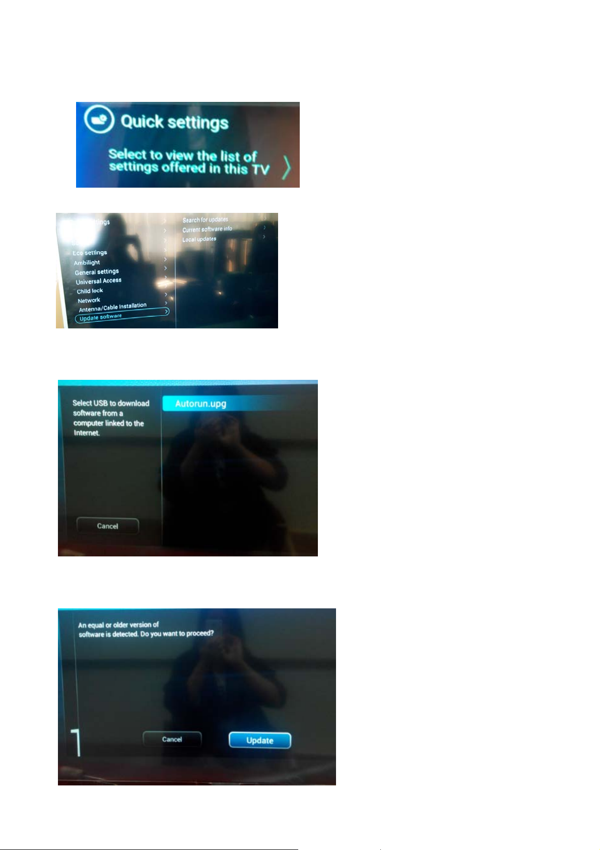
Step 2: F/W Upgrade
1. Press [Quick settings], then Choose [Update Software] in the Settings menu
2.
Choose [Local Updates], then press OK.
3. Select the file that you downloaded and press OK
4. Choose [Update], then choose [Start] on following step
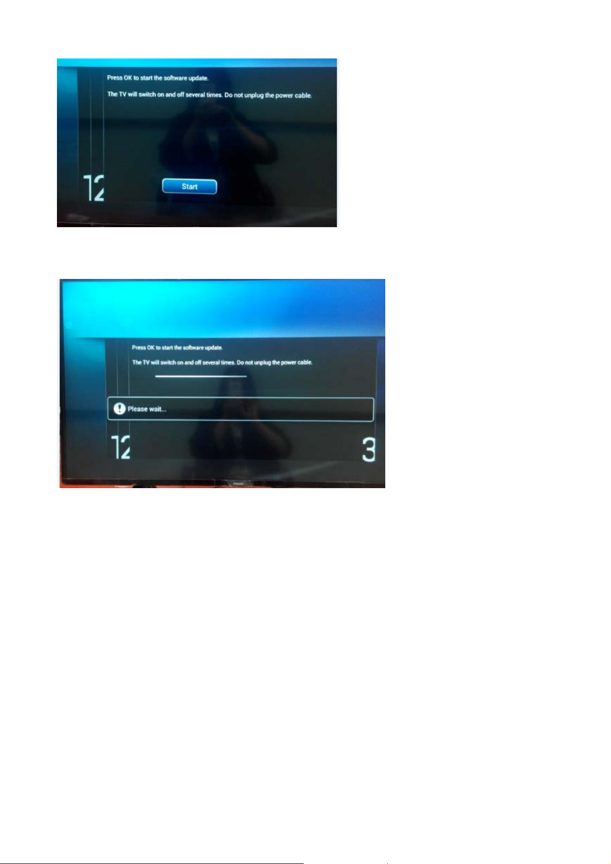
5. Upgrade in progress
Step 3: Check the SW version
1. After burning software, TV will restart
2.
Press “Menu+1999+back”, enter Factory mode to check if the software version is correct
Caution: Please make sure that software upgrade is finished before unplug the USB and AC power!
5.2 Error Code
5.2.1 Introduction
Error codes are required to indicate failures in the TV set. In principle a unique error code is available for every:
• Activated (SW) protection.
• Failing I2C device.
• General I2C error.
The last five errors, stored in the NVM, are shown in the Service menu’s. This is called the error buffer.
The error code buffer contains all errors detected since the last time the buffer was erased. The buffer is written from left to right. When an error occurs that
is not yet in the error code buffer, it is displayed at the left side and all other errors shift one position to the right.
An error will be added to the buffer if this error differs from any error in the buffer. The last found error is displayed on the left.
An error with a designated error code never leads to a deadlock situation. It must always be diagnosable (e.g. error buffer via OSD or blinking LED).
In case a failure identified by an error code automatically results in other error codes (cause and effect), only the error code of the MAIN failure is displayed.
5.2.2 How to Read the Error Buffer
You can read the error buffer in three ways:
• On screen via the SAM/CSM (if you have a picture).
Example:
– ERROR: 000 000 000 000 000: No errors detected
– ERROR: 013 000 000 000 000: Error code 13 is the last and only detected error
– ERROR: 034 013 000 000 000: Error code 13 was detected first and error code 34 is the last detected (newest) error
• Via the blinking LED procedure (when you have no picture).
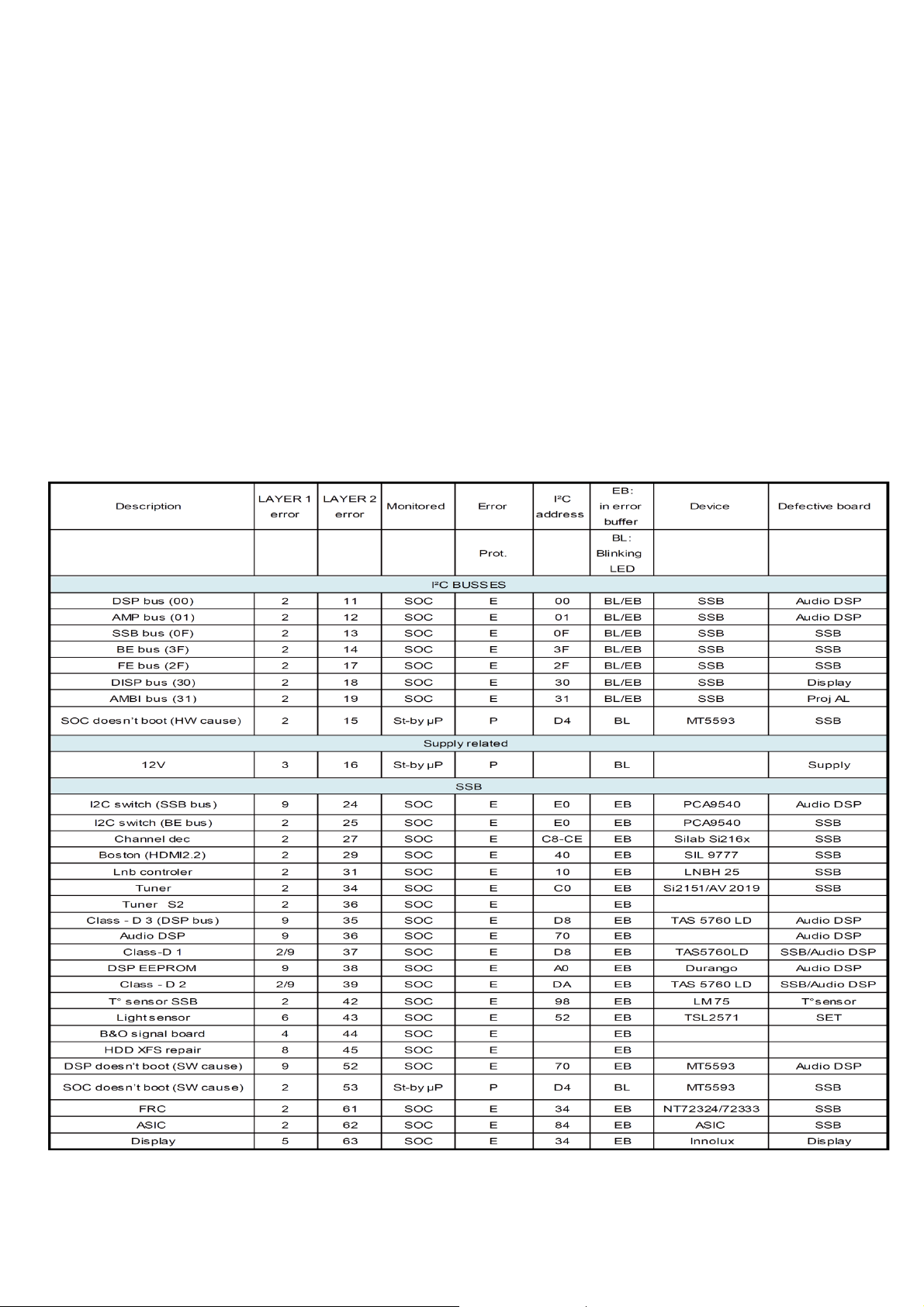
5.2.3 Error codes overview
In this chassis only “layer 2” error codes are available and point to problems on the SSB. They are triggered by LED blinking
when CSM is activated. Only the following layer 2 errors are defined:
5.2.4 How to Clear the Error Buffer
The error code buffer is cleared in the following cases:
• By using the CLEAR command in the SAM menu
• By using the CLEAR command in the Factory mode:
• By using the following key sequence on the remote control transmitter: “062599” directly followed by the OK button.
• If the contents of the error buffer have not changed for 50 hours, the error buffer resets automatically.
Note: If you exit SAM by disconnecting the mains from the television set, the error buffer is not reset.
5.3 Panel Code
Press the following key sequence on a standard RC transmitter: “062598” directly followed by MENU and “xxx”, where “xxx” is a 3 digit decimal value
of the panel type: see column “Display Code” in below tab. After resetting the Display Code, restart the set immediately.
CTN_ALT BOM# Panel Type
43PUG6102/77 TPT430U3-EQYSHM.G S1AE
43PUG6102/78 TPT430U3-EQYSHM.G S1AE
50PUG6102/77 TPT500U1-EQYSKM.G S1A
50PUG6102/77 TPT500B5-GT011H S011A
50PUG6102/78 TPT500U1-EQYSKM.G S1A
50PUG6102/78 TPT500B5-GT011H S011A
55PUG6102/77 TPT490F2-FHBN0.K S8940R XM
55PUG6102/78 TPT550U2-EQYSKM.G S5K
55PUG6102/78 TPT550J1-QUBN0.K S8940Q
65PUG6412/77 TPT650UA-QVN06.U S300A
g
6. Circuit Descriptions
6.1 Introduction
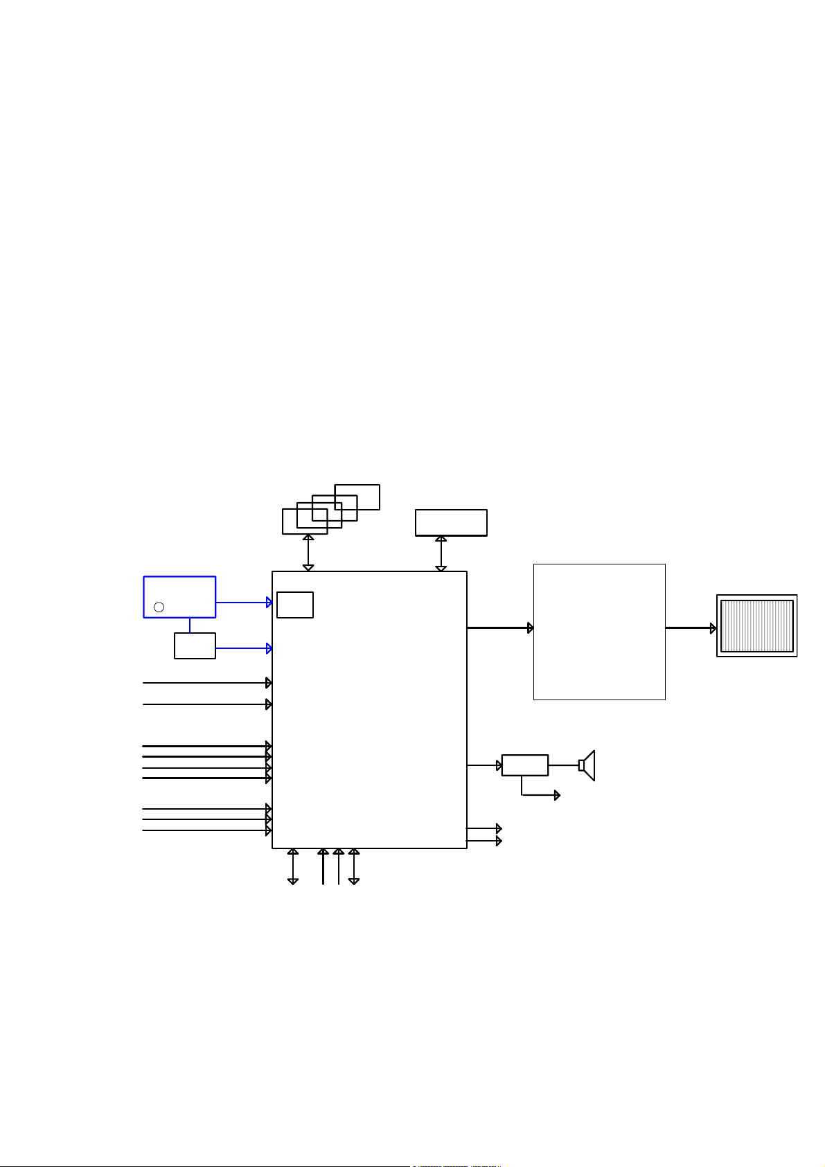
The TPM17.9L LA is a new chassis launched in LATAM in 2017. The whole range is covered by MT5596LGEJ HSFBGA-757 platform. The major deltas
versus its predecessor support NTSC;PAL-M; PAL-N AND ISDB-T with also multi-media, CEC,ARC, SPDIF functionality.
The TPM17.9L LA chassis comes with the following stylings:
series xxPHG6102/xx
series xxPHG6412/xx
6.1.1 Implementation
Key components of this chassis are:
SCALER MT5596LGEJ HSFBGA-757
SCALER MST7484GC BGA-420
EMMC THGBMDG5D1LBAIT 4GB FBGA153
AUDIO AD87588-LG48NAY 20W E-LQFP-48
TUNER Latam TDSY-H480F
6.1.2 Block diagram
Block Diagram
TDSY H480F
DVB- T 2
DEMOD
Si2168
YPbPr+L/R
RJ45
HDMI1
HDMI2
HDMI3
HDMI4
USB 3.0
USB 2.0
USB
WiFi
ATV
SPI for Scanning
backli
ht
DDR3
MT5596L
RC
KEY
UART
EMMC 4GB
HD& FHD LCD PANEL
VB1
AUD IO AMP
I2S
AD87588
ARC
SPDIF
MST7484
3W/5 W/10W SPK
Headphone
VB1
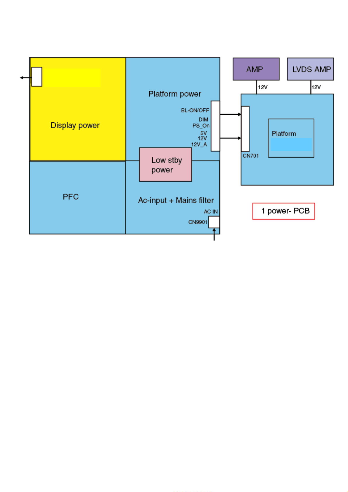
6.2 Power Supply
Power architecture of this platform.
CN8601
MT5596LGE
6.2.1 Power Supply Unit
All power supplies are a black box for Service. When defective, a new board must be ordered and the defective one must be returned, unless the main fuse
of the board is broken. Always replace a defective fuse with one with the correct specifications! This part is available in the regular market.
Consult the Philips Service web portal for the order codes of the boards.
Important delta’s with the platform are:
• New power architecture for LED backlight
• “Boost”-signal is now a PWM-signal + continuous variable
The control signals are:
• PS-ON
• Lamp “on/off”
• DIM (PWM) (not for PSDL)
In this manual, no detailed information is available because of design protection issues.
• +8.5V output (standby mode)
• +12 output (on-mode)
• +12V_audio (audio AMP power)
• Output to the display; in case of
- IPB: High voltage to the LCD panel
- PSL and PSLS (LED-driver outputs)
- PSDL (high frequent) AC-current.
6.2.2 Diversity
The diversity in power supply units is mainly determined by the diversity in displays.
The following displays can be distinguished:
• CCFL/EEFL backlight: power panel is conventional IPB
 Loading...