


Professional
Display Solutions
Q Line
43BDL3550Q/50BDL3550Q
55BDL3550Q
User Manual (English)
www.philips.com/welcome

43BDL3550Q_50BDL3550Q_55BDL3550Q
Safety Instructions
Safety precautions and maintenance
WARNING: Use of controls, adjustments or procedures other than those specied in this documentation may
result in exposure to shock, electrical hazards and/or mechanical hazards.
Read and follow these instructions when connecting and using your display:
Operation:
• Keep the display out of direct sunlight and away from stoves or any other heat sources.
• Keep the display away from oil, otherwise the plastic cover may be damaged.
• It is recommended to set the display up in the well-ventilated place.
• Ultra-violet ray lter is necessary of outdoor operation.
• If the product will be used in extreme conditions such as high temperature, humidity, display patterns or operation time
etc... It is strongly recommended to contact Philips for Application engineering advice. Otherwise, its reliability and function
may not be guaranteed. Extreme conditions are commonly found at Airports, Transit Stations, Banks, Stock market, and
Controlling systems.
• Remove any object that could fall into ventilation holes or prevent proper cooling of the display’s electronics.
• Do not block the ventilation holes on the cabinet.
• When positioning the display, make sure the power plug and outlet are easily accessible.
• When turning o the display by detaching the power cord, wait 6 seconds before re-attaching the power cord for normal
operation.
• Ensure the use of an approved power cord provided by Philips at all times. If your power cord is missing, please contact your
local service center.
• Do not subject the display to severe vibration or high impact conditions during operation.
• Do not knock or drop the display during operation or transportation.
• The eye bolt is for usage in short-time maintenance and installation. We suggest not to use the eye bolt for more than 1 hour.
Prolong usage is prohibited. Please keep a clear safety area under the display while using the eye bolt.
Maintenance:
• To protect your display from possible damage, do not put excessive pressure on the LCD panel. When moving your display,
grasp the frame to lift; do not lift the display by placing your hand or ngers on the LCD panel.
• Unplug the display if you are not going to use it for an extensive period of time.
• Unplug the display if you need to clean it with a slightly damp cloth. The screen may be wiped with a dry cloth when the
power is o. However, never use organic solvent, such as, alcohol, or ammonia-based liquids to clean your display.
• To avoid the risk of shock or permanent damage to the set, do not expose the display to dust, rain, water or an excessively
moist environment.
• If your display becomes wet, wipe it with dry cloth as soon as possible.
• If a foreign substance or water gets in your display, turn the power o immediately and disconnect the power cord. Then
remove the foreign substance or water, and send the unit to the maintenance center.
• Do not store or use the display in locations exposed to heat, direct sunlight or extreme cold.
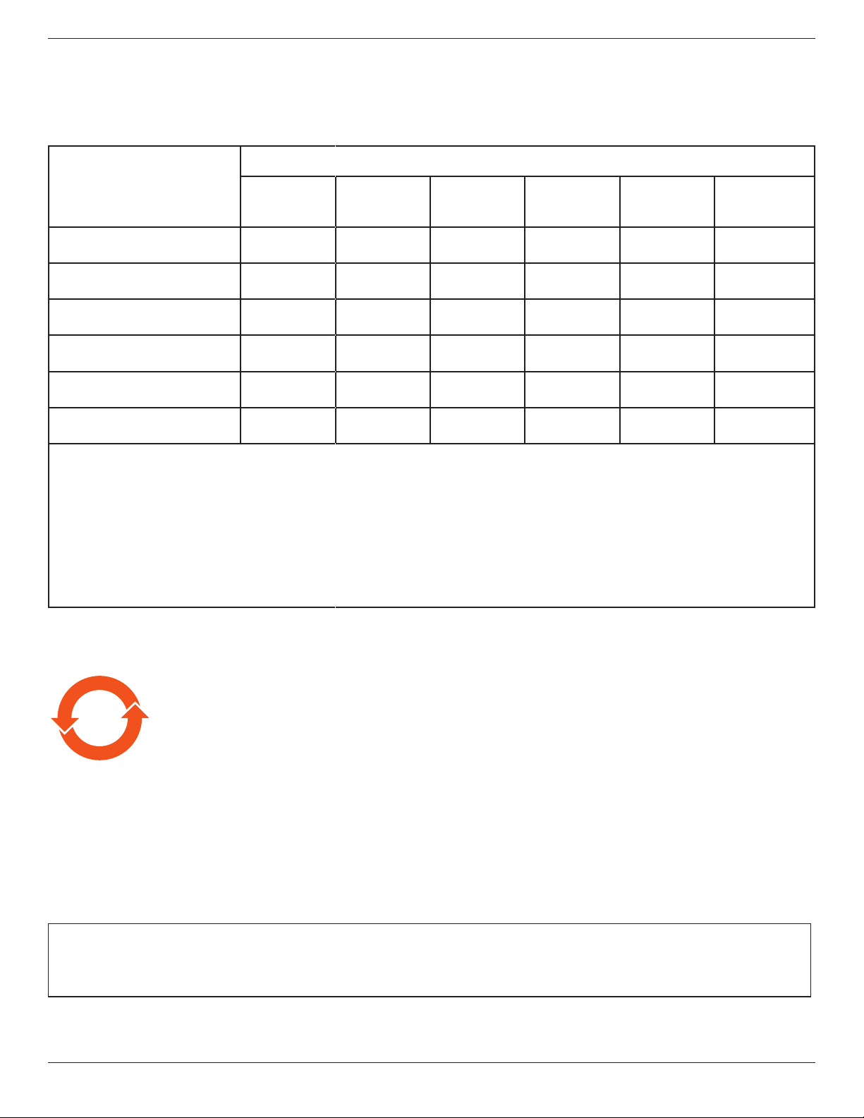
• In order to maintain the best performance of your display and ensure a longer lifetime, we strongly recommend using the
display in a location that falls within the following temperature and humidity ranges.
Environmental absolute ratings
Item Min. Max. Unit
Storage temperature -20 65 °C
Operation temperature 0 40 °C
Glass Suraface temperature
(Operation)
Storage humidity 5 90 % RH
Operating humidity 20 80 % RH
0 65 °C
• LCD panel temperature need to be 25 degrees Celsius at all time for better luminance performance.
ii
43BDL3550Q_50BDL3550Q_55BDL3550Q
• Only the lifetime of the display stated in this specication is guaranteed if the display is used under the proper operation
conditions.
IMPORTANT: Always activate a moving screen saver program when you leave your display unattended. Always activate a
periodic screen refresh application if the unit will display unchanging static content. Uninterrupted display of still or static
images over an extended period may cause “burn in”, also known as “after-imaging” or “ghost imaging”, on your screen. This is
a well-known phenomenon in LCD panel technology. In most cases, the “burned in” or “after-imaging” or “ghost imaging” will
disappear gradually over a period of time after the power has been switched o.
WARNING: Severe “burn-in” or “after-image” or “ghost image” symptoms will not disappear and cannot be repaired. This is also
not covered under the terms of your warranty.
Service:
• The casing cover should be opened only by qualied service personnel.
• If there is any need for repair or integration, please contact your local service center.
• Do not leave your display under direct sunlight.
If your display does not operate normally, having followed the instructions set out in this document, please
contact a technician or your local service center.
Stability Hazard.
The device may fall, causing serious personal injury or death. To prevent injury, this device must be securely attached to the
oor/wall in accordance with the installation instructions.
Read and follow these instructions when connecting and using your display:
• Unplug the display if you are not going to use it for an extensive period of time.
• Unplug the display if you need to clean it with a slightly damp cloth. The screen many be wiped with a dry
cloth when the power is o. However, never use alcohol, solvents or ammonia-based liquids.
• Consult a service technician if the display does not operate normally when you have followed the instructions
in this manual.
• The casing cover should be opened only by qualied service personnel.
• Keep the display out of direct sunlight and away from stoves or any other heat sources.
• Remove any object that could fall into the vents or prevent proper cooling of the display’s electronics.
• Do not block the ventilation holes on the cabinet.
• Keep the display dry. To avoid electric shock, do not expose it to rain or excessive moisture.
• When turning o the display by detaching the power cable or DC power cord, wait for 6 seconds before reattaching the power cable or DC power cord for normal operation..
• To avoid the risk of shock or permanent damage to the set do not expose the display to rain or excessive
moisture.
• When positioning the display, make sure the power plug and outlet are easily accessible.
• IMPORTANT: Always activate a screen saver program during your application. If a still image in high contrast
remains on the screen for an extended period of time, it may leave an ‘after-image’ or ‘ghost image’ on the
front of the screen. This is a well-known phenomenon that is caused by the shortcomings inherent in LCD
technology. In most cases the afterimage will disappear gradually over a period of time after the power has
been switched o. Be aware that the after-image symptom cannot be repaired and is not covered under
warranty.
• If provided with a 3-pin attachment plug on the power cord, plug the cord into a grounded (earthed) 3-pin
outlet. Do not disable the power cord grounding pin, for example, by attaching a 2-pin adapter. The grounding
pin is an important safety feature.
EU Declaration of Conformity
This device complies with the requirements set out in the Council Directive on the Approximation of the Laws of the Member
States relating to Electromagnetic Compatibility (2014/30/EU), Low-voltage Directive (2014/35/EU), RoHS directive (2011/65/
EU).
This product has been tested and found to comply with the harmonized standards for Information Technology Equipment, these
harmonized standards published under Directives of Ocial Journal of the European Union.
ESD Warnings
When user close to the monitor may cause the equipment discharge and reboot to the display of main menu while USB media is
playing.
iii
43BDL3550Q_50BDL3550Q_55BDL3550Q
Warning:
This equipment is compliant with Class A of EN55032/CISPR 32. In a residential environment this equipment may cause radio
interference.
Federal Communications Commission (FCC) Notice (U.S. Only)
NOTE: This equipment has been tested and found to comply with the limits for a Class A digital device,
pursuant to part 15 of the FCC Rules. These limits are designed to provide reasonable protection against harmful
interference when the equipment is operated in a commercial environment. This equipment generates, uses, and
can radiate radio frequency energy and, if not installed and used in accordance with the instruction manual, may
cause harmful interference to radio communications. Operation of this equipment in a residential area is likely to
cause harmful interference in which case the user will be required to correct the interference at his own expense.
Changes or modications not expressly approved by the party responsible for compliance could void the user’s
authority to operate the equipment.
Use only an RF shielded cable that was supplied with the display when connecting this display to a computer device.
To prevent damage which may result in re or shock hazard, do not expose this appliance to rain or excessive moisture.
This device complies with Part 15 of the FCC Rules. Operation is subject to the following two conditions: (1) This device may not
cause harmful interference, and (2) this device must accept any interference received, including interference that may cause
undesired operation.
Envision Peripherals Inc.
490 N McCarthy Blvd, Suite #120
Milpitas, CA 95035
USA
iv
43BDL3550Q_50BDL3550Q_55BDL3550Q
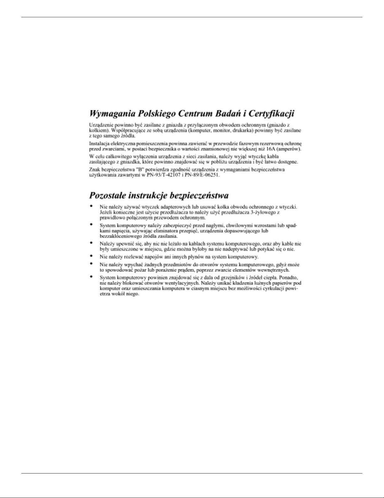
Polish Center for Testing and Certication Notice
The equipment should draw power from a socket with an attached protection circuit (a three-prong socket). All equipment that
works together (computer, display, printer, and so on) should have the same power supply source.
The phasing conductor of the room’s electrical installation should have a reserve short-circuit protection device in the form of a
fuse with a nominal value no larger than 16 amperes (A).
To completely switch o the equipment, the power supply cable must be removed from the power supply socket, which should
be located near the equipment and easily accessible.
A protection mark “B” conrms that the equipment is in compliance with the protection usage requirements of standards PN93/T-42107 and PN-89/E-06251.
Electric, Magnetic and Electromagnetic Fields (“EMF”)
1. We manufacture and sell many products targeted at consumers, which, like any electronic apparatus, in general have the
ability to emit and receive electromagnetic signals.
2. One of our leading Business Principles is to take all necessary health and safety measures for our products, to comply with
all applicable legal requirements and to stay well within the EMF standards applicable at the time of producing the products.
3. We are committed to develop, produce and market products that cause no adverse health eects.
4. We conrm that if its products are handled properly for their intended use, they are safe to use according to scientic
evidence available today.
5. We play an active role in the development of international EMF and safety standards, enabling us to anticipate further
developments in standardization for early integration in its products.
v
43BDL3550Q_50BDL3550Q_55BDL3550Q
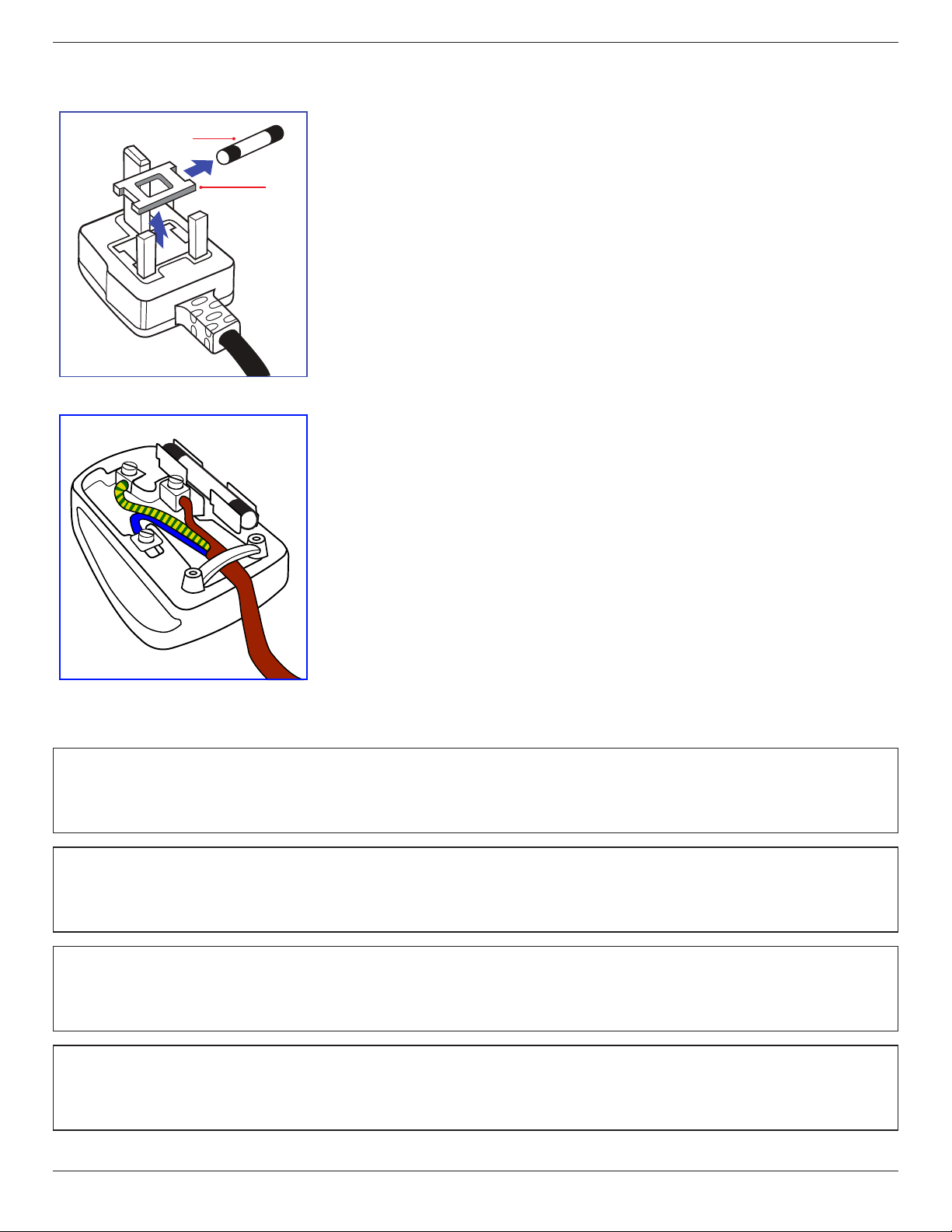
Information for U.K. only
(B)
(A)
WARNING - THIS APPLIANCE MUST BE EARTHED.
Important:
This apparatus is supplied with an approved moulded 13A plug. To change a fuse in
this type of plug proceed as follows:+
1. Remove fuse cover and fuse.
2. Fit new fuse which should be a BS 1362 5A,A.S.T.A. or BSI approved type.
3. Ret the fuse cover.
If the tted plug is not suitable for your socket outlets, it should be cut o and an
appropriate 3-pin plug tted in its place.
If the mains plug contains a fuse, this should have a value of 5A. If a plug without a
fuse is used, the fuse at the distribution board should not be greater than 5A.
NOTE: The severed plug must be destroyed to avoid a possible shock hazard should
it be inserted into a 13A socket elsewhere.
How to connect a plug
The wires in the mains lead are coloured in accordance with the following code:
BLUE - “NEUTRAL” (“N”)
BROWN - “LIVE” (“L”)
GREEN & YELLOW - “EARTH” (“E”)
1. The GREEN & YELLOW wire must be connected to the terminal in the plug which is
marked with the letter “E” or by the Earth symbol or coloured GREEN or GREEN &
YELLOW.
2. The BLUE wire must be connected to the terminal which is marked with the letter
“N” or coloured BLACK.
3. The BROWN wire must be connected to the terminal which marked with the letter
“L” or coloured RED.
Before replacing the plug cover, make certain that the cord grip is clamped over the
sheath of the lead - not simply over the three wires.
North Europe (Nordic Countries) Information
Placering/Ventilation
VARNING:
FÖRSÄKRA DIG OM ATT HUVUDBRYTARE OCH UTTAG ÄR LÄTÅTKOMLIGA, NÄR DU STÄLLER DIN UTRUSTNING PÅPLATS.
Placering/Ventilation
ADVARSEL:
SØRG VED PLACERINGEN FOR, AT NETLEDNINGENS STIK OG STIKKONTAKT ER NEMT TILGÆNGELIGE.
Paikka/Ilmankierto
VAROITUS:
SIJOITA LAITE SITEN, ETTÄ VERKKOJOHTO VOIDAAN TARVITTAESSA HELPOSTI IRROTTAA PISTORASIASTA.
Plassering/Ventilasjon
ADVARSEL:
NÅR DETTE UTSTYRET PLASSERES, MÅ DU PASSE PÅ AT KONTAKTENE FOR STØMTILFØRSEL ER LETTE Å NÅ.
vi
43BDL3550Q_50BDL3550Q_55BDL3550Q
China RoHS
根据中国大陆《电器电子产品有害物质限制使用管理办法》,以下部分列出了本产品中可能包含的有害
物质的名称和含量。
有害物质
部件名称
外壳 O O O O O O
液晶显示屏 X O O O O O
电路板组件* X O O O O O
电源适配器 X O O O O O
电源线/连接线 X O O O O O
遥控器 X O O O O O
本表格依据SJ/T 11364 的规定编制。
*: 电路板组件包括印刷电路板及其构成的零部件,如电阻、电容、集成电路、连接器等。
O: 表示该有害物质在该部件所有均质材料中的含量均在 GB/T 26572规定的限量要求以下。
X: 表示该有害物质至少在该部件的某一均质材料中的含量超出GB/T 26572规定的限量要求。
上 表 中 打“ X”的部件,应功能需要,部分有害物质含量超出GB/T 26572规 定 的 限 量 要 求 ,但 符 合 欧 盟
RoHS法规要求(属于豁免部分)。
铅
(Pb)
汞
(Hg)
镉
(Cd)
六价铬
(Cr (VI))
多溴联苯
(PBB)
多溴二苯醚
(PBDE)
备注:上表仅做为范例,实际标示时应依照各产品的实际部件及所含有害物质进行标示。
10
环保使用期限
此标识指期限 ( 十年 ),电子电气产品中含有的有害物质在正常使用的条件下不会发生外泄或突变,电
子电气产品用户使用该电子电气产品不会对环境造成严重污染或对其人身、财产造成严重损害的期限。
《废弃电器电子产品回收处理管理条例》提示性说明
为了更好地关爱及保护地球,当用户不再需要此产品或产品寿命终止时,请遵守国家废弃电器电子产品
回收处理相关法律法规,将其交给当地具有国家认可的回收处理资质的厂商进行回收处理,不当利用或
者处置可能会对环境和人类健康造成影响。
警告
此为 A 级产品。在生活环境中,该产品可能会造成无线电干扰。在这种情况下,可能需要用户对
干扰采取切实可行的措施。
vii
43BDL3550Q_50BDL3550Q_55BDL3550Q
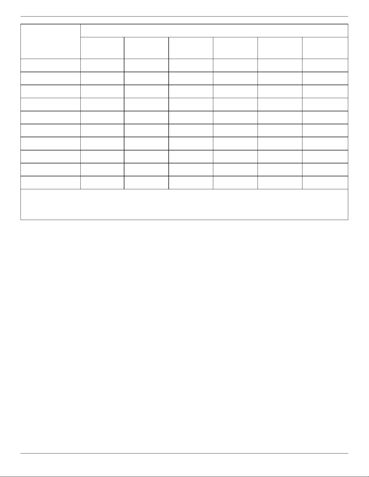
限用物質及其化學符號
單元
鉛
(Pb)
汞
(Hg)
鎘
(Cd)
六價鉻
(Cr+6)
多溴聯苯
(PBB)
多溴二苯醚
(PBDE)
塑料外框 ○ ○ ○ ○ ○ ○
後殼 ○ ○ ○ ○ ○ ○
液晶面板 - ○ ○ ○ ○ ○
電路板組件 - ○ ○ ○ ○ ○
底座 ○ ○ ○ ○ ○ ○
電源線 - ○ ○ ○ ○ ○
其他線材 - ○ ○ ○ ○ ○
遙控器 - ○ ○ ○ ○ ○
喇叭(選配) - ○ ○ ○ ○ ○
風扇(選配) - ○ ○ ○ ○ ○
備考1.〝○〞係指該項限用物質之百分比含量未超出百分比含量基準值。
備考2.〝-〞係指該項限用物質為排除項目。
警語 : 使用過度恐傷害視力。
注意事項 :
(1) 使用30分鐘請休息10分鐘。
(2) 未滿2歲幼兒不看螢幕,2歲以上每天看螢幕不要超過1小時。
警告使用者 :
此為甲類資訊技術設備 , 於居住環境中使用時 , 可能會造成射頻擾動 , 在此種情況下 , 使用者會被
要求採取某些適當的對策。
Turkey RoHS:
Türkiye Cumhuriyeti: EEE Yönetmeliğine Uygundur
Ukraine RoHS:
Обладнання відповідає вимогам Технічного регламенту щодо обмеження використання деяких небезпечних речовин в
електричному та електронному обладнанні, затвердженого постановою Кабінету Міністрів України від 3 грудня 2008 № 1057
End-of-Life Disposal
Your new Public Information Display contains materials that can be recycled and reused. Specialized companies can recycle
your product to increase the amount of reusable materials and to minimize the amount to be disposed of.
Please nd out about the local regulations on how to dispose of your old display from your local Philips dealer.
(For customers in Canada and U.S.A.)
This product may contain lead and/or mercury. Dispose of in accordance to local-state and federal regulations. For additional
information on recycling contact www.eia.org (Consumer Education Initiative)
viii
43BDL3550Q_50BDL3550Q_55BDL3550Q
Waste Electrical and Electronic Equipment-WEEE
Attention users in European Union private households
This marking on the product or on its packaging illustrates that, under European Directive 2012/19/EU governing
used electrical and electronic appliances, this product may not be disposed of with normal household waste. You
are responsible for disposal of this equipment through a designated waste electrical and electronic equipment
collection. To determine the locations for dropping o such waste electrical and electronic, contact your local
government oce, the waste disposal organization that serves your household or the store at which you purchased
the product.
Attention users in United States:
Please dispose of according to all Local, State and Federal Laws. For the disposal or recycling information, contact: www.
mygreenelectronics.com or
www.eiae.org.
End of Life Directives-Recycling
Your new Public Information Display contains several materials that can be recycled for new users.
Please dispose of according to all Local, State, and Federal laws.
50BDL3550Q/55BDL3550Q
ENERGY STAR is a program run by the U.S. Environmental Protection Agency (EPA) and U.S. Department of Energy
(DOE) that promotes energy eciency.
This product qualies for ENERGY STAR in the “factory default” settings and this is the setting in which power
savings will be achieved.
Changing the factory default picture settings or enabling other features will increase power consumption that
could exceed the limits necessary to qualify for ENERGY STAR rating.
For more information on the ENERGY STAR program, refer to energystar.gov.
Restriction on Hazardous Substances statement (India)
This product complies with the “E-Waste (Management) Rules, 2016” CHAPTER V, rule 16, sub-rule (1) . Whereas New Electrical
and Electronic Equipment and their components or consumables or parts or spares do not contain Lead, Mercury, Cadmium,
Hexavalent Chromium, polybrominated biphenyls and polybrominated diphenyl ethers beyond a maximum concentration
value of 0.1% by weight in homogenous materials for lead, mercury, hexavalent chromium, polybrominated biphenyls and
polybrominated diphenyl ethers and of 0.01% by weight in homogenous materials for cadmium. except of exemptions set in
Schedule 2 of the Rule.
E-Waste Declaration for India
This symbol on the product or on its packaging indicates that this product must not be disposed of with
your other household waste. Instead it is your responsibility to dispose of your waste equipment by handing
it over to a designated collection point for the recycling of waste electrical and electronic equipment . The
separate collection and recycling of your waste equipment at the time of disposal will help to conserve natural
resources and ensure that it is recycled in a manner that protects human health and the environment. For more
information about E -waste please visit http://www.india.philips.com/about/sustainability/recycling/index.
page and to know where you can drop o your waste equipment for recycling in India please contact on below
given contact details.
Helpline number: 1800-425-6396 (Monday to Saturday, 9 a.m. to 5:30 pm)
E-mail: india.callcentre@tpv-tech.com
ix
43BDL3550Q_50BDL3550Q_55BDL3550Q
Após o uso, as pilhas
deverão ser entregues ao
estabelecimento comercial
ou
e/ou baterias
rede de assistência técnica
autorizada.
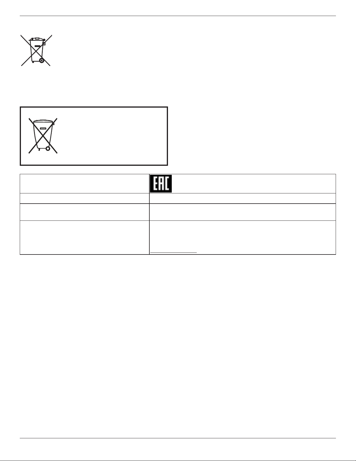
Batteries
For EU: The crossed-out wheeled bin implies that used batteries should not be put to the general household
waste! There is a separate collection system for used batteries, to allow proper treatment and recycling in
accordance with legislation.
Please contact your local authority for details on the collection and recycling schemes.
For Switzerland: The used battery is to be returned to the selling point.
For other non-EU countries: Please contact your local authority for correct method of disposal of the used
battery.
According to EU directive 2006/66/EC, the battery can’t be disposed improperly. The battery shall be separated to collect by
local service.
Information for EAC
Month and year of manufacturing please refer information in Rating label.
Name and location of manufacturer
Importer and information
ООО “Профтехника”
Адрес: 3-й Проезд Марьиной рощи, 40/1 офис 1. Москва, 127018, Россия
Наименование организации: ООО “Профтехника”
Адрес: 3-й Проезд Марьиной рощи, 40/1 офис 1. Москва, 127018, Россия
Контактное лицо: Наталья Астафьева,
+7 495 640 20 20
nat@profdisplays.ru
x

43BDL3550Q_50BDL3550Q_55BDL3550Q
Table Of Contents
1. Unpacking and Installation ........................................ 1
1.1. Unpacking ........................................................... 1
1.2. Package Contents .............................................1
1.3. Installation Notes ..............................................1
1.4. Mounting on a Wall ......................................... 2
1.4.1. VESA Grid ............................................. 2
1.5. Mounting in Portrait Orientation ..................3
1.5.1. How to remove the logo plate ........ 3
2. Parts and Functions ....................................................4
2.1. Control Panel ....................................................4
2.2. Input/Output Terminals..................................5
2.3. Remote Control ................................................6
2.3.1. General functions ...............................6
2.3.2. ID Remote Control .............................7
2.3.3. Remote Control buttons on Android
source....................................................8
2.3.4. Inserting the batteries in the remote
control .................................................10
2.3.5. Handling the remote control ......... 10
2.3.6. Operating range of the remote
control .................................................10
2.4. USB Cover ..........................................................11
3. Connecting External Equipment ............................12
3.1. Connecting External Equipment (DVD/
VCR/VCD)..........................................................12
3.1.1. Using HDMI video input ...................12
3.2. Connecting a PC ..............................................12
3.2.1. Using DVI input ..................................12
3.2.2. Using VGA input .................................12
3.2.3. Using HDMI input ..............................13
3.3. Connecting Multiple Displays in a Daisy-
chain Conguration ........................................13
3.3.1. Display control connection .............13
3.4. IR connection ...................................................13
3.5. IR Pass-through Connection ........................14
3.6. Wire-connecting to Network .......................14
4. Operation ....................................................................15
4.1. Watch the Connected Video Source ..........15
4.2. Change Picture Format ..................................15
4.3. Overview ...........................................................15
4.4. Media Player ....................................................17
4.4.1. Settings menu interaction with
media player: .....................................17
4.4.2. Media Player introduction: .............17
4.4.3. Setup Media Player Auto Play ...... 20
4.5. Browser .............................................................21
4.6. PDF Player .......................................................25
4.6.1. Settings menu interaction with PDF
player: .................................................25
4.6.2. PDF Player introduction: .................25
4.7. CMND & Play ...................................................28
4.8. Custom App ....................................................28
4.8.1. OSD Menu operation: .....................28
4.8.2. Function Introduction .....................28
5. Setting UI .................................................................... 30
5.1. Settings ........................................................... 30
5.1.1. Network & Internet .......................... 30
5.1.2. Signage Display .................................32
5.1.3. Apps ...................................................40
5.1.4. Display ............................................... 40
5.1.5. Storage ...............................................40
5.1.6. System ............................................... 40
6. OSD Menu ..................................................................42
6.1. Navigating the OSD Menu ............................42
6.1.1. Navigating the OSD menu using the
remote control ..................................42
6.1.2. Navigating the OSD menu using the
display’s control buttons ................42
6.2. OSD Menu Overview .....................................42
6.2.1. Picture menu .....................................42
6.2.2. Screen menu .....................................43
6.2.3. Audio menu .......................................44
6.2.4. Conguration 1 menu .......................44
6.2.5. Conguration 2 menu ......................45
6.2.6. Advanced Option menu .................45
7. Supported Media Formats .....................................48
8. Input Mode ................................................................ 49
9. Pixel Defect Policy ................................................... 50
9.1. Pixels and Sub-Pixels .................................. 50
9.2. Types of Pixel Defects + Dot Denition ...50
9.3. Bright Dot Defects ......................................... 50
9.4. Dark Dot Defects .............................................51
9.5. Proximity of Pixel Defects .............................51
9.6. Pixel Defect Tolerances .................................51
9.7. MURA .................................................................51
10. Cleaning and Troubleshooting ...............................52
10.1. Cleaning ...........................................................52
10.2. Troubleshooting ............................................. 53
11. Warranty Statement .................................................54
12. Technical Specications ..........................................55
xi
43BDL3550Q_50BDL3550Q_55BDL3550Q
1. Unpacking and Installation
1.1. Unpacking
• This product is packed in a carton, together with the standard accessories.
• Any other optional accessories will be packed separately.
• As this product is high and heavy, the operation of moving the device is recommended to be performed by two technicians.
• After opening the carton, ensure that the contents are complete and in good condition.
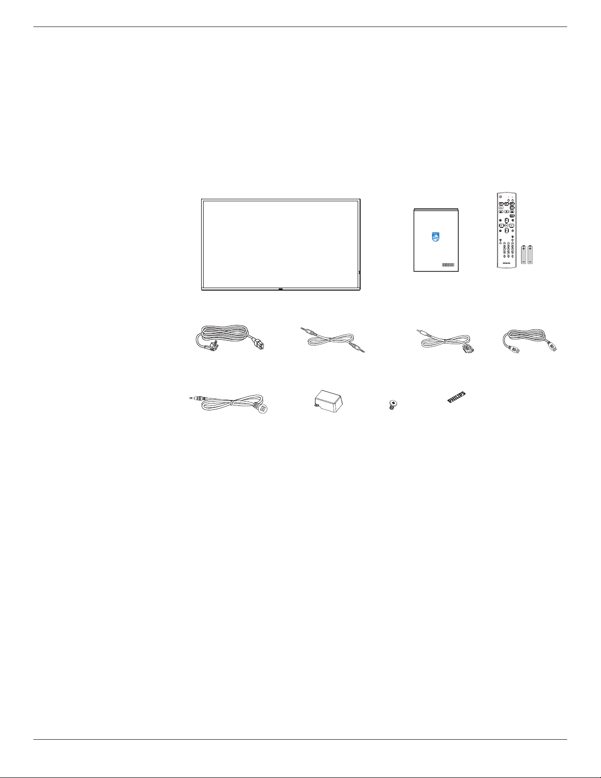
1.2. Package Contents
Please verify that you received the following items with your package content:
• LCD display
• Quick start guide
• Remote control with AAA
batteries
• Power cord
• RS232 cable
• RS232 daisy chain cable
• HDMI cable
• IR sensor cable
• USB cover and screw x2
• Philips logo plate
Quick start guide
LCD display
* The supplied power cord varies depending on destination.
NORMAL
ID
FORMAT
SOURCE
INFOLIST
OPTIONSADJUST
VOL
ID SET ENTER
Remote Control
and AAA Batteries
Power Cord RS232 Daisy Chain Cable RS232 Cable
IR Sensor Cable USB Cover Screw
Philips logo plate
HDMI Cable
* Dierences according to regions.
* Display design and accessories may dier from those illustrated above.
NOTES:
• For all other regions, apply a power cord that conforms to the AC voltage of the power socket and has been approved by and
complies with the safety regulations of the particular country.
• You might like to save the package box and packing material for shipping the display.
1.3. Installation Notes
• Only use the power cable provided with this product. If an extension cord is required, please consult your service agent.
• The product should be installed on a at surface, or the product may tip over. Leave a space between the rear of the product
and the wall for proper ventilation. Do not install the product in a kitchen, bathroom or a place exposed to moisture, failure
to do so may shorten the life of the internal parts.
• Do not install the product where it is 3000m and higher in altitude. Failure to do so may result in malfunctions.
1

43BDL3550Q_50BDL3550Q_55BDL3550Q
1.4. Mounting on a Wall
To mount this display on a wall, a standard wall-mounting kit (commercially available) is required. It is recommended that you
use a mounting interface that complies with TUV-GS and /or UL1678 standard in North America.
Protective Sheet
VESA Grid
Table
1. Spread a protective sheet which was wrapped around the display when it was packed on a at surface. Lay the display facedown on the protective sheet to facilitate your operation without scratching the screen.
2. Ensure that you have all accessories necessary for any type of mounting (wall-mounting, ceiling mounting etc).
3. Follow the instructions that come with the base mounting kit. Failure to follow correct mounting procedures could result in
damage to the equipment or injury to the user or installer. Product warranty does not cover damage caused by improper
installation.
4. For the wall-mounting kit, use M6 mounting screws (with a length 10 mm longer than the thickness of the mounting bracket)
and tighten them securely.
1.4.1. VESA Grid
43BDL3550Q
50BDL3550Q
55BDL3550Q
Caution:
To prevent the display from falling:
• For wall or ceiling mounting, we recommend that you install the display with metal brackets which are commercially
available. For detailed instructions about the installation, refer to the guide that come with the bracket.
• To prevent the display from falling in case of earthquake or other natural disaster, please contact the manufacturer of the
bracket for the mounting location.
Required space for ventilation
Leave a space of 100 mm at the top, rear, right and left for ventilation.
200(H) x 200(V) mm
400(H) x 400(V) mm
400(H) x 400(V) mm
100 mm
100 mm 100 mm
100 mm
2
43BDL3550Q_50BDL3550Q_55BDL3550Q
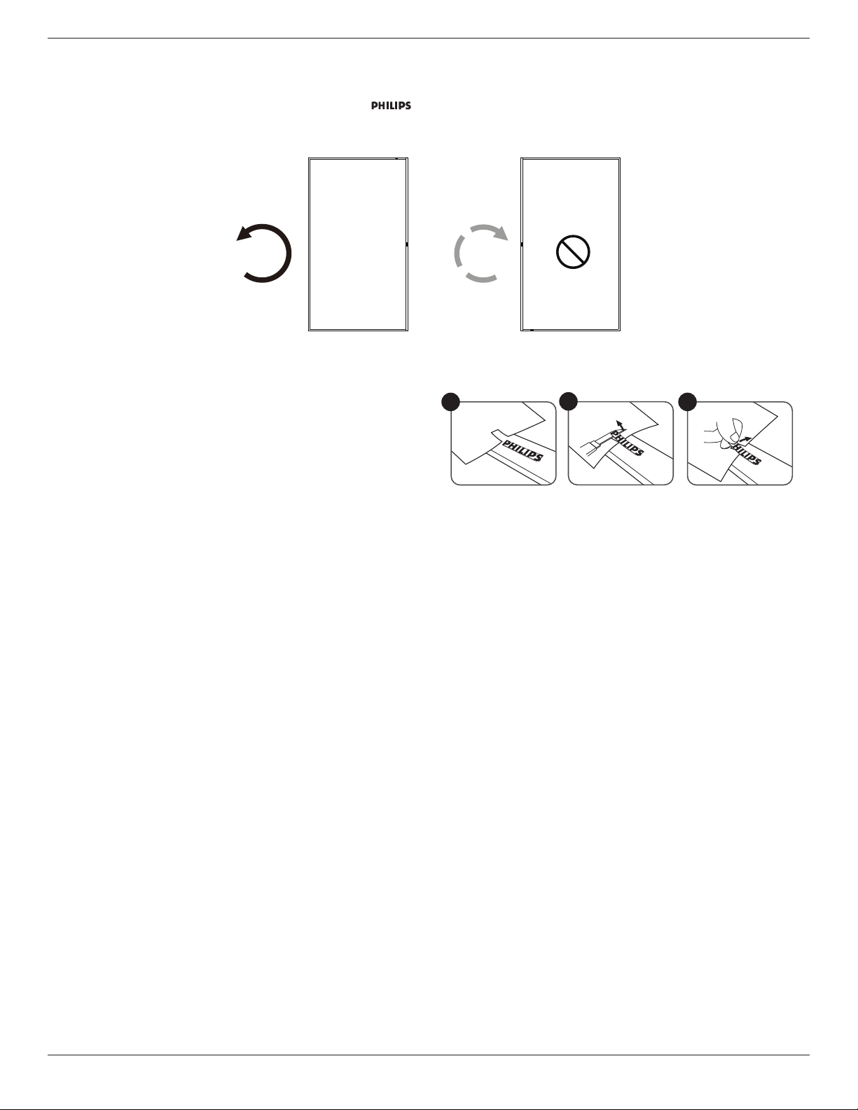
1.5. Mounting in Portrait Orientation
This display can be installed in portrait orientation.
Rotate the display 90 degrees counterclockwise. The “ ” logo should be on the right side when facing the display.
NOTE: The working hour in portrait mode is 18 hours per day.
90° 90°
1.5.1. How to remove the logo plate
1. Prepare a piece of paper with a cutting area of logo as a
protector to prevent the front bezel from scratching.
2. Use a knife and carefully remove the logo sticker with the
paper placing beneath.
3. Tear o the logo sticker.
NOTE: We recommend you contact a professional technician when installing the display on a wall. We are not responsible for
any damage to the product if the installation is not performed by a professional technician.
1
2
3
3
43BDL3550Q_50BDL3550Q_55BDL3550Q
9
2. Parts and Functions
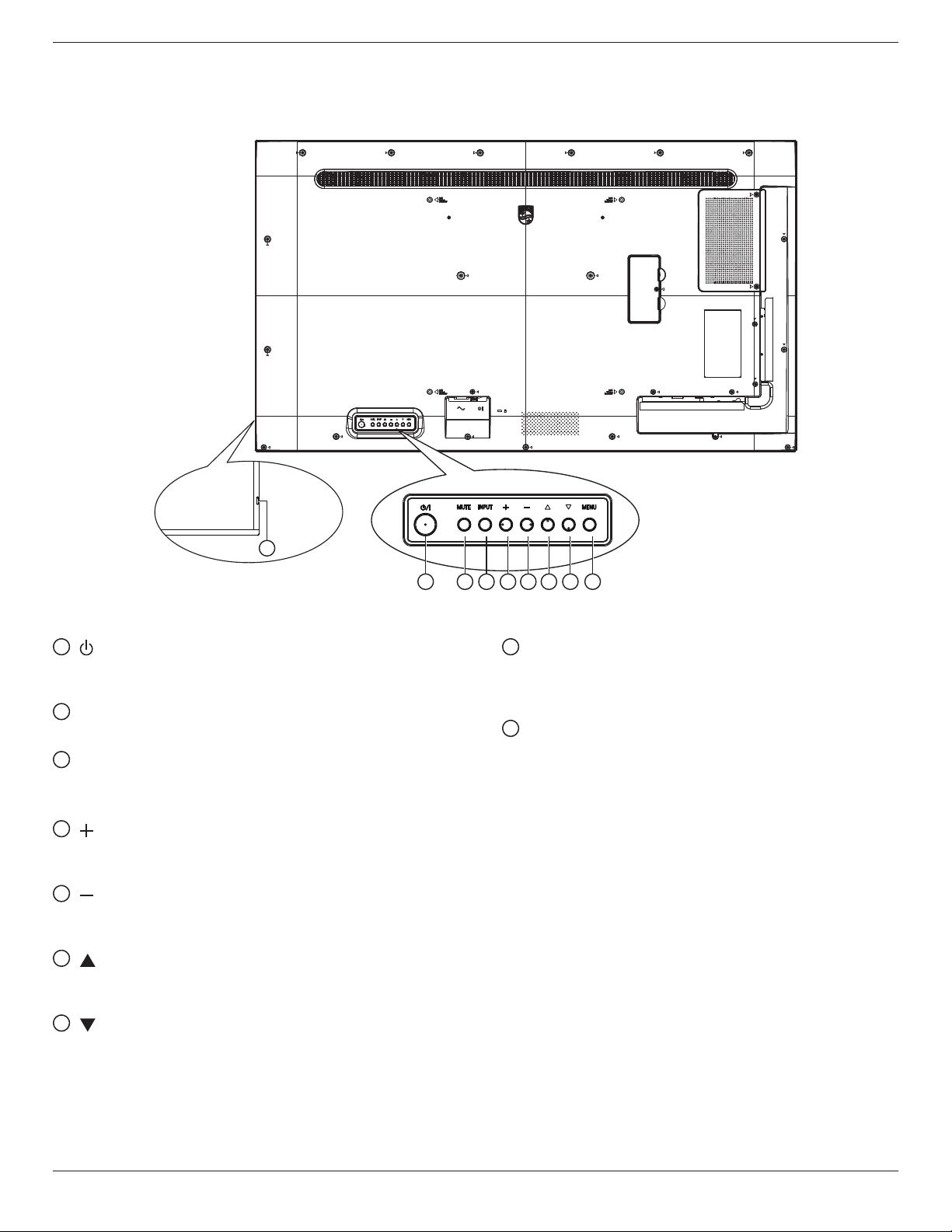
2.1. Control Panel
1
[ ] button
Press this button to turn the display On or turn the
display to standby mode.
2
[MUTE] button
Press this button to mute the sound or reactivate sound.
3
[INPUT] button
Choose the input source.
Conrm a selection in the OSD menu.
4
[ ] button
Increase the adjustment while OSD menu is on, or
increase the audio output level while OSD menu is o.
5
[ ] button
Decrease the adjustment while OSD menu is on, or
decrease the audio output level while OSD menu is o.
6
[ ] button
Move the selected item one level up while the OSD
menu is On.
7
[ ] button
Move the selected item one level down while the OSD
menu is On.
1 2 3 4 5 6 7 8
8
[MENU] button
Return to the previous menu while the OSD menu is On.
This button can also be used to activate the OSD menu
when the OSD menu is O.
9
Remote control sensor and power status indicator
• Receives command signals from the remote control.
• Indicates the operating status of the display:
- Lights green when the display is turned on.
- Lights red when the display is in standby mode.
- Lights amber when the display enters APM mode.
- When {SCHEDULE} is enabled, the light blinks green
and red.
- If the light blinks red, it indicates that a failure has
been detected.
- Lights off when the main power of the display is
turned o.
4
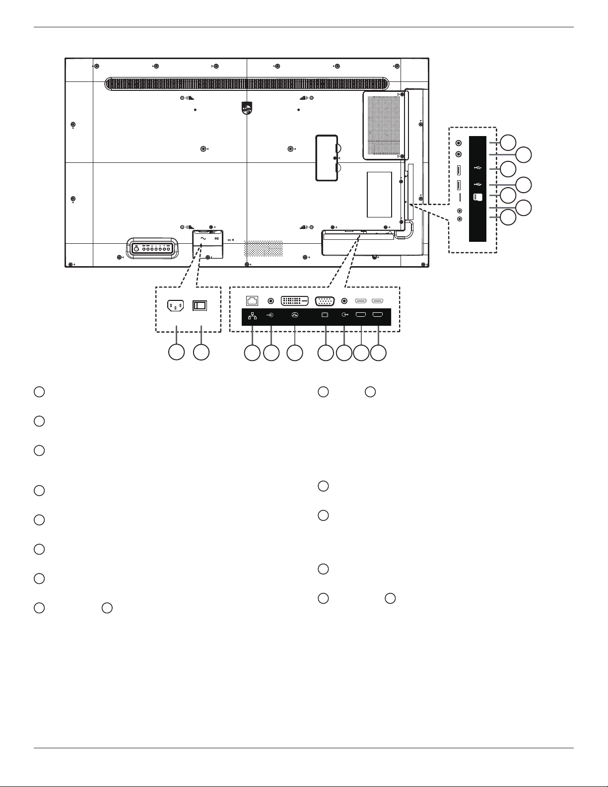
2.2. Input/Output Terminals
43BDL3550Q_50BDL3550Q_55BDL3550Q
RS232
OUT
16
RS232
Service Port
IN
USB2.0
USB
TF
IR-OUT
IR-IN
15
14
13
12
11
10
RJ45
1
1
AC IN
2
3
AC power input from the wall outlet.
2
MAIN POWER SWITCH
Switch the main power between On and O.
3
RJ-45 IN
LAN control function for the use of remote control signal
from control center.
4
PC LINE IN
Audio input for VGA source (3.5mm stereo phone).
5
DVI IN
DVI-D video input.
6
VGA IN
VGA video input.
7
AUDIO OUT
Audio output to external AV device.
8
HDMI1 IN / 9 HDMI2 IN
HDMI video/audio input.
PC LINE IN
DVI(DVI-D) IN
5 6 87 9
4
VGA IN
10
12
13
14
15
HDMI2 IN
HDMI1 IN
AUDIO OUT
IR IN / 11 IR OUT
IR signal input / output for the loop-through function.
NOTES:
• This display’s remote control sensor will stop working
if the jack [IR IN] is connected.
• To remotely control your A/V device via this display,
refer to page 14 for IR Pass Through connection.
MICRO SD CARD
Connect your MICRO SD CARD.
USB SERVICE PORT
Connect to USB storage for Android ADB Firmware
update.
NOTE: It’s for updating rmware only.
USB 2.0 PORT
Connect your USB storage device and service port.
RS232 IN / 16 RS232 OUT
RS232 network input / output for the loop-through
function.
5
43BDL3550Q_50BDL3550Q_55BDL3550Q
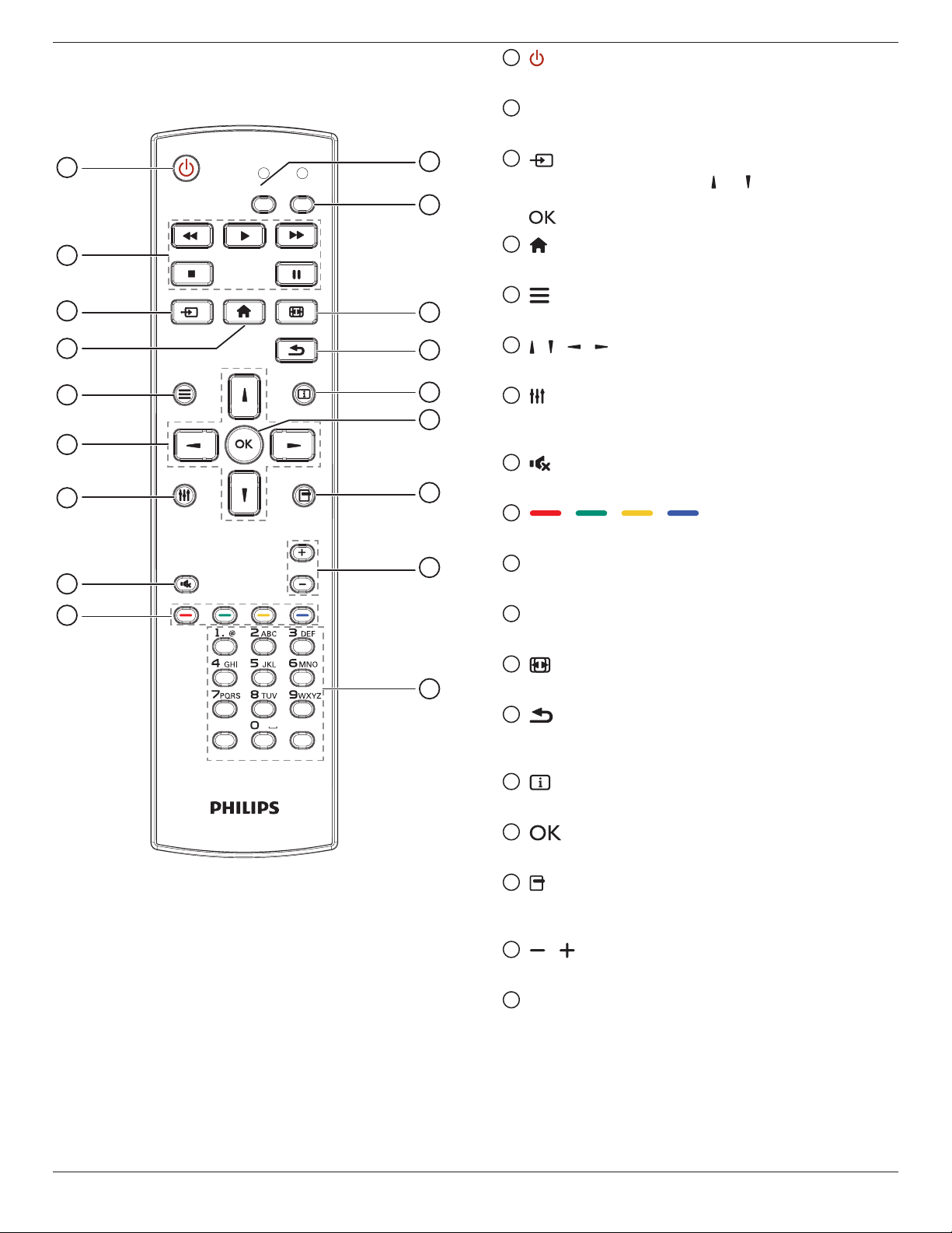
2.3. Remote Control
2.3.1. General functions
1
NORMAL
2
SOURCE
3
4
5
6
7
8
9
ID SET ENTER
ID
FORMAT
INFOLIST
OPTIONSADJUST
VOL
10
11
12
13
14
15
16
17
18
1
[ ] POWER button
Turn the display on or put the display to standby mode.
2
[PLAY] buttons
Control playback of media les.
3
[ ] SOURCE button
Choose input source. Press [ ] or [ ] button to choose
from
USB, Network, HDMI 1, HDMI 2
or
DVI-D
[ ] button to conrm and exit.
4
[ ] HOME button
Access the OSD menu.
5
[ ] LIST button
Reserved.
6
[ ] [ ] [ ] [ ] NAVIGATION buttons
Navigate through menus and choose items.
7
[ ] ADJUST button
Access currently available options, picture and sound
menus.
8
[ ] MUTE button
Press to turn the mute function on/o.
9
[ ] [ ] [ ] [ ] COLOR buttons
Choose tasks or options.
10
[NORMAL] buttons
Switch to normal mode.
11
[ID] buttons
Switch to ID mode.
12
[ ] FORMAT button
Change zoom mode.
13
[ ] BACK button
Return to the previous menu page or exit from the
previous function.
14
[ ] INFO button
Display information about current activity.
15
[ ] button
Conrm an entry or selection.
16
[ ] OPTIONS button
Access currently available options, picture and sound
menus.
17
[ ] [ ] VOLUME button
Increase or decrease the volume level.
18
[NUMERIC] buttons
Enter text for network setting, and set up ID for ID mode.
. Press
6
43BDL3550Q_50BDL3550Q_55BDL3550Q
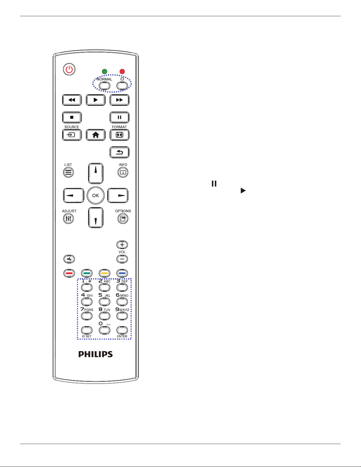
2.3.2. ID Remote Control
Set the remote control ID if you intend to use this remote
control on several dierent displays.
Press [ID] button. The red LED blinks twice.
1. Press [ID SET] button for more than 1 second to enter the
ID Mode. The red LED lights up.
Press the [ID SET] button again to exit from ID mode. The
red LED lights o.
Press the digit numbers [0] ~ [9] to select the display you
want to control.
For example: press [0] and [1] for display No.1, press [1] and [1]
for display No.11.
The numbers available are from [01] ~ [255].
2. Not pressing any button within 10 seconds will exit the
ID Mode.
3. If a wrong button is pressed, wait 1 second after the red
LED lights o and then lights up again, then press the
correct digits again.
4. Press [ENTER] button to conrm. The red LED blinks
twice and then lights o.
NOTE:
• Press [NORMAL] button. The green LED blinks twice,
indicating the display is in normal operation.
• It is necessary to set up the ID number for each display
before selecting its ID number.
• Use “ ” (pause) key on the remote control to freeze
the screen. Use “ ” (play) key on the remote control to
unfreeze the screen.
• The “freeze” feature only can be adopted on “real”
video sources like VGA, AV, YPbPr, HDMI, DVI, DP.
• Any operation on the remote control or video mode
change will unfreeze the screen.
7
43BDL3550Q_50BDL3550Q_55BDL3550Q
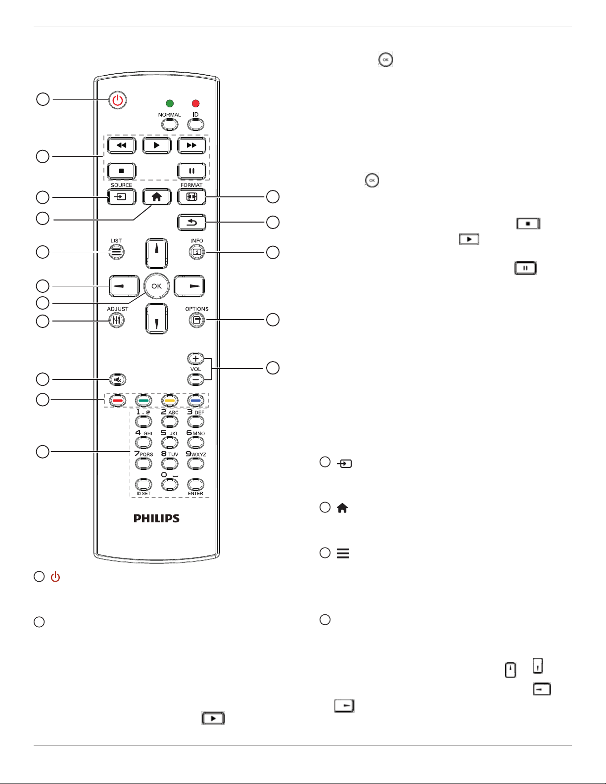
2.3.3. Remote Control buttons on Android source
1
2
3
4
5
6
7
8
9
10
11
12
13
14
15
16
3)Media Player -> Play -> choose non-empty play list
-> press to play all the media les in the play list.
4) Set media playlist in Boot on Source or Schedule by
OSD menu.
2. Play PDF le
There are 3 ways to play media les.
1) File Manager
Find the pdf le from the File Manager and select it to
play.
2) PDF Player -> Play -> choose non-empty play list ->
press to play all the PDF les in the play list.
3) Set pdf playlist in Boot on Source or Schedule by
OSD menu.
3. When playing PDF, video or music, press to
stop playing. Then if pressing again, playing will be
started from the beginning of the le.
4. When playing PDF, video or music, press button
to pause playing.
5. All media or pdf les should be put at the folder,
which is named “philips” with sub-folder, under the
root directory of the specied storage (internal/USB/
SD Card). All sub-folders (video/photo/music/pdf) are
named by media types and shouldn’t be changed.
videos: {root dir of storage}/philips/video/
photos: {root dir of storage}/philips/photo/
music : {root dir of storage}/philips/music/
pdfs : {root dir of storage}/philips/pdf/
Note that the root directories of three storages are
Internal storage: /sdcard
USB storage: /mnt/usb_storage
SD card : /mnt/external_sd
3
[ ] SOURCE button
Choose input source.
The button is only controlled by Scalar.
4
[ ] HOME button
1
[ ] POWER button
Turn the display on or put the display to standby mode.
The button is only controlled by Scalar.
2
[PLAY] buttons
1. Control playback of media(video/audio/picture) les.
There are 4 ways to play media les.
1) File Manager
Find the media le from the File Manager and select it
to play.
2) Media Player -> Compose -> edit or new add playlist
-> choose any media les -> press to play the
media le directly.
Access OSD menu.
The button is only controlled by Scalar.
5
[ ] LIST button
1. In the content of the web page, move the focus up to
the next clickable items.
2. Move the focus up to the next control or widget such
as buttons.
6
NAVIGATION buttons
1. Navigate through menus and choose items.
2. In the content of the web page, these buttons are to
control the scroll bar of the screen. Press or is
for moving vertical scroll bar up or down. Press or
is for moving horizontal scroll bar left or right.
8
3. For PDF les,
Press to go to the next page.
Press to go to the previous page.
7
[ ] button
Conrm an entry or selection.
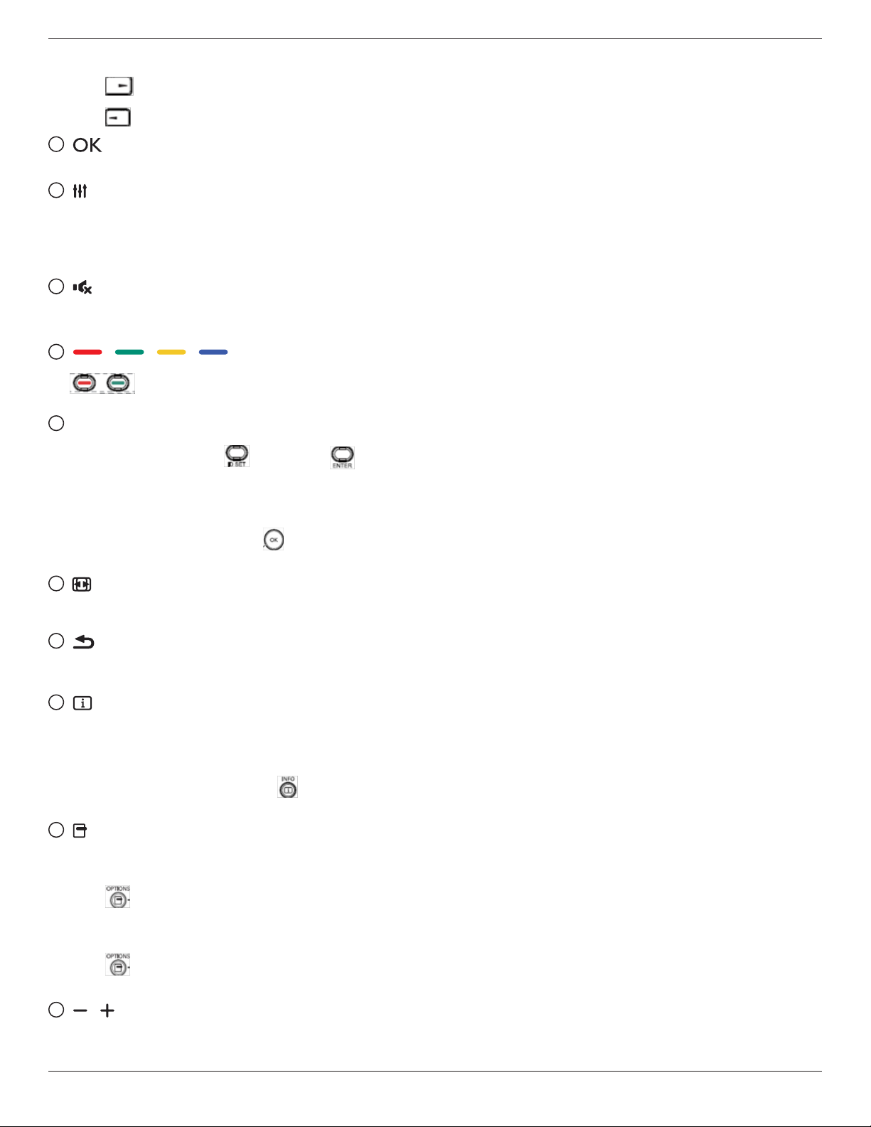
8
[ ] ADJUST button
1. In the content of the web page, move the focus down
to the next clickable items.
2. Move the focus down to the next control or widget
such as buttons.
9
[ ] MUTE button
Press to turn the mute function on/o.
The button is only controlled by Scalar.
10
[ ] [ ] [ ] [ ] COLOR buttons
: No function on Android source. These two
buttons are only controlled by Scalar.
11
[Number/ ID SET/ ENTER] button
43BDL3550Q_50BDL3550Q_55BDL3550Q
1. No functions for ID SET and ENTER on
Android source. These buttons are only controlled by
Scalar.
2. For PDF le, enter the page number by pressing
number buttons and then press button to jump to
the specic page.
12
[ ] FORMAT button
Change picture format. The button is only controlled by
Scalar.
13
[ ] BACK button
Return to the previous page or exit from the previous
function.
14
[ ] INFO button
1. Display information about current input signal. It is
shown by Scalar.
2. Media Player -> Compose -> edit or new add playlist
-> choose any media les -> press to show the
information of the chosen media le.
15
[ ] OPTIONS button
Open toolbox in Media Player or PDF Player.
1. Media Player ->Compose -> Edit or new add playlist ->
press to open toolbox. Toolbox will be slide from
the left side of the screen.
2. PDF Player ->Compose -> Edit or new add playlist ->
press to open toolbox. Toolbox will be slide from
the left side of the screen.
16
[ ] [ ] VOLUME button
Adjust volume. The buttons are only controlled by
Scalar.
9
43BDL3550Q_50BDL3550Q_55BDL3550Q
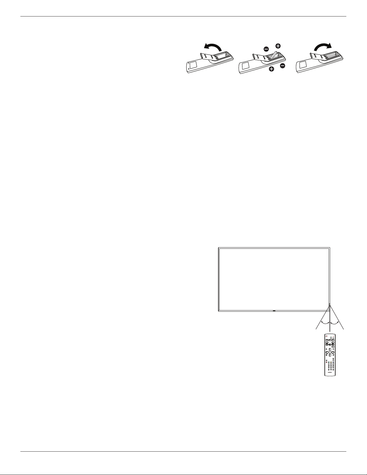
2.3.4. Inserting the batteries in the remote control
The remote control is powered by two 1.5V AAA batteries.
To install or replace batteries:
1. Press and then slide the cover to open it.
2. Insert batteries with the correct polarity (+) and (-).
3. Replace the cover.
Caution:
Incorrect use of batteries may cause leakage or explosion. Be sure to follow the instructions below:
• Insert “AAA” batteries with the correct polarity (+ and -).
• Do not mix battery types.
• Do not use a new battery with a used one together. Otherwise, it may cause leakage or shorten the life of the batteries.
• Remove the dead batteries immediately to avoid battery leakage in the battery compartment. Do not touch exposed battery
acid, as it may cause injury to your skin.
• Disposal of a battery into re or a hot oven, or mechanically crushing or cutting of a battery, that can result in an explosion;
leaving a battery in an extremely high temperature surrounding environment that can result in an explosion or the leakage of
ammable liquid or gas; and a battery subjected to extremely low air pressure that may result in an explosion or the leakage
of ammable liquid or gas.
NOTE: Remove the batteries from the battery compartment when not using for an extended period of time.
2.3.5. Handling the remote control
• Do not drop or apply shock to the remote control.
• Do not allow any liquid to get inside the remote control. If water has entered the remote control, wipe the remote control
with a dry cloth immediately.
• Do not place the remote control near heat and steam sources.
• Do not attempt to disassemble the remote control, unless you need to place batteries in the remote control.
2.3.6. Operating range of the remote control
Pointing the remote control at the remote sensor on the display.
Use the remote control within 5 m from the sensor on the display at an
angle of 20 degrees from the left and right.
NOTE:
• The remote control may not function properly when the remote control
sensor on the display is under direct sunlight or strong illumination, or
when an obstacle blocks the signal transmission.
• Use an IR sensor cable for better performance of the remote control.
(Refer to 3.4. IR connection for details)
20° 20°
10
 Loading...