

Page 1
Color TV
POWER
3
+
–
VOLUME
+
–
CHANNEL
2
1
Color TV
Quick Use and Hookup Guide
CONTENTS
Important Notice/Warning . . . . . . . . . . . . . . . . . . . .1
Basic TV Operation . . . . . . . . . . . . . . . . . . . . . . . .1
Jack Panel Descriptions and Required Cables . . . . .1
Remote Battery Installation . . . . . . . . . . . . . . . . . . .2
Remote Control Button Descriptions . . . . . . . . . . . .2
Direct Cable TV Input Connection . . . . . . . . . . . . .3
Cable TV Box Input Connections . . . . . . . . . . . . . .3
Antenna TV Connection . . . . . . . . . . . . . . . . . . . . .3
AV1 Input Jacks Connections . . . . . . . . . . . . . . . . .4
AV2 Input Jacks Connections . . . . . . . . . . . . . . . . .4
AV5 Input Jacks including DVI Connections . . . . .5
AV4 Input Jacks Connections . . . . . . . . . . . . . . . . .6
AV3 Side Input Jacks Connections . . . . . . . . . . . . .6
Component Video Input Jacks Connections . . . . . . .7
S-Video Input Connection . . . . . . . . . . . . . . . . . . . .7
Monitor Output Jack Connections . . . . . . . . . . . . . .8
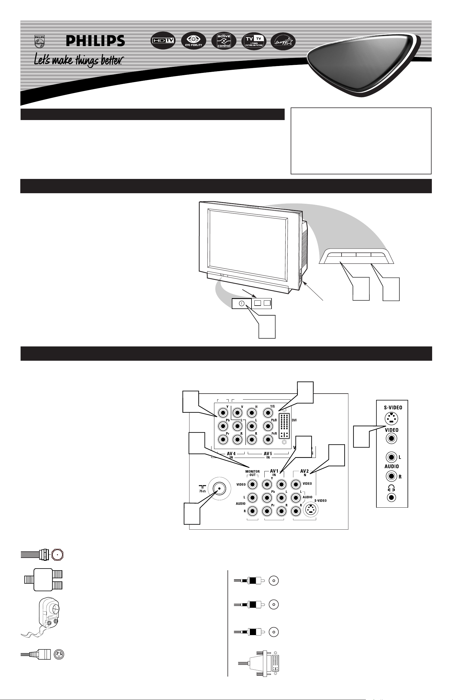
BASIC TV OPERATION
our television has a set of controls located on the top and
Y
front of the cabinet for use when the remote control is not
needed.
Press the POWER button on the front of the TV cabinet to
turn the TV ON.
1
Note: With AutoChron ON, the TV will search for a PBS channel to set the clock before powering itself on. This can take several seconds.
Press the VOLUME + button to increase the sound level or
the VOLUME – button to lower the sound level.
2
Pressing both buttons at the same time will display the
onscreen menu. After you are in the menu, use these buttons to
make adjustments or selections.
Press the CHANNEL + or – button to select TV channels.
Use these buttons to make adjustments or selections in the
3
onscreen menu.
There is also a set of Audio and Video Input jacks located on the side
of the television cabinet. Refer to the Side AV3 Input section on page 6
of this Quick Use and Hookup Guide.
IMPORTANT
NOTE: This owner's manual is used with several different television models. Not all features (and drawings)
discussed in this manual will necessarily match those
found with your television set. This is normal and does
not require that you contact your dealer or request service.
WARNING: TO PREVENT FIRE OR SHOCK HAZARD DO NOT EXPOSE THIS UNIT TO RAIN OR
EXCESSIVE MOISTURE.
Volume and Channel buttons are located
on the top of the television cabinet.
Remote Sensor Window
Audio, Video, S-Video
and Headphone Jacks
located on the side of
the television.
JACK PANEL DESCRIPTIONS AND REQUIRED CABLES
he television is equipped with external input and output jacks
T
for use with optional accessory devices such as Home entertainment Receivers, VCRs, DVD Player, Gaming Units, Video
Cameras, etc.
75Ω RF - Cable/Antenna Input connection jack.
1
AV 1 IN - Audio/Video connection jacks including
Component Video Inputs.
2
AV 2 IN - Audio/Video Input connection jacks including
S-Video connections.
3
AV 5 IN - High Definition 1080i or 480p Video, DVI
(Digital Video Input), Audio Inputs, Horizontal and Vertical
4
Sync connection jacks.
AV 4 IN - High Definition 1080i or 480p Video and Audio
Input connection jacks.
5
Monitor Out - Audio/Video Output connection jacks (TV
tuner signal only).
6
SIDE (AV 3) - Audio/Video Input jacks include a S-Video
jack, plus a Headphone jack located on the side of the cabi-
7
net.
5
6
1
Located on the back of the TV
HD1
HD2
4
7
2
3
Located on the side of the TV
A 75-ohm coaxial cable connects signals from an antenna or a
cable TV company to the antenna jack on the back of the TV.
Coaxial cables use “F” connectors.
A two-way signal splitter enables you to take a single antenna or
cable TV signal and supply it to two different inputs.
A 300- to 75-ohm twin-lead adapter accepts the antenna cables
(called twin-lead wires) from an antenna, allowing you to connect
the antenna signal to the TV.
A S-Video cable provides better picture performance than regular
(composite) video connections.
S-Video cables can be used only with S-Video-compatible accessory devices. You must also connect the left and right audio
cables to the AV 2 Audio in jacks because the S-Video jack carries only the picture signal, not the sound.
White - Audio Left
Red - Audio Right
3121 233 44011
Yellow - Video
Video and audio cables with standard RCA (phono) connectors connect the video and audio jacks of accessory devices
such as VCRs and DVD players to the jacks on the TV.
These connectors are usually color coded. The jacks on your
TV are also color coded to match the colors of the connectors.
Yellow for video (composite) and Red and White for the right
and left audio channels. The video cables used to connect component video or RGB (high-resolution) jacks are color coded
red, green, and blue.
A DVI (Digital Video) cable that will support digital connec-
tion from a PC. Only Single Digital Link DVI is supported for
PCs with 480p or 1080i output.
Page 2
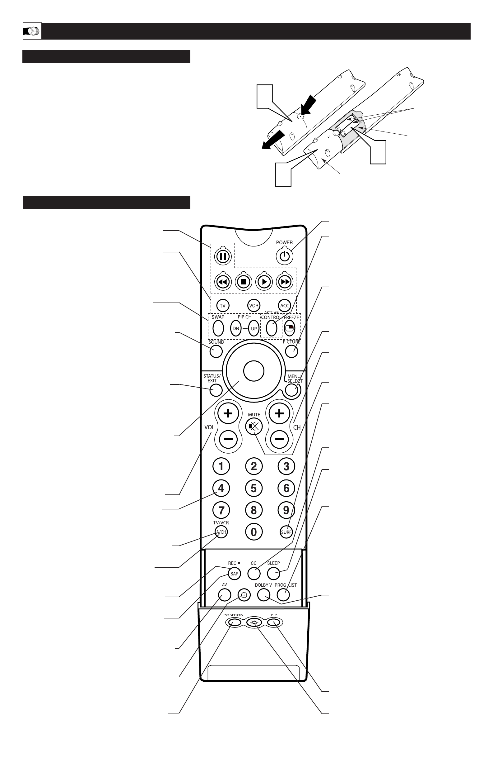
BASIC REMOTE CONTROL OPERATION
REMOTE
o load the supplied batteries into the remote:
CONTROL BATTERIES
T
Remove the battery compartment door on the back of the
remote.
1
Place the batteries (2-AA) in the remote. Be sure the (+) and
(–) ends of the batteries line up correctly (the inside of the case
2
is marked).
Reattach the battery compartment door.
3
REMOTE CONTROL BUTTONS
VCR control buttons - Press to pause, rewind,
stop, play, or fast forward a videotape.
TV • VCR • ACC - (Mode buttons) Press to send
remote signals to either the TV, VCRs, or other accessory
devices such as cable TV converters, satellite receivers,
DVDs, or laser disc players. (You may need to program
the remote to work accessory devices. Refer the Directions
for Use manual.
PIP buttons: SWAP, PIP CH DN/UP,
FREEZE - Press to operate the Picture-in-Picture (PIP)
features.
Be sure to point the remote at the Remote Sensor window on
the front of the television when using the remote control to
operate the television.
1
2 “AA” Batteries
Remote Control
(shown from the bottom)
Battery Compartment
2
Battery Compartment Door
3
Power - Press to turn the TV on or off.
Active Control™ - Measures and corrects all
incoming signals to provide the best picture-quality
settings. Press to turn Active Control™ on or off.
When Active Control™ is on, it automatically and
continuously controls Sharpness and Noise Reduction
settings.
Picture - Press to select an AutoPicture™ control.
Choose from four factory-set controls—Movies,
Sports, Weak Signal, and Multimedia—and a PERSONAL control that you set according to your own
preferences through the onscreen Picture menu.
Sound
from three factory-set controls—Voice, Music, and
Theatre—and a Personal control that you set according to
your own preferences through the onscreen Sound menu.
The three factory-set controls will tailor the TV sound so
as to enhance the type of program you are watching.
- Press to select an AutoSound™ control. Choose
Status/Exit - Pressing the button once shows the cur-
rent channel number, name (if set), time (if set), Sleep
Timer setting, and sound setting (stereo, mono, SAP, or
mute). Pressing the button twice shows the current
AutoLock™ settings. Pressing the button once when an
onscreen display is showing removes the onscreen display.
Cursor Ring - Up/Down: allows you to select the next
or previous menu item in the menu. Left/Right: allows you
to access the submenus and adjust the settings. When no
onscreen displays or menus are present, use the Cursor
Ring Left/Right to select a picture format for a video
source connected to the ANTENNA, AV1, CVI, AV2, or
AV3 (side panel inputs) on the TV.
Volume (+/–) - Press to adjust the TV sound level.
Number Buttons - Press to select TV channels.
When selecting single-digit channels, press the number of
the desired channel. The TV will pause for a few seconds
and then tune to the selected channel.
TV/VCR - Press while in VCR mode to view the play-
back of a videotape. Press again to return to TV mode.
A/CH - When in the TV mode, press to alternate
between the currently viewed channel and the previously
viewed channel.
Menu/Select - Press to display the onscreen
menu. Press to return to a higher menu level.
Channel (+/–) - Press to select channels in
ascending or descending order or cycle through the
signal inputs.
Mute - Press to turn the TV sound off. To restore the
sound to its previous level, press the button again.
Surf - Press to select previously entered channels.
With the TV’s AutoSurf™ control, you can place up
to 10 favorite channels or sources in memory. Then by
pressing the Surf button, you can quickly view the
selected channels.
CC Button - Press to select Closed Captioning
options within the menu.
Sleep - Press to set the TV to automatically turn
itself off after a period of time. Choose 15, 30, 45, 60,
90, 120, 180, or 240 minutes before the TV will automatically turn off.
Program List - Press to display a list of channel
numbers and their names. Each channel will appear as
a selectable menu item. The current channel will be
highlighted as default. Five channels will be listed on
screen at one time. Press the Cursor Ring up or down
to scroll the list and and highlight a channel. Press the
Cursor Ring right to tune to the highlighted channel.
Channels marked “Skipped” in the Channel Edit control will not appear in the list. Each channel that is
being blocked by AutoLock™ will appear with a padlock icon to indicate that the channel is not viewable.
¶¶
Rec
button when in VCR mode to record.
- Press this button simultaneously with the 3
SAP - When in the TV mode, press to select between
main sound and SAP (Second Audio Program) when you
tune to a program offering SAP.
AV - Press repeatedly to select the different signal sources
connected to the TV: TV (current channel), AV1, CVI,
AV2, AV3 (side jack panel), AV4 and AV5.
Clock - Press to access the onscreen Timer menu, where
you can set the time for the TV’s clock or set the TV’s
Timer features, such as channel switch over, power on set,
and power off set.
Position - Press to move the PIP picture to any of the
four corners of the screen.
Dolby V - Press to select various factory surround
sound listening modes.
Dolby* Virtual (Virtual Dolby Surround)
(with Virtual Dolby Surround signals) - Dolby
Virtual uses two speakers to simulate the surround
effect produced by a multichannel system.
Incredible Surround™ - In Stereo sound
mode—when Incredible Surround™ is turned on—
it seems as though the loudspeakers are spread farther apart from each another. In Mono sound
mode—when Incredible Surround™ is turned on—
enables you to hear a spatial sound effect.
PIP - Press to turn PIP (picture-in-picture) on or off
or control the size of the PIP window.
Back Light button - Press to light the buttons
on the remote control.
2
Page 3

OOKING UP THE TELEVISION
1
2
HD1
HD2
HD1
HD2
OUTPUT
INPUT
3
4
1
2
HD1
HD2
1
3
2
H
DIRECT CABLE TV INPUT
our Cable TV input into your home may be a single (75
ohm) cable or a converter box installation. In either
Y
case, the connection to the TV is very easy. Follow the steps
below to connect your cable signal to your new television.
If your cable signal comes directly from a round 75Ω coaxial
cable use the following steps:
Connect the open end of the round Cable Company
supplied cable to the 75Ω input on the TV. Screw it down
1
finger tight.
Plug the television into the wall outlet and turn the TV
on. Refer to the AUTOPROGRAM feature to program all
2
the available channels on your cable signal.
CABLE TV BOX INPUT
If your cable signal comes from a cable box, use the following
steps: (This connection will be mono. Some Cable boxes use
Left and Right channel audio output jacks for stereo connections. This type of Cable Box can be connected to the AV1 or
AV2 Audio Left and Right Audio Inputs. Please refer to your
Cable Box instructions.)
Connect the open end of the round Cable Company
supplied cable to the cable signal IN(put) plug on the back
1
of the Cable Box.
Direct Cable
Connection:
Cable signal coming from
Cable Company (Round
75Ω coaxial cable)
Jack Panel
Back of TV
Cable Box Connection:
Round 75Ω
Coaxial Cable
AC Power
Wall Outlet
Power Plug
from back of TV
Jack Panel Back
of Cable Box
Cable Box
Power Cord
AC Power
Wall Outlet
Jack Panel
Back of TV
Using a separate round coaxial cable, connect one end to
the OUT(put) plug on the back of the Cable Box.
2
Connect the other end of the round coaxial cable to the
75Ω input on the back of the television. Screw it down fin-
3
ger tight.
Plug the television into the wall outlet and turn the TV
on. Refer to the TUNER and AUTOPROGRAM features
4
on page 4 of this Quick Use Guide. TUNER should be set
to the CABLE option. AUTOPROGRAM can be set to program all the available channels on your cable signal into
the television’s memory.
CABLE
This connection will supply Stereo sound to the TV.
Connect the open end of the round Cable Company sup-
plied cable to the cable signal IN(put) plug on the back of
1
the Cable Box.
Using a RCA type Video Cable, connect one end of the
cable to the Video (or ANT, your cable box may be labeled
2
differently) Out jack on the cable box and the other end to
the AV1 Video Input on the TV.
Using a RCA type Audio Left and Right Cable, connect
one end to the left and right Audio Out L & R jacks on
3
the cable box. Connect the other end to the AV1 Audio L
& R Input jacks on the TV.
TV B
OX WITH A/V INPUTS
Cable Signal IN from
the Cable Company
Cable Signal IN
from the Cable
Company
Video Cable
(Yellow)
The signal coming
from the box will
be MONO.
HD1
HD2
Power Plug
from back of TV
Jack Panel Back
of Cable Box with A/V Outputs
Audio Cables
L & R
(Red, White)
NOTE: Use the AV button on the TV remote control to tune to the
AV1 channel for the cable box signal. Once tuned, change channels at the cable box, not the television. Pressing the AV button
repeatedly will scroll all the AV Input channels, including the
presently tuned channel.
NTENNA TV
A
combination antenna receives normal broadcast channels (VHF 2–13 and UHF 14–69). Your connection is
A
easy because there is only one 75Ω (ohm) antenna plug on
the back of your TV, and that’s where the antenna goes.
If your antenna has a round cable (75 ohm) on the end,
then you're ready to connect it to the TV.
1
If your antenna has flat, twin-lead wire (300 ohm), you
first need to attach the antenna wires to the screws on a
300- to 75-ohm adapter.
Push the round end of the adapter (or antenna) onto the
75Ω (ohm) plug on the back of the TV. If the round end of
2
the antenna wire is threaded, screw it down finger tight.
Plug the television into the wall outlet and turn the TV
on.
3
Refer to the TUNER and AUTOPROGRAM features on
page 4 of this Quick Use Guide. TUNER should be set to the
ANTENNA option. AUTOPROGRAM can be set to program
all the available channels on your cable signal into the television’s memory.
Antenna Connection:
Outdoor or Indoor Antenna
(Combination VHF/UHF)
The combination antenna receives normal
broadcast channels 2-13 (VHF) and 14-69 (UHF).
300 to 75-ohm
Adapter
Twin
Lead Wire
Round 75Ω Coaxial
Cable from Antenna
Jack Panel, Back of TV
Jack Panel Back of TV
AC Power
Wall Outlet
Power Plug
from back
of TV
3
Page 4

OOKING UP THE TELEVISION
H
USING THE AV 1 INPUT JACKS
he TV’s audio/video input jacks are for direct picture and
T
sound connections between the TV and a VCR (or similar
device) that has audio/video output jacks. Follow the easy steps
below to connect your accessory device to the AV 1 Input Jacks
located on the back of the TV.
Connect the VIDEO (yellow) cable to the VIDEO AV1 IN
jack on the back of the TV.
1
Connect the AUDIO (red and white) cables to the
AUDIO (left and right) AV1 IN jacks on the rear of the TV.
2
Connect the VIDEO (yellow) cable to the VIDEO OUT
jack on the back of the VCR.
3
Connect the AUDIO (red and white) cables to the
AUDIO (left and right) OUT jacks on the rear of the VCR.
4
Tu rn the VCR (accessory device) and the TV ON.
5
Press the AV button on the remote control to tune the AV1
channel.
6
AV1
BACK OF TV
HD1
BACK OF VCR
HD2
2
AUDIO IN
(RED/WHITE)
1
VIDEO IN
(YELLOW)
Insert a prerecorded tape (or CD, DVD, depending on
the type of accessory device being used) and, press the
7
PLAY button on the accessory device to view the playback.
SING THE AV 2 INPUT JACKS
U
he TV’s audio/video input jacks allow you connect multiple
T
accessory devices at one time to different sets of input jacks..
Follow the easy steps below to connect an additional accessory
device to the AV 2 Input Jacks located on the back of the TV.
AV2
6
5
ANT/CABLE
OUT
S-VIDEO
OUT
4
(EQUIPPED WITH VIDEO AND
AUDIO OUTPUT JACKS)
HD1
HD2
VCR
R L
AUDIO OUT
VIDEO
OUT
3
7
BACK OF TV
Connect the VIDEO (yellow) cable to the VIDEO AV2 IN
jack on the back of the TV.
1
Connect the AUDIO (red and white) cables to the
AUDIO (left and right) AV2 IN jacks on the rear of the TV.
2
Connect the VIDEO (yellow) cable to the VIDEO OUT
jack on the back of the VCR.
3
Connect the AUDIO (red and white) cables to the
AUDIO (left and right) OUT jacks on the rear of the VCR.
4
Turn the VCR (accessory device) and the TV ON.
5
Press the AV button on the remote control to tune to the
AV2 channel.
6
Insert a prerecorded tape (or CD, DVD, depending on
the type of accessory device being used) and, press the
7
PLAY button on the accessory device to view the playback.
6
ANT/CABLE
S-VIDEO
OUT
OUT
CONNECTED TO AV1 INPUTS
AUDIO IN
(RED/WHITE)
R L
AUDIO OUT
FIRST VCR
2
VIDEO
OUT
1
VIDEO IN
(YELLOW)
ANT/CABLE
OUT
4
S-VIDEO
OUT
R L
AUDIO OUT
BACK OF 2ND VCR
VIDEO
OUT
3
5
7
SECOND VCR or ACCESSORY DEVICE
(EQUIPPED WITH VIDEO AND AUDIO OUTPUT JACKS)
4
Page 5

OOKING UP THE TELEVISION
H
USING THE AV 5 INPUT JACKS
he AV5 Input Jacks provide High Definition Video Inputs at
T
1080i or 480p, for accessories like a HD Receiver and Digital
DVD Players. There is also a DVI jack supplied allowing encrypted transmission of uncompressed HD content. .
Connect the Component (Y, Pb, Pr) Video OUT jacks
from the HD accessory device to the (Y, Pb, Pr) AV5
1
IN(put) jacks on the TV. If the device your using is
equipped with separate Horizontal and Vertical sync, connect the H and V Outputs on the accessory device to the H
and V Inputs of AV5 IN.
Connect the red and white AUDIO CABLES to the Audio
(left and right) output jacks on the rear of the HD accessory
2
device to the Audio (L and R) AV5 IN(put) jacks on the TV.
Connect a DVI cable from the DVI OUT on the HD accessory device to the AV5 DVI jack on the back of the TV.
3
Connect a 75Ω round cable from the OUT TO TV jack on
the HD accessory device to the 75Ω IN on the back of the
4
TV.
If using a Satellite Dish, Cable signal or Antenna signal,
connect the 75Ω round cable from a Satellite Dish to the
5
SATELLITE IN and/or the Cable and Antenna signals to the
ANTENNA “A” or “B” IN on the back of the HD accessory
device.
Press the AV button on the remote control repeatedly to
tune to the AV5 channel.
6
Note: If the AV5 channel is tuned and no signal
connection present, the screen could jump or flash.
HORIZONTAL
AND VERTICAL
SYNC CABLES
AUDIO IN
(RED/WHITE)
COMPONENT
VIDEO
CABLES
1
Y
COMPONENT VIDEO
H
SATELLITE
IN
SYNC OUT
JACK PANEL
ON BACK OF TV
DVI CABLE
2
HD1
1
HD2
3
4
BACK of
ACCESSORY
DEVICE
Pb
Pr
V
DIGITAL AUDIO
OUTPUT
PHONE JACK
VCR
CONTROL
L
R
L
R
VIDEOAUDIO
OUT TO TV
2
S-VIDEO
ANTENNA BINANTENNA A
5
IN
Your now ready to use your digital device to begin playback of
high definition quality.
NOTE: This television is designed to accept high definition signals 1080i and 480p as specified by the Electronic Industries
Association standard EIA770.3. Digital devices from different
manufacturers have the possibility of differing output standards
which my cause difficulties for the television to properly display.
cc
HECK IT OUT
C
DVI - DVI is a specific digital input allowing encrypted transmission of uncompressed HD content. DVI includes HDCP
(high-bandwidth digital content protection), which is supported
by Hollywood, satellite providers, and most of the consumer
electronics industry. DVI is gaining momentum and quickly
becoming an industry standard for the consumer to view highdefinition material while keeping content protected.
NOTE: The Picture-in-Picture (PIP) feature is not available for
use with AV5.
COAXIAL CABLE
LEAD-IN FROM
SATELLITE DISH
AV5
5
COAXIAL CABLE
LEAD-IN FROM
ALTERNATE RF
SIGNAL SOURCE
5
COAXIAL CABLE
LEAD-IN FROM CABLE
OUTLET, CONVERTER BOX,
OR VHF/UHF ANTENNA
6
5
Page 6

OOKING UP THE TELEVISION
H
USING THE AV 4 INPUT JACKS
he AV4 Input Jacks provide High Definition Video Inputs at
T
1080i or 480p, for accessories like a HD Receiver and Digital
DVD Players. Using the color difference signals (Pb, Pr) and the
luminance (Y) signal will improve color bandwidth information.
Connect the Component (Y, Pb, Pr) Video OUT jacks
from the DVD player (or similar device) to the (Y, Pb, Pr)
1
AV4 IN(put) jacks on the TV.
Connect the red and white AUDIO CABLES to the
AUDIO (left and right) OUT(put) jacks on the rear of the
2
accessory device to the Audio (L and R) AV4 IN(put) jacks
on the TV.
Press the AV button on the remote control repeatedly to
tune to the AV4 channel.
3
Tu rn the TV and the DVD (or digital accessory device)
ON.
4
Press the PLAY button on the DVD (or digital accessory
device) to view the program on the television.
5
Note: If the AV4 channel is tuned and no signal connection present, the screen could jump or flash.
1
AV4
HD1
COMPONENT
CABLES
HD2
VIDEO
JACK PANEL
ON BACK OF TV
2
AUDIO IN
(RED/WHITE)
NOTE: This television is designed to accept high definition signals 1080i and 480p as specified by the Electronic Industries
Association standard EIA770.3. Digital devices from different
manufacturers have the possibility of differing output standards
which my cause difficulties for the television to properly display.
USING THE SIDE AV 3 INPUT JACKS
his television has input jacks conveniently located on the side
T
of the cabinet. These jack are for easy hook-ups (without having to move around to the back of the TV) for cameras, gaming
units, and other accessory devices that wouldn’t be connected
permanently. Follow the easy steps below to connect your accessory device to the SIDE Input Jacks located on the right side of
the TV.
AV3
3
AV3
1
Y
4
COMP VIDEO
Pb
Pr
JACK PANEL
OF DIGITAL DEVICE SUCH
AS A DVD PLAYER
EQUIPPED WITH
COMPONENT VIDEO
S-VIDEO
OUT
OUTPUTS
AUDIO
VIDEO
OUT
OUT
SIDE (AV 3) Input Jacks
Located on the Side of
the Television Cabinet
R
L
5
2
Connect the VIDEO (yellow) cable to the VIDEO IN jack
on the side of the TV.
1
Connect the AUDIO (red and white) cables to the
AUDIO (left and right) IN jacks on the side of the TV.
2
Connect the VIDEO (yellow) cable to the VIDEO OUT
jack on the back of the camera (or accessory device).
3
Connect the AUDIO (red and white) cables to the
AUDIO (left and right) OUT jacks on the rear of the cam-
4
era (or accessory device).
Turn the camera (or accessory device) and the TV ON.
5
Press the AV button on the remote control repeatedly to
tune to the AV3 channel.
6
With the camera (or accessory device) ON and a prerecorded tape (or other media depending on type of accesso-
7
ry device being used) inserted, press the PLAY button to
view the tape on the television.
NOTE: The S-Video Cable can be used in place of the Yellow
Video cable shown in this diagram. If your camera or accessory
device has a S-Video output jack, connecting the video signal
through the S-Video jack will reproduce the video signal with
greater quality.
6
Jack Panel of
Camera
or External
Accessory Device
1
2
VIDEO IN
(YELLOW)
3
S-VIDEO
7
VIDEO
AUDIO
LEFT RIGHT
AUDIO IN
(RED &
WHITE)
4
The SIDE
JACKS also
contain a
HEADPHONE
JACK.
5
6
Page 7

HOOKING UP THE TELEVISION
COMPONENT VIDEO INPUT (CV1)
f using an accessory device that is not high definition but uses
I
Component Video jacks. The AV1 jacks on the TV offer the user
the possibility of better video reproduction using the Component
Video Inputs. The color difference signals (Pb, Pr) and the luminance (Y) signal are connected and received separately, which
allows for improved color bandwidth information (not possible
when using composite video or S-Video connections).
Connect the Component (Y, Pb, Pr) Video OUT jacks
from the DVD player (or similar device) to the (Y, Pb, Pr)
1
IN(put) jacks on the TV. When using the Component Video
Inputs, it is best not to connect a signal to the AV1 Video
Input.
Connect the yellow VIDEO CABLE along with the red
and white AUDIO CABLES to the AUDIO (left and
2
right) OUT(put) jacks on the rear of the accessory device
to the AV1 VIDEO and AUDIO IN(put) jacks on the TV.
Press the AV button on the remote control repeatedly to
tune to the CVI channel.
3
Turn the TV and the DVD (or digital accessory device)
ON.
4
Insert a DVD disc into the DVD player and press the
PLAY 䊳 button on the DVD Player (or digital accesso-
5
ry device).
CVI
HD1
COMPONENT
VIDEO
CABLES
COMP VIDEO
Y
HD2
1
BACK OF TV
2
AUDIO IN
(RED/WHITE)
S-VIDEO
Pb
OUT
Pr
VIDEO
OUT
AUDIO
R
OUT
L
HELPFUL HINT
The description for the component video connectors may differ
depending on the DVD player or accessory digital source
equipment used (for example, Y, Pb, Pr; Y, B-Y, R-Y; Y, Cr,
Cb). Although abbreviations and terms may vary, the letters b
and r stand for the blue and red color component signal connectors, and Y indicates the luminance signal. Refer to your
DVD or digital accessory owner’s manual for definitions and
connection details.
S-VIDEO INPUT
he S(uper)-Video connection on the rear of the TV can provide
you with better picture detail and clarity for the playback of
T
accessory sources such as DBS (digital broadcast satellite), DVD
(digital video discs), video games, and S-VHS VCR (video cassette recorder) tapes than the normal antenna picture connections.
AV2
3
1
4
HD1
ACCESSORY DEVICE
COMPONENT VIDEO
HD2
EQUIPPED WITH
OUTPUTS.
VIDEO
(YELLOW)
CABLE
5
2
JACK PANEL
ON BACK OF TV
NOTE: The accessory device must have an S-VIDEO OUT(put)
jack in order for you to complete the connection on this page.
Connect the S-VIDEO CABLE to the S-VIDEO input jack
on the rear of the television.
1
Connect the AUDIO (red and white) cables to the AUDIO
AV2 IN jacks on the rear of the TV
2
Connect the S-VIDEO CABLE to the S-VIDEO
OUT(put) jack on the accessory device.
3
Connect the red and white AUDIO cables to the AUDIO
(left and right) OUT(put) jacks on the rear of the accessory
4
device.
Press the AV button on the remote control repeatedly to
tune the AV2 channel. The S-Video Input is dominate over
5
the AV2 Video Input.
Turn the VCR, DVD or other accessory device ON.
.
6
With the VCR (or accessory device) ON and a prerecorded
tape inserted, press the PLAY button to view the tape on
7
the television.
5
AUDIO CABLES
(Red & White)
4
L R
AUDIO OUT
2
S-VIDEO
CABLE
VIDEO
OUT
S-VIDEO
OUT
1
When using the S-Video Input, do not
connect a video signal to the AV 2 IN
Video Jack. This could cause a ghost
image to appear over the S-Video signal.
ANT/CABLE
OUT
3
cc
HECK IT OUT
C
The S-Video jack and the AV 2 jacks work together. When a
device is connected to the S-Video jack, do not connect a signal to
the AV 2 IN Video jack. This could cause an over-lapping of two
video images on the TV screen.
VCR or EXTERNAL
ACCESSORY DEVICE
6
7
WITH S-VIDEO OUTPUT
7
Page 8

OOKING
H
MONITOR OUTPUT JACKS
SECOND VCR FOR RECORDING
he Audio/Video (Monitor) Output jacks can be used for
T
recording a selected TV (Antenna Input/tuner signal source)
Channel. This recording can even be completed while viewing
another external Audio/Video Source Select option. (For example:
DVD program playback shown through the A/V 1 or 2 Input
source connection.)
NOTE: Refer to page 4 for the proper hookup of an accessory
device to the AV 1 IN(put) jacks. Follow the instructions on how
to tune to the AV 1 channel to view a DVD program playback or
pre-recorded VCR tape.
UP THE TELEVISION
HD1
HD2
MONITOR OUT
VIDEO &
AUDIO L(eft) and R(ight)
JACK PANEL
Located on the
back of the TV
The following steps allow you to connect a VCR to record a
selected TV channel program through the Monitor Outputs.
Connect one end of the yellow Video Cable to the
Monitor Out VIDEO plug. Connect the other end to the
1
VIDEO IN plug on the VCR.
Connect one end of the red and white Audio cable from
the Monitor Out AUDIO L and R plugs on the TV to the
2
AUDIO IN plugs on the VCR.
Tune the TV to the program channel you wish to record
by pressing the AV or NUMBERED buttons.
3
Note: Once selected be sure to leave the TV channel tuned
to the desired program until the complete recording is finished.
Turn the recording VCR ON, insert a blank VHS tape
and it’s ready to record the channel program you selected
4
previously in step #3.
MONITOR OUTPUT JACKS
EXTERNAL AUDIO SYSTEM
3
4
Recording
VCR
1
VIDEO CABLE
(Yellow)
ANTENNA
IN
ANTENNA
OUT
OUT OUT
VIDEO
IN
AUDIO
AUDIO CABLES
(Red & White)
2
RL
IN
AV 1 Sample DVD
(accessory device
Hookup from Page 4)
COMP VIDEO
Y
S-VIDEO
Pb
Pr
OUT
AUDIO
OUT
VIDEO
L
OUT
R
he Audio Output jacks are great for connecting to an external
T
audio system or a set of external speakers. This will enhance
the sound coming from the television to improve your viewing and
listening experience.
For Audio System Connection:
Connect one end of the R(ight) and L(eft) Audio Cables
(red and white) to the AUDIO OUT (Left and Right) jacks
1
on the television.
Connect the other ends of the R(ight) and L(eft) Audio
Cables (red and white) to the Audio Left and Right Input
2
jacks on the external Audio System.
Turn the Audio System and the TV on. Adjust the volume coming from the Audio System to a pleasant listening
3
level.
You can now adjust the sound level coming from the audio
system by pressing the VOLUME (+) or (–) button on
4
the TV or remote control.
4
HD1
1
AUDIO CABLES
(Red & White)
HD2
JACK PANEL
Located on the
back of the TV
2
3
R
L
AUX/TV INPUT
PHONO INPUT
EXTERNAL
AUDIO SYSTEM
8
 Loading...