

Page 1
Color TV
Directions for Use
Color TV
Read this manual first!
Congratulations on purchasing this Philips product.
We’ve included everything you need to get started.
If you have any problems, Philips Representatives can
help you get the most from your new product by explaining:
• Hookups,
• First Time Setup, and
• Feature Operation.
Do not attempt to return this product to the store.
For fast help, call us first!
1-800-531-0039
Thank you for making Philips a part of your home!
Important!
Return your
Warranty
Registration Card
within 10 days.
See why inside.
Model No.:
Serial No.:
Page 2

2
Once your PHILIPS purchase is registered, you’re eligible to receive all the privileges
of owning a PHILIPS product. So complete and return the Warranty Registration
Card enclosed with your purchase at once. And take advantage of these important benefits.
Return your Warranty Registration card today to ensure you
receive all the benefits you’re entitled to.
Congratulations
on your
purchase,
and welcome to the
“family!”
Dear PHILIPS product owner:
Thank you for your confidence in PHILIPS. You’ve selected one of the best-built, best-backed products available today. And we’ll do everything in our power to keep you happy with your purchase for many years to
come.
As a member of the PHILIPS “family,” you’re entitled to protection by one of the most comprehensive warranties and outstanding service networks in the industry.
What’s more, your purchase guarantees you’ll receive all the information and special offers for which
you qualify, plus easy access to accessories from our convenient home shopping network.
And most importantly you can count on our uncompromising commitment to your total satisfaction.
All of this is our way of saying welcome–and thanks for investing in a PHILIPS product.
Sincerely,
Lawrence J. Blanford
President and Chief Executive Officer
Know these
safetysymbols
t This “bolt of lightning” indicates uninsulated material within your unit may cause an elec-
trical shock. For the safety of everyone in your household, please do not remove product covering.
s The “exclamation point” calls attention to features for which you should read the
enclosed literature closely to prevent operating and maintenance problems.
WARNING: TO PREVENT FIRE OR SHOCK HAZARD, DO NOT EXPOSE THIS EQUIPMENT TO RAIN OR MOISTURE.
CAUTION: To prevent electric shock, match wide blade of plug to wide slot, and fully insert.
ATTENTION: Pour éviter les chocs électriques, introduire la lame la plus large de la fiche dans
la borne correspondante de la prise et pousser jusqu’au fond.
CAUTION
RISK OF ELECTRIC SHOCK
DO NOT OPEN
CAUTION: TO REDUCE THE RISK OF ELECTRIC SHOCK, DO NOT
REMOVE COVER (OR BACK). NO USER-SERVICEABLE PARTS
INSIDE. REFER SERVICING TO QUALIFIED SERVICE PERSONNEL.
Warranty
Verification
Registering your product within
10 days confirms your right to maximum protection under the terms and
conditions of your PHILIPS warranty.
Owner
Confirmation
Your completed Warranty
Registration Card serves as
verification of ownership in the
event of product theft or loss.
Model
Registration
Returning your Warranty Registration
Card right away guarantees you’ll
receive all the information and special
offers which you qualify for as the
owner of your model.
P.S. Remember, to get the most from your
PHILIPS product, you must return your
Warranty Registration Card within 10
days. So please mail it to us right now!
R
E
G
I
S
T
R
A
T
I
O
N
N
E
E
D
E
D
W
I
T
H
I
N
1
0
D
A
Y
S
Hurry!
Visit our World Wide Web Site at http://www.philipsusa.com
Page 3

3
IMPORTANT SAFETY INSTRUCTIONS
Read before operating equipment
1. Read these instructions.
2. Keep these instructions.
3. Heed all warnings.
4. Follow all instructions.
5. Do not use this apparatus near water.
6. Clean only with a dry cloth.
7. Do not block any of the ventilation openings. Install in accordance
with the manufacturers instructions.
8. Do not install near any heat sources such as radiators, heat regis-
ters, stoves, or other apparatus (including amplifiers) that produce
heat.
9. Do not defeat the safety purpose of the polarized or grounding-
type plug. A polarized plug has two blades with one wider than
the other. A grounding type plug has two blades and third grounding prong. The wide blade or third prong are provided for your
safety. When the provided plug does not fit into your outlet, consult an electrician for replacement of the obsolete outlet.
10. Protect the power cord from being walked on or pinched particu-
larly at plugs, convenience receptacles, and the point where they
exit from the apparatus.
11. Only use attachments/accessories specified by the manufacturer.
12. Use only with a cart, stand, tripod, bracket, or table
specified by the manufacturer, or sold with the app-
aratus. When a cart is used, use caution when moving
the cart/apparatus combination to avoid injury from tip-over.
13. Unplug this apparatus during lightning storms or when unused for
long periods of time.
14. Refer all servicing to qualified service personnel. Servicing is
required when the apparatus has been damaged in any way, such
as power-supply cord or plug is damaged, liquid has been spilled
or objects have fallen into apparatus, the apparatus has been
exposed to rain or moisture, does not operate normally, or has
been dropped.
15. This product may contain lead and mercury. Disposal of these
materials may be regulated due to environmental considerations.
For disposal or recycling information, please contact your local
authorities or the Electronic Industries Alliance: www.eiae.org
16. Damage Requiring Service - The appliance should be serviced
by qualified service personnel when:
A. The power supply cord or the plug has been damaged; or
B. Objects have fallen, or liquid has been spilled into the appli-
ance; or
C. The appliance has been exposed to rain; or
D. The appliance does not appear to operate normally or
exhibits a marked change in performance; or
E. The appliance has been dropped, or the enclosure damaged.
17. Tilt/Stability - All televisions must comply with recommended
international global safety standards for tilt and stability properties
of its cabinet design.
• Do not compromise these design standards by applying excessive pull force to the front, or top, of the cabinet which could ultimately overturn the product.
• Also, do not endanger yourself, or children, by placing electronic equipment/toys on the top of the cabinet. Such items could
unsuspectingly fall from the top of the set and cause product damage and/or personal injury.
18. Wall or Ceiling Mounting - The appliance should be mounted to
a wall or ceiling only as recommended by the manufacturer.
19. Power Lines - An outdoor antenna should be located away from
power lines.
20. Outdoor Antenna Grounding - If an outside antenna is connect-
ed to the receiver, be sure the antenna system is grounded so as to
provide some protection against voltage surges and built up static
charges.
Section 810 of the National Electric Code, ANSI/NFPA No. 701984, provides information with respect to proper grounding of
the mast and supporting structure, grounding of the lead-in wire to
an antenna discharge unit, size of grounding connectors, location
of antenna-discharge unit, connection to grounding electrodes, and
requirements for the grounding electrode. See Figure below.
21. Object and Liquid Entry - Care should be taken so that objects
do not fall and liquids are not spilled into the enclosure through
openings.
Example of Antenna Grounding
as per NEC - National Electric Code
Note to the CATV system installer: This reminder is provided to call the CATV system installer's attention to Article 820-40 of the NEC
that provides guidelines for proper grounding and, in particular, specifies that the cable ground shall be connected to the grounding system of the
building, as close to the point of cable entry as practical.
GROUND CLAMP
ELECTRIC SERVICE EQUIPMENT
POWER SERVICE GROUNDING ELECTRODE SYSTEM (NEC ART 250, PART H)
ANTENNA LEAD IN WIRE
ANTENNA DISCHARGE UNIT
GROUNDING CONDUCTORS (NEC SECTION 810-21)
GROUND CLAMPS
(NEC SECTION 810-20)
Page 4
4
CONTENTS
INTRODUCTION
Welcome/Registration of Your TV . . . . . . . . . . . . . . . . . . . . .2
Safety/Precautions . . . . . . . . . . . . . . . . . . . . . . . . . . . . . . .2–3
Features . . . . . . . . . . . . . . . . . . . . . . . . . . . . . . . . . . . . . . . . . .5
AUDIO/VIDEO INPUT JACKS
Jack Panel descriptions and required cables . . . . . . .6
Using the AV 1 Input Jacks . . . . . . . . . . . . . . . . . . . . . . . . . .7
Using the AV 2 Input Jacks . . . . . . . . . . . . . . . . . . . . . . . . . .8
Using the Side (AV 3) Input Jacks . . . . . . . . . . . . . . . . . . . . .9
Using the AV 4 Input Jacks . . . . . . . . . . . . . . . . . . . . . . . . .10
Using the Component Video Input Jacks (CVI) . . . . . . . . . .11
Using the S-Video Input Jack . . . . . . . . . . . . . . . . . . . . . . . .12
Using the Monitor Output Jacks . . . . . . . . . . . . . . . . . . . . . .13
PICTURE MENU CONTROLS
Adjusting the Brightness Control . . . . . . . . . . . . . . .14
Adjusting the Color Control . . . . . . . . . . . . . . . . . . . . . . . . .14
Adjusting the Picture Control . . . . . . . . . . . . . . . . . . . . . . . .14
Adjusting the Sharpness Control . . . . . . . . . . . . . . . . . . . . .14
Adjusting the Tint Control . . . . . . . . . . . . . . . . . . . . . . . . . .14
How to set the Color Temp Control . . . . . . . . . . . . . . . . . . .14
How to use the Digital Options Control . . . . . . . . . . . . . . . .15
How to set the Dyn(amic) Contrast Control . . . . . . . . . . . .16
SOUND MENU CONTROLS
Adjusting the Treble Control . . . . . . . . . . . . . . . . . .17
Adjusting the Bass Control . . . . . . . . . . . . . . . . . . . . . . . . . .17
Adjusting the Balance Control . . . . . . . . . . . . . . . . . . . . . . .17
How to use the AVL control . . . . . . . . . . . . . . . . . . . . . . . . .18
How to use the Incr.(edible) Surround Control . . . . . . . . . .19
How to Adjust the Headphone Volume and Balance . . . . . .20
How to set the Stereo Control . . . . . . . . . . . . . . . . . . . . . . .21
How to set the TV to receive Secondary Audio
Programming, also known as the SAP Control . . . . . . . . . .21
How to set the Audio Out Control . . . . . . . . . . . . . . . . . . . .22
How to turn the TV speakers on or off using
the Speaker Control . . . . . . . . . . . . . . . . . . . . . . . . . . . . . . .23
FEATURE MENU CONTROLS
How to activate the Active Control™ . . . . . . . . . . .24
How to use the Timer controls:
Setting the TV Clock using the Time Control . . . . . . . . . .25
Setting a time for the TV to turn itself on using
the Start Time Control . . . . . . . . . . . . . . . . . . . . . . . . . . . .26
Setting a time for the TV to turn itself off using
the Stop Time Control . . . . . . . . . . . . . . . . . . . . . . . . . . . .27
Setting the TV to start on a specific channel using
the Channel Control . . . . . . . . . . . . . . . . . . . . . . . . . . . . . .28
How to activate the controls using the Activate Control . .29
How to view the time using the Display Control . . . . . . .30
How to use the AutoLock™ Controls:
Understanding the AutoLock™ Feature . . . . . . . . . . . . . .31
Setting up an AutoLock™ Access Code . . . . . . . . . . . . . .32
How to Block Channels . . . . . . . . . . . . . . . . . . . . . . . . . . .33
How to Clear All blocked channels at the same time . . . .34
Blocking programming based on Movie Ratings . . . . . . .35
Blocking programming based on TV Ratings . . . . . . . . . .36
AutoLock™ Blocking Options - Blocking Control . . . . . .37
AutoLock™ Blocking Options - No Rating Control . . . . .38
How to review the AutoLock™ Control Status . . . . . . . . .39
How to use the Closed Captioning Control . . . . . . . . . . . . .40
How to change the screen (size) format using
the Format Control . . . . . . . . . . . . . . . . . . . . . . . . . . . . . . . .41
How to use the Rotation Control . . . . . . . . . . . . . . . . . . . . .42
How to set the Blue Mute Control . . . . . . . . . . . . . . . . . . . .43
REMOTE CONTROL RELATED FEATURES
How to set the Sleep Timer Control . . . . . . . . . . . .44
How to Use the Freeze Control . . . . . . . . . . . . . . . . . . . . . .45
Using the AutoPicture™ Control . . . . . . . . . . . . . . . . . . . . .46
Using the AutoSound™ Control . . . . . . . . . . . . . . . . . . . . . .47
Using the Surf Control (and Alternate Channel) . . . . . . . . .48
Using the Remote Control with accessory devices
Direct Access Method . . . . . . . . . . . . . . . . . . . . . . . . . . . .49
Code-Entry Method . . . . . . . . . . . . . . . . . . . . . . . . . . . . . .50
Search Method . . . . . . . . . . . . . . . . . . . . . . . . . . . . . . . . . .51
Direct-Entry Code list for accessory devices . . . . . . . . .52-53
Remote Control Accessory Specific Buttons . . . . . . . . . . . .54
PIP - PICTURE IN PICTURE
Picture-In-Picture (PIP) ON and OFF . . . . . . . . . . .55
Selecting the PIP Channel or Picture Source . . . . . . . . . . . .56
PIP Features and PIP Remote Buttons . . . . . . . . . . . . . . . . .57
How to Adjust the PIP Tint Control . . . . . . . . . . . . . . . . . . .58
GENERAL INFORMATION
Care and Cleaning . . . . . . . . . . . . . . . . . . . . . . . . . .59
Troubleshooting . . . . . . . . . . . . . . . . . . . . . . . . . . . . . . . . . .59
Glossary of terms . . . . . . . . . . . . . . . . . . . . . . . . . . . . . . . . .60
Index . . . . . . . . . . . . . . . . . . . . . . . . . . . . . . . . . . . . . . . . . . .61
Limited Warranty . . . . . . . . . . . . . . . . . . . . . . . . . . . . . . . 62
Refer to the simple Quick Use and
Setup Guide (supplied with your TV)
for details on basic connections, operations, and the Installion features.
QUICK USE AND SETUP GUIDE
b
P
1
2
Quick Use and Setup Guide
CONTENTS
Important Notice/Warning . . . . . . . . . . . . . . . . . . . .1
Making Basic TVConnections
Basic Cable TVConnections . . . . . . . . . . . . . . . . .1
Basic Antenna TVConnections . . . . . . . . . . . . . . .1
Basic TVOperation . . . . . . . . . . . . . . . . . . . . . . . .2
Remote Battery Installation . . . . . . . . . . . . . . . . . . .2
Remote Control Button Descriptions . . . . . . . . . . . .2
CABLETV
our Cable TVinput into your home may be a single (75 ohm)
Y
cable or a converter box installation. In either case, the connection to the TVis very easy. Follow the steps below to connect
your cable signal to your new television.
If yourcable signal comes directly from a round 75Ωcoaxial
cable use the following steps:
Connect the open end of the round Cable Company supplied cableto the 75Ωinput on the TV. Screw it down finger
1
tight.
How to Use the Installation Features . . . . . . . . . .3-4
Using the Language Control . . . . . . . . . . . . . . . . . .3
Setting the Tuner Mode Control . . . . . . . . . . . . . . .3
How to Automatically Program Channels . . . . . . . .3
How to Add and Delete Channels . . . . . . . . . . . . . .4
How to set the AutoChron™Feature (Clock) . . . . .4
How to Name (Label) Channels . . . . . . . . . . . . . . . .4
BASICTV CONNECTIONS
Direct Cable Connection:
Cable signal coming from
Cable Company (Round
75Ωcoaxial cable)
Color TV
Color TV
IMPORTANT
NOTE: This owner's manual is used with several
different television models. Not all features (and
drawings) discussed in this manual will necessarily match those found with yourtelevision set.
This is normal and does not require that you contact yourdealeror request service.
WARNING: TO PREVENTFIRE OR SHOCK
HAZARD DO NOTEXPOSE THIS UNITTO
RAIN OR EXCESSIVE MOISTURE.
AC Power
Wall Outlet
Power Plug
from back of TV
Page 5

5
Items Included with This TV
As you unpack your TV, please note that there is a
Directions for Use manual, Quick Use Guide, Warranty
Registration Card, remote control and batteries.
Please take a minute to complete your registration card. The
serial number for the TV is on the rear of the set. Transfer
your Model Number and Serial number to the cover of this
booklet for future use.
FEATURES
Active Control™ continuously measures and corrects all incoming signals to help provide the best picture quality. This feature
monitors and corrects both the sharpness control and noise
reduction control.
Audio/Video Jack Panel allows direct connections with VCRs,
DVDs, or other devices, providing quality TV picture and sound
playback.
Audio Volume Leveler (AVL) Control keeps the TV sound at
an even level. Peaks and valleys that occur during program
changes or commercial breaks are reduced, making for a more
consistent, comfortable sound.
AutoChron™ automatically sets the right time of day and
maintains it with digital precision through brownouts, power
failures, and even Daylight Savings Time adjustments.
AutoLock™ allows you to block the viewing of certain channels or programs with certain ratings if you do not want your
children to view inappropriate materials.
Auto Programming scans (when activated) for all available
channels from regular antenna or cable signals and stores only
active broadcast stations in the TV’s memory.
AutoPicture™ allows you to change the picture settings (color,
tint, contrast, etc.) for various types of programming, such as
sports, movies, multimedia (games), or weak signals with the
push of one button.
AutoSound™ allows you to select from three factory-set controls and a personal control that you set according to your own
preferences through the onscreen Sound menu. The three factory-set controls (Voice, Music, and Theatre) enable you to tailor
the TV sound so as to enhance the particular programming you
are watching.
Channel Edit allows you to add or delete channels from the list
stored in the TV’s memory. Channel Edit makes it easy to limit
or expand the number of channels that are available to you when
you press the Channel (+) or (–) buttons on your remote control.
Closed Captioning allows the viewer to read TV program dialogue or voice conversations as onscreen text.
Double Window PIP allows you to view two different programs
(or picture sources) on the TV screen at the same time. PIP will
also let you swap the picture, move the PIP window to any of
the four screen corners, freeze the picture, or even view a double
PIP window (main picture and PIP picture side-by-side).
Dynamic Contrast helps to sharpen the picture quality by
improving the contrast between the darkest and brightest parts of
the picture.
Eye Fidelity (also know as Digital Options) give a choice of
two different scanning technics – Progressive Scan or Interlaced.
Progressive Scan doubles the number of visible lines per field by
displaying all picture frame lines at once, eliminating any picture
flicker. The Interlaced mode provides a double vertical display
scan, which reduces annoying motion sweeps. The Interlaced
mode will also smooth out the jagged lines sometimes seen on
the edges of curved or angled surfaces.
Infrared Remote Control works your TV and other remotecontrolled devices, such as VCRs, DVD players, cable converters, and satellite receivers.
Onscreen Menu shows helpful messages and instructions for
setting TV feature controls (can be viewed in English, French, or
Spanish).
Your new television and its packing contain materials that
can be recycled and reused. Specialized companies can recycle your product to increase the amount of reusable materials
and minimize the amounts that need to be properly disposed.
Your product also uses batteries that should not be thrown
away when depleted, but should be handed in and disposed of
as small chemical waste.
When you replace your existing equipment, please find out
about the local regulations regarding disposal of your old television, batteries, and packing materials.
END-
OF-LIFE DISPOSAL
Picture-In-Picture (PIP) allows you to view two different programs (or picture sources) on the TV screen at the the same
time. PIP will also let you swap the pictures, move the PIP window to any of the four corners of the screen, freeze the picture
until you shut it off, or even view Double PIP window (main
picture and PIP picture side-by-side.
Sleep Timer automatically turns the TV OFF after a set amount
of time that you choose.
Stereo capability, including a built-in audio amplifier and twinspeaker system, allows for the reception of TV programs broadcast in stereo sound.
Surf Button allows you to easily switch among only the channels that are of interest to you (the ones that you have
programmed into the TV’s Surf control through the onscreen
menu).
Timer allows you to set your TV to turn itself ON and OFF
once or daily like an alarm clock.
As an Energy Star® Partner, Philips Consumer
Electronics has determined this product meets
the Energy Star® guidelines for energy efficiency. Energy Star® is a U.S. registered mark. Using products
with the Energy Star® label can save energy. Saving energy
reduces air pollution and lowers utility bills.
Active Control, APAC, AutoPicture, AutoSound, AutoChron,
and Incredible Surround are trademarks of Philips Consumer
Electronics Company. Copyright 2001 Philips Consumer
Electronics.
*Manufactured under license from Dolby Laboratories.
“Dolby” and the double-D symbol are trademarks of Dolby
Laboratories.
Page 6
6
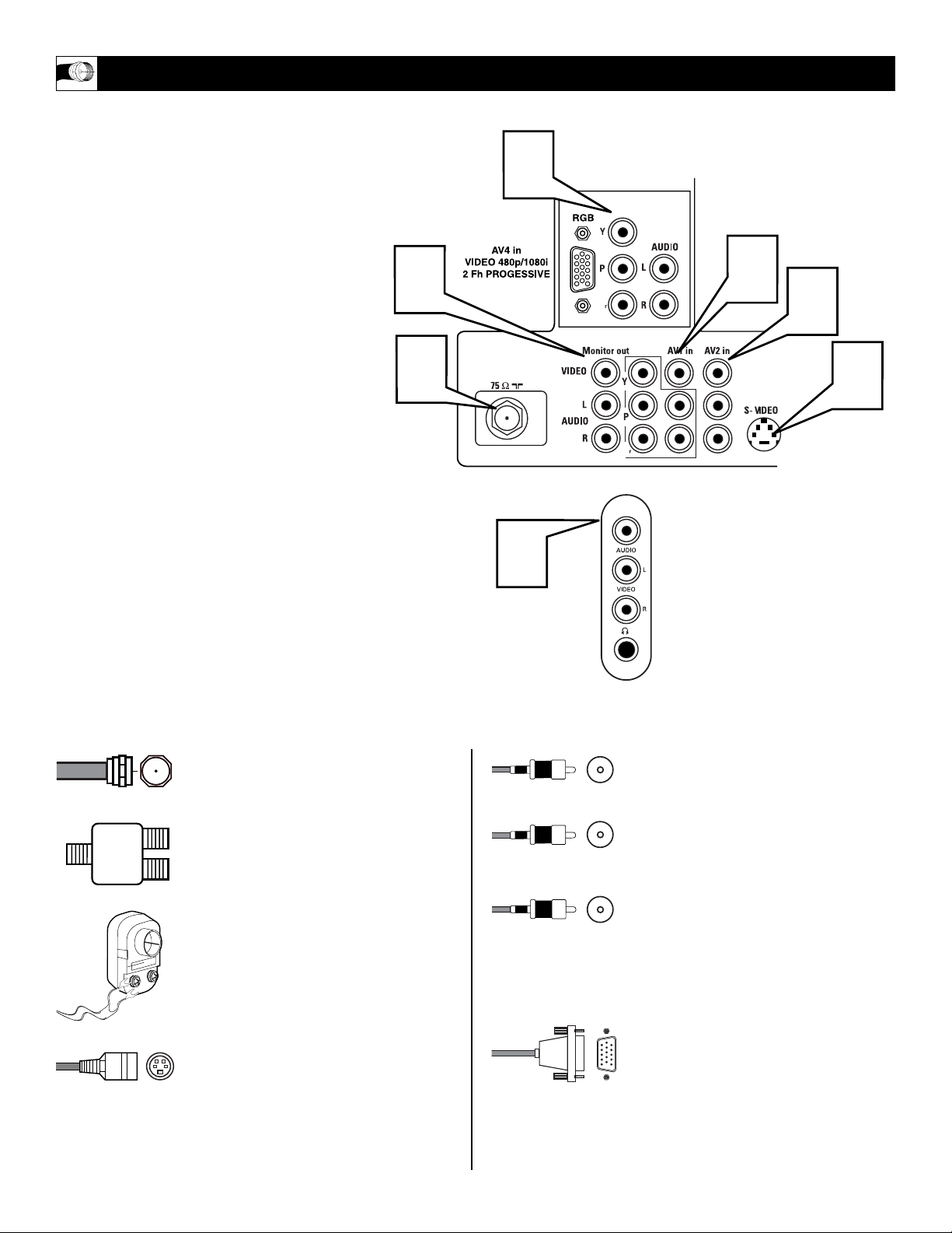
T
he television is equipped with external
input and output jacks for use with optional
accessory devices such as VCRs, DVD Player,
Gaming Units, Video Cameras, etc. The following gives a brief explanation of the different
types of jacks available and the type of cables
needed to make connections.
1
75Ω RF - Cable/Antenna Input connection jack. Located on the back of the television.
2
AV 1 in - Audio/Video connection jacks.
Located on the back of the television.
Along with Component Video Inputs.
3
AV 2 in - Audio/Video Input connection
jacks. Located on the back of the television.
4
S-Video Input jack - Used with the AV
2 in Audio Left and Right Input jacks.
Located on the back of the television.
5
Monitor Out - Audio/Video Output
connection jacks. Located on the back of
the television.
6
AV 4 in - Component Video, VGA
(RGB), and Audio Input connection
jacks. Located on the back of the television.
7
SIDE (AV 3) - Audio/Video Input jacks,
plus a Headphone jack located on the
side of the cabinet.
JACK PANEL DESCRIPTIONS AND REQUIRED CABLES
A 75-ohm coaxial cable connects signals
from an antenna or a cable TV company
to the antenna jack on the back of the TV.
Coaxial cables use “F” connectors.
A two-way signal splitter enables you to
take a single antenna or cable TV signal
and supply it to two different inputs.
A 300- to 75-ohm twin-lead adapter
accepts the antenna cables (called twinlead wires) from an antenna, allowing you
to connect the antenna signal to the TV.
An S-Video cable provides better picture
performance than regular (composite)
video connections.
S-Video cables can be used only with SVideo-compatible accessory devices. You
must also connect the left and right audio
cables to the AV 2 Audio in jacks because
the S-Video jack carries only the picture
signal, not the sound.
Video and audio cables with standard
RCA (phono) connectors connect the
video and audio jacks of accessory
devices such as VCRs and DVD players
to the jacks on the TV.
These connectors are usually color coded.
The jacks on your TV are also color
coded to match the colors of the connectors. Yellow for video (composite) and
Red and White for the right and left audio
channels. The video cables used to connect component video or RGB (high-resolution) jacks are color coded red, green,
and blue.
An VGA (HD15) cable makes a VGA
(RGB) connection to the HD INPUT-AV
4 jack on the rear of the TV.
Cable Descriptions:
Yellow - Video
White - Audio Left
Red - Audio Right
5
1
6
7
Located on the back of the TV
b
2
P
3
4
b
P
Located on the
side of the TV
Page 7
7
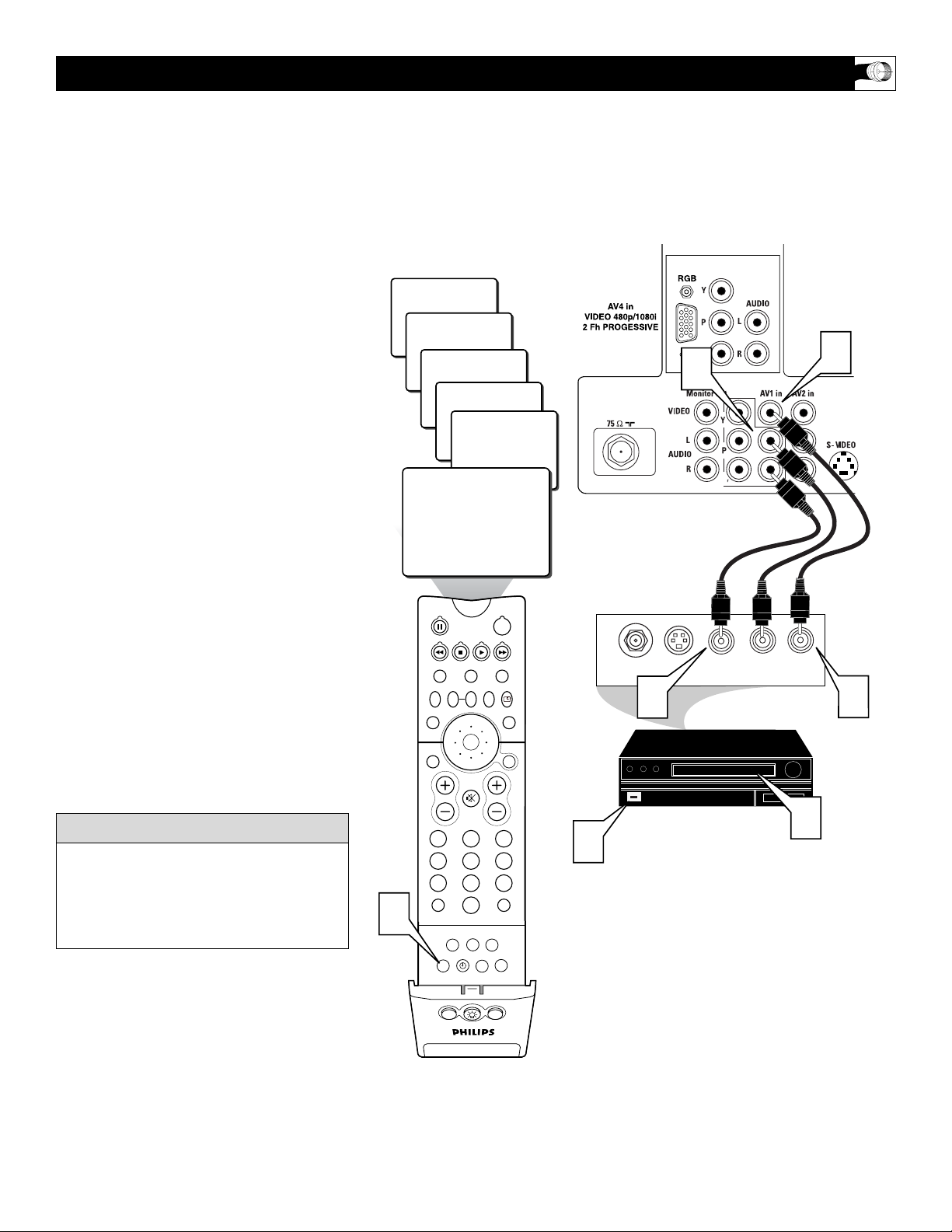
T
he TV’s audio/video input jacks are for
direct picture and sound connections
between the TV and a VCR (or similar device)
that has audio/video output jacks. Follow the
easy steps below to connect your accessory
device to the AV 1 Input Jacks located on the
back of the TV.
1
Connect the VIDEO (yellow) cable to
the VIDEO AV1 in jack on the back of
the TV.
2
Connect the AUDIO (red and white)
cables to the AUDIO (left and right)
AV1 in jacks on the rear of the TV.
3
Connect the VIDEO (yellow) cable to
the VIDEO OUT jack on the back of
the VCR.
4
Connect the AUDIO (red and white)
cables to the AUDIO (left and right)
OUT jacks on the rear of the VCR.
5
Turn the VCR (accessory device) and
the TV ON.
6
Press the AV button on the remote
control to select the AV1 channel. AV1
will appear in the upper left corner on
the TV screen.
7
With the VCR (or accessory device)
ON and a prerecorded tape (CD, DVD,
etc.) inserted, press the PLAY button
to view the tape on the television.
USING THE AV 1 INPUT JACKS
Repeatedly pressing the AV button on the
remote control will toggle the picture source
from the current channel, then AV1, CVI,
AV2, SIDE (AV3), and the AV4 Input Jack
connections.
cc
C
HECK IT OUT
AUDIO IN
(RED/WHITE)
VCR
(EQUIPPED WITH VIDEO AND
AUDIO OUTPUT JACKS)
VIDEO IN
(YELLOW)
BACK OF VCR
NOTE: Repeatedly pressing the AV button on the remote control will toggle the
picture source from the current channel, the AV1 channel, then the CVI channel,
then the AV2 channel, then the SIDE (AV3) channel and the AV4 channel. After the
AV4 channel, the AV button will select the current channel again.
BACK OF TV
24
AV4
SIDE
b
P
1
2
AV2
CVI
b
AV1
TV
SWAP PIP CH
SOUND
STATUS/
EXIT
VOL
POWER
ACC
VCR
ACTIVE
CONTROL
DN
FREEZE
UP
PICTURE
MENU/
SELECT
MUTE
CH
ANT/CABLE
OUT
4
S-VIDEO
OUT
P
R L
AUDIO OUT
VIDEO
OUT
3
6
213
546
879
TV/VCR
A/CH
0
PIP ON/OFF
SURF
REC •
CC
SAP
ITR/
HOME
HOME
RECORD
VIDEO
MOVIES
5
SURF
SLEEP
PROG.LISTDOLBY VAV
PERSONAL
PIPPOSITION
7
Page 8

AUDIO IN
(RED/WHITE)
SECOND VCR
or ACCESSORY DEVICE
(EQUIPPED WITH VIDEO
AND AUDIO OUTPUT JACKS)
VIDEO IN
(YELLOW)
BACK OF 2ND VCR
BACK OF TV
8
T
he TV’s audio/video input jacks allow you
connect multiple accessory devices at one
time to different sets of input jacks Follow the
easy steps below to connect an additional
accessory device to the AV 2 Input Jacks located on the back of the TV.
1
Connect the VIDEO (yellow) cable to
the VIDEO AV2 in jack on the back of
the TV.
2
Connect the AUDIO (red and white)
cables to the AUDIO (left and right)
AV2 in jacks on the rear of the TV.
3
Connect the VIDEO (yellow) cable to
the VIDEO OUT jack on the back of
the VCR.
4
Connect the AUDIO (red and white)
cables to the AUDIO (left and right)
OUT jacks on the rear of the VCR.
5
Turn the VCR (accessory device) and
the TV ON.
6
Press the AV button on the remote
control to select the AV2 channel. AV2
will appear in the upper left corner on
the TV screen.
7
With the VCR (or accessory device)
ON and a prerecorded tape (CD, DVD,
etc.) inserted, press the PLAY button
to view the tape on the television.
USING THE AV 2 INPUT JACKS
NOTE: Repeatedly pressing the AV button on the remote control will toggle the
picture source from the current channel, the AV1 channel, then the CVI channel,
then the AV2 channel, then the SIDE (AV3) channel and the AV4 channel. After the
AV4 channel, the AV button will select the current channel again.
FIRST VCR
CONNECTED TO AV1 INPUTS
CVI
AV1
24
AV4
SIDE
AV2
b
P
1
2
b
P
6
SWAP PIP CH
SOUND
STATUS/
EXIT
VOL
TV/VCR
A/CH
ITR/
RECORD
TV
VCR
ACTIVE
CONTROL
DN
UP
MUTE
213
546
879
0
PIP ON/OFF
SURF
REC •
SLEEP
CC
SAP
PROG.LISTDOLBY VAV
HOME
HOME
VIDEO
MOVIES
PIPPOSITION
POWER
ACC
SURF
PERSONAL
FREEZE
PICTURE
MENU/
SELECT
CH
4
3
5
7
Page 9
9
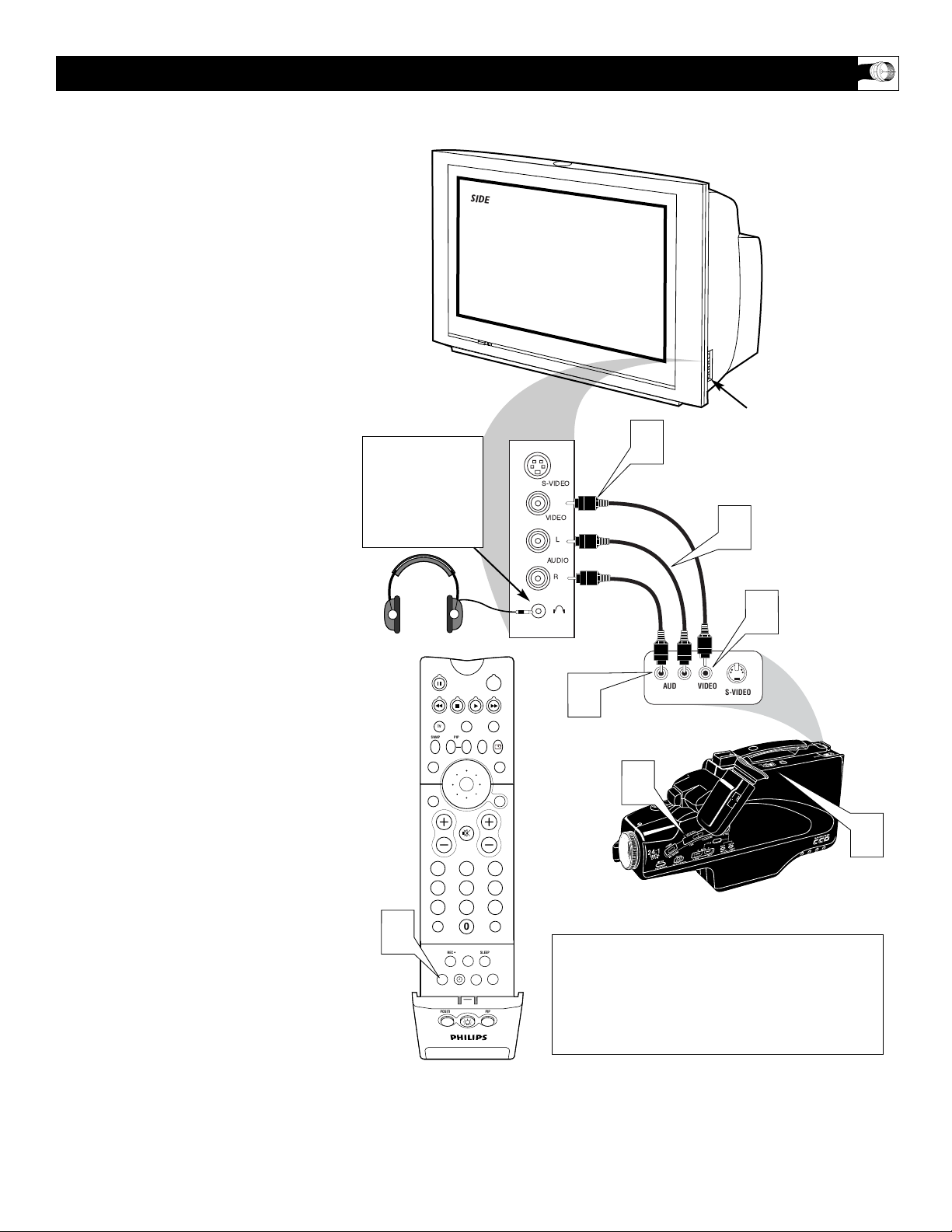
T
his television has input jacks conveniently
located on the side of the cabinet. These
jack are for easy hook-ups (without having to
move around to the back of the TV) for cameras, gaming units, and other accessory
devices that wouldn’t be connected permanently. Follow the easy steps below to connect
your accessory device to the SIDE (AV 3) Input
Jacks located on the right side of the TV.
1
Connect the VIDEO (yellow) cable to
the VIDEO in jack on the side of the
TV.
2
Connect the AUDIO (red and white)
cables to the AUDIO (left and right) in
jacks on the side of the TV.
3
Connect the VIDEO (yellow) cable to
the VIDEO OUT jack on the back of
the camera (or accessory device).
4
Connect the AUDIO (red and white)
cables to the AUDIO (left and right)
OUT jacks on the rear of the camera
(or accessory device).
5
Turn the camera (or accessory
device) and the TV ON.
6
Press the AV button on the remote
control to select the SIDE channel.
SIDE will appear in the upper left corner on the TV screen.
7
With the camera (or accessory device)
ON and a prerecorded tape (CD, DVD,
Game Card, etc., depending on type of
accessory device) inserted, press the
PLAY button to view the tape on the
television.
USING THE SIDE (AV 3) INPUT JACKS
VIDEO IN
(YELLOW)
NOTE: The S-Video Cable can be used in place of
the Yellow Video cable shown in this diagram. If
your camera or accessory device has a S-Video
output jack, connecting the video signal through
the S-Video jack will reproduce the video signal
with greater quality.
AUDIO IN
(RED/WHITE)
Jack Panel of Camera
or External Accessory
Device
SIDE (AV 3) Input Jacks
Located on the Side of
the Television Cabinet
The SIDE JACKS also
contain a HEADPHONE
JACK. When headphones
are plugged into this
jack, the sound coming
from the TV is muted
and can only be heard
through the headphones.
TV
VCR
SWAP PIP CH
DN
UP
SOUND
STATUS/
EXIT
MUTE
VOL
213
546
879
TV/VCR
A/CH
0
6
RECORD
SURF
REC •
CC
SAP
ITR/
HOME
VIDEO
SIDE
ACTIVE
CONTROL
PIP ON/OFF
HOME
MOVIES
1
S-VIDEO
VIDEO
L
AUDIO
R
POWER
4
ACC
FREEZE
PICTURE
MENU/
SELECT
CH
7
LEFT RIGHT
VIDEOAUDIO
2
3
S-VIDEO
5
SURF
SLEEP
PROG.LISTDOLBY VAV
PERSONAL
PIPPOSITION
Page 10
10
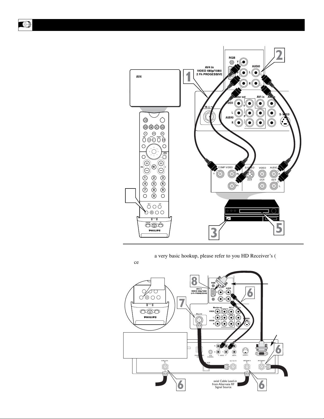
T
he AV4 Input Jacks provide Both Component
and VGA Video Inputs at 1080i, for accessory like HD Receiver and Digital DVD Players.
Using the color difference signals (Pb, Pr) and
the luminance (Y) signal will improve color
bandwidth information. The TV can also become
a monitor for projectors, computers or HD
Receivers using the VGA Input.
Connecting a Digital device using the COMPONENT VIDEO Inputs:
1
Connect the Component (Y, Pb, Pr)
Video OUT jacks from the DVD player
(or similar device) to the (Y, Pb, Pr) AV4
in(put) jacks on the TV.
2
Connect the red and white AUDIO
CABLES to the Audio (left and right)
output jacks on the rear of the accessory
device to the Audio (L and R) AV4
in(put) jacks on the TV.
3
Turn the TV and the DVD (or digital
accessory device) ON.
4
Press the AV button on the remote to
tune to the AV4 channel.
5
Press the PLAY button on the DVD (or
digital accessory device) to view the program on the television.
Connect an HD Reviver to the VGA Input:
Please refer to your Receiver’s Owner’s Manual
for more detailed hookup options.
6
If using a Satellite Dish, Cable signal or
Antenna signal, connect the 75Ω round
cable from a Satellite Dish to the SATELLITE IN and/or the Cable and Antenna
signals to the ANTENNA “A” or “B” IN
on the back of the HD Receiver.
7
Connect another 75Ω round cable from
the OUT TO TV jack on the HD Receiver
to the 75Ω IN on the back of the TV.
8
Connect a VGA cable from the VGA
OUT on the HD Receiver to the AV4
VGA Input jack on the back of the TV.
9
Connect the Audio L(eft) and R(ight)
cables from the AUDIO Outputs on the
HD Receiver to the AV4 AUDIO Inputs
on the back of the TV.
With both the HD Receiver and the television ON, Press the AV button on the
remote to tune to the AV 4 Channel and
view the video input from the VGA supplied signal.
USING THE AV 4 INPUT JACKS
10
Using the VGA Input and a HD Receiver
Note: This is a very basic hookup, please refer to you HD Receiver’s (or accessory
device’s) Owner’s Manual for detailed hookup instructions.
Using the AV4 Component Video Inputs
JACK PANEL
ON BACK OF TV
JACK PANEL
ON BACK OF TV
JACK PANEL
OF DIGITAL DEVICE
SUCH AS A DVD PLAYER
JACK PANEL
OF HD RECEIVER
WITH VGA OUT
When using the AV4 channel (inputs),
some controls and features will not be
accessible for adjustment. SHARPNESS,
TINT, DYNAMIC CONTRAST, and the
FORMAT Controls will not be available.
Note: If the AV4 channel is tuned
and no signal connection present,
the screen could jump or flash.
AUDIO IN
(RED/WHITE)
COMPONENT
VIDEO
CABLES
AV4
POWER
ACC
VCR
ACTIVE
CONTROL
FREEZE
DN
UP
PICTURE
MENU/
SELECT
MUTE
CH
213
546
879
SURF
0
PIP ON/OFF
SURF
REC •
SLEEP
CC
SAP
PROG.LISTDOLBY VAV
HOME
HOME
PERSONAL
VIDEO
MOVIES
PIPPOSITION
4
SWAP PIP CH
SOUND
STATUS/
EXIT
VOL
TV/VCR
A/CH
RECORD
TV
ITR/
1
3
b
P
b
P
2
5
PIP ON/OFFSURF
10
REC •
SLEEP
CC
SAP
PROG.LISTDOLBY VAV
ITR/
HOME
HOME
RECORD
Coaxial Cable
Lead-in from
Satellite Dish
PERSONAL
VIDEO
MOVIES
PIPPOSITION
SATELLITE
7
ACCESS CARD
IN
8
DIGITALAUDIO
OUTPUT
PHONE JACK
b
P
b
P
L
R
L
R
VCR
CONTROL
Coaxial Cable Lead-in
from Alternate RF
Signal Source
VIDEOAUDIO
OUTTO TV
6
S-VIDEO
ANTENNABINANTENNAA
66
6
IN
Coaxial Cable
Lead-in from Cable Outlet,
Converter Box,
or VHF/UHF Antenna
Page 11
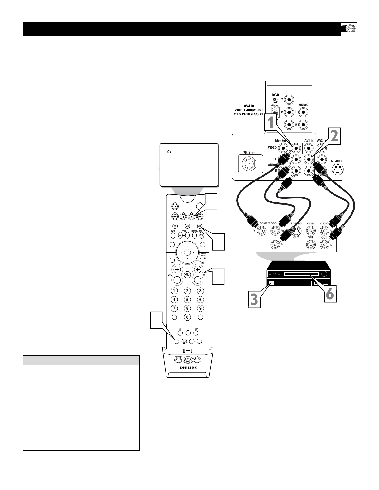
C
omponent Video inputs provide for the
highest possible color and picture resolution in the playback of digital signal source
material, such as with DVD players. The
color difference signals (Pb, Pr) and the luminance (Y) signal are connected and received
separately, which allows for improved color
bandwidth information (not possible when
using composite video or S-Video connections).
1
Connect the Component (Y, Pb, Pr)
Video OUT jacks from the DVD play-
er (or similar device) to the (Y, Pb, Pr)
in(put) jacks on the TV. When using
the Component Video Inputs, it is best
not to connect a signal to the AV1
Video Input.
2
Connect the red and white AUDIO
CABLES to the Audio (left and right)
output jacks on the rear of the accessory device to the Audio (L and R) AV1
in(put) jacks on the TV.
3
Turn the TV and the DVD (or digital
accessory device) ON.
4
Press the AV button or the CH +, –
buttons to scroll the available channels
until CVI appears in the upper left corner of the TV screen.
5
Slide the TV/VCR/ACC Switch to
the ACC position.
NOTE: The remote control may have
to be programmed to operate your
accessory device. Please refer to the
Using the Remote control with
Accessory Devices section starting on
page 46.
6
Insert a DVD disc into the DVD player
and press the PLAY button on the
remote.
11
USING THE COMPONENT VIDEO INPUT (CVI) JACKS
The description for the component video
connectors may differ depending on the
DVD player or accessory digital source
equipment used (for example, Y, Pb, Pr; Y,
B-Y, R-Y; Y, Cr, Cb). Although abbreviations and terms may vary, the letters b and r
stand for the blue and red color component
signal connectors, and Y indicates the luminance signal. Refer to your DVD or digital
accessory owner’s manual for definitions
and connection details.
HELPFUL HINT
AUDIO IN
(RED/WHITE)
COMPONENT
VIDEO
CABLES
BACK OF TV
ACCESSORY DEVICE
EQUIPPED WITH CONPO-
NENT VIDEO OUTPUTS.
The CVI connection will be dominate
over the AV1 Video Input. When a
Component Video Device is connected
as described, it is best not to have a
video signal connected to the AV1
Video Input jack.
CVI
POWER
6
TV
SWAP PIP CH
SOUND
DN
ACC
VCR
ACTIVE
CONTROL
FREEZE
UP
PICTURE
5
STATUS/
EXIT
SELECT
MENU/
1
b
P
b
P
2
4
VOL
TV/VCR
A/CH
SURF
REC •
SAP
ITR/
HOME
RECORD
VIDEO
MUTE
CH
4
213
546
879
SURF
0
PIP ON/OFF
SLEEP
CC
PROG.LISTDOLBY VAV
HOME
PERSONAL
MOVIES
PIPPOSITION
3
6
Page 12

12
T
he S(uper)-Video connection on the rear
of the TV can provide you with better picture detail and clarity for the playback of
accessory sources such as DBS (digital
broadcast satellite), DVD (digital video
discs), video games, and S-VHS VCR (video
cassette recorder) tapes than the normal
antenna picture connections.
NOTE: The accessory device must have an
S-VIDEO OUT(put) jack in order for you to
complete the connection on this page.
1
Connect the S-VIDEO CABLE to the
S-VIDEO input jack on the rear of the
television.
2
Connect the AUDIO (red and white)
cables to the AUDIO AV2 in jacks on
the rear of the TV
.
3
Connect the S-VIDEO CABLE to the
S-VIDEO output jack on the accessory
device.
4
Connect the red and white AUDIO
cables to the AUDIO (left and right)
output jacks on the rear of the accessory device.
5
Turn the VCR, DVD or other accessory device ON.
6
Press the AV button on the remote
control to select the AV2 channel. AV2
will appear in the upper left corner on
the TV screen.
7
With the VCR (or accessory device)
ON and a prerecorded tape inserted,
press the PLAY button to view the
tape on the television.
USING THE S-VIDEO INPUT JACKS
The S-Video jack and the AV 2 jacks work
together. When a device is connected to the
S-Video jack, do not connect a signal to the
AV 2 in Video jack. This could cause an
over-lapping of two video images on the TV
screen.
cc
C
HECK IT OUT
JACK PANEL
ON BACK OF TV
AUDIO CABLES
(Red & White)
S-VIDEO CABLE
(Red & White)
VCR or EXTERNAL
ACCESSORY DEVICE
WITH S-VIDEO OUTPUT
When using the S-Video
Input, do not connect an
video signal to the AV 2
in Video Jack. This could
cause a ghost image to
appear over the S-Video
signal.
CVI
AV1
24
AV4
SIDE
AV2
b
P
2
b
P
1
6
TV
SWAP PIP CH
SOUND
STATUS/
EXIT
VOL
TV/VCR
A/CH
ITR/
RECORD
DN
SURF
REC •
SAP
HOME
VIDEO
POWER
ACC
VCR
ACTIVE
CONTROL
FREEZE
UP
PICTURE
MENU/
SELECT
MUTE
CH
213
546
879
SURF
0
PIP ON/OFF
SLEEP
CC
PROG.LISTDOLBY VAV
HOME
PERSONAL
MOVIES
PIPPOSITION
4
5
7
3
Page 13
13
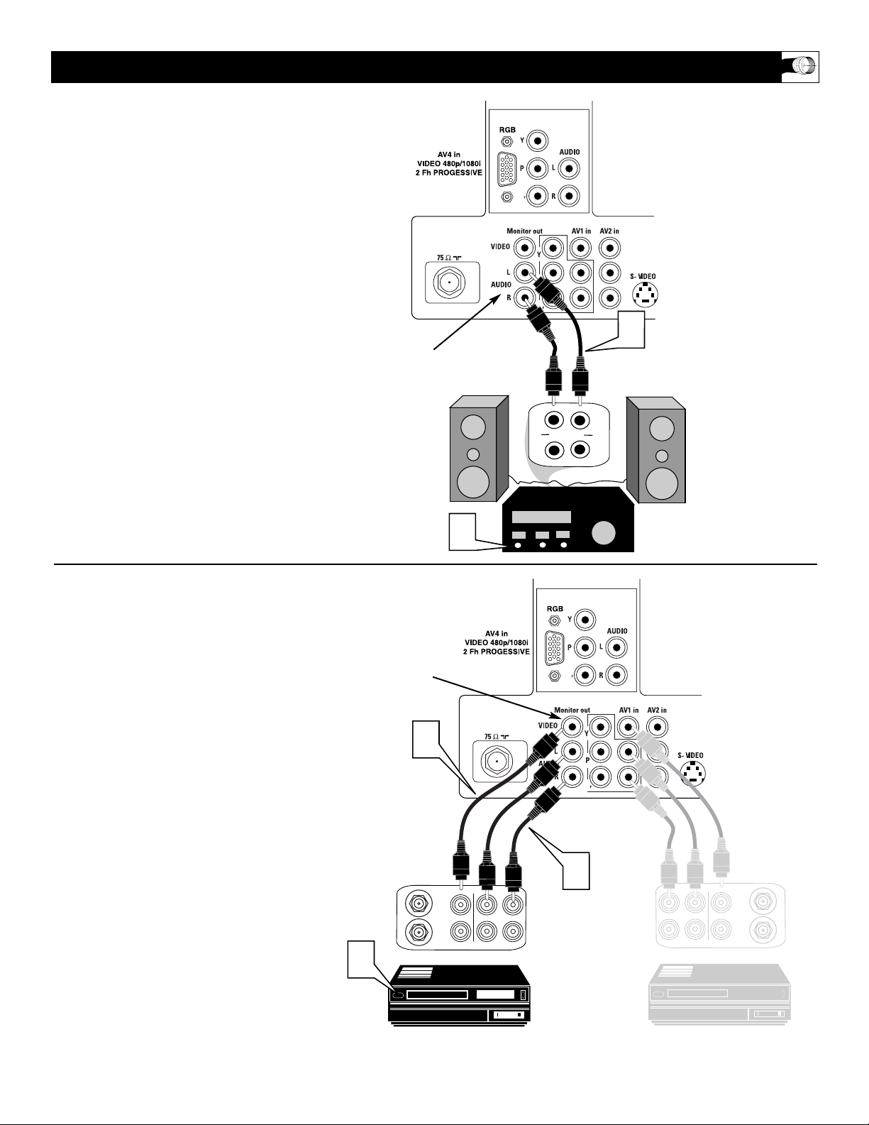
T
he Audio/Video (Monitor) Output jacks
are great for recording with a VCR or
used to connect an external audio system for
better sound reproduction.
For Audio System Connection:
1
Connect one end of the R(ight) and
L(eft) AUDIO (Monitor Out) jacks on
the TV to the R and L audio input jacks
on your amplifier or sound system. Set
the audio system’s volume to a normal
listening level.
NOTE: Refer to page 21 to set the TV’s Audio
Out Control to VARIABLE if you want to control the volume of the audio system with the
TV remote control. (Set the control to FIXED
if you want to control the volume from the
audio system.)
2
Turn the TV and audio system ON.
You can now adjust the sound level
coming from the audio system with the
VOLUME (+) or (–) button on the TV
or remote control.
For Second VCR Connection:
NOTE: Refer to page 7 for the proper
hookup of the first VCR. Follow the instructions on how to tune to the AV 1 channel to
view a pre-recorded tape.
The following steps allow you to connect a
second VCR to record the program while
your watching it.
3
Connect one end of the yellow Video
Cable to the Monitor Out VIDEO
plug. Connect the other end to the
VIDEO IN plug on the second VCR.
4
Connect one end of the red and white
Audio cable from the Monitor Out
AUDIO L and R plugs on the TV to the
AUDIO IN plugs on the VCR.
5
Turn the Second VCR ON, insert a
black VHS tape and it’s ready to record
what’s being viewed on the TV screen.
USING THE MONITOR OUTPUT JACKS
JACK PANEL
Located on the
back of the TV
AUDIO CABLES
(Red & White)
AUDIO SYSTEM
with AUDIO
INPUTS
MONITOR OUT
AUDIO L(eft) and R(ight)
JACK PANEL
Located on the
back of the TV
AUDIO CABLES
(Red & White)
FIRST VCR (accessory device)
(Hookup from Page 7)
MONITOR OUT
VIDEO &
AUDIO L(eft) and R(ight)
SECOND VCR
VIDEO CABLE
(Yellow)
b
P
b
P
3
ANTENNA
ANTENNA
OUT
5
IN
2
OUT OUT
VIDEO
IN
RL
AUDIO
IN
R
L
T
U
P
IN
V
/T
X
U
A
T
U
P
IN
O
N
O
H
P
b
P
b
P
4
1
LR
AUDIO
IN
ANTENNA
OUTOUT
IN
VIDEO
ANTENNA
OUT
IN
Page 14

14
T
o adjust your TV picture controls, select a
channel and follow these steps.
1
Press the MENU/SELECT button on
the remote control to show the onscreen
menu. PICTURE will be highlighted.
2
Press the CURSOR RING RIGHT and
the menu will shift to the left. BRIGHTNESS will be highlighted and an adjustment bar will be shown to the right.
3
Use the CURSOR RING LEFT or
RIGHT to adjust the BRIGHTNESS level
of the picture.
4
After adjusting the BRIGHTNESS control, press the CURSOR RING DOWN
to select another picture adjustment:
COLOR, PICTURE, SHARPNESS,
TINT, OR COLOR TEMP. Press the
CURSOR RING LEFT or RIGHT to
adjust the selected control.
NOTE: The menu will show only five items at a
time, so you will need to continue scrolling with
the CURSOR RING DOWN to adjust the TINT
and COLOR TEMP.
5
Press the STATUS/EXIT button to
remove the menu from the screen.
ADJUSTING THE PICTURE CONTROLS
Remember, when the bar scale is centered
, the control settings are at
normal, mid-range levels. Picture adjustments are described here.
NOTE: The SHARPNESS and TINT
Controls will not be available for adjustments when tuned to the AV4 Inputs (AV4
Channel) and CVI Inputs (CVI Channel).
BRIGHTNESS – adds or subtracts light
from the darkest part of the picture.
COLOR – adds or eliminates color.
PICTURE – improves the detail of the light-
est parts of the picture.
SHARPNESS – improves the detail in the
picture.
TINT – adjusts the picture to obtain natural
skin tones.
COLOR TEMP offers NORMAL, COOL, or
WARM picture preferences.
NORMAL – keeps whites, white.
COOL – makes whites, bluish.
WARM – makes whites, reddish.
HELPFUL HINT
1
PICTURE
SOUND
FEATURES
INSTALL
TV
SWAP PIP CH
SOUND
STATUS/
EXIT
VOL
4
TV/VCR
A/CH
ITR/
RECORD
BRIGHTNESS
COLOR
PICTURE
SHARPNESS
TINT
POWER
ACC
VCR
ACTIVE
CONTROL
DN
SURF
REC •
SAP
HOME
VIDEO
FREEZE
UP
PICTURE
MENU/
SELECT
MUTE
213
546
879
0
CH
SURF
PIP ON/OFF
SLEEP
CC
PROG.LISTDOLBY VAV
HOME
PERSONAL
MOVIES
PIPPOSITION
2,3
5
PICTURE
BRIGHTNESS 30
COLOR
PICTURE
SHARPNESS
TINT
PICTURE
BRIGHTNESS
COLOR 30
PICTURE
SHARPNESS
TINT
PICTURE
BRIGHTNESS
COLOR
PICTURE 30
SHARPNESS
TINT
PICTURE
BRIGHTNESS
COLOR
PICTURE
SHARPNESS 30
TINT
PICTURE
BRIGHTNESS
COLOR
PICTURE
SHARPNESS
TINT 0
PICTURE
COLOR
PICTURE
SHARPNESS
TINT
COLOR TEMP NORMAL
OR
COLOR TEMP WARM
OR
COLOR TEMP COOL
Page 15

15
T
he Digital Options (Eye Fidelity) control
gives you a choice between two different
picture scanning modes: Progressive Scan
and Interlaced (1050i).
Progressive Scan doubles the number of picture lines, eliminating line flicker and providing a jitter-free picture.
Interlaced (1050i mode) improves the appearance of onscreen motion. All ‘Picture
Adjustment Controls’ stay controllable,
including the Active Control. It also helps
smooth out jagged lines that are sometimes
seen on curved and angled surfaces in the
picture.
1
Press the MENU/SELECT button on
the remote to show the onscreen menu.
PICTURE will be highlighted.
2
Press the CURSOR RING RIGHT and
the menu will shift to the left. BRIGHTNESS will be highlighted and an adjustment bar will be shown to the right.
3
Press the CURSOR RING DOWN
repeatedly until the Digital Options
control is highlighted.
4
Press the CURSOR RING RIGHT
or LEFT until you select the option
you want, either PROGRESSIVE or
1050i.
5
Press the STATUS/EXIT button to
remove the menu from the screen.
HOW TO USE THE DIGITAL OPTIONS CONTROL
The Digital Options (Eye Fidelity) Control
is not available for use with the AV 4 input
jacks.
HELPFUL HINT
PICTURE
SOUND
FEATURES
INSTALL
BRIGHTNESS
COLOR
PICTURE
SHARPNESS
TINT
PICTURE
BRIGHTNESS 30
COLOR
PICTURE
SHARPNESS
TINT
5
4
SWAP PIP CH
SOUND
STATUS/
EXIT
VOL
3
TV/VCR
A/CH
ITR/
RECORD
POWER
TV
VCR
ACTIVE
CONTROL
DN
UP
MUTE
213
546
879
0
PIP ON/OFF
SURF
REC •
SLEEP
CC
SAP
HOME
VIDEO
HOME
MOVIES
PROG.LISTDOLBY VAV
PERSONAL
PIPPOSITION
ACC
FREEZE
PICTURE
SURF
MENU/
SELECT
2,4
CH
PICTURE
PICTURE
SHARPNESS
TINT
COLOR TEMP
DIGITAL OPTIONS PROGRESSIVE
OR
DIGITAL OPTIONS 1050i LINES
1
Page 16

16
T
he Dynamic Contrast control allows you
to sharpen the picture quality by making
dark portions of the picture darker and light
portions of the picture more noticeable.
Normally, you will probably want to select
MED. In certain circumstances, however, you
may prefer MIN or MAX.
1
Press the MENU/SELECT button on
the remote to show the onscreen menu.
PICTURE will be highlighted.
2
Press the CURSOR RING RIGHT and
the menu will shift to the left. BRIGHTNESS will be highlighted and an adjustment bar will be shown to the right.
3
Press the CURSOR RING DOWN
repeatedly until the DYN. CONTRAST control is highlighted.
4
Press the CURSOR RING RIGHT
or LEFT until you select the option
you want, either OFF, MIN, MED, or
MAX.
5
Press the STATUS/EXIT button to
remove the menu from the screen.
HOW TO SET THE DYNAMIC CONTRAST CONTROL
The Dynamic Contrast control is not available for use with the AV 4 Inputs (AV4
Channel).
HELPFUL
HINT
5
4
PICTURE
SOUND
FEATURES
INSTALL
TV
SWAP PIP CH
SOUND
STATUS/
EXIT
VOL
3
BRIGHTNESS
COLOR
PICTURE
SHARPNESS
TINT
POWER
ACC
VCR
ACTIVE
CONTROL
DN
FREEZE
UP
MUTE
213
PICTURE
MENU/
SELECT
CH
2,4
1
PICTURE
BRIGHTNESS 30
COLOR
PICTURE
SHARPNESS
TINT
PICTURE
SHARPNESS
TINT
COLOR TEMP
DIGITAL OPTIONS
DYN. CONTRAST OFF
OR
DYN. CONTRAST MIN
OR
DYN. CONTRAST MED
OR
DYN. CONTRAST MAX
546
879
TV/VCR
A/CH
0
PIP ON/OFF
SURF
REC •
CC
SAP
ITR/
HOME
VIDEO
HOME
MOVIES
RECORD
SURF
SLEEP
PROG.LISTDOLBY VAV
PERSONAL
PIPPOSITION
Page 17
17
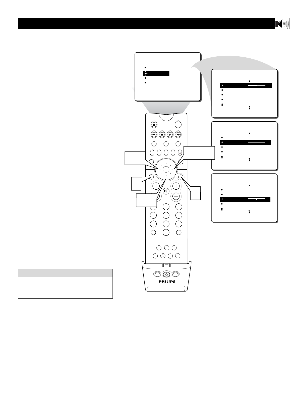
B
esides the normal volume level control,
your TV also has individual sound-adjustment controls. The TREBLE (high frequency), BASS (low frequency), and Speaker BALANCE may all be used to adjust the sound
playback of TV programs.
1
Press the MENU/SELECT button on
the remote control to show the
onscreen menu.
2
Press the CURSOR RING DOWN
once to highlight SOUND.
3
Press the CURSOR RING RIGHT
and the menu will shift to the left.
TREBLE will be highlighted and an
adjustment bar will be shown to the
right.
4
Use the CURSOR RING RIGHT or
LEFT to adjust the TREBLE (high fre-
quency) level of the television’s sound.
5
After adjusting the TREBLE control,
press the CURSOR RING DOWN to
select another sound adjustment:
BASS or BALANCE.
6
Press the CURSOR RING RIGHT
or LEFT to adjust the selected control.
7
Press the STATUS/EXIT button to
remove the menu from the screen.
ADJUSTING THE TREBLE, BASS, AND BALANCE CONTROLS
Remember, when the bar scale is centered,
speaker BALANCE is centered between the
TV’s left and right side speakers.
HELPFUL HINT
4,6
7
2,5
PICTURE
SOUND
FEATURES
INSTALL
TV
SWAP PIP CH
SOUND
STATUS/
EXIT
VOL
TV/VCR
A/CH
ITR/
RECORD
TREBLE
BASS
BALANCE
AVL
INCR. SURROUND
POWER
ACC
VCR
ACTIVE
CONTROL
DN
SURF
REC •
SAP
HOME
VIDEO
FREEZE
UP
PICTURE
MENU/
SELECT
MUTE
CH
213
546
879
SURF
0
PIP ON/OFF
SLEEP
CC
PROG.LISTDOLBY VAV
HOME
PERSONAL
MOVIES
PIPPOSITION
3,4,6
1
SOUND
TREBLE 30
BASS
BALANCE
AVL
INCR. SURROUND
SOUND
TREBLE
BASS 30
BALANCE
AVL
INCR. SURROUND
SOUND
TREBLE
BASS
BALANCE 0
AVL
INCR. SURROUND
Page 18

18
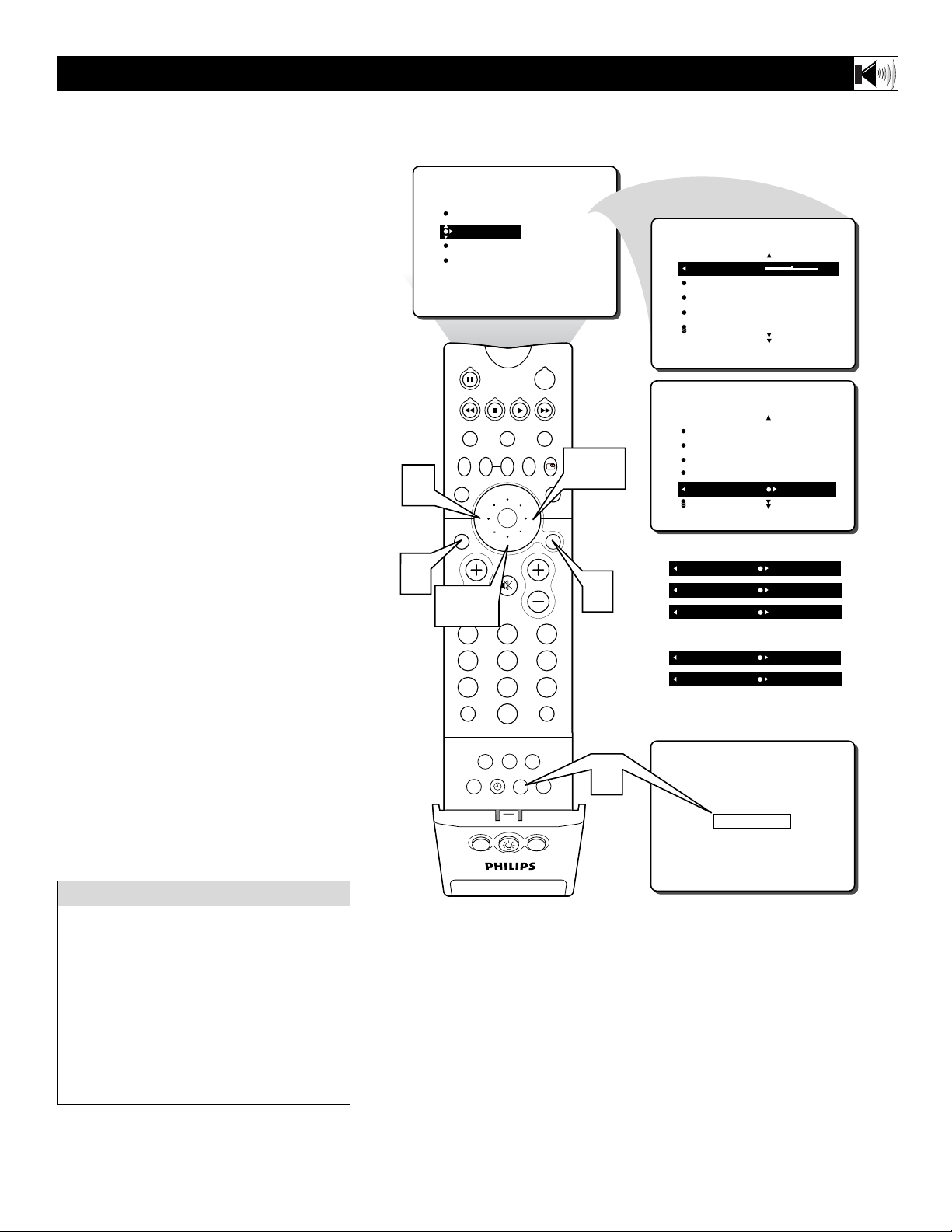
I
n most cases, the volume levels coming
from broadcast programming or commercials are never the same. With the AVL
(Audio Volume Leveler) control turned ON,
you can have the TV level out sound that is
being heard. This makes for a more consistent sound by reducing the peaks and valleys
that occur during program changes or commercial breaks. To turn the AVL ON, follow
these steps.
1
Press the MENU/SELECT button on
the remote control to show the
onscreen menu.
2
Press the CURSOR RING DOWN
once to highlight SOUND.
3
Press the CURSOR RING RIGHT
and the menu will shift to the left.
TREBLE will be highlighted and an
adjustment bar will be shown to the
right.
4
Press the CURSOR RING DOWN
repeatedly until AVL is highlighted.
5
Press the CURSOR RING RIGHT
or LEFT to toggle AVL ON or OFF.
6
Press the STATUS/EXIT button to
remove the menu from the screen.
HOW TO USE THE AVL CONTROL
5
6
PICTURE
SOUND
FEATURES
INSTALL
TV
SWAP PIP CH
DN
SOUND
STATUS/
EXIT
VOL
2,4
TV/VCR
A/CH
TREBLE
BASS
BALANCE
AVL
INCR. SURROUND
POWER
ACC
VCR
ACTIVE
CONTROL
FREEZE
UP
MUTE
PICTURE
MENU/
SELECT
3,5
CH
1
213
546
879
SURF
0
SOUND
TREBLE 30
BASS
BALANCE
AVL
INCR. SURROUND
SOUND
TREBLE
BASS
BALANCE
AVL ON
INCR. SURROUND
OR
SOUND
TREBLE
BASS
BALANCE
AVL OFF
INCR. SURROUND
ITR/
RECORD
PIP ON/OFF
SURF
REC •
SLEEP
CC
SAP
HOME
VIDEO
HOME
MOVIES
PROG.LISTDOLBY VAV
PERSONAL
PIPPOSITION
Page 19
19
T
he Incredible Surround feature adds
greater depth and dimension to both monaural (MONO) and stereo TV sound. With
the control set to INCR. SURROUND
(Incredible Surround), the TV’s speakers can
add even wider sound separation to normal
broadcasts.
1
Press the MENU/SELECT button on
the remote control to show the
onscreen menu.
2
Press the CURSOR RING DOWN
once to highlight SOUND.
3
Press the CURSOR RING RIGHT
and the menu will shift to the left.
TREBLE will be highlighted and an
adjustment bar will be shown to the
right.
4
Press the CURSOR RING DOWN
repeatedly until INCR. SURROUND is
highlighted. (Incredible Surround)
5
Press the CURSOR RING RIGHT
or LEFT to toggle the INCR. SUR-
ROUND control settings.
If signal is Stereo: Select STEREO,
INCR. SURROUND, or DOLBY*
VIRTUAL.
If signal is MONO: Select MONO, or
SPATIAL.
6
Press the STATUS/EXIT button to
remove the menu from the screen.
7
You can also change the INCR. SURROUND onscreen menu control settings by pressing the VIRTUAL
DOLBY button on the remote control.
HOW TO USE THE INCREDIBLE SURROUND CONTROL
SPATIAL – widens the sound, simulating a
broader, fuller sound.
INCR. SURROUND – widens the sound,
simulating a broader, fuller sound.
DOLBY* VIRTUAL (with Virtual Dolby
Surround signals) simulates the surround-
sound experience from two speakers using
Dolby Pro Logic* providing the listener
with the sensation of being surrounded by
additional speakers.
HELPFUL HINT
*Manufactured under license from Dolby Laboratories.
“Dolby”, “Pro Logic”, and the double-D symbol are
trademarks of Dolby Laboratories.
5
6
PICTURE
SOUND
FEATURES
INSTALL
TV
SWAP PIP CH
SOUND
STATUS/
EXIT
VOL
2,4
TV/VCR
A/CH
SURF
REC •
SAP
ITR/
RECORD
TREBLE
BASS
BALANCE
AVL
INCR. SURROUND
POWER
ACC
VCR
ACTIVE
CONTROL
DN
HOME
VIDEO
FREEZE
UP
MUTE
213
546
879
0
PIP ON/OFF
CC
HOME
MOVIES
SLEEP
PROG.LISTDOLBY VAV
PERSONAL
PIPPOSITION
PICTURE
SURF
MENU/
SELECT
3,5
CH
1
7
SOUND
TREBLE 30
BASS
BALANCE
AVL
INCR. SURROUND
SOUND
TREBLE
BASS
BALANCE
AVL ON
INCR. SURROUND STEREO
If the signal is in STEREO, choose from:
INCR. SURROUND STEREO
INCR. SURROUND INCR. SURROUND
INCR. SURROUND DOLBY VIRTUAL
If the signal is in MONO, choose from:
INCR. SURROUND MONO
INCR. SURROUND SPATIAL
DOLBY VIRTUAL
Page 20

20
T
he Headphone Jack located on the side of
the television’s cabinet has independant
volume and balance controls. Using these
controls, you can set a comfortable volume
for use when a set of headphones are in use.
The headphones will also allow you to hear
the audio when the PIP feature is on.
1
Press the MENU/SELECT button on
the remote control to show the
onscreen menu.
2
Press the CURSOR RING DOWN
once to highlight SOUND.
3
Press the CURSOR RING RIGHT
and the menu will shift to the left.
TREBLE will be highlighted and an
adjustment bar will be shown to the
right.
4
Press the CURSOR RING DOWN
repeatedly until HEADPHONE is highlighted.
5
Press the CURSOR RING RIGHT to
highlight the Headphone options.
6
Press the CURSOR RING UP or
DOWN to select the VOLUME or
BALANCE Control.
7
Press the CURSOR RING LEFT or
RIGHT to ajdust either control.
8
Press the STATUS/EXIT button to
remove the menu from the screen.
HOW TO ADJUST THE HEADPHONE VOLUME AND BALANCE CONTROLS
7
8
PICTURE
SOUND
FEATURES
INSTALL
TV
6
SWAP PIP CH
SOUND
STATUS/
EXIT
VOL
2
4
TV/VCR
6
A/CH
ITR/
RECORD
TREBLE
BASS
BALANCE
AVL
INCR. SURROUND
POWER
ACC
VCR
ACTIVE
CONTROL
DN
SURF
REC •
SAP
HOME
VIDEO
FREEZE
UP
PICTURE
MENU/
SELECT
MUTE
CH
213
546
879
SURF
0
PIP ON/OFF
SLEEP
CC
PROG.LISTDOLBY VAV
HOME
PERSONAL
MOVIES
PIPPOSITION
3
5
7
1
SOUND
TREBLE 30
BASS
BALANCE
AVL
INCR. SURROUND
SOUND
BASS
BALANCE
AVL
INCR. SURROUND
HEADPHONE
SOUND
HEADPHONE
VOLUME 30
BALANCE
SOUND
HEADPHONE
VOLUME 30
BALANCE 0
VOLUME
BALANCE
OR
Page 21

21
Y
ou can receive broadcast stereo TV pro-
grams. The TV has both an amplifier and
twin speakers through which the stereo sound
can be heard.
1
Press the MENU/SELECT button on
the remote control to show the
onscreen menu.
2
Press the CURSOR RING DOWN
once to highlight SOUND.
3
Press the CURSOR RING RIGHT
and the menu will shift to the left.
TREBLE will be highlighted and an
adjustment bar will be shown to the
right.
4
Press the CURSOR RING DOWN
repeatedly until STEREO is highlighted.
5
Press the CURSOR RING RIGHT
or LEFT to select STEREO or
MONO.
6
Press the STATUS/EXIT button to
remove the menu from the screen.
HOW TO SET THE STEREO CONTROL
An SAP is an additional part of the stereo
broadcast system. Sent as a third audio
channel, an SAP can be heard apart from the
current TV program sound. TV stations are
free to use SAP for any number of purposes.
If an SAP signal is not present with a selected program, the SAP option cannot be selected. Also, if SAP is selected on a channel
(with SAP) and you select another channel,
when you return to the original channel, SAP
will be OFF. You will have to reselect the
SAP feature.
SAP-SECONDARY AUDIO PROGRAM
Remember, if stereo is not present on a
selected show and the TV is placed in the
STEREO mode, the sound coming from the
set will remain monaural.
HELPFUL HINT
6
PICTURE
SOUND
FEATURES
INSTALL
SWAP PIP CH
5
SOUND
STATUS/
EXIT
VOL
2,4
TREBLE
BASS
BALANCE
AVL
INCR. SURROUND
POWER
TV
VCR
ACTIVE
CONTROL
DN
UP
MUTE
213
546
ACC
FREEZE
PICTURE
MENU/
SELECT
CH
3,5
1
SOUND
TREBLE 30
BASS
BALANCE
AVL
INCR. SURROUND
SOUND
BALANCE
AVL
INCR. SURROUND
HEADPHONE
STEREO STEREO
OR
SOUND
BALANCE
AVL
INCR. SURROUND
HEADPHONE
STEREO MONO
879
TV/VCR
A/CH
SURF
REC •
SAP
ITR/
HOME
RECORD
VIDEO
SOUND
AVL
INCR. SURROUND
HEADPHONE
STEREO
SAP AVAILABLE
IF SECONDARY AUDIO PROGRAMING
IS BEING BROADCAST:
SAP AVAILABLE
SAP OFF
SURF
0
PIP ON/OFF
SLEEP
CC
PROG.LISTDOLBY VAV
HOME
PERSONAL
MOVIES
PIPPOSITION
OR
SOUND
AVL
INCR. SURROUND
HEADPHONE
STEREO
SAP NOT AVAILABLE
IF SECONDARY AUDIO PROGRAMING
IS NOT BEING BROADCAST:
SAP NOT AVAILABLE
OR
SAP OFF
Page 22

22
I
f you have connected the TV’s AUDIO
OUTPUT jacks to the AUDIO INPUT jacks
on a stereo receiver (see page 13 for connection instructions), set AUDIO OUT to either
VARIABLE or FIXED to determine whether
you adjust the volume at the stereo or at the
TV. If you select VARIABLE, change the volume at the TV using the TV’s remote control.
If you select FIXED, adjust the volume at the
stereo using the stereo’s controls. To select
FIXED or VARIABLE, follow these steps.
1
Press the MENU/SELECT button on
the remote control to show the
onscreen menu.
2
Press the CURSOR RING DOWN
once to highlight SOUND.
3
Press the CURSOR RING RIGHT
and the menu will shift to the left.
TREBLE will be highlighted and an
adjustment bar will be shown to the
right.
4
Press the CURSOR RING DOWN
repeatedly until AUDIO OUT is highlighted.
5
Press the CURSOR RING RIGHT
or LEFT to select FIXED or VARI-
ABLE.
6
Press the STATUS/EXIT button to
remove the menu from the screen.
HOW TO USE THE AUDIO OUT CONTROL
FIXED – If FIXED is selected, the sound
coming from the TV and being heard
through an external audio system is not
adjustable with the television’s volume
controls. The volume would have to be
adjusted at the audio system.
VARIABLE – If VARIABLE is selected,
the sound coming from the TV and being
heard through an external audio system can
be adjusted at the TV using the Volume +
or – buttons on the television or remote
control.
Remember, the connection instructions for
an external audio system is located on page
13.
HELPFUL
HINT
5
PICTURE
SOUND
FEATURES
INSTALL
TV
SWAP PIP CH
SOUND
STATUS/
EXIT
TREBLE
BASS
BALANCE
AVL
INCR. SURROUND
POWER
ACC
VCR
ACTIVE
CONTROL
DN
FREEZE
UP
PICTURE
SELECT
MENU/
3,5
SOUND
TREBLE 30
BASS
BALANCE
AVL
INCR. SURROUND
SOUND
INCR. SURROUND
HEADPHONE
STEREO
SAP
AUDIO OUT FIXED
OR
6
2,4
MUTE
VOL
213
546
879
TV/VCR
A/CH
0
PIP ON/OFF
SURF
REC •
SLEEP
CC
ITR/
RECORD
SAP
HOME
VIDEO
HOME
MOVIES
PROG.LISTDOLBY VAV
PERSONAL
PIPPOSITION
1
CH
SURF
SOUND
INCR. SURROUND
HEADPHONE
STEREO
SAP
AUDIO OUT VARIABLE
Page 23

23
U
sing the TV’s Audio (Monitor) Output
jacks and TV Speaker ON/OFF control
an external audio system can be used to hear
the sound coming from the TV. The Speaker
Control will allow you to turn the television’s
speakers off so the TV sound would only be
heard through the audio system. Please refer
to page 13 for the proper connections needed
to hookup an external audio system.
1
Press the MENU/SELECT button on
the remote control to show the
onscreen menu.
2
Press the CURSOR RING DOWN
once to highlight SOUND.
3
Press the CURSOR RING RIGHT
and the menu will shift to the left.
TREBLE will be highlighted and an
adjustment bar will be shown to the
right.
4
Press the CURSOR RING DOWN
repeatedly until SPEAKERS is highlighted.
5
Press the CURSOR RING RIGHT
or LEFT to turn the television’s speak-
ers ON or OFF.
6
Press the STATUS/EXIT button to
remove the menu from the screen.
HOW TO TURN THE TV SPEAKERS ONOROFF
PICTURE
SOUND
FEATURES
INSTALL
TREBLE
BASS
BALANCE
AVL
INCR. SURROUND
TREBLE 30
BASS
BALANCE
AVL
INCR. SURROUND
SOUND
HEADPHONE
STEREO
SAP
AUDIO OUT
SPEAKERS ON
SOUND
OR
HEADPHONE
STEREO
SAP
AUDIO OUT
SPEAKERS OFF
SOUND
PIP ON/OFF
213
546
879
0
TV
SWAP PIP CH
DN
UP
ACTIVE
CONTROL
FREEZE
SOUND
MUTE
SURF
A/CH
POWER
PICTURE
STATUS/
EXIT
SURF
ITR/
RECORD
HOME
VIDEO
HOME
MOVIES
PERSONAL
SLEEP
REC •
PIPPOSITION
VCR
ACC
MENU/
SELECT
VOL
CH
TV/VCR
CC
SAP
PROG.LISTDOLBY VAV
6
1
2,4
1
3,5
Be sure to first connect an external audio
system to the television’s Monitor Output
(audio) jacks.
HELPFUL HINT
Refer to page 13 for the proper
hookup procedure. If the SPEAKERS
Control is turned OFF and no external
audio system is connected, there will
be no sound heard at the TV.
Jack Panel
on back of TV
External Audio System
Jack Panel
b
P
b
P
R
AUX/TV INPUT
PHONO INPUT
L
Page 24

24
T
he Active Control monitors and adjusts
incoming video signals to help provide the
best picture quality.
When you choose to turn the Active Control
ON, the picture sharpness and noise reduction are controlled automatically. Active
Control adjusts these picture settings continuously and automatically.
NOTE: Active Control is not available for
signals connected to the AV4 inputs.
1
Press the MENU/SELECT button on
the remote control to show the onscreen menu.
2
Press the CURSOR RING DOWN
twice to highlight FEATURES.
3
Press the CURSOR RING RIGHT
and the menu will shift to the left.
4
Press the CURSOR RING DOWN
repeatedly until the ACTIVE CTRL
(control) is highlighted.
5
Press the CURSOR RING RIGHT
or LEFT repeatedly to toggle the
ACTIVE CONTROL ON or OFF.
6
Press the STATUS/EXIT button to
remove the menu from the screen.
7
You can also press the ACTIVE
CONTROL button on the remote
control to toggle the ACTIVE CONTROL ON or OFF.
HOW TO USE THE ACTIVE CONTROL
Toggle the ACTIVE CONTROL ON with
the remote control and a screen display will
appear showing the Active Control in work.
You will see the sharpness and noise reduction settings changing to provide the best
possible picture quality.
cc
C
HECK IT OUT
PICTURE
SOUND
FEATURES
INSTALL
TIMER
ACTIVE CTRL
AutoLock
PIP
CLOSED CAP
POWER
FEATURES
TIMER
ACTIVE CTRL
AutoLock
PIP
CLOSED CAP
OFF
3
6
TV
SWAP PIP CH
SOUND
STATUS/
EXIT
VOL
2
4
TV/VCR
A/CH
ITR/
RECORD
ACC
VCR
ACTIVE
CONTROL
7
SURF
REC •
DN
SAP
HOME
VIDEO
FREEZE
UP
PICTURE
MUTE
213
546
879
SURF
0
PIP ON/OFF
SLEEP
CC
PROG.LISTDOLBY VAV
HOME
PERSONAL
MOVIES
PIPPOSITION
MENU/
SELECT
FEATURES
3
5
1
CH
TIMER
ACTIVE CTRL OFF
AutoLock
PIP
CLOSED CAP 4:3
OR
ACTIVE CTRL ON
7
ACTIVE CONTROL ON
SHARPNESS 56
NOISE REDUCTION 20
ACTIVE CONTROL OFF
Page 25

25
Y
our television comes with an on-screen
clock. During normal operation, the clock
appears on the screen when the STATUS/EXIT
button is pressed or if the TIMER DISPLAY
control is turned ON.
1
Press the MENU/SELECT button on
the remote control to show the
onscreen menu.
2
Press the CURSOR RING DOWN
once to highlight FEATURES.
3
Press the CURSOR RING RIGHT and
the menu will shift to the left. TIMER will
be highlighted.
4
With TIMER selected, press the CURSOR RING RIGHT again to shift the
display left and highlight the TIME control.
5
Press the CURSOR RING RIGHT
again to highlight the time indicator area.
6
Press the CURSOR RING LEFT or
RIGHT to select the position or digit you
wish to enter.
7
Press the CURSOR RING UP or
DOWN to select the digits for the time.
Or press the NUMBERED buttons to
enter the correct time.
8
Press the CURSOR RING RIGHT to
move to the AM or PM position.
9
Press the CURSOR RING UP or
DOWN to set AM or PM.
Press the STATUS/EXIT button to
remove the menu from the screen.
SETTING THE TV CLOCK USING THE TIMER CONTROL
Remember, be sure to press 0 first and then
the hour number for single-digit entries.
The TV’s clock settings may be lost when the
TV is unplugged (or when AC power to the set
is interrupted).
HELPFUL HINT
10
NOTE: The TIMER Controls can also be
accessed by pressing the CLOCK button
on the remote control. See lower diagram
on this page.
6
10
2
7
9
PICTURE
SOUND
FEATURES
INSTALL
TV
SWAP PIP CH
SOUND
STATUS/
EXIT
VOL
TV/VCR
A/CH
ITR/
RECORD
TIMER
ACTIVE CTRL
AutoLock
PIP
CLOSED CAP
POWER
7,9
DN
SURF
REC •
SAP
HOME
VIDEO
ACC
VCR
ACTIVE
CONTROL
FREEZE
UP
PICTURE
MENU/
SELECT
MUTE
CH
213
546
879
SURF
0
PIP ON/OFF
SLEEP
CC
PROG.LISTDOLBY VAV
HOME
PERSONAL
MOVIES
PIPPOSITION
3
4
5
6
8
1
7
FEATURES
TIMER
ACTIVE CTRL
AutoLock
PIP
CLOSED CAP
FEATURES
FEATURES
TIMER
TIME _ _:_ _ AM
START TIME
STOP TIME
CHANNEL
ACTIVATE
FEATURES
FEATURES
TIMER
TIME 10:
START TIME
STOP TIME
CHANNEL
ACTIVATE
FEATURES
TIMER
TIME 10:30 AM
START TIME
STOP TIME
CHANNEL
ACTIVATE
TIME
START TIME
STOP TIME
CHANNEL
ACTIVATE
_ _
AM
A/CH
RECORD
SURF
0
PIP ON/OFF
SURF
REC •
SLEEP
CC
SAP
ITR/
HOME
VIDEO
HOME
MOVIES
PROG.LISTDOLBY VAV
PERSONAL
PIPPOSITION
FEATURES
TIMER
TIME _ _:_ _ AM
START TIME
STOP TIME
CHANNEL
ACTIVATE
Page 26

26
J
ust as you would an alarm clock, you can
set the TV to turn itself ON once or at the
same time every day. Follow these steps to set
the Start Time.
1
Press the MENU/SELECT button on
the remote control to show the
onscreen menu.
2
Press the CURSOR RING DOWN
once to highlight FEATURES.
3
Press the CURSOR RING RIGHT and
the menu will shift to the left. TIMER will
be highlighted.
4
With TIMER selected, press the CURSOR RING RIGHT again to shift the
display left.
5
Press the CURSOR RING DOWN to
highlight the START TIME control.
6
Press the CURSOR RING RIGHT
again to highlight the time indicator
area.
7
Press the CURSOR RING RIGHT
or LEFT to move among the positions
where the time is input.
8
Press the CURSOR RING UP or
DOWN to select the digits for the
time. Or press the NUMBERED buttons to enter the time you want the tel-
evision to turn itself on.
9
Press the CURSOR RING RIGHT to
move to the AM or PM position.
Press the CURSOR RING UP or
DOWN to set AM or PM.
NOTE: The ACTIVATE Control (page 29)
must be set to ONCE or DAILY for the
START TIME Control to take effect.
Press the STATUS/EXIT button to
remove the menu from the screen.
SETTING THE TV TO TURN ITSELF ON USING THE START TIME CONTROL
Remember, be sure to press 0 first and then
the hour number for single-digit entries.
The ACTIVATE Control must be set to ONCE
or DAILY for the television to shut itself off at
the specified time. See page 29 for more
details about the ACTIVATE Control.
HELPFUL HINT
10
11
6
7
11
PICTURE
SOUND
FEATURES
INSTALL
TV
SWAP PIP CH
SOUND
STATUS/
EXIT
VOL
2
5
8
TV/VCR
A/CH
ITR/
RECORD
SURF
TIMER
ACTIVE CTRL
AutoLock
PIP
CLOSED CAP
POWER
8,10
DN
REC •
SAP
HOME
VIDEO
ACC
VCR
ACTIVE
CONTROL
FREEZE
UP
PICTURE
MENU/
SELECT
MUTE
CH
213
546
879
SURF
0
PIP ON/OFF
SLEEP
CC
PROG.LISTDOLBY VAV
HOME
PERSONAL
MOVIES
PIPPOSITION
3
4
6
7
9
1
8
FEATURES
TIMER
ACTIVE CTRL
AutoLock
PIP
CLOSED CAP
FEATURES
FEATURES
TIMER
TIME _ _:_ _ AM
START TIME
STOP TIME
CHANNEL
ACTIVATE
FEATURES
FEATURES
TIMER
TIME
START TIME _ _:_ _ AM
STOP TIME
CHANNEL
ACTIVATE
FEATURES
FEATURES
TIMER
TIME 10:
START TIME 10:
STOP TIME
CHANNEL
ACTIVATE
FEATURES
FEATURES
TIMER
TIME 10:
START TIME 10:30AM
STOP TIME
CHANNEL
ACTIVATE
TIME
START TIME
STOP TIME
CHANNEL
ACTIVATE
_ _
_ _
_ _
AM
AM
AM
Page 27

27
T
he following steps will guide you in setting the TV to turn itself OFF at a specific
time.
1
Press the MENU/SELECT button on
the remote control to show the
onscreen menu.
2
Press the CURSOR RING DOWN
once to highlight FEATURES.
3
Press the CURSOR RING RIGHT and
the menu will shift to the left. TIMER will
be highlighted.
4
With TIMER selected, press the CURSOR RING RIGHT again to shift the
display left.
5
Press the CURSOR RING DOWN to
highlight the STOP TIME control.
6
Press the CURSOR RING RIGHT
again to highlight the time indicator
area.
7
Press the CURSOR RING RIGHT
or LEFT to move among the positions
where the time is input.
8
Press the CURSOR RING UP or
DOWN to select the digits for the
time. Or press the NUMBERED buttons to enter the time you want the tel-
evision to turn itself off.
9
Press the CURSOR RING RIGHT to
move to the AM or PM position.
Press the CURSOR RING UP or
DOWN to set AM or PM.
NOTE: The ACTIVATE Control (page 29)
must be set to ONCE or DAILY for the STOP
TIME Control to take effect.
Press the STATUS/EXIT button to
remove the menu from the screen.
SETTING THE
TV TO TURN ITSELF OFF USING THE STOP TIME CONTROL
Remember, be sure to press 0 first and then
the hour number for single-digit entries.
The ACTIVATE Control must be set to ONCE
or DAILY for the television to shut itself off at
the specified time. See page 29 for more
details about the ACTIVATE Control.
HELPFUL HINT
10
11
6
7
11
PICTURE
SOUND
FEATURES
INSTALL
TV
SWAP PIP CH
SOUND
STATUS/
EXIT
VOL
2
5
TV/VCR
8
A/CH
ITR/
RECORD
SURF
REC •
TIMER
ACTIVE CTRL
AutoLock
PIP
CLOSED CAP
POWER
8,10
DN
SAP
HOME
VIDEO
ACC
VCR
ACTIVE
CONTROL
FREEZE
UP
PICTURE
MENU/
SELECT
MUTE
CH
213
546
879
SURF
0
PIP ON/OFF
SLEEP
CC
PROG.LISTDOLBY VAV
HOME
PERSONAL
MOVIES
PIPPOSITION
3
4
6
7
9
1
8
FEATURES
TIMER
ACTIVE CTRL
AutoLock
PIP
CLOSED CAP
FEATURES
FEATURES
TIMER
TIME _ _:_ _ AM
START TIME
STOP TIME
CHANNEL
ACTIVATE
FEATURES
FEATURES
TIMER
TIME
START TIME
STOP TIME _ _:_ _ AM
CHANNEL
ACTIVATE
FEATURES
FEATURES
TIMER
TIME 10:
START TIME 10:
STOP TIME 11:
CHANNEL
ACTIVATE
FEATURES
FEATURES
TIMER
TIME 10:
START TIME 10:30AM
STOP TIME 11:30AM
CHANNEL
ACTIVATE
TIME
START TIME
STOP TIME
CHANNEL
ACTIVATE
_ _
_ _
_ _
_ _
AM
AM
AM
AM
Page 28

28
Y
ou can select a specific channel that the
television will tune to when the timer
turns the set ON. Follow these steps to select
the channel.
1
Press the MENU/SELECT button on
the remote control to show the
onscreen menu.
2
Press the CURSOR RING DOWN
once to highlight FEATURES.
3
Press the CURSOR RING RIGHT and
the menu will shift to the left. TIMER will
be highlighted.
4
With TIMER selected, press the CURSOR RING RIGHT again to shift the
display left.
5
Press the CURSOR RING DOWN to
highlight the CHANNEL Control.
6
Press the NUMBERED buttons to
enter the desired start-up channel. Or,
press the CURSOR RING RIGHT or
LEFT repeatedly to enter the start-up
channel you want.
NOTE: The ACTIVATE Control (page 29)
must be set to ONCE or DAILY for this
Channel Control to take effect.
7
Press the STATUS/EXIT button to
remove the menu from the screen.
The ACTIVATE Control must be set to
ONCE or DAILY for the television to shut
itself off at the specified time. See page 29
for more details about the ACTIVATE
Control.
HELPFUL HINT
6
7
PICTURE
SOUND
FEATURES
INSTALL
TV
SWAP PIP CH
SOUND
STATUS/
EXIT
VOL
2
5
TV/VCR
A/CH
TIMER
ACTIVE CTRL
AutoLock
PIP
CLOSED CAP
POWER
ACC
VCR
ACTIVE
CONTROL
DN
FREEZE
UP
PICTURE
MENU/
SELECT
MUTE
CH
213
546
879
SURF
0
3
4
6
1
6
FEATURES
TIMER
ACTIVE CTRL
AutoLock
PIP
CLOSED CAP
FEATURES
FEATURES
TIMER
TIME _ _:_ _ AM
START TIME
STOP TIME
CHANNEL
ACTIVATE
FEATURES
FEATURES
TIMER
TIME
START TIME
STOP TIME
CHANNEL 12
ACTIVATE
TIME
START TIME
STOP TIME
CHANNEL
ACTIVATE
RECORD
PIP ON/OFF
SURF
REC •
SLEEP
CC
SAP
ITR/
HOME
VIDEO
HOME
MOVIES
PROG.LISTDOLBY VAV
PERSONAL
PIPPOSITION
Page 29

29
A
fter you have set the Time, Start Time,
Stop Time, and Start Channel, the timer
must be set to come on ONCE or DAILY, or
turned OFF through the ACTIVATE Control.
1
Press the MENU/SELECT button on
the remote control to show the
onscreen menu.
2
Press the CURSOR RING DOWN
once to highlight FEATURES.
3
Press the CURSOR RING RIGHT and
the menu will shift to the left. TIMER will
be highlighted.
4
With TIMER selected, press the CURSOR RING RIGHT again to shift the
display left.
5
Press the CURSOR RING DOWN to
highlight the ACTIVATE Control.
6
Press the CURSOR RING RIGHT or
LEFT repeatedly to select ONCE,
DAILY or OFF.
7
Press the STATUS/EXIT button to
remove the menu from the screen.
Remember, before setting the TIMER controls, the TV’s clock must be set to the correct time manually (see page 24) or by
using the AutoChron™ feature described on
page 4 of the Quick Use and Installation
Guide.
HELPFUL HINT
With the ACTIVATE Control set to ONCE,
the START TIME, STOP TIME, and
START CHANNEL Controls will only be
activated one time.
With the ACTIVATE Control set to DAILY,
the START TIME, STOP TIME, and
START CHANNEL Controls will be activated every day of the week until it is
turned OFF or set to ONCE.
cc
C
HECK IT OUT
6
7
PICTURE
SOUND
FEATURES
INSTALL
TV
SWAP PIP CH
SOUND
STATUS/
EXIT
VOL
2
5
TV/VCR
A/CH
ITR/
RECORD
TIMER
ACTIVE CTRL
AutoLock
PIP
CLOSED CAP
POWER
ACC
VCR
ACTIVE
CONTROL
DN
SURF
REC •
SAP
HOME
VIDEO
FREEZE
UP
PICTURE
MENU/
SELECT
MUTE
CH
213
546
879
SURF
0
PIP ON/OFF
SLEEP
CC
PROG.LISTDOLBY VAV
HOME
PERSONAL
MOVIES
PIPPOSITION
3
4
6
1
6
FEATURES
TIMER
ACTIVE CTRL
AutoLock
PIP
CLOSED CAP
FEATURES
FEATURES
TIMER
TIME _ _:_ _ AM
START TIME
STOP TIME
CHANNEL
ACTIVATE
FEATURES
FEATURES
TIMER
TIME
START TIME
STOP TIME
CHANNEL
ACTIVATE OFF
OR
ACTIVATE ONCE
OR
ACTIVATE DAILY
TIME
START TIME
STOP TIME
CHANNEL
ACTIVATE
Page 30

30
A
fter the TV’s clock has been set, you can
use your TV as a clock. The TIMER DISPLAY control allows you to permanently display the time in the upper right corner of the
screen.
1
Press the MENU/SELECT button on
the remote control to show the
onscreen menu.
2
Press the CURSOR RING DOWN
once to highlight FEATURES.
3
Press the CURSOR RING RIGHT and
the menu will shift to the left. TIMER will
be highlighted.
4
With TIMER selected, press the CURSOR RING RIGHT again to shift the
display left.
5
Press the CURSOR RING DOWN to
highlight the DISPLAY Control.
6
Press the CURSOR RING RIGHT or
LEFT repeatedly to select ON or OFF.
7
Press the STATUS/EXIT button to
remove the menu from the screen.
HOW TO VIEW THE TIME USING THE DISPLAY CONTROL
If the TIME has been set and the DISPLAY
Control set to ON, the current time will
appear in the upper right corner of the TV
screen while the TV is powered on.
cc
C
HECK IT OUT
6
7
PICTURE
SOUND
FEATURES
INSTALL
TV
SWAP PIP CH
SOUND
STATUS/
EXIT
VOL
2
5
TV/VCR
A/CH
ITR/
RECORD
TIMER
ACTIVE CTRL
AutoLock
PIP
CLOSED CAP
POWER
ACC
VCR
ACTIVE
CONTROL
DN
SURF
REC •
SAP
HOME
VIDEO
FREEZE
UP
PICTURE
MENU/
SELECT
MUTE
CH
213
546
879
SURF
0
PIP ON/OFF
SLEEP
CC
PROG.LISTDOLBY VAV
HOME
PERSONAL
MOVIES
PIPPOSITION
3
4
6
1
6
FEATURES
TIMER
ACTIVE CTRL
AutoLock
PIP
CLOSED CAP
FEATURES
FEATURES
TIMER
TIME _ _:_ _ AM
START TIME
STOP TIME
CHANNEL
ACTIVATE
FEATURES
FEATURES
TIMER
START TIME
STOP TIME
CHANNEL
ACTIVATE
DISPLAY ON
DISPLAY OFF
TIME
START TIME
STOP TIME
CHANNEL
ACTIVATE
OR
10:30 AM
Page 31

31
UNDERSTANDING THE AUTOLOCK™ FEATURE
G: General Audience - All ages admitted.
Most parents would find this programming
suitable for all ages. This type of programming contains little or no violence, no
strong language, and little or no sexual dialogue or sexual situations.
PG: Parental Guidance Suggested -
This
programming contains material that parents
may find unsuitable for younger children. It
may contain one or more of the following:
Moderate violence, some sexual situations,
infrequent coarse language, or some suggestive dialogue.
PG-13: Parents Strongly Cautioned - This
programming contains material that parents
may find unsuitable for children under the
age of 13. It contains one or more of the following: violence, sexual situations, coarse
language, or suggestive dialogue.
R: Restricted -This programming is specifically designed for adults. Anyone under the
age of 17 should view this programming
only with an accompanying parent or adult
guardian. It contains one or more of the following: intense violence; intense sexual situations; strong, coarse language; or intensely
suggestive dialogue.
NC-17: No one under the age of 17 will be
admitted. - This type of programming should
be viewed by adults only. It contains graphic
violence; explicit sex; or crude, indecent language.
X: Adults Only - This type of programming
contains one or more of the following: very
graphic violence, very graphic and explicit or
indecent sexual acts, very coarse and intensely suggestive language.
MOVIE RATINGS
(M
OTIONPICTURE
A
SSOCIATION OFAMERICA
)
TV-Y: (All children -- This program is
designed to be appropriate for all children.) Designed for a very young audi-
ence, including children ages 2-6. This type of
programming is not expected to frighten
younger children.
TV-Y7: (Directed to Older Children --
This program is designed for children
ages 7 and above.) It may be more
appropriate for children who have acquired the
development skills needed to distinguish
between make-believe and reality. This programming may include mild fantasy and comic
violence (FV).
TV-G: (General Audience -- Most par-
ents would find this program suitable for
all ages.) This type of programming
contains little or no violence, no strong language, and little or no sexual dialogue or sexual
situations.
TV-PG: (Parental Guidance
Suggested -- This program contains
material that parents may find unsuit-
able for younger children.) This type of pro-
gramming contains one or more of the following: Moderate violence (V), some sexual situations (S), infrequent coarse language (L), or
some suggestive dialogue (D).
TV-14: (Parents Strongly Cautioned -
- This program contains some material
that many parents would find unsuitable
for children under 14 years of age.) This type
of programming contains one or more of the
following: intense violence (V); intense sexual
situations (S); strong, coarse language (L); or
intensely suggestive dialogue (D).
TV-MA: (Mature Audience Only --
This program is specifically designed to
be viewed by adults and therefore may
be unsuitable for children under 17.) This type
of programming contains one or more of the
following: graphic violence (V); explicit sexual
situations (S); or crude, indecent language (L).
TV PARENTAL GUIDELINES
(TV BROADCASTERS)
T
he AutoLock™ feature receives and
processes data sent by broadcasters or
other program providers that contain program content advisories. When programmed
by the viewer, a TV with AutoLock™ can
respond to the content advisories and block
program content that may be found objectionable (such as offensive language, violence,
sexual situations, etc.). This is a great feature
to censor the type of programming children
may watch.
In the AutoLock™ section, you’ll learn how
to block channels and programming that is
not rated, is unrated, or has no rating. You
will also find out how to turn these blocking
features ON or OFF. Following are brief
explanations of some terms and ratings related to the AutoLock™ feature.
AutoLock™ offers various Blocking
Options from which to choose:
BLOCKING: The BLOCKING control is
what can be thought of as the “master switch”
for AutoLock™. This control affects the settings you have chosen for blocking programs
according to movie ratings or TV ratings, or
for blocking programs that have no rating or
are unrated. When the BLOCKING control is
OFF, the blocking or censoring of programs is
disabled. When the BLOCKING control is
ON, blocking will occur according to the settings you have chosen.
NO RATING: ALL programming with no
content advisory data can be blocked if NO
RATING is set to ON.
Programming that has No Rating is not
encoded with any rating information from the
MPAA or the Parental Guidelines. Any programming could fall into this category.
You also can block individual channels or
block programming based on ratings of the
MPAA and TV broadcasters. (See a description of the ratings on this page.)
AutoLock
MOVIE RATING
G
PG
PG-13
R
NC-17
AutoLock
TV RATING
ON
TV-Y
TV-Y7
TV-G
TV-PG
TV-14
ON
TV
Y
TV
Y7
TV
G
TV
PG
TV
14
TV
MA
Page 32

32
A
utoLockTMallows parents to block out or
“censor” any channels they think children should not watch. A channel blocked by
the AutoLock
TM
control cannot be viewed until
a correct access code is used to unlock the
channel for viewing. First, let’s set your
AutoLock access code.
1
Press the MENU/SELECT button on
the remote control to show the
onscreen menu.
2
Press the CURSOR RING DOWN
twice to highlight FEATURES.
3
Press the CURSOR RING RIGHT
and the menu will shift to the left.
4
Press the CURSOR RING DOWN
once to highlight the AutoLock control.
5
Press the CURSOR RING RIGHT to
highlight ACCESS CODE.
6
Press 0,7,1,1 on the remote control.
INCORRECT will appear on the
screen.
7
Press 0,7,1,1 on the remote control
again. ENTER NEW CODE will
appear on the screen.
8
Enter a new four-digit code using the
number buttons. CONFIRM CODE
will appear on the screen.
9
Enter your new four-digit code again.
CORRECT will flash on the screen
briefly and the highlight bar goes back
to AutoLock.
Press the STATUS/EXIT button to
remove the menu from the screen.
SETTING UPANAUTOLOCK™ ACCESS CODE
Remember that 0711 is the default
AutoLockTMcode. If your access code has
been changed by someone other than you (a
child, for example) or you have forgotten the
code, you can always get in by inputting the
default code.
HELPFUL HINT
10
NOTE TO PARENTS: It isn’t possible for
your child to unblock a channel without knowing your access code or changing it to a new
one. If your code has been changed without
your knowledge, then you will become aware
that blocked channels may have been viewed.
10
PICTURE
SOUND
FEATURES
INSTALL
SWAP PIP CH
SOUND
STATUS/
EXIT
VOL
2
4
TV/VCR
A/CH
ITR/
RECORD
FEATURES
TIMER
ACTIVE CTRL
AutoLock
PIP
CLOSED CAP
TIMER
ACTIVE CTRL
AutoLock
PIP
CLOSED CAP
TV
VCR
ACTIVE
CONTROL
DN
UP
MUTE
213
546
879
0
PIP ON/OFF
SURF
REC •
SLEEP
CC
SAP
PROG.LISTDOLBY VAV
HOME
HOME
PERSONAL
VIDEO
MOVIES
PIPPOSITION
POWER
ACC
FREEZE
PICTURE
SELECT
SURF
MENU/
CH
ACCESS CODE
X X X X
INCORRECT
3
5
1
6
7
8
9
FEATURES
FEATURES
FEATURES
FEATURES
OPEN/CLOSE
FEATURES
TIMER
ACTIVE CTRL
AutoLock
PIP
CLOSED CAP
TIMER
ACTIVE CTRL
AutoLock
PIP
CLOSED CAP
TIMER
ACTIVE CTRL
AutoLock
PIP
CLOSED CAP
TIMER
ACTIVE CTRL
AutoLock
PIP
CLOSED CAP
TUNER A/B
TIMER
ACTIVE CTRL
AutoLock
PIP
CLOSED CAP
TIME
START TIME
STOP TIME
CHANNEL
ACTIVATE
ACCESS CODE
- - - -
ACCESS CODE
- - - -
ACCESS CODE
X X X X
ACCESS CODE
- - - -
FEATURES
TIMER
ACTIVE CTRL
AutoLock
PIP
CLOSED CAP
FEATURES
TIMER
ACTIVE CTRL
AutoLock
PIP
CLOSED CAP
ENTER
NEW CODE
- - - -
CONFIRM
CODE
X X X X
CORRECT
FEATURES
TIMER
ACTIVE CTRL
AutoLock
PIP
CLOSED CAP
FEATURES
TIMER
ACTIVE CTRL
AutoLock
PIP
CLOSED CAP
CONFIRM
CODE
- - - -
ACCESS CODE
- - - -
Page 33

33
A
fter your personal access code has been
set (see the previous page), you are ready
to select the channels or inputs you want to
block out or censor.
1
Press the MENU/SELECT button on
the remote control to show the
onscreen menu.
2
Press the CURSOR RING DOWN
twice to highlight FEATURES.
3
Press the CURSOR RING RIGHT
and the menu will shift to the left.
4
Press the CURSOR RING DOWN
once to highlight the AutoLock™ control.
5
Press the CURSOR RING RIGHT
again to highlight ACCESS CODE.
6
Enter your four-digit ACCESS
CODE. CORRECT will flash very
briefly and the menu will move to the
left with BLOCK CHANNEL highlighted.
7
Press the CURSOR RING RIGHT to
highlight the TV’s available channels.
8
Press the CURSOR RING UP or
DOWN to highlight the channel you
want to block.
9
Press the CURSOR RING RIGHT to
block the channel. A padlock image
appears to the right of the channel
number.
Repeat steps 7 and 8 for any channels you
want to block from viewing.
Press the STATUS/EXIT button to
remove the menu from the screen.
HOW TO BLOCK CHANNEL USING AUTOLOCK™
Remember that 0711 is the default
AutoLock
TM
code. If your access code has
been changed by someone other than you (a
child, for example) or you have forgotten the
code, you can always get in by inputting the
default code.
NOTE: You also can block out the use of the
A/V external inputs on the rear of the TV. This
stops the viewing of VCR, DVD, and other
sources that can be shown through the A/V input
jacks. Select AV1, CVI, AV2, SIDE (AV3), or
AV4; and then select BLOCK.
H
ELPFUL HINT
10
If a channel is blocked by the
BLOCK CHANNEL option,
the TV will display the screen
shown to the right. To watch
the channel, enter your access
code or change the BLOCK
CHANNEL option back to off.
10
PICTURE
SOUND
FEATURES
INSTALL
TV
SWAP PIP CH
SOUND
STATUS/
EXIT
VOL
2
4
TV/VCR
A/CH
ITR/
RECORD
TIMER
ACTIVE CTRL
AutoLock
PIP
CLOSED CAP
POWER
ACC
VCR
ACTIVE
CONTROL
DN
SURF
REC •
SAP
HOME
VIDEO
FREEZE
UP
PICTURE
MENU/
SELECT
MUTE
213
546
879
0
CH
SURF
PIP ON/OFF
SLEEP
CC
PROG.LISTDOLBY VAV
HOME
PERSONAL
MOVIES
PIPPOSITION
3
5
1
6
7
8
9
FEATURES
FEATURES
FEATURES
FEATURES
FEATURES
AutoLock
TIMER
ACTIVE CTRL
AutoLock
PIP
CLOSED CAP
TIMER
ACTIVE CTRL
AutoLock
PIP
CLOSED CAP
TIMER
ACTIVE CTRL
AutoLock
PIP
CLOSED CAP
TIMER
ACTIVE CTRL
AutoLock
PIP
CLOSED CAP
BLOCK CHANNEL
SETUP CODE
CLEAR ALL
MOVIE RATING
TV RATING
TIME
START TIME
STOP TIME
CHANNEL
ACTIVATE
ACCESS CODE
- - - -
ACCESS CODE
- - - -
ACCESS CODE
X X X X
AV2
AV3
ALL
1
2
FEATURES
AutoLock
BLOCK CHANNEL
SETUP CODE
CLEAR ALL
MOVIE RATING
TV RATING
Channel 12
Blocked by AutoLock
CHANNEL BLOCKING
Access code
- - - -
FEATURES
AutoLock
12
13
14
15
16
BLOCK CHANNEL
SETUP CODE
CLEAR ALL
MOVIE RATING
TV RATING
12
13
14
15
16
Page 34

34
V
arious onscreen messages will appear
when someone tries to view blocked programming. The message is determined by how
the current programming is blocked. You may
view the blocked programming and turn OFF
the AutoLock™ feature by using the Clear All
control or by entering your access code.
1
Press the MENU/SELECT button on
the remote control to show the
onscreen menu.
2
Press the CURSOR RING DOWN
twice to highlight FEATURES.
3
Press the CURSOR RING RIGHT
and the menu will shift to the left.
4
Press the CURSOR RING DOWN
once to highlight the AutoLock™ control.
5
Press the CURSOR RING RIGHT
again to highlight ACCESS CODE.
6
Enter your four-digit ACCESS
CODE and the menu will move to the
left with BLOCK CHANNEL highlighted.
7
Press the CURSOR RING DOWN
twice to highlight CLEAR ALL.
8
Press the CURSOR RING RIGHT
twice. The CLEAR ALL option will
display the word CLEARED. All
blocked channels and programming are
now viewable.
9
Press the STATUS/EXIT button to
remove the menu from the screen.
HOW TO CLEAR ALL BLOCKED CHANNELS USING AUTOLOCK™
If you tune to a specific channel that has
been blocked by BLOCK CHANNEL or
any of the AutoLock™ RATING options,
simply enter your four-digit access code to
view the channel.
NOTE: This will unblock ALL channels
until the TV is shut OFF. When powered
back ON, all previously blocked channels
will be blocked again.
HELPFUL HINT
PICTURE
SOUND
FEATURES
INSTALL
TIMER
ACTIVE CTRL
AutoLock
PIP
CLOSED CAP
FEATURES
TIMER
ACTIVE CTRL
AutoLock
PIP
CLOSED CAP
TIME
START TIME
STOP TIME
CHANNEL
ACTIVATE
9
TV
SWAP PIP CH
DN
SOUND
STATUS/
EXIT
VOL
MUTE
2
4
7
TV/VCR
A/CH
SURF
REC •
SAP
ITR/
HOME
RECORD
VIDEO
FEATURES
AutoLock
BLOCK CHANNEL
SETUP CODE
CLEAR ALL
MOVIE RATING
TV RATING
FEATURES
AutoLock
BLOCK CHANNEL
SETUP CODE
CLEAR ALL CLEARED
MOVIE RATING
TV RATING
BLOCK OPTIONS
POWER
ACC
VCR
ACTIVE
CONTROL
UP
3
FREEZE
5
PICTURE
8
MENU/
SELECT
CH
1
213
546
879
SURF
0
PIP ON/OFF
SLEEP
CC
PROG.LISTDOLBY VAV
HOME
PERSONAL
MOVIES
PIPPOSITION
6
12
13
14
15
16
FEATURES
FEATURES
FEATURES
FEATURES
AutoLock
TIMER
ACTIVE CTRL
AutoLock
PIP
CLOSED CAP
TIMER
ACTIVE CTRL
AutoLock
PIP
CLOSED CAP
TIMER
ACTIVE CTRL
AutoLock
PIP
CLOSED CAP
BLOCK CHANNEL
SETUP CODE
CLEAR ALL
MOVIE RATING
TV RATING
BLOCK OPTIONS
ACCESS CODE
- - - -
ACCESS CODE
- - - -
ACCESS CODE
X X X X
Page 35

35
A
fter your personal access code has been
set, you can select specific movie ratings
that you want to censor.
1
Press the MENU/SELECT button on
the remote control to show the
onscreen menu.
2
Press the CURSOR RING DOWN
twice to highlight FEATURES.
3
Press the CURSOR RING RIGHT
and the menu will shift to the left.
4
Press the CURSOR RING DOWN
once to highlight the AutoLock™ control.
5
Press the CURSOR RING RIGHT
again to highlight ACCESS CODE.
6
Enter your four-digit ACCESS
CODE. CORRECT will flash very
briefly and the menu will move to the
left with BLOCK CHANNEL highlighted.
7
Press the CURSOR RING DOWN
repeatedly until MOVIE RATING is
highlighted.
8
Press the CURSOR RING RIGHT
and the Rating menu shifts to the left
with G highlighted.
9
Press the CURSOR RING UP or
DOWN to highlight each rating you
want.
Press the CURSOR RING RIGHT to
turn the rating ON or OFF. Turning
the rating ON will block programs
with that rating from being seen.
Press the STATUS/EXIT button to
remove the menu from the screen.
HOW TO BLOCK PROGRAMMING BASED ON MOVIE RATINGS
When a rating is turned ON, all higher ratings
also will be turned on automatically. For
example, if the R rating is turned on, the NC-
17 and X ratings also will be turned on.
All Movie Ratings can be turned ON or OFF.
Refer to page 31 for Movie Rating definitions.
H
ELPFUL HINT
10
11
11
AutoLock
PICTURE
SOUND
FEATURES
INSTALL
STATUS/
EXIT
VOL
FEATURES
AutoLock
BLOCK CHANNEL
SETUP CODE
CLEAR ALL
MOVIE RATING
TV RATING
MOVIE RATING
G
PG
PG-13
R
NC-17
TV
VCR
SWAP PIP CH
DN
SOUND
UP
MUTE
2
213
4
546
7
879
TV/VCR
A/CH
0
9
SURF
REC •
CC
SAP
ITR/
HOME
RECORD
VIDEO
TIMER
ACTIVE CTRL
AutoLock
PIP
CLOSED CAP
ACTIVE
CONTROL
PIP ON/OFF
SLEEP
HOME
MOVIES
POWER
ACC
9
SURF
PROG.LISTDOLBY VAV
PERSONAL
PIPPOSITION
12
13
14
15
16
OFF
AV3
ALL
1
2
FREEZE
PICTURE
MENU/
SELECT
CH
3
5
8
10
1
6
FEATURES
TIMER
ACTIVE CTRL
AutoLock
PIP
CLOSED CAP
FEATURES
TIMER
ACTIVE CTRL
AutoLock
PIP
CLOSED CAP
FEATURES
TIMER
ACTIVE CTRL
AutoLock
PIP
CLOSED CAP
FEATURES
TIMER
ACTIVE CTRL
AutoLock
PIP
CLOSED CAP
FEATURES
AutoLock
BLOCK CHANNEL
SETUP CODE
CLEAR ALL
MOVIE RATING
TV RATING
AutoLock
MOVIE RATING
G
PG
PG-13
R
NC-17
TIME
START TIME
STOP TIME
CHANNEL
ACTIVATE
ACCESS CODE
- - - -
ACCESS CODE
- - - -
ACCESS CODE
X X X X
G
PG
PG-13
R
NC-17
ON
AV3
ALL
1
2
Page 36

36
Y
ou can select specific TV ratings that you
want to censor by following these steps.
1
Press the MENU/SELECT button on
the remote control to show the
onscreen menu.
2
Press the CURSOR RING DOWN
twice to highlight FEATURES.
3
Press the CURSOR RING RIGHT
and the menu will shift to the left.
4
Press the CURSOR RING DOWN
once to highlight the AutoLock™ control.
5
Press the CURSOR RING RIGHT
again to highlight ACCESS CODE.
6
Enter your four-digit ACCESS
CODE. CORRECT will flash very
briefly and the menu will move to the
left with BLOCK CHANNEL highlighted.
7
Press the CURSOR RING DOWN
repeatedly until TV RATING is highlighted.
8
Press the CURSOR RING RIGHT
and the menu will shift to highlight the
TV RATING options.
9
Press the CURSOR RING UP or
DOWN to select a rating.
Press the CURSOR RING RIGHT or
LEFT to turn the block on the rating
ON or OFF.
NOTE: More specific subratings (for violence,
sexual content, dialogue, or fantasy violence)
are available for TV-Y7, TV-PG, TV-14, and
TV-MA. (Refer to page 31 for definitions.)
To access these subratings, with the main rating
selected, press the CURSOR RING RIGHT.
Then, repeat steps 9 and 10 to turn the sub-ratings ON or OFF.
Press the STATUS/EXIT button to
remove the menu from the screen.
HOW TO BLOCK PROGRAMMING BASED ON TV RATINGS
When a rating is turned ON, all higher ratings
also will be turned on automatically. For
example, if the R rating is turned on, the NC-
17 and X ratings also will be turned on.
HELPFUL HINT
10
11
10
11
PICTURE
SOUND
FEATURES
INSTALL
TV
SWAP PIP CH
SOUND
STATUS/
EXIT
VOL
2
4
7
TV/VCR
A/CH
9
ITR/
RECORD
TIMER
ACTIVE CTRL
AutoLock
PIP
CLOSED CAP
POWER
ACC
VCR
ACTIVE
CONTROL
FREEZE
DN
SURF
REC •
SAP
9
UP
PICTURE
MENU/
SELECT
MUTE
213
546
879
0
HOME
VIDEO
CH
SURF
PIP ON/OFF
SLEEP
CC
PROG.LISTDOLBY VAV
HOME
PERSONAL
MOVIES
PIPPOSITION
3
5
8
10
1
6
FEATURES
TIMER
ACTIVE CTRL
AutoLock
PIP
CLOSED CAP
FEATURES
TIMER
ACTIVE CTRL
AutoLock
PIP
CLOSED CAP
FEATURES
TIMER
ACTIVE CTRL
AutoLock
PIP
CLOSED CAP
FEATURES
TIMER
ACTIVE CTRL
AutoLock
PIP
CLOSED CAP
TIME
START TIME
STOP TIME
CHANNEL
ACTIVATE
ACCESS CODE
- - - -
ACCESS CODE
- - - -
ACCESS CODE
X X X X
FEATURES
AutoLock
AutoLock
TV RATING
BLOCK CHANNEL
SETUP CODE
CLEAR ALL
MOVIE RATING
TV RATING
TV-Y
TV-Y7
TV-G
TV-PG
TV-14
12
13
14
15
16
OFF
AV3
ALL
1
2
FEATURES
AutoLock
AutoLock
TV RATING
BLOCK CHANNEL
SETUP CODE
CLEAR ALL
MOVIE RATING
TV RATING
TV-Y
TV-Y7
TV-G
TV-PG
TV-14
TV-Y
TV-Y7
TV-G
TV-PG
TV-14
ON
AV3
ALL
1
2
Page 37

37
T
he BLOCKING control is what can be
thought of as the “master switch” for
AutoLock™. This control affects the settings
you have chosen for blocking programs
according to movie ratings or TV ratings, or
for blocking programs that have no rating or
are unrated. When the BLOCKING control is
OFF, the blocking or censoring of programs
is disabled. When the BLOCKING control is
ON, blocking will occur according to the settings you have chosen. Follow these steps to
toggle BLOCKING OFF or ON.
1
Press the MENU/SELECT button on
the remote control to show the
onscreen menu.
2
Press the CURSOR RING DOWN
twice to highlight FEATURES.
3
Press the CURSOR RING RIGHT
and the menu will shift to the left.
4
Press the CURSOR RING DOWN
once to highlight the AutoLock control.
5
Press the CURSOR RING RIGHT
again to highlight ACCESS CODE.
6
Enter your four-digit ACCESS
CODE and the menu will move to the
left with BLOCK CHANNEL highlighted.
7
Press the CURSOR RING DOWN
repeatedly until BLOCK OPTIONS is
highlighted.
8
Press the CURSOR RING RIGHT to
enter the BLOCK OPTIONS menu.
BLOCKING will be highlighted.
9
Press the CURSOR RING RIGHT
or LEFT to toggle BLOCKING ON or
OFF.
Press the STATUS/EXIT button to
remove the menu from the screen.
OTHER AUTOLOCK BLOCKING OPTIONS - BLOCKING CONTROL
Remember, when the BLOCKING control is
OFF, the blocking or censoring of programs is
disabled. When the BLOCKING control is
ON, blocking will occur according to the settings you have chosen.
HELPFUL HINT
10
PICTURE
SOUND
FEATURES
INSTALL
TIMER
ACTIVE CTRL
AutoLock
PIP
CLOSED CAP
POWER
3
5
ACC
VCR
ACTIVE
CONTROL
FREEZE
UP
PICTURE
8
9
TV
SWAP PIP CH
DN
SOUND
9
STATUS/
EXIT
MUTE
VOL
10 1
2
4
7
TV/VCR
A/CH
SURF
REC •
SAP
ITR/
HOME
RECORD
VIDEO
FEATURES
AutoLock
BLOCK CHANNEL
SETUP CODE
CLEAR ALL
MOVIE RATING
TV RATING
MENU/
SELECT
CH
213
546
879
SURF
0
PIP ON/OFF
SLEEP
CC
PROG.LISTDOLBY VAV
HOME
PERSONAL
MOVIES
PIPPOSITION
6
12
13
14
15
16
FEATURES
FEATURES
FEATURES
FEATURES
FEATURES
AutoLock
TIMER
ACTIVE CTRL
AutoLock
PIP
CLOSED CAP
TIMER
ACTIVE CTRL
AutoLock
PIP
CLOSED CAP
TIMER
ACTIVE CTRL
AutoLock
PIP
CLOSED CAP
TIMER
ACTIVE CTRL
AutoLock
PIP
CLOSED CAP
SETUP CODE
CLEAR ALL
MOVIE RATING
TV RATING
BLOCK OPTIONS
TIME
START TIME
STOP TIME
CHANNEL
ACTIVATE
ACCESS CODE
- - - -
ACCESS CODE
- - - -
ACCESS CODE
X X X X
BLOCKING
NO RATING
AutoLock
BLOCK OPTIONS
BLOCKING
NO RATING
OFF
AV3
ALL
1
2
OR
AutoLock
BLOCK OPTIONS
BLOCKING
NO RATING
ON
AV3
ALL
1
2
Page 38

38
S
ome programming is not encoded with
content advisory data by the MPAA
(Motion Picture Association of America) or
the television broadcasters (see the explanation on page 31). To block such programming, follow these steps.
1
Press the MENU/SELECT button on
the remote control to show the
onscreen menu.
2
Press the CURSOR RING DOWN
twice to highlight FEATURES.
3
Press the CURSOR RING RIGHT
and the menu will shift to the left.
4
Press the CURSOR RING DOWN
once to highlight the AutoLock control.
5
Press the CURSOR RING RIGHT
again to highlight ACCESS CODE.
6
Enter your four-digit ACCESS
CODE and the menu will move to the
left with BLOCK CHANNEL highlighted.
7
Press the CURSOR RING DOWN
repeatedly until BLOCK OPTIONS is
highlighted.
8
Press the CURSOR RING RIGHT to
enter the BLOCK OPTIONS menu.
BLOCKING will be highlighted.
9
Press the CURSOR RING DOWN to
highlight the NO RATING option.
Press the CURSOR RING RIGHT
or LEFT to toggle NO RATING ON
or OFF.
Press the STATUS/EXIT button to
remove the menu from the screen.
O
THER AUTOLOCK BLOCKING OPTIONS - NO RATING CONTROL
10
11
PICTURE
SOUND
FEATURES
INSTALL
TIMER
ACTIVE CTRL
AutoLock
PIP
CLOSED CAP
FEATURES
TIMER
ACTIVE CTRL
AutoLock
PIP
CLOSED CAP
TIME
START TIME
STOP TIME
CHANNEL
ACTIVATE
10
11
STATUS/
EXIT
VOL
FEATURES
AutoLock
TV
SWAP PIP CH
DN
SOUND
2
4
7
TV/VCR
A/CH
9
SURF
REC •
SAP
ITR/
HOME
RECORD
VIDEO
BLOCK CHANNEL
SETUP CODE
CLEAR ALL
MOVIE RATING
TV RATING
POWER
3
5
ACC
VCR
ACTIVE
CONTROL
FREEZE
UP
PICTURE
8
10
MENU/
SELECT
MUTE
CH
1
213
546
879
SURF
0
PIP ON/OFF
SLEEP
CC
PROG.LISTDOLBY VAV
HOME
PERSONAL
MOVIES
PIPPOSITION
6
12
13
14
15
16
FEATURES
FEATURES
FEATURES
FEATURES
AutoLock
TIMER
ACTIVE CTRL
AutoLock
PIP
CLOSED CAP
TIMER
ACTIVE CTRL
AutoLock
PIP
CLOSED CAP
TIMER
ACTIVE CTRL
AutoLock
PIP
CLOSED CAP
SETUP CODE
CLEAR ALL
MOVIE RATING
TV RATING
BLOCK OPTIONS
ACCESS CODE
- - - -
ACCESS CODE
- - - -
ACCESS CODE
X X X X
BLOCKING
NO RATING
AutoLock
BLOCK OPTIONS
BLOCKING
NO RATING
OFF
OFF
OFF
OR
AutoLock
BLOCK OPTIONS
BLOCKING
NO RATING
ON
ON
ON
Page 39

39
T
o remind you which ratings you have
blocked and which Block Options you
have selected, a review screen is available to
review your AutoLock
TM
settings. To access
this screen follow the steps below.
1
Press the STATUS/EXIT button on
your remote control TWICE. Your
AutoLockTMsettings will appear on the
screen.
NOTE: If you have blocked specific subratings, such as V for Violence in the TV-PG category, these blocked subratings will not appear
in the review. The subratings however, are still
blocked according to your selections.
2
After a few seconds, the settings will
leave the screen automatically, or you
can press the STATUS/EXIT button
a third time to remove them from the
screen.
HOW TO REVIEW THE AUTOLOCK™ STATUS SCREEN
The AutoLock™ Status screen will only
appear if the BLOCKING option is set to ON.
For details, see page 37.
HELPFUL HINT
This display will appear after the step 1 above
is completed if the AutoLock™ BLOCKING
option is set to ON.
This display will appear after the step 1 above
is completed if the AutoLock™ BLOCKING
option is set to OFF.
MOVIE RATING -
1
2
TV
SWAP PIP CH
SOUND
STATUS/
EXIT
VOL
TV RATING -
-
R
NC17
X
NO RATING
DN
ON
POWER
ACC
VCR
ACTIVE
CONTROL
FREEZE
UP
PICTURE
MUTE
213
546
MENU/
SELECT
Y7
PG
14
MA
CH
MOVIE RATING -
-
R
NC17
X
TV RATING -
Y7
PG
14
MA
879
TV/VCR
A/CH
ITR/
RECORD
SURF
REC •
SAP
HOME
VIDEO
SURF
0
PIP ON/OFF
SLEEP
CC
PROG.LISTDOLBY VAV
HOME
PERSONAL
MOVIES
PIPPOSITION
AutoLock DISABLED
NO RATING
ON
Page 40

40
C
losed Captioning (CC) allows you to
read the voice content of television programs on the TV screen. Designed to help the
hearing impaired, this feature uses onscreen
“text boxes” to show dialogue and conversations while the TV program is in progress.
1
Press the MENU/SELECT button on
the remote control to show the onscreen menu.
2
Press the CURSOR RING DOWN
twice to highlight FEATURES.
3
Press the CURSOR RING RIGHT
and the menu will shift to the left.
4
Press the CURSOR RING DOWN
repeatedly until the CLOSED CAP
control is highlighted.
5
Press the CURSOR RING RIGHT
again. The menu will shift to the left
and CAPTION MODE will be highlighted.
6
Press the CURSOR RING RIGHT to
highlight CAPTION MODEs.
7
Press the CURSOR RING UP or
DOWN to select a CAPTION MODE:
CC1, CC2, CC3, CC4, CC MUTE,
TXT1, TXT2, TXT3, or TXT4. CC
DISPLAY turns text OFF or ON if the
TV station broadcasting on the channel
is making CLOSED CAPTIONING
available. With CC DISPLAY highlighted, press the CURSOR RING
RIGHT to toggle Closed Captioning
ON or OFF.
NOTE: You also can press the CC button on
the remote control to turn the CC TEXT
option ON or OFF.
8
Press the STATUS/EXIT button to
remove the menu from the screen.
HOW TO USE THE CLOSED CAPTIONING CONTROL
NOTE: Not all TV programs and product commercials are broadcast with Closed
Captioning (CC). Nor are all Closed Captioning MODEs (CAPTION 1–4 or
TEXT 1–4) necessarily being used by broadcast stations during the transmission
of a program offering Closed Captioning. Refer to your area’s TV program listings for the stations and times of shows being broadcast with Closed Captioning.
CAPTION Mode
Example Display
TEXT Mode Example Display -
The TV screen will be
blocked from viewing.
TIMER
ACTIVE CTRL
AutoLock
PIP
CLOSED CAP
POWER
ACC
VCR
ACTIVE
CONTROL
FREEZE
UP
PICTURE
MENU/
SELECT
MUTE
CH
213
546
879
SURF
0
PIP ON/OFF
SLEEP
CC
PROG.LISTDOLBY VAV
HOME
HOME
PERSONAL
VIDEO
MOVIES
PIPPOSITION
CLOSE CAPTION PROGRAMS ON WXYZ
ALL ITEMS ARE EASTERN STANDARD TIME (EST)
CHECK LOCAL LISTINGS
FOR TIMES IN YOUR AREA
6:00 TOP OF THE MORNING
10:00 THE BEST LITTLE CALL-IN SHOW EVER
12:00 NOONDAY NEWS
1:30 AS YOUR LIFE TURNS MY WORLD AROUND
6:00 WORLD NEWS FOR TODAY
9:00 PLAYHOUSE MOVIE OF THE WEEK
3
5
6
18
FEATURES
FEATURES
FEATURES
CLOSED CAP
FEATURES
CLOSED CAP
TIMER
ACTIVE CTRL
AutoLock
PIP
CLOSED CAP
TIMER
ACTIVE CTRL
AutoLock
PIP
CLOSED CAP
CAPTION MODE
CC DISPLAY
CAPTION MODE
CC DISPLAY
TIME
START TIME
STOP TIME
CHANNEL
ACTIVATE
CAPTION MPDE
CC DISPLAY
CC1
CC2
CC3
CC4
CC MUTE
CC1
CC2
CC3
CC4
CC MUTE
CC1
CC2
CC3
CC4
CC MUTE
TXT1
TXT2
TXT3
TXT4
STATUS/
VOL
JOHN: Why did they move the
meeting up to this week?
MARSHA: I don't know, but they
are pushing to close the deal.
PICTURE
SOUND
FEATURES
INSTALL
TV
SWAP PIP CH
SOUND
EXIT
2
4
7
TV/VCR
A/CH
ITR/
RECORD
DN
SURF
REC •
SAP
Page 41

41
Y
ou can change the screen format size to
match the type of program you’re watching. Select the normal 4:3, Zoom 14:9, and
Subtitle aspect ratios. There also is 16:9 and
Wide Screen aspect ratios, which allows
movies to be viewed in their full width (known
as letter-box style).
1
Press the MENU/SELECT button on
the remote control to show the onscreen menu.
2
Press the CURSOR RING DOWN
twice to highlight FEATURES.
3
Press the CURSOR RING RIGHT
and the menu will shift to the left.
4
Press the CURSOR RING DOWN
repeatedly until the FORMAT control
is highlighted.
5
Press the CURSOR RING RIGHT
repeatedly to toggle among the three
screen format sizes – 4:3, ZOOM 14:9,
ZOOM 16:9, SUBTITLE ZOOM,
SUPERWIDE, or WIDE SCREEN.
6
Press the STATUS/EXIT button to
remove the menu from the screen.
HOW TO USE THE SCREEN FORMAT CONTROL
The FORMAT control is not available for
use with the AV 4 Inputs (AV4 Channel) if
1080i signal is detected.
HELPFUL HINT
IMPORTANT NOTE:
Some DVD Discs are encoded with as much
as 30% more video information to give the
viewer the best possible picture quality. With
the DVD Player in the 16:9 picture format,
the playback of this type of disc (containing
extra video information), can produce a
number of small white lines in the upper
portion of the black letterbox area. With
some of these discs, this situation is
unavoidable and it does not require a service
call.
PICTURE
SOUND
FEATURES
INSTALL
TIMER
ACTIVE CTRL
AutoLock
PIP
CLOSED CAP
POWER
FEATURES
TIMER
ACTIVE CTRL
AutoLock
PIP
CLOSED CAP
TIME
START TIME
STOP TIME
CHANNEL
ACTIVATE
TV
SWAP PIP CH
SOUND
STATUS/
EXIT
VOL
2
4
TV/VCR
A/CH
ITR/
RECORD
ACC
VCR
ACTIVE
CONTROL
DN
SURF
REC •
SAP
HOME
VIDEO
FREEZE
UP
PICTURE
MENU/
SELECT
MUTE
CH
213
546
879
SURF
0
PIP ON/OFF
SLEEP
CC
PROG.LISTDOLBY VAV
HOME
PERSONAL
MOVIES
PIPPOSITION
3
5
16
FEATURES
ACTIVE CTRL
AutoLock
PIP
CLOSED CAP
FORMAT 4:3
OR
FORMAT ZOOM 14:9
OR
FORMAT ZOOM 16:9
OR
FORMAT SUBTITLE ZOOM
OR
FORMAT SUPERWIDE
OR
FORMAT WIDE SCREEN
FORMAT 4:3
FORMAT SUBTITLE ZOOM
FORMAT ZOOM 14:9
FORMAT SUPERWIDE
FORMAT ZOOM 16:9
FORMAT WIDE SCREEN
Page 42

42
I
n rare cases the video supplied to the TV
screen might show slightly tilted one way or
another. The Tilt Adjust control will allow you
to correct the problem by adjusting the screen
in a clockwise or counterclockwise direction.
1
Press the MENU/SELECT button on
the remote control to show the onscreen menu.
2
Press the CURSOR RING DOWN
twice to highlight FEATURES.
3
Press the CURSOR RING RIGHT
and the menu will shift to the left.
4
Press the CURSOR RING DOWN
repeatedly until the ROTATION control is highlighted.
5
Press the CURSOR RING RIGHT
or LEFT to rotate the picture on the
screen clockwise or counter clockwise.
Please note that the amount of rotation
will be very minimal.
6
Press the STATUS/EXIT button to
remove the menu from the screen.
HOW TO USE THE ROTATION CONTROL
5
PICTURE
SOUND
FEATURES
INSTALL
TV
SWAP PIP CH
SOUND
STATUS/
EXIT
TIMER
ACTIVE CTRL
AutoLock
PIP
CLOSED CAP
POWER
ACC
VCR
ACTIVE
CONTROL
DN
FREEZE
UP
PICTURE
MENU/
SELECT
3
5
FEATURES
TIMER
ACTIVE CTRL
AutoLock
PIP
CLOSED CAP
FEATURES
AutoLock
PIP
CLOSED CAP
FORMAT
ROTATION 0
TIME
START TIME
STOP TIME
CHANNEL
ACTIVATE
VOL
2
4
TV/VCR
A/CH
ITR/
RECORD
MUTE
CH
213
546
879
SURF
0
PIP ON/OFF
SURF
REC •
SLEEP
CC
SAP
HOME
VIDEO
HOME
MOVIES
PROG.LISTDOLBY VAV
PERSONAL
PIPPOSITION
16
Page 43

43
N
ormally, the television would display a
“snowy” looking screen with a lot of
static sounds when the signal is lost. The Blue
Mute control will automatically set the screen
to a pleasant blue background when it detects
no signal available if turned on.
1
Press the MENU/SELECT button on
the remote control to show the onscreen menu.
2
Press the CURSOR RING DOWN
twice to highlight FEATURES.
3
Press the CURSOR RING RIGHT
and the menu will shift to the left.
4
Press the CURSOR RING DOWN
repeatedly until the BLUE MUTE control is highlighted.
5
Press the CURSOR RING RIGHT
or LEFT to toggle the control ON or
OFF.
6
Press the STATUS/EXIT button to
remove the menu from the screen.
HOW TO SET THE BLUE MUTE CONTROL
BLUE MUTE OFF
“Snowy” Picture
BLUE MUTE ON
Pleasant Blue Screen
5
PICTURE
SOUND
FEATURES
INSTALL
TV
SWAP PIP CH
SOUND
STATUS/
EXIT
VOL
2
4
TIMER
ACTIVE CTRL
AutoLock
PIP
CLOSED CAP
POWER
ACC
VCR
ACTIVE
CONTROL
DN
FREEZE
UP
PICTURE
MENU/
SELECT
MUTE
CH
213
546
3
5
16
FEATURES
TIMER
ACTIVE CTRL
AutoLock
PIP
CLOSED CAP
FEATURES
PIP
CLOSED CAP
FORMAT
ROTATION
BLUE MUTE OFF
FEATURES
PIP
CLOSED CAP
FORMAT
ROTATION
BLUE MUTE ON
TIME
START TIME
STOP TIME
CHANNEL
ACTIVATE
OR
879
TV/VCR
A/CH
0
PIP ON/OFF
SURF
REC •
SLEEP
CC
SAP
ITR/
RECORD
HOME
VIDEO
HOME
MOVIES
PROG.LISTDOLBY VAV
SURF
PERSONAL
PIPPOSITION
Page 44

44
H
ave you ever fallen asleep in front of the
TV, only to have it wake you up at two in
the morning with a test pattern sound
screeching in your ears? Well, your TV can
enable you to avoid that discomfort by automatically turning itself off. With the Sleep
Timer feature, you can set a timer to automatically switch the TV OFF after a period of
time you choose (15-minute increments up to
60 minutes, then 30-minute increments up to
90 minutes, then 60-minute increments up to
240 minutes).
1
Press the SLEEP button on the
remote control. The SLEEP timer
onscreen display will appear in the
upper part of the screen.
2
Within five seconds, press the
SLEEP button repeatedly to pick the
amount of time (15-minute increments
up to 60 minutes, then 30-minute
increments up to 90 minutes, then 60minute increments up to 240 minutes)
before the TV will turn itself off.
An onscreen countdown will appear during
the last minute before the TV shuts itself off.
HOW TO SET THE SLEEP TIMER CONTROL
To see how many minutes remain before the
TV shuts itself off, press the STATUS/EXIT
button.
A Sleep Timer setting can be cancelled by
pressing any button during the last minute of
the operation.
HELPFUL
HINT
During the last minute of a
SLEEP timer setting, an onscreen
countdown will be displayed.
During the last 10 seconds of a
SLEEP timer setting, an onscreen
display will read GOOD BYE.
TV
SWAP PIP CH
SOUND
STATUS/
EXIT
VOL
TV/VCR
A/CH
ITR/
RECORD
SLEEP OFF
POWER
ACC
VCR
ACTIVE
CONTROL
DN
FREEZE
UP
PICTURE
MENU/
SELECT
MUTE
CH
213
546
879
SURF
0
PIP ON/OFF
SURF
REC •
SLEEP
CC
SAP
PROG.LISTDOLBY VAV
HOME
HOME
PERSONAL
VIDEO
MOVIES
PIPPOSITION
SLEEP 15
SLEEP 30
SLEEP 45
SLEEP 60
2
4
SLEEP 90
50 SEC
GOOD BYE
SLEEP 120
SLEEP 180
SLEEP 240
Page 45

45
H
ave you ever wished you could freeze the
picture on the television broadcast to
write down a special telephone number or to
capture a needed address? Your television
will allow you to do just that with the press of
just one button on the remote control.
1
With a signal on the television screen,
simply press the FREEZE button on
the remote control to stop the picture at
any given moment.
The screen will read “FREEZE ON”
momentarily and the picture frozen on
the screen.
2
Press the FREEZE button on the
remote control again to resume normal
viewing.
The screen will read “FREEZE OFF”
momentarily while the television displays a normal moving picture again.
HOW TO USE THE FREEZE CONTROL
After freezing a picture on the screen, when
the FREEZE control is turned OFF, the normal signal programming will be shown at
it’s present time. The signal that was being
shown while the picture was frozen will not
be viewable.
If the FREEZE button is pressed when the
AV4 Inputs (AV4 Channel) is tuned, the
screen will read “FREEZE NOT AVAIL.”
HELPFUL HINT
TV
SWAP PIP CH
SOUND
STATUS/
EXIT
VOL
TV/VCR
A/CH
ITR/
RECORD
POWER
ACC
VCR
ACTIVE
CONTROL
DN
FREEZE
UP
PICTURE
MENU/
SELECT
MUTE
CH
213
546
879
SURF
0
PIP ON/OFF
SURF
REC •
SLEEP
CC
SAP
HOME
VIDEO
HOME
MOVIES
PROG.LISTDOLBY VAV
PERSONAL
PIPPOSITION
1
2
FREEZE ON
FREEZE OFF
Page 46

46
W
hether you’re watching a movie or a
video game, your TV has automatic
video control settings that will match with
your current program source or content.
AutoPicture™ quickly resets your TV’s video
controls for a number of different types of
programs and viewing conditions that you
may have in your home. The Movies, Sports,
Weak Signal, and Multimedia AutoPicture™
controls have been preset at the factory to
automatically adjust the TV’s brightness,
color, picture, sharpness, tint, and color temperature levels. The Personal AutoPicture™
settings are the ones that you made through
the PICTURE options within the onscreen
menu
1
Press the PICTURE button on the
remote control. The current
AutoPicture
TM
setting will appear in the
middle of the screen.
2
Press the PICTURE button repeatedly to select either PERSONAL,
MOVIES, SPORTS, WEAK SIGNAL,
or MULTIMEDIA picture settings.
NOTE: The PERSONAL setting and the
PICTURE options within the onscreen menu
are the same. This is the only option in
AutoPicture
TM
that can be changed. To adjust
these settings, use the PICTURE options
within the onscreen menu. All other settings
are set up at the factory during production and
cannot be adjusted.
HOW TO USE THE AUTOPICTURE™ CONTROL
NOTE: The values shown in the
diagram above are sample values
only. Your television’s values may
vary and display different numbers.
PERSONAL
BRIGHTNESS 48
COLOR 41
PICTURE 81
SHARPNESS 46
MOVIES
BRIGHTNESS 42
COLOR 30
PICTURE 50
SHARPNESS 86
TV
SWAP PIP CH
SOUND
STATUS/
EXIT
VOL
TV/VCR
A/CH
ITR/
RECORD
POWER
ACC
VCR
ACTIVE
CONTROL
DN
FREEZE
UP
PICTURE
MENU/
SELECT
MUTE
CH
213
546
879
SURF
0
PIP ON/OFF
SURF
REC •
SLEEP
CC
SAP
HOME
VIDEO
HOME
MOVIES
PROG.LISTDOLBY VAV
PERSONAL
PIPPOSITION
1
2
SPORTS
BRIGHTNESS 43
COLOR 30
PICTURE 75
SHARPNESS 56
WEAK SIGNAL
BRIGHTNESS 43
COLOR 27
PICTURE 79
SHARPNESS 14
WEAK SIGNAL
MULTIMEDIA
BRIGHTNESS 45
COLOR 30
PICTURE 71
SHARPNESS 42
Page 47

47
A
utoSound™ allows you to select from
three factory-set controls and a personal
control that you set according to your own
preferences through the onscreen Sound
menu. The three factory-set controls (Voice,
Music, and Theatre) enable you to tailor the
TV sound so as to enhance the particular program you are watching. Follow these steps to
select any of the options.
1
Press the SOUND button on the
remote control. The current
AutoSound
TM
setting will appear in the
middle of the screen.
2
Press the SOUND button repeatedly
to toggle among the four settings:
PERSONAL, VOICE, MUSIC, or
THEATRE.
Remember, only the PERSONAL control can
be changed by the viewer. This changes the
settings in the main onscreen menu’s SOUND
controls
HOW TO USE THE AUTOSOUND™ CONTROL
AutoSound
TM
works only with the programs
coming through the ANTENNA/CABLE
(ANT) input on the rear of the TV (RF
audio). It will not control the sound levels
for the external connections.
HELPFUL HINT
PERSONAL – presents the TV’s sound
according to the settings you make within
the sound menu.
VOICE – brings voices to the forefront and
emphasizes them. Moves music to the background.
MUSIC – emphasizes music over voices.
THEATRE – provides a balance between
voices and music.
cc
C
HECK IT OUT
NOTE: The values shown in the
diagram above are sample values
only. Your television’s values may
vary and display different numbers.
PERSONAL
TREBLE 49
BASS 49
POWER
TV
SWAP PIP CH
DN
SOUND
ACC
VCR
ACTIVE
CONTROL
FREEZE
UP
PICTURE
VOICE
TREBLE 56
BASS 47
MUSIC
TREBLE 63
BASS 69
1
2
STATUS/
EXIT
VOL
MUTE
213
546
879
TV/VCR
A/CH
0
PIP ON/OFF
SURF
REC •
CC
SAP
ITR/
HOME
VIDEO
HOME
MOVIES
RECORD
SLEEP
PROG.LISTDOLBY VAV
PERSONAL
PIPPOSITION
MENU/
SELECT
THEATRE
TREBLE 60
CH
SURF
BASS 72
Page 48

48
A
list or series of previously viewed chan-
nels can be selected with the SURF button
on your remote control. With this feature, you
can easily switch between different TV channels that currently interest you. The SURF
control allows you to set up to ten channels in
its quick viewing list.
1
Press the CHANNEL(+) or (–) button (or the numbered buttons) to select
a channel to add to the SURF list.
2
Press the SURF button on the remote
control. The onscreen display may
read, “SURF LIST EMPTY.” The number of the current channel will be
shown with “ADD?” to the right.
3
While the SURF list message or the
SURF channel list appears on the
screen, press the CURSOR RIGHT
button to add the present channel to
the SURF list.
4
If you want to delete the present channel
from the SURF list, press the CURSOR
RIGHT button again.
Repeat steps 1 through 3 to add more channels (up to 10) to the SURF list.
HOW TO USE SURF CONTROL (AND ALTERNATE CHANNEL)
Y
our remote also has an A/CH (Alternate
Channel) button. Pressing this button
will toggle between the current and one previous channel.
1
Press the A/CH button toggle
between the present channel and the
last previously viewed channel.
ALTERNATE CHANNEL BUTTON
Along with regularly programmed channels, the external video source connections
can be added to the SURF list. This means
that the AV1, CVI, AV2, AV3, and AV4
channels can be added to your SURF list.
Just tune to their channel and use the same
procedure described on this page.
HELPFUL HINT
SURF
12 ADD?
SURF LIST EMPTY
TV
VCR
ACTIVE
SWAP PIP CH
SOUND
STATUS/
EXIT
VOL
CONTROL
DN
UP
MUTE
POWER
ACC
FREEZE
PICTURE
SELECT
MENU/
SURF
12 DELETE?
SURF
12
24 ADD?
SURF
3
12
24 DELETE?
4
CH
1
TV/VCR
A/CH
213
546
879
TV/VCR
A/CH
ITR/
RECORD
SURF
REC •
SAP
HOME
VIDEO
SURF
0
PIP ON/OFF
SLEEP
CC
PROG.LISTDOLBY VAV
HOME
PERSONAL
MOVIES
PIPPOSITION
213
546
879
1
0
REC •
SURF
CC
SLEEP
1
2
SURF
12
24
32 ADD?
SURF
12
24
32 DELETE?
5
22
Page 49

49
Y
our TV remote is capable of working not
only your TV but also other infrared
remote (IR) controlled devices such as VCRs,
cable TV converter boxes, satellite receivers,
DVD players, and laser-disc players.
If you want to use your TV remote to operate
a VCR or other accessory device, you will
need to perform this initial check explained in
this section. You may also need to go to the
sections on the “Code-entry Method” and the
“Search Method” in the pages that follow.
1
Press the VCR or ACC(essory) mode
button on the TV remote for the
desired accessory device category.
NOTE: Pressing the VCR mode button
allows access to product codes for
VCRs. Pressing the ACC(essory) mode
button allows access to the product
codes for cable TV converters, satellite
receivers, DVD players, and laser-disc
players.
2
Point the TV remote toward the
desired accessory device and press
the POWER button.
Does the remote turn the accessory
device on?
If yes, then try other function buttons
on the TV remote. With a VCR, for
example, try the Play, Stop, and
Rewind buttons, for example. If they
also work the accessory device, then
the remote is ready and no further steps
are needed.
If not, do the following:
Look up a four-digit remote code
number on pages 52 and 53 for your
brand of accessory device. Then go
through the simple steps for entering a
four-digit code as explained on
the next page.
USING THE
REMOTE WITH
ACCESSORY DEVICES - DIRECT ACCESS
It is recommended that you use Philips
brand external accessory devices with your
Philips television to insure proper remote
control functions. If you are using Philips
brand accessory devices, your remote control should be ready to use with these
devices.
HELPFUL HINT
Satellite Receiver
Cable Converter Box
DVD Player
VCR
1
2
1
Page 50

50
N
ow that you have looked up the four-digit
remote-control Direct-entry Code for
your brand of accessory device, you are ready
to follow the simple steps shown below to
program your TV remote.
Please read through all the steps before
beginning.
1
First, press and hold down the VCR
or ACC (for an accessory device
other than a VCR) mode button on
the TV remote. Then press and hold
down the MENU/SELECT button at
the same time for a brief moment.
Release the buttons. The TV remote
back light will switch on.
NOTE: For correct operation, you must
first press and hold the mode button and
then press and hold the MENU/SELECT
button simultaneously.
2
Within 30 seconds of pressing the
VCR (or ACC) button and
MENU/SELECT button, enter a
four-digit code for the accessory
device (see pages 52 and 53).
If you make a mistake while attempting to enter the four-digit code and
want to start again, press any button
other than one with a number. Then
return to step 1 to begin again.
3
Point the remote at the accessory
device. Then press the POWER button
on the remote to turn the device on.
USING THE REMOTE WITH ACCESSORY DEVICES - CODE ENTRY
If you do not enter a complete code within
30 seconds, you will need to perform step 1
of the Code-entry Method again.
If the procedure explained above does not
work the first time, repeat the steps using
the same remote code number.
If after repeated attempts the Code-entry
Method does not allow you to work your
accessory device with your TV remote, try
the Search Method explained on the next
page.
HELPFUL HINT
Satellite Receiver
Cable Converter Box
DVD Player
VCR
1
3
1
2
Page 51

51
Y
our TV remote can be set to work various
accessory devices (VCRs, cable converters, and satellite receivers, for example) by
what is called the Search Method.
NOTE: The Search Method works only with
devices equipped with channel-display indicators on the devices themselves or the ability to
show channel numbers on the TV screen. If
the Code-entry Method (shown in the previous section) did not enable your TV remote to
work your accessory device, then follow the
easy steps listed below. Please read the steps
once before performing them.
1
Turn on the desired device. Press
and hold down the VCR or ACC (for
an accessory device other than a
VCR) mode button on the TV remote.
Then press and hold down the SURF
button as you hold down the desired
mode (VCR or ACC) button.
NOTE: For correct operation, you
must press and hold down the desired
mode (VCR or ACC) button first and
then press and hold down the SURF
button second.
While holding down the SURF and
the desired mode (VCR or ACC)
buttons simultaneously, point the
remote toward the accessory device
and continue holding the buttons down.
2
Watch the Channel Indicator on
your accessory device. Channel num-
bers will scan up when the TV remote
has identified the correct code for your
accessory device. This may take several minutes.
3
Release the mode (VCR or ACC)
and SURF buttons as soon as channel numbers start to scan up. The
scanning means that your TV remote
has found the code for your accessory
device.
NOTE:
If no channel change happens
after several minutes, repeat steps 1 and 2.
Then if a channel change still does not
occur, the remote will not work with the
desired accessory device.
USING THE REMOTE WITH ACCESSORY DEVICES - SEARCH
The remote’s back light will blink as the remote
moves through its product code list. After the
remote identifies the product code for your
accessory device and you release the remote
buttons, the back light will blink twice.
This process can take several minutes.
Don’t let the accessory device scan up more
than five channels when the correct code is
found—the remote may pass up the right code
and have to repeat the search cycle.
HELPFUL HINT
Satellite Receiver
06
07
08
09
Cable Converter Box
06
07
08
09
VCR
06
07
08
09
1
3
1
3
1
3
Page 52

52
CODE-ENTRY CODE LIST FOR ACCESSORY DEVICES
VCR
CODE NUMBER
DENON . . . . . . . . . . . . . . . . .0859
GE . . . . . . . . . . . . . . . . . . . .0862
HARMAN/KARDON . . . . . . . . .0871
HITACHI . . . . . . . . . . . . . . . .0870
JVC . . . . . . . . . . . . . . . . . . .0868
KENWOOD . . . . . . . . . . . . . .0865
MAGNAVOX . . . . . . . . . . . . . .0860
MARANTZ . . . . . . . . . . . . . . .0866
MITSUBISHI . . . . . . . . . . . . . . .0861
ONKYO . . . . . . . . . . . . . . . . .0860
OPTIMUS . . . . . . . . . . . . . . . .0869
PANASONIC . . . . . . . . . . . . . .0859
PHILIPS . . . . . . . . . . . . . . . . . .0866, 0860
PIONEER . . . . . . . . . . . . . . . .0869, 0863
PROSCAN . . . . . . . . . . . . . . .0862
RCA . . . . . . . . . . . . . . . . . . .0862, 0869
SAMSUNG . . . . . . . . . . . . . . .0870
SONY . . . . . . . . . . . . . . . . . .0864
TECHNICS . . . . . . . . . . . . . . .0859
THETA DIGITAL . . . . . . . . . . .0869
TOSHIBA . . . . . . . . . . . . . . . .0860
YAMAHA . . . . . . . . . . . . . . . .0859, 0867
ZENITH . . . . . . . . . . . . . . . . .0872, 0860
DVD PLAYER
CODE NUMBER
ADMIRAL . . . . . . . . . . . . . . . .0075, 0236
ADVENTURA . . . . . . . . . . . . .0027
AIKO . . . . . . . . . . . . . . . . . . .0305
AIWA . . . . . . . . . . . . . . . . . .0334, 0495, 0027, 0064
AKAI . . . . . . . . . . . . . . . . . . .0133, 0080, 0068, 0076,
. . . . . . . . . . . . . . . . . . . . . . .0088, 0183, 0269
AMERICA ACTION . . . . . . . . .0305
AMERICAN HIGH
. . . . . . . . . .0062
A
SHA . . . . . . . . . . . . . . . . . .0267
AUDIOVOX . . . . . . . . . . . . . .0064
BEAUMARK . . . . . . . . . . . . . . .0267
BELL & HOWELL . . . . . . . . . .0131
BROKSONIC . . . . . . . . . . . . . .0148, 0211, 0029, 0236,
. . . . . . . . . . . . . . . . . . . . . . .0238, 0322, 0388, 0506
CCE . . . . . . . . . . . . . . . . . . .0099, 0305
CALIX . . . . . . . . . . . . . . . . . .0064
CANON . . . . . . . . . . . . . . . . .0194, 0062, 0129
CAPEHART . . . . . . . . . . . . . . .0047
CARVER . . . . . . . . . . . . . . . . .0108
CINERAL . . . . . . . . . . . . . . . .0305
CITIZEN . . . . . . . . . . . . . . . . .0305, 0064
COLT . . . . . . . . . . . . . . . . . .0099
CRAIG . . . . . . . . . . . . . . . . . .0064, 0099, 0074, 0267,
. . . . . . . . . . . . . . . . . . . . . . .0298
CURTIS MATHES . . . . . . . . . . .0062, 0068, 0087, 0189
CYBERNEX . . . . . . . . . . . . . . .0078, 0267
DAEWOO . . . . . . . . . . . . . . .0305, 0588, 0047, 0072
DAYTRON . . . . . . . . . . . . . . .0047
DENON . . . . . . . . . . . . . . . . .0069
DYNATECH . . . . . . . . . . . . . .0027
ELECTROHOME . . . . . . . . . . . .0064
ELECTROPHONIC . . . . . . . . . .0064
EMEREX . . . . . . . . . . . . . . . . .0059
EMERSON . . . . . . . . . . . . . . . .0211, 0029, 0236, 0305,
. . . . . . . . . . . . . . . . . . . . . . .0063, 0148, 0238, 0588,
. . . . . . . . . . . . . . . . . . . . . . .0235, 0321, 0506, 0088,
. . . . . . . . . . . . . . . . . . . . . . .0115, 0239, 0027, 0064,
. . . . . . . . . . . . . . . . . . . . . . .0070, 0095, 0322, 0388,
. . . . . . . . . . . . . . . . . . . . . . .0537
FISHER
. . . . . . . . . . . . . . . . . .0074, 0131, 0081, 0093
F
UJI . . . . . . . . . . . . . . . . . . . .0060, 0062
FUNAI . . . . . . . . . . . . . . . . . .0027
GE . . . . . . . . . . . . . . . . . . . .0062, 0087, 0075, 0092,
. . . . . . . . . . . . . . . . . . . . . . .0229, 0267
GARRARD . . . . . . . . . . . . . . .0027
GO
VIDEO . . . . . . . . . . . . . . .0306, 0459, 0553, 0259
G
OLDSTAR . . . . . . . . . . . . . .0064, 0045, 0065, 0498,
. . . . . . . . . . . . . . . . . . . . . . .0507
GRADIENTE
. . . . . . . . . . . . . .0035, 0027, 0435
G
RUNDIG . . . . . . . . . . . . . . .0222
HI-Q . . . . . . . . . . . . . . . . . .0074
HARLEY DAVIDSON . . . . . . . .0027
HARMAN/KARDON . . . . . . . . .0065, 0102, 0108
HARWOOD . . . . . . . . . . . . . .0095, 0099
HEADQUARTER . . . . . . . . . . .0073
HITACHI . . . . . . . . . . . . . . . .0069, 0193, 0132, 0092,
. . . . . . . . . . . . . . . . . . . . . . .0027, 0068, 0109
HUGHES NETWORK SYSTEMS .0069
JVC . . . . . . . . . . . . . . . . . . .0094, 0035, 0233, 0234,
. . . . . . . . . . . . . . . . . . . . . . .0068, 0411
JENSEN . . . . . . . . . . . . . . . . . .0068
KEC . . . . . . . . . . . . . . . . . . .0064, 0305
KLH . . . . . . . . . . . . . . . . . . .0099
KENWOOD . . . . . . . . . . . . . .0068, 0094, 0411, 0065
KODAK . . . . . . . . . . . . . . . . .0062, 0064
LXI . . . . . . . . . . . . . . . . . . . .0064
LLOYD'S . . . . . . . . . . . . . . . . .0027, 0235
LOGIK . . . . . . . . . . . . . . . . . .0099
MEI . . . . . . . . . . . . . . . . . . . .0062
MGA . . . . . . . . . . . . . . . . . .0070, 0088, 0267
MGN TECHNOLOGY . . . . . . .0267
MTC . . . . . . . . . . . . . . . . . .0027, 0267
MAGNASONIC . . . . . . . . . . . .0305
MAGNAVOX . . . . . . . . . . . . . .0062, 0108, 0137, 0130,
. . . . . . . . . . . . . . . . . . . . . . .0027, 0066, 0176
MAGNIN . . . . . . . . . . . . . . . .0267
MARANTZ . . . . . . . . . . . . . . .0108, 0062
MARTA . . . . . . . . . . . . . . . . .0064
MATSUSHITA . . . . . . . . . . . . .0062, 0189, 0481
MEMOREX . . . . . . . . . . . . . . .0131, 0074, 0506, 0027,
. . . . . . . . . . . . . . . . . . . . . . .0064, 0075, 0062, 0073,
. . . . . . . . . . . . . . . . . . . . . . .0267, 0334, 0066, 0189,
. . . . . . . . . . . . . . . . . . . . . . .0236, 0481, 0828, 0829
MINOLTA . . . . . . . . . . . . . . . .0132, 0069
MITSUBISHI . . . . . . . . . . . . . . .0200, 0088, 0102, 0241,
. . . . . . . . . . . . . . . . . . . . . . .0269, 0070, 0075, 0094,
. . . . . . . . . . . . . . . . . . . . . . .0470
MOTOROLA . . . . . . . . . . . . . .0062, 0075
MULTITECH . . . . . . . . . . . . . .0027, 0099
NAD . . . . . . . . . . . . . . . . . .0085
NEC . . . . . . . . . . . . . . . . . . .0065, 0067, 0068, 0077,
. . . . . . . . . . . . . . . . . . . . . . .0094, 0109, 0131
NIKKO . . . . . . . . . . . . . . . . .0064
NIKON . . . . . . . . . . . . . . . . .0061, 0280
NOBLEX . . . . . . . . . . . . . . . .0267
OLYMPUS . . . . . . . . . . . . . . . .0062, 0253
OPTIMUS . . . . . . . . . . . . . . . .0189, 0481, 0827, 0828,
. . . . . . . . . . . . . . . . . . . . . . .0075, 0085, 0829, 0064,
. . . . . . . . . . . . . . . . . . . . . . .0131, 0459
OPTONICA . . . . . . . . . . . . . .0089
ORION
. . . . . . . . . . . . . . . . .0506, 0029, 0211, 0236,
. . . . . . . . . . . . . . . . . . . . . . .0322
P
ANASONIC . . . . . . . . . . . . . .0062, 0189, 0828, 0481,
. . . . . . . . . . . . . . . . . . . . . . .0253, 0104, 0405, 0829,
. . . . . . . . . . . . . . . . . . . . . . .0129, 0252, 0254, 0273,
. . . . . . . . . . . . . . . . . . . . . . .0827
PENNEY
. . . . . . . . . . . . . . . . .0062, 0267, 0064, 0069,
. . . . . . . . . . . . . . . . . . . . . . .0065, 0067, 0081
P
ENTAX . . . . . . . . . . . . . . . . .0069, 0092, 0132
PHILCO
. . . . . . . . . . . . . . . . .0062, 0236, 0506
P
HILIPS . . . . . . . . . . . . . . . . . .0108, 0062, 0089, 0137,
. . . . . . . . . . . . . . . . . . . . . . .0830, 0831
PILOT . . . . . . . . . . . . . . . . . .0064
PIONEER . . . . . . . . . . . . . . . .0085, 0195, 0094
POLK AUDIO . . . . . . . . . . . . .0108
PORTLAND . . . . . . . . . . . . . .0047
PROFITRONIC . . . . . . . . . . . . .0267
PROSCAN . . . . . . . . . . . . . . .0087, 0229
PROTEC . . . . . . . . . . . . . . . . .0099
PULSAR . . . . . . . . . . . . . . . . .0066, 0078
QUARTER . . . . . . . . . . . . . . .0073
QUARTZ . . . . . . . . . . . . . . . .0073
QUASAR . . . . . . . . . . . . . . . .0062, 0189, 0104, 0481,
. . . . . . . . . . . . . . . . . . . . . . .0828
RCA . . . . . . . . . . . . . . . . . . .0087, 0176, 0229, 0069,
. . . . . . . . . . . . . . . . . . . . . . . 0132, 0085, 0062,
0075,
. . . . . . . . . . . . . . . . . . . . . . .0092, 0104, 0133, 0267,
. . . . . . . . . . . . . . . . . . . . . . . 0304
RADIO SHACK
. . . . . . . . . . . .0027
R
ADIX . . . . . . . . . . . . . . . . . .0064
RANDEX . . . . . . . . . . . . . . . .0064
REALISTIC . . . . . . . . . . . . . . .0027, 0131, 0074, 0075,
. . . . . . . . . . . . . . . . . . . . . . .0064, 0062, 0089, 0073,
. . . . . . . . . . . . . . . . . . . . . . .0093
RICOH . . . . . . . . . . . . . . . . . .0061, 0280
RUNCO . . . . . . . . . . . . . . . . .0066
STS . . . . . . . . . . . . . . . . . . . .0069
SALORA . . . . . . . . . . . . . . . . .0102
SAMSUNG . . . . . . . . . . . . . . .0072, 0078, 0080, 0267
SANKY . . . . . . . . . . . . . . . . . .0066, 0075
SANSUI . . . . . . . . . . . . . . . . .0068, 0506, 0027, 0094,
. . . . . . . . . . . . . . . . . . . . . . .0109, 0236, 0298
SANYO . . . . . . . . . . . . . . . . .0074, 0073, 0131, 0267
SCOTT . . . . . . . . . . . . . . . . . .0211, 0238, 0148, 0070,
. . . . . . . . . . . . . . . . . . . . . . .0072, 0237, 0239
SEARS . . . . . . . . . . . . . . . . . .0081, 0132, 0064, 0069,
. . . . . . . . . . . . . . . . . . . . . . .0027, 0062, 0073, 0074,
. . . . . . . . . . . . . . . . . . . . . . .0093, 0131
SEMP . . . . . . . . . . . . . . . . . . .0072
SHARP . . . . . . . . . . . . . . . . . .0075, 0089
SHINTOM . . . . . . . . . . . . . . . .0099
SHOGUN . . . . . . . . . . . . . . . .0078, 0267
SINGER . . . . . . . . . . . . . . . . .0099
SONY . . . . . . . . . . . . . . . . . .0060, 0061, 0059, 0280,
. . . . . . . . . . . . . . . . . . . . . . .0027, 0038, 0062
SUNPAK . . . . . . . . . . . . . . . . .0280
SYLVANIA . . . . . . . . . . . . . . . .0062, 0108, 0027, 0070,
. . . . . . . . . . . . . . . . . . . . . . .0130, 0137
SYMPHONIC . . . . . . . . . . . . . .0027
TMK . . . . . . . . . . . . . . . . . . .0063, 0235, 0267
TATUNG
. . . . . . . . . . . . . . . .0068
T
EAC . . . . . . . . . . . . . . . . . . .0027, 0068
TECHNICS . . . . . . . . . . . . . . .0062, 0189, 0273
TEKNIKA
. . . . . . . . . . . . . . . .0027, 0062, 0064, 0079
T
HOMAS . . . . . . . . . . . . . . . .0027
TOSHIBA . . . . . . . . . . . . . . . .0072, 0237, 0239, 0070,
. . . . . . . . . . . . . . . . . . . . . . .0093, 0393
TOTEVISION . . . . . . . . . . . . . .0064, 0267
UNITECH . . . . . . . . . . . . . . . .0267
VECTOR
. . . . . . . . . . . . . . . . .0072
V
ECTOR RESEARCH . . . . . . . .0065, 0067
VIDEO CONCEPTS . . . . . . . . .0067, 0072, 0088, 0248
VIDEOSONIC . . . . . . . . . . . . .0267
WARDS . . . . . . . . . . . . . . . . .0062, 0087, 0089, 0027,
. . . . . . . . . . . . . . . . . . . . . . .0074, 0239, 0267, 0069,
. . . . . . . . . . . . . . . . . . . . . . .0075, 0099, 0108, 0176
WHITE WESTINGHOUSE . . . . .0099, 0305, 0236
XR-1000 . . . . . . . . . . . . . . .0099, 0027, 0062
YAMAHA . . . . . . . . . . . . . . . .0065
ZENITH . . . . . . . . . . . . . . . . .0066, 0027, 0060, 0061,
. . . . . . . . . . . . . . . . . . . . . . .0236, 0506
Page 53

53
CODE-ENTRY CODE LIST FOR ACCESSORY DEVICES
LASER-DISC PLAYER
CABLE CONVERTER BOX
SATELLITE RECEIVER/DIGITAL SATELLITE SYSTEM
CODE NUMBER
ABC . . . . . . . . . . . . . . . . . . .0030, 0028, 0034, 0035,
. . . . . . . . . . . . . . . . . . . . . . .0038, 0040, 0041, 0044,
. . . . . . . . . . . . . . . . . . . . . . .0060
ALLEGRO . . . . . . . . . . . . . . . .0180, 0342
ANTRONIX . . . . . . . . . . . . . .0049, 0234
APACHE . . . . . . . . . . . . . . . . .0797
ARCHER . . . . . . . . . . . . . . . . .0049, 0066, 0180, 0234,
. . . . . . . . . . . . . . . . . . . . . . .0824
BBT . . . . . . . . . . . . . . . . . . .0294
BELCOR . . . . . . . . . . . . . . . . .0083
BELL & HOWELL . . . . . . . . . .0041
CABLE STAR . . . . . . . . . . . . .0083
CABLETENNA . . . . . . . . . . . . .0049
CABLEVIEW . . . . . . . . . . . . . .0049
CENTURY . . . . . . . . . . . . . . .0180
CITIZEN . . . . . . . . . . . . . . . . .0180, 0342
COLOUR VOICE . . . . . . . . . . .0052, 0058
COMBAND . . . . . . . . . . . . . . .0259
COMTRONICS . . . . . . . . . . . .0067, 0087
CONTEC . . . . . . . . . . . . . . . .0046
DIGI . . . . . . . . . . . . . . . . . . .0664
EASTERN
. . . . . . . . . . . . . . . .0029
E
MERSON . . . . . . . . . . . . . . . .0824
EVERQUEST . . . . . . . . . . . . . .0042, 0067
FOCUS
. . . . . . . . . . . . . . . . . .0427
GC E
LECTRONICS . . . . . . . . .0083, 0234
GE . . . . . . . . . . . . . . . . . . . .0259
GARRARD
. . . . . . . . . . . . . . .0180
G
EMINI . . . . . . . . . . . . . . . . .0042, 0097, 0269, 0824
GENERAL INSTRUMENT . . . . . .0303, 0038, 0503, 0837
GOLD
STAR . . . . . . . . . . . . . .0067, 0171
G
OODMIND . . . . . . . . . . . . . .0797, 0824
HAMLIN . . . . . . . . . . . . . . . . .0047, 0036, 0286, 0061,
. . . . . . . . . . . . . . . . . . . . . . .0300
HITACHI . . . . . . . . . . . . . . . .0038
HYTEX . . . . . . . . . . . . . . . . . .0034
JASCO . . . . . . . . . . . . . . . . . .0042, 0180, 0342
JERROLD . . . . . . . . . . . . . . . .0030, 0039, 0303, 0041,
. . . . . . . . . . . . . . . . . . . . . . .0503, 0038, 0051, 0042,
. . . . . . . . . . . . . . . . . . . . . . .0837
LINSAY . . . . . . . . . . . . . . . . .0467
MACOM . . . . . . . . . . . . . . . . .0060
MAGNAVOX . . . . . . . . . . . . . .0054
MEMOREX . . . . . . . . . . . . . . .0027
MOVIE TIME . . . . . . . . . . . . . .0090, 0183
NSC . . . . . . . . . . . . . . . . . . .0183, 0090, 0097
NEXUS . . . . . . . . . . . . . . . . .0797
NOVAPLEX . . . . . . . . . . . . . . .0645
OAK . . . . . . . . . . . . . . . . . . .0046, 0034
OPTIMUS . . . . . . . . . . . . . . . .0048
PANASONIC . . . . . . . . . . . . . .0048, 0134, 0027
PANTHER . . . . . . . . . . . . . . . .0664
PARAGON . . . . . . . . . . . . . . .0027
PHILIPS . . . . . . . . . . . . . . . . . .0052, 0058, 0269, 0317,
. . . . . . . . . . . . . . . . . . . . . . .0054, 0180
PIONEER . . . . . . . . . . . . . . . .0171, 0050, 0560
POPULAR MECHANICS . . . . . .0427
PRELUDE
. . . . . . . . . . . . . . . .0797
P
ULSAR . . . . . . . . . . . . . . . . .0027
QUASAR . . . . . . . . . . . . . . . .0027
RCA . . . . . . . . . . . . . . . . . . .0048
RADIO SHACK . . . . . . . . . . . .0042, 0847, 0342, 0824
REALISTIC . . . . . . . . . . . . . . .0234
RECOTON
. . . . . . . . . . . . . . .0427
R
EGAL . . . . . . . . . . . . . . . . . .0300, 0047, 0286
REGENCY . . . . . . . . . . . . . . . .0029
REMBRANDT . . . . . . . . . . . . .0038, 0097
RUNCO . . . . . . . . . . . . . . . . .0027
SL MARX . . . . . . . . . . . . . . . .0067
SAMSUNG . . . . . . . . . . . . . . .0067, 0171
SCIENTIFIC ATLANTA . . . . . . .0035, 0044, 0033, 0504
SEAM . . . . . . . . . . . . . . . . . . .0537
SIGNAL . . . . . . . . . . . . . . . . .0042, 0067
SIGNATURE . . . . . . . . . . . . . .0038
SPRUCER . . . . . . . . . . . . . . . .0048
STARSIGHT . . . . . . . . . . . . . .0569, 0449
STARCOM . . . . . . . . . . . . . . .0030, 0042
STARGATE . . . . . . . . . . . . . . .0067, 0042, 0797, 0824
STARQUEST . . . . . . . . . . . . . .0042
SYLVANIA . . . . . . . . . . . . . . . .0028
TFC . . . . . . . . . . . . . . . . . . .0337
TV86 . . . . . . . . . . . . . . . . . .0090
TANDY . . . . . . . . . . . . . . . . .0285
TELECAPTION . . . . . . . . . . . .0248
TELEVIEW . . . . . . . . . . . . . . . .0067
TEXSCAN . . . . . . . . . . . . . . . .0028
TIMELESS . . . . . . . . . . . . . . . .0445
TOCOM . . . . . . . . . . . . . . . . .0039, 0040
TOSHIBA
. . . . . . . . . . . . . . . .0027
T
USA . . . . . . . . . . . . . . . . . . .0042
UNIKA . . . . . . . . . . . . . . . . . .0180, 0234, 0049
UNITED
ARTISTS . . . . . . . . . .0034
U
NIVERSAL . . . . . . . . . . . . . . .0234, 0049, 0066, 0083,
. . . . . . . . . . . . . . . . . . . . . . .0180, 0218
VIEWMASTER
. . . . . . . . . . . . .0847
V
IEWSTAR . . . . . . . . . . . . . . .0285, 0054, 0087, 0090
ZENITH . . . . . . . . . . . . . . . . .0027, 0552, 0081
ZENTEK
. . . . . . . . . . . . . . . . .0427
CODE NUMBER
ADS . . . . . . . . . . . . . . . . . . .0880
A
IWA . . . . . . . . . . . . . . . . . .0855
C
ARVER . . . . . . . . . . . . . . . . .0853, 0850, 0858
DENON . . . . . . . . . . . . . . . . .0851, 0849, 0875
D
ISCO VISION . . . . . . . . . . . .0848
FUNAI . . . . . . . . . . . . . . . . . .0855
H
ARMAN/KARDON . . . . . . . . .0853
H
ITACHI . . . . . . . . . . . . . . . .0848
K
ENWOOD . . . . . . . . . . . . . .0877
MAGNAVOX . . . . . . . . . . . . . .0853, 0857, 0875
MARANTZ . . . . . . . . . . . . . . .0853, 0850
MITSUBISHI . . . . . . . . . . . . . . .0849
NAD . . . . . . . . . . . . . . . . . .0849
NEC . . . . . . . . . . . . . . . . . . .0879
NIKKODO . . . . . . . . . . . . . . .0884
O
PTIMUS . . . . . . . . . . . . . . . .0849
PANASONIC . . . . . . . . . . . . . .0856
P
HILIPS . . . . . . . . . . . . . . . . . .0853, 0850
P
IONEER . . . . . . . . . . . . . . . .0849, 0848
P
OLK AUDIO . . . . . . . . . . . . .0853
QUASAR . . . . . . . . . . . . . . . .0856
RCA . . . . . . . . . . . . . . . . . . .0881, 0874
REALISTIC . . . . . . . . . . . . . . .0855
S
AMSUNG . . . . . . . . . . . . . . .0858
S
EGA . . . . . . . . . . . . . . . . . . .0848
SHARP . . . . . . . . . . . . . . . . . .0873
S
ONY . . . . . . . . . . . . . . . . . .0854, 0852, 0878
TECHNICS . . . . . . . . . . . . . . .0856
T
HETA DIGITAL . . . . . . . . . . .0853
V
ICTOR . . . . . . . . . . . . . . . . .0876
Y
AMAHA . . . . . . . . . . . . . . . .0857
CODE NUMBER
ALPHASTAR . . . . . . . . . . . . . .0799
AMPLICA . . . . . . . . . . . . . . . .0099
AMWAY . . . . . . . . . . . . . . . . .0070, 0102
ARUNTA . . . . . . . . . . . . . . . .0548
ASTRO INDUSTRIES . . . . . . . . .0122
BMC . . . . . . . . . . . . . . . . . .0114
BSR . . . . . . . . . . . . . . . . . . .0122
CABLE INNOVATIONS . . . . . . .0581
CAPETRONIC . . . . . . . . . . . . .0122
CENTURY . . . . . . . . . . . . . . .0565
C
HANNEL MASTER . . . . . . . . .0045, 0239
C
HAPARRAL . . . . . . . . . . . . . .0080, 0236, 0243
CITOH . . . . . . . . . . . . . . . . . .0191
C
ONIFER . . . . . . . . . . . . . . . .0031
C
URTIS MATHES . . . . . . . . . . .0088, 0099
DX ANTENNA . . . . . . . . . . . .0068
D
RAKE . . . . . . . . . . . . . . . . .0091, 0272, 0045, 0176
E
CHOSTAR . . . . . . . . . . . . . .0307, 0802, 0175, 0186,
. . . . . . . . . . . . . . . . . . . . . . .0296
E
XPRESSVU . . . . . . . . . . . . . . .0802
GE . . . . . . . . . . . . . . . . . . . .0593
G
ENERAL INSTRUMENT . . . . . .0388, 0896, 0574, 0581,
. . . . . . . . . . . . . . . . . . . . . . .0654
GOULD . . . . . . . . . . . . . . . . .0082
HNS . . . . . . . . . . . . . . . . . . .0644
HTS . . . . . . . . . . . . . . . . . . .0802
HITACHI . . . . . . . . . . . . . . . .0846
HOMECABLE . . . . . . . . . . . . . .0265
HUGHES NETWORK SYSTEMS .0776
HYTEK . . . . . . . . . . . . . . . . . .0122
IQ . . . . . . . . . . . . . . . . . . . .0237
IQ P
RISM . . . . . . . . . . . . . . . .0237
I
NTERSAT . . . . . . . . . . . . . . . .0070
JVC . . . . . . . . . . . . . . . . . . .0802
J
ANEIL . . . . . . . . . . . . . . . . . .0179
J
ERROLD . . . . . . . . . . . . . . . .0388, 0654
LEGEND . . . . . . . . . . . . . . . . .0296
M
ACOM . . . . . . . . . . . . . . . . .0088, 0045
M
AGNAVOX . . . . . . . . . . . . . .0749, 0751
MEMOREX . . . . . . . . . . . . . . .0296, 0751
N
EXT LEVEL . . . . . . . . . . . . . .0896
N
ORSAT . . . . . . . . . . . . . . . .0031
PANASONIC . . . . . . . . . . . . . .0179, 0728
PHILIPS . . . . . . . . . . . . . . . . . .0227, 0749, 0751
PICO . . . . . . . . . . . . . . . . . . .0102
PRIMESTAR . . . . . . . . . . . . . . .0654, 0388
RCA . . . . . . . . . . . . . . . . . . .0593, 0170, 0882
RADIO SHACK . . . . . . . . . . . .0581, 0896
RAMSEY . . . . . . . . . . . . . . . . .0102
REALISTIC . . . . . . . . . . . . . . .0079, 0078
STS . . . . . . . . . . . . . . . . . . . .0237, 0068
SONY . . . . . . . . . . . . . . . . . .0666
S
TAR CHOICE . . . . . . . . . . . .0896
S
TAR TRAK . . . . . . . . . . . . . .0207, 0448, 0574
STRONG . . . . . . . . . . . . . . . .0448
T
OSHIBA . . . . . . . . . . . . . . . .0109, 0776, 0817, 0088
T
OWN & COUNTRY . . . . . . .0574
UNIDEN . . . . . . . . . . . . . . . . .0265, 0079, 0101, 0397,
. . . . . . . . . . . . . . . . . . . . . . .0581, 0751, 0103, 0323,
. . . . . . . . . . . . . . . . . . . . . . .0749
ZENITH . . . . . . . . . . . . . . . . .0091, 0883, 0088
TELEVISION
C
ODE NUMBER
MAGNAVOX . . . . . . . . . . . . . .0583
Page 54

54
REMOTE CONTROL WITH ACCESSORY DEVICES
T
he chart below provides you with common
accessory-device functions associated
with the buttons on your Philips TV remote
control.
NOTES: Functions can vary according to the
manufacturer’s specifications for each accessory device.
First press the VCR mode button to use the
TV remote to operate a VCR.
First press the ACC mode button to use the
TV remote to operate a DVD player, laserdisc player, cable converter box, or satellite
receiver/digital satellite system.
*A/CH (Alternate Channel) allows you to switch between the currently viewed channel and the previously viewed channel.
**Press the BACK LIGHT button to light the white buttons on the remote.
TV Remote VCR
and Accessory Mode Buttons
PAUSE
REWIND
STOP
CURSOR RING UP
CURSOR RING LEFT
STATUS/EXIT
NUMBER Buttons (0-9)
A/CH & TV/VCR
POWER
FAST FORWARD
PLAY
OK Button
CURSOR RING RIGHT
MENU/SELECT
CURSOR RING DOWN
CH + & CH -
REC, SAP
BACK LIGHT
etomeRVTnonottuBnoitcnuFRCVnommoC
REWOPREWOPREWOPREWOP
ESUAPESUAPESUAP—
DNIWERDNIWERESREVERHCRAES—
POTSPOTSPOTS—
YALPYALPYALP—
DRAWROFTSAFDRAWROFTSAFDRAWROFHCRAES—
PUGNIRROSRUCPUROSRUCPUROSRUCPUROSRUC
NWODGNIRROSRUCNWODROSRUCNWODROSRUCNWODROSRUC
THGIRGNIRROSRUCTHGIRROSRUCTHGIRROSRUCTHGIRROSRUC
TFELGNIRROSRUCTFELROSRUCTFELROSRUCTFELROSRUC
nottuBKOUNEM;MARGORPUNEM
TIXE/SUTATSTIXETIXETIXE
TCELES/UNEMTCELESTCELESTCELES
+HCPULENNAHCTXENPULENNAHC
–HCNWODLENNAHCSUOIVERPNWODLENNAHC
)9–0(snottuBREBMUN)9–0(NOITCELESREBMUN)9–0(NOITCELESREBMUN)9–0(NOITCELESREBMUN
RCV/VTdna*HC/A*HC/A,RCV/VT——
PAS,CER
**THGILKCAB**THGILKCAB**THGILKCAB**THGILKCAB
DROCER
)nottuBYALPhtiwsserP(——
noitcnuF
UNEM
reyalPDL/DVDnommoC
etilletaSroxoB
retrevnoCelbaCnommoC
etilletaSlatigiD/revieceR
noitcnuF)SSD(metsyS
)SSD/srevieceretilletasrofEDIUG,osla(
Page 55

55
P
icture-In-Picture (PIP) is the showing of
two pictures on the TV screen at the same
time. (One main screen picture and one small
inset picture or PIP picture.) With only a cable
or antenna signal connected, the PIP feature
can display one channel on the main screen
while showing another channel in the PIP window.
The Double Window PIP feature divides the
screen in half displaying the main picture and
PIP window into equal size windows (left and
right sides of the screen).
The signal from an external accessory devices
can also be used to generate a PIP picture.
VCRs, DVD players, or similar devices can be
used to create the signal. The PIP window can
display signals coming from the RF inputs, the
AV1, AV2, CVI, S-Video or Side Jacks.
For basic connection instructions, please refer
to the Audio/Video Input Jack section of this
manual on pages 6-13.
Turning PIP ON/OFF:
1
Turn the TV and the external accessory device (if using one) ON.
2
Press the PIP button on the remote
control. The PIP window will appear in
one of the screens four corners.
3
Press the PIP button a second time to
reduce the size of the PIP window.
4
Press the PIP button a third time to
display the Double Window PIP in a
4:3 aspect ratio.
5
Press the PIP button a fourth time to
display the Double Window PIP in a
16:9 aspect ratio.
6
Press the PIP button a fifth time to
turn the PIP feature OFF and return the
TV to its main full screen picture
again.
USING THE
PIP (PICTURE-IN-PICTURE) FEATURE
The sound for the PIP Window signal can
be heard with use of headphones.
HELPFUL HINT
1
TV
SWAP PIP CH
SOUND
STATUS/
EXIT
VOL
TV/VCR
A/CH
ITR/
RECORD
POWER
ACC
VCR
ACTIVE
CONTROL
DN
SURF
REC •
SAP
HOME
VIDEO
FREEZE
UP
PICTURE
MENU/
SELECT
MUTE
CH
213
546
879
SURF
0
PIP ON/OFF
SLEEP
CC
PROG.LISTDOLBY VAV
HOME
PERSONAL
MOVIES
PIPPOSITION
1
2
3
4
5
6
PIP
Large PIP Window
PIP
Small PIP Window
PIP
Double PIP Window 4:3
PIP
Double PIP Window 16:9
Page 56

56
T
he picture (or signal) for the PIP window
can come from the ANT/CABLE (75Ω)
input or the external audio/video input jacks
located on the back of the TV. Selecting a PIP
channel or source simply tells the TV what to
display in the PIP window.
The signal from an external accessory devices
can be used to generate a PIP picture. VCRs,
DVD players, or similar devices can be used to
create the signal using the RF inputs, the AV1,
AV2, CVI, S-Video or Side Jacks. The PIP window can also display normal broadcast channels that have been autoprogrammed into the
television’s memory.
1
Turn the TV and the external accessory device (if using one) ON.
2
Press the PIP button on the remote
control. The PIP window will appear in
one of the four corners of the screen.
3
Press the PIP CH UP or DN buttons
to scroll all the available channels or to
select signals coming from the
audio/video input jacks. When using
these buttons, the channel changes will
occur in the PIP window, not the main
screen.
NOTE: The normal Channel + and – buttons
will not change channels in the PIP window.
They are for use with the main screen picture
only.
USING THE PIP (PICTURE-IN-PICTURE) FEATURE
The PIP picture can also be selected by tuning a channel or source on the main TV picture and then swapping the main picture
with the PIP window picture. (i.e.; Tune the
AV1 channel on the main TV picture using
the AV button, then swap it into the PIP
window using the PIP SWAP button.) Refer
to the next page to learn how to use the PIP
SWAP button.
HELPFUL HINT
PIP CHANNELS/SOURCE
1
TV
SWAP PIP CH
SOUND
STATUS/
EXIT
VOL
TV/VCR
A/CH
ITR/
RECORD
POWER
ACC
VCR
ACTIVE
CONTROL
DN
FREEZE
UP
PICTURE
MENU/
SELECT
MUTE
CH
213
546
879
SURF
0
PIP ON/OFF
SURF
REC •
SLEEP
CC
SAP
HOME
VIDEO
HOME
MOVIES
PROG.LISTDOLBY VAV
PERSONAL
PIPPOSITION
3
2
12
PIP 4
12
PIP 8
12
PIP 12
12
PIP AV1
STEREO
STEREO
STEREO
STEREO
Page 57

57
By using the PIP feature remote control buttons, the PIP picture can be moved and
swapped with the main screen. The PIP picture can also be frozen within the PIP window.
1
Press the PIP button to show the PIP
window. The PIP window will appear
on one of the four corners of the TV
screen. The PIP button will also change
the size and format of the PIP window.
(Refer to the previous page for more
details.)
2
Press the POSITION button on the
remote (under the flip up lid) to move
the PIP window to nay of the four corners of the TV screen.
3
While the PIP window is visible, press
the FREEZE button to stop the
action, freezing the image in the PIP
window. Press the FREEZE button
again to resume the normal viewing of
the PIP images.
4
Press the PIP CH(annel) UP or DN
buttons on the remote to select differ-
ent channels or PIP picture sources.
5
Press the SWAP button on the remote
to swap the main screen picture with
the PIP window picture. Press the
SWAP button again to return the pictures to their original positions.
USING THE PIP (PICTURE-IN-PICTURE) FEATURE
PIP FEATURE BUTTONS
1
PIP ON/OFF
PIP
2
PIP POSITION
PIP PIP
PIP
POWER
3
PIP
PIP
PIP
PIP
PIP FREEZE
4
2
5
TV
SWAP PIP CH
SOUND
STATUS/
EXIT
VOL
TV/VCR
A/CH
ITR/
RECORD
ACC
VCR
ACTIVE
CONTROL
DN
SURF
REC •
SAP
HOME
VIDEO
FREEZE
UP
PICTURE
MENU/
SELECT
MUTE
CH
213
546
879
SURF
0
PIP ON/OFF
SLEEP
CC
PROG.LISTDOLBY VAV
HOME
PERSONAL
MOVIES
PIPPOSITION
3
1
PIP CH UP or DOWN
4
CH 4
PIP SWAP
5
CH 5
CH 7
CH 9
Page 58

58
W
ithin the FEATURES onscreen menu
there is a control that will allow you to
adjust the TINT for the PIP picture.
1
Press the MENU/SELECT button the
remote control to display the onscreen
menu.
2
Press the CURSOR RING DOWN
until FEATURES is highlighted.
3
Press the CURSOR RING RIGHT to
shift the menu options to the left.
4
Press the CURSOR RING DOWN
until the word PIP is highlighted.
5
Press the CURSOR RING RIGHT to
activate the PIP TINT control.
NOTE: When the PIP TINT Control is
activated to make adjustments, the PIP
window will appear even if the PIP
feature is not turn on.
6
Press the CURSOR RING RIGHT
or LEFT to adjust the TINT level for
the PIP picture.
7
Press the STATUS/EXIT button
when finished to remove the onscreen
menu from the TV screen.
USING THE PIP (PICTURE-IN-PICTURE) FEATURE
PIP TINT CONTROL
6
PICTURE
SOUND
FEATURES
INSTALL
TV
SWAP PIP CH
SOUND
STATUS/
EXIT
TIMER
ACTIVE CTRL
AutoLock
PIP
CLOSED CAP
POWER
FREEZE
PICTURE
MENU/
SELECT
3
5
6
ACC
VCR
ACTIVE
CONTROL
DN
UP
FEATURES
TIMER
ACTIVE CTRL
AutoLock
PIP
CLOSED CAP
FEATURES
TIMER TINT
ACTIVE CTRL
AutoLock
PIP
CLOSED CAP OFF
TIME
START TIME
STOP TIME
CHANNEL
ACTIVATE
VOL
2
4
TV/VCR
A/CH
ITR/
RECORD
MUTE
CH
213
546
879
SURF
0
PIP ON/OFF
SURF
REC •
SLEEP
CC
SAP
HOME
VIDEO
HOME
MOVIES
PROG.LISTDOLBY VAV
PERSONAL
PIPPOSITION
17
FEATURES
PIP
TINT 0
Page 59

59
TROUBLESHOOTING
CARE AND
CLEANING
WARNING Concerning Stationary Images on the TV
Screen:
Do not leave stationary or letterbox images on screen
for extended periods of time. This can cause uneven
picture-tube aging.
Normal use of the TV should involve the showing of pictures
that contain constantly moving and changing images that fill the
screen. Be careful not to leave nonmoving images on screen for
extended periods of time, or to display the same images on
screen too frequently, because subtle ghost images can be left
on the picture tubes. Sources of stationary images may be DVD
disks, laser disks, video games, CD-i disks, videotapes, digital
television boxes, broadcast channels, cable channels, satellite
channels, and others. Here are some examples of stationary
images (this is not an all-inclusive list; you may encounter
others in your viewing):
• DVD menus—listings of DVD disk content
• Letterbox black bars—shown at the top and bottom of the
TV screen when a wide screen (16:9) movie is viewed on a
TV with standard (4:3) aspect ratio.
• Video-game images and scoreboards
• Television station logos—present a problem if they are
bright and stationary; moving or low-contrast graphics are
less likely to cause uneven aging of the picture tube
• Stock-market tickers—presented at the bottom of the TV
screen
• Shopping channel logos and pricing displays—bright
and shown constantly or repeatedly in the same location on
the TV screen.
P
LACEMENT OF THE TV
•To avoid cabinet warping, cabinet color changes, and
increased chance of set failure, do not place the TV where
temperatures can become excessively hot; for example, in
direct sunlight or near a heating appliance.
• Be sure to allow a free flow of air to and from the perforated
back cover of the set.
CLEANING
•To avoid possible shock hazard, be sure the TV is unplugged
from the electrical outlet before cleaning.
• Regularly dust the TV with a dry, nonscratching duster to
keep the TV clean.
• When cleaning the TV, take care not to scratch or damage the
screen surface. Avoid wearing jewelry or using anything
abrasive. Do not use household cleaners. Wipe the front
screen with a clean cloth dampened with water. Use even,
easy, vertical strokes when cleaning.
• Gently wipe the cabinet surfaces with a clean cloth or sponge
dampened in a solution of cool, clear water and a mild soap
or detergent. Use a clean, dry cloth to dry the wiped surfaces.
• Occasionally vacuum the ventilation holes or slots in the back
cover of the set.
• Never use thinners, insecticide sprays, or other chemicals on
or near the cabinet, as they might cause permanent marring
of the cabinet finish.
No Power
• Check the TV power cord. Unplug the TV, wait 10 seconds,
then reinsert the plug into the outlet and push the POWER
button again.
• Check that the outlet is not on a wall switch.
• Be sure the fuse is not blown on the AC power strip, if one is
being used.
No Picture
• Check antenna connections. Are they properly secured to the
TV's ANT 75Ω plug?
• Check the TUNER MODE control for the correct tuner setting.
•Try running the Auto Program feature to find all available
channels.
• Press the AV button on the remote to make sure the correct
signal source is selected (FRONT or Current Channel).
No Sound
• Check the VOLUME buttons.
• Check the MUTE button on the remote control.
• If you’re attempting to hook up auxiliary equipment, check
the audio jack connections located on the front of the TV.
Remote Does Not Work
• Check the batteries. If necessary, replace them with AA
Heavy Duty (Zinc Chloride) or Alkaline batteries.
Remote Does Not Work Continued
• Clean the remote control and the remote control sensor window on the TV.
• Check the TV power cord. Unplug the TV, wait 10 seconds,
then reinsert the plug into the outlet and push the POWER
button again.
• Be sure the fuse is not blown on the AC power strip, if one is
being used.
• Check to be sure the TV outlet is not on a wall switch.
TV Displays Wrong Channel or No Channels Above 13
• Repeat channel selection.
• Add the desired channel numbers (using the CHANNEL
EDIT control) into the TV’s memory.
• Check to be sure the TUNER MODES are set to the CABLE
option and run the Auto Program feature to find all available
channels.
TV Displays white lines in letterbox when viewing a
DVD disc
• Some DVD Discs are encoded with as much as 30% more
video information to give the best possible picture quality.
With the DVD Player in the 16:9 picture format, the playback of this type of disc with extra video information, can
produce a number of small white lines in the upper portion
of the black letterbox area. With some of these discs, this situation is unavoidable and it does not require a service call.
Page 60

60
GLOSSARY OF TELEVISION TERMS
Active Control • Active Control continuously measures and corrects the incoming signals to provide the best picture possible.
Alternate Channel • Allows you to toggle between the last two
channels viewed by pressing the A/CH button on the remote
control.
Audio/Video Inputs • Jacks (standard RCA), located on the
back of the TV, used for external accessory devices. These jacks
are designed to receive higher picture resolution and offer
sound-connection options.
Auto Programming • When activated, this feature scans for all
available channels from regular antenna or cable signals and
stores only active broadcast stations in the TV’s memory.
Channel Edit • The feature that allows you to add or delete
channels from the list of channels stored in the TV’s memory.
Closed Captioning • The broadcast standard feature that allows
you to read the voice content of television programs on the TV
screen. Designed to help the hearing impaired, Closed
Captioning shows dialogue and conversations while a TV program is in progress.
Coaxial Cable • A single solid wire normally matched with a
metal plug (F-type) end connector that screws (or pushes) directly onto a 75-ohm input found on the television or VCR.
Component Video Inputs • Inputs that allow the separate reception of blue, red, and luminance signals. These inputs provide
the highest possible color and picture resolution in the playback
of digital signal-source material, such as the kind available from
DVD players.
Composite Video Input • An input in which all the components
required for displaying the onscreen image are combined in one
signal.
High-definition Television (HDTV) • High-resolution digital
television.
Identify • The method by which a TV remote control searches
and finds an operating code for another product (such as a VCR
or a cable converter). After the code has been “identified,” the
TV remote control can operate and send command to the other
product.
Incredible Stereo (or Surround) • False acoustic management
of the audio signal that produces a dramatic expansion of the
wall of sound that surrounds the listener and heightens overall
viewing pleasure.
LED • Light Emitting Diode used as the power on light.
Menu • An onscreen list of feature controls available for you to
adjust or set.
MPAA • Motion Picture Association of America
Onscreen Displays (OSD) • The wording or messages generated
by the television (or VCR) to help you with specific feature controls (color adjustment or programming, for example).
Picture Freeze • TV mode which allows you to “freeze” a certain image in order to study a specific detail at ease, e.g. to make
notes of certain program information like phone numbers.
Picture-In-Picture (PIP) • The showing of two pictures on the
TV screen at the same time (one main screen picture and one
small picture, or PIP picture).
Remote Control Sensor Window • The window or opening
found on the television control panel through which infrared
remote control command signals are received.
RF • Radio Frequency or modulated signal design used as he
carrier for television broadcasts.
Second Audio Program (SAP) • An additional audio channel
provided for in the Multichannel Television Sound (MTS) broadcast standard. A monaural soundtrack included within the recorded or video signal (usually containing a second language translation for the displayed programming).
Status/Exit Button • The remote control function that allows
you to quickly confirm what channel number you are watching.
Status/Exit can also be used to clear the television of onscreen
displays or information. You can use Status/Exit rather than having to wait for the displays to “time out,” or automatically disappear from the screen.
S-Video Input • Signal input that allows direct connection of
high-resolution video sources, such as a satellite receiver, DVD
player, S (Super)-VHS videocassette recorder, or video games.
Provides improved picture resolution, sharpness, and clarity.
Tint • TV function that allows you to change the general color
balance between cool and warm. Adjust tint according to your
personal preference.
Twin Lead Wire • The more commonly used name for the twostrand, 300-ohm antenna wire used with many indoor and outdoor antenna systems. In many cases, this type of antenna wire
requires an additional adapter (or balun) in order to connect to
the 75-ohm input terminals designed into the more recent TVs
and VCRs.
Variable Audio Output • An adjustable audio output which
allows for external volume control at the TV.
Page 61

61
INDEX
Active Control™ . . . . . . . . . . . . . . . . . . . . . . . . . . . . . . . . . . .24
Alternate Channel Control . . . . . . . . . . . . . . . . . . . . . . . . . . . .48
Audio Out Control . . . . . . . . . . . . . . . . . . . . . . . . . . . . . . . . . .22
AutoLock™ Controls
Access Code . . . . . . . . . . . . . . . . . . . . . . . . . . . . . . . . . . . . .32
AutoLock™ Status Screen . . . . . . . . . . . . . . . . . . . . . . . . . .39
Blocking Programs based on Movie Ratings . . . . . . . . . . . .35
Blocking Programs based on TV Ratings . . . . . . . . . . . . . .36
Blocking Channels . . . . . . . . . . . . . . . . . . . . . . . . . . . . . . . .33
Blocking Control (Activating Blocking Controls) . . . . . . . .37
Blocking based on No Ratings . . . . . . . . . . . . . . . . . . . . . . .38
Clearing All Blocked Channels . . . . . . . . . . . . . . . . . . . . . .34
Understanding the AutoLock™ Features . . . . . . . . . . . . . . .31
AutoPicture™ Control . . . . . . . . . . . . . . . . . . . . . . . . . . . . . . .46
AutoSound™ Control . . . . . . . . . . . . . . . . . . . . . . . . . . . . . . .47
AV L (Automatic Volume Leveler) Control . . . . . . . . . . . . . . .18
Balance Control . . . . . . . . . . . . . . . . . . . . . . . . . . . . . . . . . . . .17
Bass Control . . . . . . . . . . . . . . . . . . . . . . . . . . . . . . . . . . . . . . .17
Blue Mute Control . . . . . . . . . . . . . . . . . . . . . . . . . . . . . . . . . .43
Brightness Control . . . . . . . . . . . . . . . . . . . . . . . . . . . . . . . . . .14
Care and Cleaning Information . . . . . . . . . . . . . . . . . . . . . . . .59
Closed Captioning . . . . . . . . . . . . . . . . . . . . . . . . . . . . . . . . . .40
Color Control . . . . . . . . . . . . . . . . . . . . . . . . . . . . . . . . . . . . . .14
Color Temperature (Color Temp) Control . . . . . . . . . . . . . . . .14
Digital Options (Eye Fidelity™) Control . . . . . . . . . . . . . . . .15
Dyn(amic) Contrast Control . . . . . . . . . . . . . . . . . . . . . . . . . .16
Feature Highlights . . . . . . . . . . . . . . . . . . . . . . . . . . . . . . . . . . .5
Freeze Control . . . . . . . . . . . . . . . . . . . . . . . . . . . . . . . . . . . . .45
Glossary of Terms . . . . . . . . . . . . . . . . . . . . . . . . . . . . . . . . . .60
Headphone Balance Control . . . . . . . . . . . . . . . . . . . . . . . . . .20
Headphone Volume Control . . . . . . . . . . . . . . . . . . . . . . . . . . .20
Incr.(edible) Surround Control . . . . . . . . . . . . . . . . . . . . . . . . .19
Index . . . . . . . . . . . . . . . . . . . . . . . . . . . . . . . . . . . . . . . . . . . . .61
Jack Panel Input/Output Connections
Audio Output Jacks . . . . . . . . . . . . . . . . . . . . . . . . . . . . . . . .13
Audio/Video Cables . . . . . . . . . . . . . . . . . . . . . . . . . . . . . . . .6
AV1 Input Jacks . . . . . . . . . . . . . . . . . . . . . . . . . . . . . . . . . . .7
AV2 Input Jacks . . . . . . . . . . . . . . . . . . . . . . . . . . . . . . . . . . .8
AV3 (Side with Headphone) Input Jacks . . . . . . . . . . . . . . . .9
Jack Panel Input/Output Connections Continued
AV4 (Component with VGA) Input Jacks . . . . . . . . . . . . . .10
CVI - Component Video Input Jacks . . . . . . . . . . . . . . . . . .11
Jack Panel Descriptions . . . . . . . . . . . . . . . . . . . . . . . . . . . . .6
Monitor Output Jacks . . . . . . . . . . . . . . . . . . . . . . . . . . . . . .13
S-Video Input Jacks . . . . . . . . . . . . . . . . . . . . . . . . . . . . . . .12
Picture Control . . . . . . . . . . . . . . . . . . . . . . . . . . . . . . . . . . . . .14
PIP Channels . . . . . . . . . . . . . . . . . . . . . . . . . . . . . . . . . . . . . .56
PIP Features . . . . . . . . . . . . . . . . . . . . . . . . . . . . . . . . . . . .55-58
PIP Picture Source . . . . . . . . . . . . . . . . . . . . . . . . . . . . . . . . . .56
PIP Remote Control Buttons . . . . . . . . . . . . . . . . . . . . . . . . . .57
PIP Tint Control . . . . . . . . . . . . . . . . . . . . . . . . . . . . . . . . . . . .58
Registration of TV Information . . . . . . . . . . . . . . . . . . . . . . . . .2
Remote Control Use with Accessory Devices
Code-Entry Method of Identification . . . . . . . . . . . . . . . . . .50
Direct Access Method of Identification . . . . . . . . . . . . . . . .49
Direct-Entry Code List . . . . . . . . . . . . . . . . . . . . . . . . . .52-53
Search Method of Identification . . . . . . . . . . . . . . . . . . . . . .51
VCR Specific Buttons . . . . . . . . . . . . . . . . . . . . . . . . . . . . .54
Rotation Control . . . . . . . . . . . . . . . . . . . . . . . . . . . . . . . . . . . .42
Safety Information . . . . . . . . . . . . . . . . . . . . . . . . . . . . . . . . .2-3
SAP (Secondary Audio Programs) Control . . . . . . . . . . . . . . .21
Screen Format Control . . . . . . . . . . . . . . . . . . . . . . . . . . . . . . .41
Sharpness Control . . . . . . . . . . . . . . . . . . . . . . . . . . . . . . . . . .14
Sleep Timer Control . . . . . . . . . . . . . . . . . . . . . . . . . . . . . . . . .44
Stereo/Mono Control . . . . . . . . . . . . . . . . . . . . . . . . . . . . . . . .21
Surf (Channel Surf) Control . . . . . . . . . . . . . . . . . . . . . . . . . .48
Timer Controls
Activate Control . . . . . . . . . . . . . . . . . . . . . . . . . . . . . . . . . .29
Clock, Time Control . . . . . . . . . . . . . . . . . . . . . . . . . . . . . . .25
Display Control . . . . . . . . . . . . . . . . . . . . . . . . . . . . . . . . . . .30
Start Channel Control . . . . . . . . . . . . . . . . . . . . . . . . . . . . . .28
Start Time Control . . . . . . . . . . . . . . . . . . . . . . . . . . . . . . . .26
Stop Time Control . . . . . . . . . . . . . . . . . . . . . . . . . . . . . . . .27
Tint Control . . . . . . . . . . . . . . . . . . . . . . . . . . . . . . . . . . . . . . .14
Treble Control . . . . . . . . . . . . . . . . . . . . . . . . . . . . . . . . . . . . .17
Troubleshooting . . . . . . . . . . . . . . . . . . . . . . . . . . . . . . . . . . . .59
TV Speaker Control . . . . . . . . . . . . . . . . . . . . . . . . . . . . . . . . .23
Warranty (Limited) . . . . . . . . . . . . . . . . . . . . . . . . . . . . . . . . .62
Page 62

RENEWED
90 DAY
LIMITED WARRANTY
 Loading...