

Philips 29PD80, 32RF52, 32RF82, 36RF82 Schematic

IMPORTANT SAFETY NOTICE
Proper service and repair is important to the safe, reliable operation of all Philips
Consumer Electronics Company** Equipment. The service procedures recommended by
Philips and described in this service manual are effective methods of performing service
operations. Some of these service operations require the use of tools specially designed
for the purpose. The special tools should be used when and as recommended.
It is important to note that this manual contains various CAUTIONS and NOTICES
which should be carefully read in order to minimize the risk of personal injury to service
personnel. The possibility exists that improper service methods may damage the
equipment. It also is important to understand that these CAUTIONS and NOTICES
ARE NOT EXHAUSTIVE. Philips could not possibly know, evaluate and advise the
service trade of all conceivable ways in which service might be done, or of the possible
hazardous consequences of each way. Consequently, Philips has not undertaken any such
broad evaluation. Accordingly, a servicer who uses a service procedure or tool which is
not recommended by Philips must first satisfy himself thoroughly that neither his safety
nor the safe operation of the equipment will be jeopardized by the service method
selected.
** Hereafter throughout this manual, Philips Consumer Electronics Company will be
referred to as Philips.
WARNING
Critical components having special safety characteristics are identified with a or
"S" by the Ref. No. in the parts list and enclosed within a broken line* (where
several critical components are grouped in one area) along with the safety symbol
on the schematics or exploded views. Use of substitute replacement parts which
do not have the same specified safety characteristics may create shock, fire, or other
hazards. Under no circumstances should the original design be modified or altered
without written permission from Philips. Philips assumes no liability, express or
implied, arising out of any unauthorized modification of design. Servicer assumes all
liability.
* Broken Line ____ _ ____ _ ____ _ ____

FIRE AND SHOCK HAZARD
1. Be sure all components are positioned in such a way as to avoid the possibility of adjacent component
shorts. This is especially important on those chassis which are transported to and from the service shop.
2. Never release a repaired unit unless all protective devices such as insulators, barriers, covers, strain
reliefs, and other hardware have been installed in accordance with the original design.
3. Soldering and wiring must be inspected to locate possible cold solder joints, solder splashes, sharp solder
points, frayed leads, pinched leads, or damaged insulation (including the ac cord). Be certain to remove
loose solder balls and all other loose foreign particles.
4. Check across-the-line components and other components for physical evidence of damage or
deterioration and replace if necessary. Follow original layout, lead length, and dress.
5. No lead or component should touch a receiving tube or a resistor rated at 1 watt or more. Lead tension
around protruding metal surfaces or edges must be avoided.
6. Critical components having special safety characteristics are identified with an 'S' by the Ref. No. in the
parts list and enclosed within a broken line* (where several critical components are grouped in one area)
along with the safety symbol on the schematic diagrams and /or exploded views.
7. When servicing any unit, always use a separate isolation transformer for the chassis. Failure to use a
separate isolation transformer may expose you to possible shock hazard, and may cause damage to
servicing instruments.
8. Many electronic products use a polarized ac line cord (one wide pin on the plug). Defeating this safety
feature may create a potential hazard to the servicer and the user. Extension cords which do not
incorporate the polarizing feature should never be used.
9. After reassembly of the unit, always perform an ac leakage test or resistance test from the line cord to all
exposed metal parts of the cabinet. Also, check all metal control shafts (with knobs removed), antenna
terminals, handles, screws, etc., to be sure the unit may be safely operated without danger of electrical
shock.
* Broken line ____ _ ____ _ ____ _ ____

LEAKAGE CURRENT COLD CHECK
1. Unplug the ac line cord and connect a jumper between the two prongs of the plug.
2. Turn on the power switch.
3. Measure the resistance value between the jumpered ac plug and all exposed cabinet parts of the receiver,
such as screw heads, antennas, and control shafts. When the exposed metallic part has a return path to the
chassis, the reading should be between 1 megohm and 5.2 megohms. When the exposed metal does not
have a return path to the chassis, the reading must be infinity. Remove the jumper from the ac line cord.
LEAKAGE CURRENT HOT CHECK
1. Do not use an isolation transformer for this test. Plug the completely reassembled receiver directly into
the ac outlet.
2. Connect a 1.5k, 10W resistor paralleled by a 0.15uF. capacitor between each exposed metallic cabinet
part and a good earth ground such as a water pipe, as shown below.
3. Use an ac voltmeter with at least 5000 ohms/volt sensitivity to measure the potential across the resistor.
4. The potential at any point should not exceed 0.75 volts. A leakage current tester may be used to make
this test; leakage current must not exceed 0.5mA. If a measurement is outside of the specified limits,
there is a possibility of shock hazard. The receiver should be repaired and rechecked before returning it
to the customer.
5. Repeat the above procedure with the ac plug reversed. (Note: An ac adapter is necessary when a
polarized plug is used. Do not defeat the polarizing feature of the plug.)
OR
With the instrument completely reassembled, plug the ac line cord directly into a 120Vac outlet. (Do not
use an isolation transformer during this test.) Use a leakage current tester or a metering system that
complies with American National Standards Institute (ANSI) C101.1 Leakage Current for Appliances and
Underwriters Laboratories (UL) 1410, (50.7). With the instrument ac switch first in the on position and
then in the off position, measure from a known earth ground (metal water pipe, conduit, etc.) to all exposed
metal parts of the instrument (antennas, handle brackets, metal cabinet, screw heads, metallic overlays,
control shafts, etc.), especially any exposed metal parts that offer an electrical return path to the chassis.
Any current measured must not exceed 0.5mA. Reverse the instrument power cord plug in the outlet and
repeat the test. See the graphic below.


TV SAFETY NOTES
SAFETY CHECKS
After the original service problem has been corrected, a complete safety check should be made. Be sure to
check over the entire set, not just the areas where you have worked. Some previous servicer may have left
an unsafe condition, which could be unknowingly passed on to your customer. Be sure to check all of the
following:
Fire and Shock Hazard
Implosion
X-Radiation
Leakage Current Cold Check
Leakage Current Hot Check
Picture Tube Replacement
Parts Replacement
WARNING: Before removing the CRT anode cap, turn the unit OFF and short the HIGH VOLTAGE to
the CRT DAG ground.
SERVICE NOTE: The CRT DAG is not at chassis ground.
IMPLOSION
1. All picture tubes used in current model receivers are equipped with an integral implosion system.
Care should always be used, and safety glasses worn, whenever handling any picture tube. Avoid
scratching or otherwise damaging the picture tube during installation.
2. Use only replacement tubes specified by the manufacturer.
X-RADIATION
1. Be sure procedures and instructions to all your service personnel cover the subject of X-radiation.
Potential sources of X-rays in TV receivers are the picture tube and the high voltage circuits. The
basic precaution which must be exercised is to keep the high voltage at the factory recommended
level.
2. To avoid possible exposure to X-radiation and electrical shock, only the manufacturer's specified
anode connectors must be used.
3. It is essential that the service technician has an accurate HV meter available at all times. The
calibration of this meter should be checked periodically against a reference standard.
4. When the HV circuitry is operating properly there is no possibility of an X-radiation problem. High
voltage should always be kept at the manufacturer's rated value - no higher - for optimum
performance. Every time a color set is serviced, the brightness should be run up and down while
monitoring the HV with a meter to be certain that the HV is regulated correctly and does not exceed
the specified value. We suggest that you and your technicians review test procedures so that HV and
HV regulation are always checked as a standard servicing procedure, and the reason for this prudent
routine is clearly understood by everyone. It is important to use an accurate and reliable HV meter. It
is recommended that the HV reading be recorded on each customer's invoice, which will
demonstrate a proper concern for the customer's safety.

5. When troubleshooting and making test measurements in a receiver with a problem of excessive high
voltage, reduce the line voltage by means of a Variac to bring the HV into acceptable limits while
troubleshooting. Do not operate the chassis longer than necessary to locate the cause of the excessive
HV.
6. New picture tubes are specifically designed to withstand higher operating voltages without creating
undesirable X-radiation. It is strongly recommended that any shop test fixture which is to be used
with the new higher voltage chassis be equipped with one of the new type tubes designed for this
service. Addition of a permanently connected HV meter to the shop test fixture is advisable. The
CRT types used in these new sets should never be replaced with any other types, as this may result in
excessive X-radiation.
7. It is essential to use the specified picture tube to avoid a possible X-radiation problem.
8. Most TV receivers contain some type of emergency "Hold Down" circuit to prevent HV from rising
to excessive levels in the presence of a failure mode. These various circuits should be understood by
all technicians servicing them, especially since many hold down circuits are inoperative as long as
the receiver performs normally.
PICTURE TUBE REPLACEMENT
The primary source of X-radiation in this television receiver is the picture tube. The picture tube
utilized in this chassis is specially constructed to limit X-radiation emissions. For continued Xradiation protection, the replacement tube must be the same type as the original, including suffix letter,
or a Philips approved type.
PARTS REPLACEMENT
Many electrical and mechanical parts in Philips television sets have special safety related
characteristics. These characteristics are often not evident from visual inspection nor can the protection
afforded by them necessarily be obtained by using replacement components rated for higher voltage,
wattage, etc. The use of a substitute part which does not have the same safety characteristics as the
Philips recommended replacement part shown in this service manual may create shock, fire, or other
hazards.
PRODUCT SAFETY GUIDELINES FOR ALL PRODUCTS
CAUTION: Do not modify any circuit. Service work should be performed only after you are thoroughly
familiar with all of the following safety checks. Risk of potential hazards and injury to the user increases if
safety checks are not adhered to.
USE A SEPARATE ISOLATION TRANSFORMER FOR THIS UNIT WHEN SERVICING.

PREVENTION OF ELECTROSTATIC DISCHARGE (ESD)
Some semiconductor solid state devices can be damaged easily by static electricity. Such components
commonly are called Electrostatically Sensitive (ES) Devices, Examples of typical ES devices are
integrated circuits and some field-effect transistors and semiconductor "chip" components. The following
techniques should be used to help reduce the incidence of component damage caused by electrostatic
discharge (ESD).
1. Immediately before handling any semiconductor component or semiconductor-equipped assembly, drain
off any ESD on your body by touching a known earth ground. Alternatively, obtain and wear a
commercially available discharging ESD wrist strap, which should be removed for potential shock
reasons prior to applying power to the unit under test.
2. After removing an electrical assembly equipped with ES devices, place the assembly on a conductive
surface such as aluminum foil, to prevent electrostatic charge buildup or exposure of the assembly.
3. Use only a grounded-tip soldering iron to solder or unsolder ES devices.
4. Use only an anti-static solder removal device. Some solder removal devices not classified as "antistatic
(ESD protected)" can generate an electrical charge sufficient to damage ES devices.
5. Do not use Freon propelled chemicals. These can generate electrical charges sufficient to damage ES
devices.
6. Do not remove a replacement ES device from its protective package until immediately before you are
ready to install it (most replacement ES devices are packaged with leads electrically shorted together by
conductive foam, aluminum foil or comparable conductive material).
7. Immediately before removing the protective material from the leads of a replacement ES device, touch
the protective material to the chassis or circuit assembly into which the device will be installed.
CAUTION: Be sure no power is applied to the chassis or circuit and observe all other safety precautions.
8. Minimize bodily motions when handling unpackaged replacement ES devices. (Otherwise harmless
motion such as the brushing together of your clothes fabric or the lifting of your feet from a carpeted
floor can generate static electricity (ESD) sufficient to damage an ES device.)
NOTE to CATV system Installer:
This reminder is provided to call the CATV system installer's attention to article 820-22 of the NEC that
provides guidelines for proper grounding and, in particular, specifies that the cable ground shall be
connected to the grounding system of the building, as close to the point of cable entry as practical.

PRACTICAL SERVICE PRECAUTIONS
IT MAKES SENSE TO AVOID EXPOSURE TO ELECTRICAL SHOCK. While some sources are
expected to have a possible dangerous impact, others of quite high potential are of limited current and are
sometimes held in less regard.
ALWAYS RESPECT VOLTAGES. While some may not be dangerous in themselves, they can cause
unexpected reactions – reactions that are best avoided. Before reaching into the powered color TV set, it is
best to test the high voltage insulation. It is easy to do, and is just a good service precaution.
BEFORE POWERING UP THE TV WITH THE BACK OFF (or on a test fixture), attach a clip lead to
the CRT DAG ground and to a screwdriver blade that has a well insulated handle. After the TV is powered
on and high voltage has developed, probe the anode lead with the blade, starting at the bottom of the High
Voltage Transformer (flyback – IFT). Move the blade to within two inches of the connector of the CRT. IF
THERE IS AN ARC, YOU FOUND IT THE EASY WAY, WITHOUT GETTING A SHOCK! If
there is an arc to the screwdriver blade, replace the High Voltage Transformer or the lead, (if removable)
whichever is causing the problem.
PICTURE TUBE REPLACEMENT PROCEDURE
Note: a. Two (2) people are required to handle this picture tube.
b. Safety Glasses must be worn during this procedure or whenever directly handling a picture tube.
c. Take care in each step not to damage the CRT or the cabinet.
1. Remove the Chassis and the CRT Socket Board Module from the cabinet.
2. A furniture pad or blanket should be positioned on the floor to support only the CRT Face. This pad or
blanket should be high enough to keep the CRT Face approximately 12 to 14 inches off the floor.
3. Using two people, place the cabinet in a front down position with the CRT Face on the pad or blanket.
4. Place padded blocks under each corner of the cabinet to keep it from rocking.
5. Remove the four screws, at the corners of the CRT.
6. With two people lowering the cabinet to the floor, leave the CRT elevated by the pad or blanket.
Note: Take care not to grasp the neck of the CRT during this procedure, as it is extremely fragile.
7. Two (2) people may then lift the CRT from the cabinet.
8. Remove the degaussing coil from the defective CRT and mount on the replacement. Take care to
maintain the exact shape and fit.
To install the new CRT, reverse steps 1 to 7.

GENERAL INFORMATION
Manual: 7623
Models Covered In the First Release:
29PD80, 32RF52, 32RF82, & 36RF82
Q8 Chassis (Some Models include the ASD-1 DVD Player)
Refer to Manual 2027 for detailed information on the ASD-1 Player.
All the models covered within this manual feature Real Flat Picture Tube Technology along with Active
Control that provides continuous analysis of incoming signal and optimization of picture color.
In addition, certain models may also include a DVD player as well as S-Video and A/V Source Inputs.
2-Tuner PIP is also available on certain models.

Refer to the Panel Location Guide below to familiarize yourself with the various optional panels that may be
present on any given model:
Included here a Specification Sheet for Model 32RF52.
For Specification Information on other models as well as Owner’s Manuals (for detailed operation), refer to the
following Web site:
http://www.p4c.philips.com/

32RF52 Specification Sheet


Mechanical Disassembly
Rear Cover Removal & Replacement
Refer to Exploded View
Removal of the Rear Cover
1. Remove all screws from the rear cover.
2. Remove the rear cover.
Replacement of the Rear Cover
Before replacing the Rear Cover, perform the following inspection:
• Ensure that AC Cord is placed correctly in the guide brackets.
• Ensure that all cables are placed in their original position.
Service Positions:
The following CBAs are present in this chassis (see also 'Chassis overview', CBA Location Diagram):
1. Main Chassis
2. SSB Panel
3. Top Control panel
4. CRT panel (or PTP)
5. Side I/O panel
6. PIP-panel
7. Mains Switch/LED panel
8. M-Link

Service Position 1 for the Large Signal Board (LSB)
Position 1: The following service position will provide the best accessibility to the Top Side of the Large Signal
Panel:
1. Remove the LSB bracket from the bottom tray by sliding the bracket backward and then pull the bracket up
and out of the bottom tray.
2. Place the Hooks (A) of the bracket in the first row of fixation holes of the cabinet bottom. In other words
reposition the bracket hooks from position (1) to position (2).

Service position for the Small Signal Board (SSB)
There is no predefined service position for the bottom (B) of the SSB.
If IC's must be replaced take the complete panel out of the SIMM connector.
1. Put the Large Signal Board in service position 1 (as described above).
2. Release the 2 metal clamps at either side of the SIMM connector for removal.
NOTE: The SSB “hinges” in its connector.
Note: Regarding this procedure as well as the following panels, it may be necessary to refer to either of the
following detailed views:
Chassis Overview
Exploded View
Access to the Top Control Panel
1. Remove the two screws that hold the panel to the cabinet back.
2. Slide the board backward (release it from the front hinge).
3. The board can easily be lifted out of the bracket after releasing the two clamps on the connector side.
Access to the Side I/O Panel
1. Remove the two screws.
2. Remove the complete Side I/O-assembly.
3. Release the two clamps then lift the board out of the bracket.
Access to the M-Link
1. Release the two clamps at both sides and remove the board from the bracket.
Access to the DAF panel
1. Release the clamps (1) and remove the board (2) from the bracket.
DAF Panel Detail

Q8 CHASSIS ADJUSTMENTS
Electrical Adjustments
Conditions
All electrical adjustments should be performed under the following conditions:
• Supply voltage : 120V +/- ( 10%)
• Warm-up time: 10 minutes
• The voltages and oscilloscope waveforms are measured in relation to the tuner ground.
• Test probe: Ri > 10Meg Ohm; Ci < 2.5 pF.
Panel Location Guide

Service Alignment Mode (SAM)
Introduction
The Service Alignment Mode (SAM) is used to align the set and/or adjust the option settings and to display/clear
the error code buffer values.
Entering Service Alignment Mode
To enter the Service Alignment Mode (SAM), press the following key sequence on the remote control
transmitter:
0-6-2-5-9-6-Index
Do not allow the display to time out between entries while keying the sequence
It is also possible to enter the Service Alignment Mode by pressing the “VOLUME +” and “VOLUME -” key on
the local keyboard simultaneously when the set is in SDM
Exiting Service Alignment Mode (SAM):
To exit the Service Alignment Mode, press the Power button.
Note: To save the error codes, unplug the AC power cord without turning off the set. When the power
is turned back on, the Service Alignment Mode will still be active.
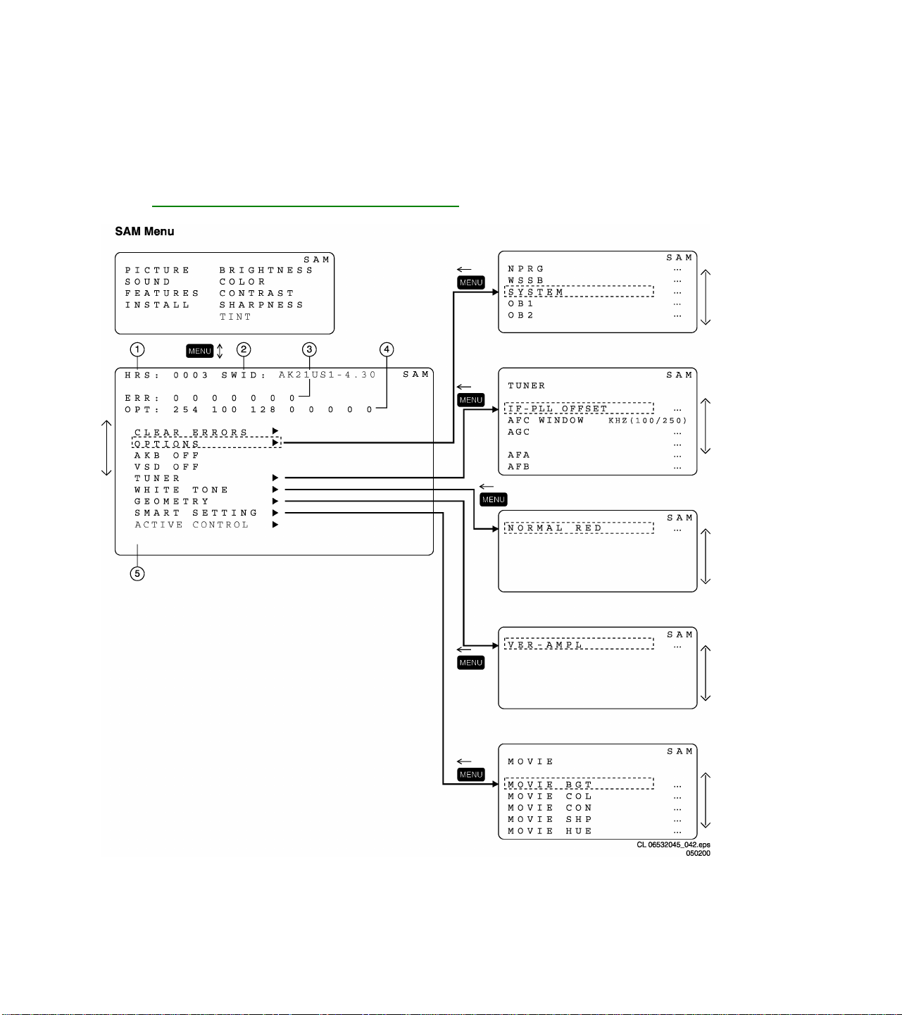
In the SAM the following information is displayed on the screen:

Service Alignment Mode screen and structure

Explanation notes/references:
1 Operation Hours (Run Timer):
This display indicates the accumulated total of operational hours. (Shown in hexadecimal
format)
2 Software identification of the main micro controller (AK21US1-4.30)
AK21 is the engineering chassis name for the Q8 chassis
• US1 is 2 letter and 1 digit combination to indicate the software type and the supported
languages:
• US = USA
• 1 = Main Software language version number
• 4.30 = sub-version number
3 Error buffer (7 errors possible) Displays the 7 most recent errors. The most recent
error is displayed at the upper left.
4 Option bytes (8 codes possible), summary of options are explained below.
5 Sub menus are listed in a scroll-menu.
SAM Menu Control
Menu items may be selected using the cursor UP/DOWN key.
• The selected item will be highlighted.
• When not all menu items will fit on the screen, pressing the cursor UP/DOWN key on the remote transmitter
will display the next/previous menu items.
With the cursor LEFT/RIGHT keys, it is possible to:
• (de)activate the selected menu item (e.g. GEOMETRY)
• change the value of the selected menu item ( e.g. VER-SLOPE )
• activate the selected submenu (e.g. SERV-BLK)
Access to normal user menu
Pressing the “MENU” button on the remote control switches between the SDM and the normal user menus
(with the SAM mode still active in the background). Pressing the “MENU” key in a submenu will return the
screen to the previous menu.
Software Alignment (Service Alignment Mode: SAM)
With the software alignments of the Service Alignment Mode, the geometry, white tone and tuner (IF) can be
aligned.
Tuner Options
Enter the Service Alignment Mode (SAM) by pressing the following key sequence on the remote control
transmitter: 0-6-2-5-9-6-INDEX
Do not allow the display to time out between entries while keying the sequence
It is also possible to enter the Service Alignment Mode by pressing the “VOLUME +” and “VOLUME -” key on
the local keyboard simultaneously for at least 4 seconds when the set is in SDM.

The option menu below shows the default values as set by the PEMG for US clusters:
Item 2US1 Remarks
IF-PLL OFFSET
AGC
AFA
AFB
AKB
VSD
P
P
P
P
P
P
Range 0->127 (Typically 31)
Range 0->63 (Typically 17)
0 or 1 (Read Only)
0 or 1 (Read Only)
ON
Vertical Setup (OFF) Except to display vertical line
White Tone Adjustment
Enter SAM (see Software alignments (Service Alignment Mode)). Press the Cursor Down button to highlight the
WHITE TONE menu item. Press the Cursor Right button to enter the WHITE TONE submenu. In the white tone
submenu the values for the color temperature values can be adjusted.
The color can be selected with the Cursor Up/Down buttons. The value can be changed with the Cursor
Left/Right buttons.
First the values for the NORMAL color temperature should be selected. Then the offset values for the DELTA
COOL and DELTA WARM mode can be selected. Note that the alignment values are non-linear
0 represents the middle value (no offset difference).

SAM REGISTER NAME DEFAULT VALUE
GEOMETRY VER. AMPL 12
VER. SLOPE 33
SERV BLANK OFF
HOR SHIFT 29
HOR. BOW 30
HOR. PARALLEL 31
EW. WIDTH 42
EW. PARA 24
EW. TRAP 21
EW. UCORN 10
EW. LCORN 33
H60 WIDTH 8
H60 SHIFT 6
V60 AMPL 5
VER SCOR 13
H60 PARA 2
VER. SHIFT 36
VER ZOOM 26
VER SCROLL 33
PICTURE BRIGHTNESS 31
PICTURE 31
COLOR 31
TINT 31
SHARPNESS 31
SUB-BRIGHT 31
WHITE TONE NORMAL RED 32
NORMAL GREEN 30
NORMAL BLUE 29
DELTA COOL RED 0
DELTA COOL GREEN 2
DELTA COOL BLUE 9
DELTA WARM RED 0
DELTA WARM GREEN -6
DELTA WARM BLUE -18
CATHODE DR 9

Geometry Adjustment
The geometry alignments menu contains 13 items for correct picture geometry alignment. In widescreen
models, the GEOMETRY SW is available for separate alignments of the super-wide (panorama) mode. The
geometry alignments are:
Initial set-up:
• Press the PICTURE button on the remote control repeatedly to change the Smart Picture setting to
"SPORTS."
• Enter SAM (see Software alignments (Service Alignment Mode)).
• Press the Menu Down button to select the GEOMETRY menu item.
• Press the Cursor Right button to enter the GEOMETRY submenu.
• Press the Cursor Down button to highlight the VER-SCOR submenu item.
• Use the Cursor Right buttons to adjust VER-SCOR to 13 for 27”, 28”, 32” and 34” picture tubes.
• Use the Cursor Right buttons to adjust VER-SCOR to 23 for 29” RF- sets
• Vertical zoom should be set at a default value of 35.
• Vertical scroll should be set at a default value of 32.
VER-SCOR aligns the vertical linearity, so that the vertical intervals of the grid-patterns are the same over the
entire height of the screen.
Extra Alignment
• Set Service blanking on SERV-BLK ON
• Adjust Vertical slope VER-SLOPE xx
• Set Service blanking OFF SERV-BLK OFF
General Alignment
• Adjust Vertical amplitude VER-AMPL xx
• Adjust Vertical shift VER-SHIFT xx
• Adjust Horizontal shift HOR-SHIFT xx
• Adjust Vertical height VER-ZOOM xx
• Adjust Vertical position VER-SCROLL xx
• Adjust Vertical linearity VER-SCOR xx
• Not used H60-SHIFT xx
• Not used V60-AMPL xx
• Adjust Horizontal width EW-WIDTH xx
• Adjust Parabola EW-PARA xx
• Adjust Up corner EW-UCORN xx
• Adjust low corner EW-LCORN xx
• Adjust Trapezium EW-TRAP xx
• Adjust Horizontal parallelogram HOR-PARALLEL xx
• Adjust Horizontal bow HOR-BOW xx

Geometry Submenu Item Descriptions
SERV-BLK: - To turn on/off the blanking of the lower half of the screen (To be used in combination with the
vertical slope alignment)
VER-SLOPE - To adjust the picture so the proportions are the same at the top and bottom of the screen.
(This alignment must be performed first, before all other vertical alignments)
VER-AMPL - To align the picture height (other vertical alignments are NOT compensated)
VERSHIFT - To align the vertical center of the picture to the vertical center of the CRT
HORSHIFT - To align the horizontal center of the picture to the horizontal center of the CRT
VER-ZOOM - To adjust picture height
VER-SCROLL - To vertically align the raster
VER-SCOR - To adjust the vertical linearity of the picture
H60-SHIFT - Not used
V60-AMPL - Not used
EW-WIDTH - To align the picture width (*)
EW PARA - To align straight vertical lines at the sides of the screen (*)
EW-UCORN - To align straight vertical lines in the upper corners of the screen (*)
EW-LCORN - To align straight vertical lines in the lower corners of the screen (*)
EW TRAP - To align straight vertical lines at the middle of the screen (*)
HOR-PARALLEL - To align straight vertical lines at the top and at the bottom of the screen; vertical rotation
around the center (*)
HOR-BOW - To align straight horizontal lines at the top and the bottom of the screen; horizontal rotation
around the center
Alignments indicated with (*) are not applicable for sets without East/West circuitry
Smart Settings
Enter the Service Alignment Mode (SAM) by pressing the following key sequence on the remote control
transmitter: 0-6-2-5-9-6-INDEX
Do not allow the display to time out between entries while keying the sequence
It is also possible to enter the Service Alignment Mode by pressing the “VOLUME +” and “VOLUME -” key on
the local keyboard simultaneously for at least 4 seconds when the set is in SDM.

Item
MOVIE BGT P Movie Brightness 0-99 34
MOVIE COL P Movie Color 0-99 34
MOVIE PIC P Movie Picture 0-99 75
MOVIE SHP P Movie Sharpness 0-99 50
MOVIE HUE P Movie Hue 0-99 50
SPORT BGT P Sport Brightness 0-99 34
SPORT COL P Sport Color 0-99 34
SPORT PIC P Sport Picture 0-99 67
SPORT SHP P Sport Sharpness 0-99 45
SPORT HUE P Sport Hue 0-99 50
WEAK BGT P Weak Brightness 0-99 34
WEAK COL P Weak Color 0-99 32
WEAK PIC P Weak Picture 0-99 59
WEAK SHP P Weak Sharpness 0-99 30
WEAK HUE P Weak Hue 0-99 50
MULTI BGT P Multimedia Brightness 0-99 34
MULTI COL P Multimedia Color 0-99 34
MULTI PIC P Multimedia Picture 0-99 71
MULTI SHP P Multimedia Sharpness 0-99 40
MULTI HUE P Multimedia Hue 0-99 50
2US1
Remarks
Typical
Settings
Active Control
Enter the Service Alignment Mode (SAM) by pressing the following key sequence on the remote control
transmitter: 0-6-2-5-9-6-INDEX
Do not allow the display to time out between entries while keying the sequence
It is also possible to enter the Service Alignment Mode by pressing the “VOLUME +” and “VOLUME -” key on
the local keyboard simultaneously for at least 4 seconds when the set is in SDM.

Item 2US1
VSG P MOVIE SHP 0-99 60
VSG P SPORT SHP 0-99 70
VSG P WEAK SHP 0-99 40
VSG P MULTI SHP 0-99 75
VSG P PSNL SHP 0-99 70
SG P MOVIE SHP 0-99 50
SG P SPORT SHP 0-99 50
SG P WEAK SHP 0-99 25
SG P MULTI SHP 0-99 70
SG P PSNL SHP 0-99 50
NM P MOVIE SHP 0-99 45
NM P SPORT SHP 0-99 35
NM P WEAK SHP 0-99 15
NM P MULTI SHP 0-99 55
NM P PSNL SHP 0-99 35
WK P MOVIE SHP 0-99 20
WK P SPORT SHP 0-99 20
WK P WEAK SHP 0-99 5
WK P MULTI SHP 0-99 40
WK P PSNL SHP 0-99 20
VWK P MOVIE SHP 0-99 0
VWK P SPORT SHP 0-99 2
VWK P WEAK SHP 0-99 0
VWK P MULTI SHP 0-99 4
VWK P PSNL SHP 0-99 0
Remarks
Typical
Settings
Options/Features
Options are used to control the presence / absence of certain features and hardware. There are two ways to
change the option settings, see Service Alignments Mode screens and structure.
Service Alignment Mode screen and structure

Changing a single option
An option may be selected with the MENU UP/DOWN keys and then changed with the MENU LEFT/RIGHT
keys.
Changing multiple options by changing option byte values
Option bytes make it possible to set all options quickly. An option byte, right hand column, represents the total
number of the option values within that group. All options of the Q8 can be controlled via the eight option bytes.
Select the option byte (OB1, OB2, OB3, OB4, OB5, OB6, OB7 or OB8) and enter the value
given under Option Bytes. This will automatically set all option byte values to the correct value.
List of options
Unless otherwise stated ON means the option is turned on or present, OFF means the option is turned off or not
present

Option Codes - NAFTA
Abbreviation Features Default values Option Byte
Value
SBNP Auto standby with no picture ON 128 1 OB1 = 251
C169 Picture setting for compress ON 64 1
E149 Picture setting for expand ON 32 1
SMCK Smart Clock ON 16 1
CBFL Comb filter ON 8 1
IPIX Incredible Picture OFF 4 0
IPMU Incredible Picture via menu ON 2 1
PLST Program List ON 1 1
SOSD Smart OSD ON 128 1 OB2 = 223
BLMU Blue Mute ON 64 1
VSLC Vertical slicing OFF 32 0
SURF Surf ON 16 1
CCAP Close Caption ON 8 1
DNRM Digital Noise Reduction in Menu
VMUT Video Mute ON 2 1
TIME TIMER ON 1 1
AAVL Automatic Volume Level ON 128 1 OB3 = 186
FUNN Fine Tuning OFF 64 0
SPKC Speaker Control ON 32 1
VCBK VChip Block un-rated ON 16 1
VBNR VChip Block No Rating ON 8 1
USRC US Backup Remote From MLink
BNUM Numbering for the Sliders ON 2 1
ROTI Picture Rotation OFF 1 0
SNIC ON=MSP3451OFF=3435/3415 OFF 128 0 OB4 = 62
TMWIN Time Window OFF 64 0
AOUT Audio OUT ON 32 1
INCF Selection color delay line ON 16 1
APC Auto Picture Control ON 8 1
NVM Non Volatile Memory ON 4 1
HIST Histogram ON 2 1
--- --- OFF 1 0
--- --- OFF 0 OB5 = 0
--- ---
--- ---
--- ---
ON 4 1
OFF 4 0
OFF
OFF
OFF
0 OB6 = 0
0 OB7 = 0
0 OB8 = 0
Bits Option
Bytes

Option Bytes
OPTION BYTE OB 1 OB 2 OB 3 OB 4 OB 5 OB 6 OB 7 OB 8
MODEL
29PD80 2225 251 223 250 56 0 0 0 0
29PD80 2235 251 223 186 56 0 0 0 0
32RF52 S327 254 184 126 236 208 0 0 0
32RF82 S327 254 190 253 217 224 0 0 0
36RF82 S327 254 190 253 217 224 0 0 0
Service Modes & Error Messages
The following topics are covered:
• Test points
• Service Modes and Dealer Service Tool (DST)
• Error code buffer and error codes
• The “blinking LED” procedure
• Trouble shooting tips
• Customer Service Mode
Test points
The Q8 chassis is equipped with test points shown on the CBA and the schematic diagrams.
Each test point has a reference number indicating the functional block in which it is located.
• A1-A2-A3, etc.: Test points for the audio processing circuitry [A6, C6]
• C1-C2-C3, etc.: Test points for the control circuitry [C8]
• F1-F2-F3, etc.: Test points for the frame drive and frame output circuitry [A3]
• I1-I2-I3, etc.: Test points for the Intermediate Frequency Circuitry [A4, C1]
• K1-K2-K3, etc: Test points for the Guide+ panel
• L1-L2-L3, etc.: Test points for the line drive and line output circuitry [A2] and PIP-panel
• P1-P2-P3, etc.: Test points for the power supply [A1]
• S1, S2, S3, etc.: Test points for the synchronization circuitry [C1]
• V1-V2-V3, etc.: Test points for the video processing circuitry [B, C2, C3]
Measurements should be performed under the following conditions:
Video: NTSC color bar signal
Audio: 3kHz left, 1kHz right
 Loading...